JP6373845B2 - Presence detector and method of operation of presence detector - Google Patents
Presence detector and method of operation of presence detector Download PDFInfo
- Publication number
- JP6373845B2 JP6373845B2 JP2015529173A JP2015529173A JP6373845B2 JP 6373845 B2 JP6373845 B2 JP 6373845B2 JP 2015529173 A JP2015529173 A JP 2015529173A JP 2015529173 A JP2015529173 A JP 2015529173A JP 6373845 B2 JP6373845 B2 JP 6373845B2
- Authority
- JP
- Japan
- Prior art keywords
- wave signal
- characteristic parameter
- presence detector
- detector
- time slot
- Prior art date
- Legal status (The legal status is an assumption and is not a legal conclusion. Google has not performed a legal analysis and makes no representation as to the accuracy of the status listed.)
- Expired - Fee Related
Links
Images


Classifications
-
- H—ELECTRICITY
- H05—ELECTRIC TECHNIQUES NOT OTHERWISE PROVIDED FOR
- H05B—ELECTRIC HEATING; ELECTRIC LIGHT SOURCES NOT OTHERWISE PROVIDED FOR; CIRCUIT ARRANGEMENTS FOR ELECTRIC LIGHT SOURCES, IN GENERAL
- H05B47/00—Circuit arrangements for operating light sources in general, i.e. where the type of light source is not relevant
- H05B47/10—Controlling the light source
- H05B47/105—Controlling the light source in response to determined parameters
- H05B47/115—Controlling the light source in response to determined parameters by determining the presence or movement of objects or living beings
-
- G—PHYSICS
- G01—MEASURING; TESTING
- G01S—RADIO DIRECTION-FINDING; RADIO NAVIGATION; DETERMINING DISTANCE OR VELOCITY BY USE OF RADIO WAVES; LOCATING OR PRESENCE-DETECTING BY USE OF THE REFLECTION OR RERADIATION OF RADIO WAVES; ANALOGOUS ARRANGEMENTS USING OTHER WAVES
- G01S15/00—Systems using the reflection or reradiation of acoustic waves, e.g. sonar systems
- G01S15/02—Systems using the reflection or reradiation of acoustic waves, e.g. sonar systems using reflection of acoustic waves
- G01S15/04—Systems determining presence of a target
-
- G—PHYSICS
- G08—SIGNALLING
- G08B—SIGNALLING OR CALLING SYSTEMS; ORDER TELEGRAPHS; ALARM SYSTEMS
- G08B13/00—Burglar, theft or intruder alarms
- G08B13/18—Actuation by interference with heat, light, or radiation of shorter wavelength; Actuation by intruding sources of heat, light, or radiation of shorter wavelength
- G08B13/181—Actuation by interference with heat, light, or radiation of shorter wavelength; Actuation by intruding sources of heat, light, or radiation of shorter wavelength using active radiation detection systems
- G08B13/187—Actuation by interference with heat, light, or radiation of shorter wavelength; Actuation by intruding sources of heat, light, or radiation of shorter wavelength using active radiation detection systems by interference of a radiation field
-
- H—ELECTRICITY
- H05—ELECTRIC TECHNIQUES NOT OTHERWISE PROVIDED FOR
- H05B—ELECTRIC HEATING; ELECTRIC LIGHT SOURCES NOT OTHERWISE PROVIDED FOR; CIRCUIT ARRANGEMENTS FOR ELECTRIC LIGHT SOURCES, IN GENERAL
- H05B47/00—Circuit arrangements for operating light sources in general, i.e. where the type of light source is not relevant
- H05B47/10—Controlling the light source
- H05B47/105—Controlling the light source in response to determined parameters
-
- Y—GENERAL TAGGING OF NEW TECHNOLOGICAL DEVELOPMENTS; GENERAL TAGGING OF CROSS-SECTIONAL TECHNOLOGIES SPANNING OVER SEVERAL SECTIONS OF THE IPC; TECHNICAL SUBJECTS COVERED BY FORMER USPC CROSS-REFERENCE ART COLLECTIONS [XRACs] AND DIGESTS
- Y02—TECHNOLOGIES OR APPLICATIONS FOR MITIGATION OR ADAPTATION AGAINST CLIMATE CHANGE
- Y02B—CLIMATE CHANGE MITIGATION TECHNOLOGIES RELATED TO BUILDINGS, e.g. HOUSING, HOUSE APPLIANCES OR RELATED END-USER APPLICATIONS
- Y02B20/00—Energy efficient lighting technologies, e.g. halogen lamps or gas discharge lamps
- Y02B20/40—Control techniques providing energy savings, e.g. smart controller or presence detection
Description
本発明は、概して、波信号を送信し、波信号のエコーに基づいて対象物の存在を検出するように構成された存在検出器の分野に関する。特に、本発明は、このような存在検出器間の通信に関する。 The present invention relates generally to the field of presence detectors configured to transmit a wave signal and detect the presence of an object based on an echo of the wave signal. In particular, the present invention relates to communication between such presence detectors.
超音波存在検出器は、超音波のバースト(又は連続)波を送出し、検出器で受信された環境からのエコーは、対象物(例えば人)がスペース(例えば部屋)に存在しているかどうかを決定するために使用される。ドップラーシフト測定法、飛行時間測定法、及び移動標的表示器(MTI)プロセッシングなどの種々異なる方法が、このような存在検出に使用され得る。存在検出器によって得られる存在情報は、1つ以上の照明デバイスを制御するための照明システムで使用され得る。 An ultrasonic presence detector emits a burst (or continuous) wave of ultrasonic waves, and echoes from the environment received by the detector indicate whether an object (eg a person) is present in a space (eg a room) Used to determine. Different methods such as Doppler shift measurement, time-of-flight measurement, and moving target indicator (MTI) processing can be used for such presence detection. The presence information obtained by the presence detector can be used in a lighting system for controlling one or more lighting devices.
大きなオープンスペース(例えばオープンオフィス)で存在検出器を使用する場合、複数の検出器がスペースをカバーするのに必要である。検出器間の干渉のリスクを軽減するために、時分割多重化技術が使用されてもよい。時分割多重技術を用いると、各検出器は固有のタイムスロットを持ち、該スロット内で検出器は存在検出を実行する。 When using presence detectors in large open spaces (eg, open offices), multiple detectors are needed to cover the space. To reduce the risk of interference between detectors, time division multiplexing techniques may be used. Using time division multiplexing techniques, each detector has a unique time slot within which the detector performs presence detection.
I2C、UART(Universal Asynchronous Receiver/Transmitter)、DALI(登録商標)(Digital Addressable Lighting Interface)、及びZigbee(登録商標)などの通信インフラ(又はプロトコル)が、照明システムの種々異なる部分間でデータを通信するための照明システムで使用されてもよい。
Communication infrastructures (or protocols) such as I2C, UART (Universal Asynchronous Receiver / Transmitter), DALI (registered trademark) (Digital Addressable Lighting Interface), and Zigbee (registered trademark) communicate data between different parts of the lighting system May be used in a lighting system.
本発明の目的は、存在情報を通信することができる存在検出器と、別の存在検出器から存在情報を受信することができる存在検出器とを提供することである。本発明の目的は、このような存在検出器の動作方法を提供することでもある。 An object of the present invention is to provide a presence detector capable of communicating presence information and a presence detector capable of receiving presence information from another presence detector. It is also an object of the present invention to provide a method for operating such a presence detector.
これら及び他の目的は、独立請求項に規定される存在検出器及び存在検出器の動作方法によって達成される。好ましい実施形態は、従属請求項に規定される。 These and other objects are achieved by a presence detector and a method of operating the presence detector as defined in the independent claims. Preferred embodiments are defined in the dependent claims.
本発明の第1態様によれば、存在検出器の動作方法が提供される。方法は、第1波信号のエコーに基づいて対象物の存在を検出するため第1波信号を第1タイムスロットにおいて送信するステップと、対象物の存在が検出された場合、第1波信号の特性パラメータを変更するステップとを有する。 According to a first aspect of the invention, a method of operating a presence detector is provided. The method includes transmitting a first wave signal in a first time slot to detect the presence of an object based on an echo of the first wave signal; and if the presence of the object is detected, Changing the characteristic parameter.
本発明の第2態様によれば、存在検出器の動作方法が提供される。方法は、別の存在検出器から送信される第1波信号の特性パラメータを第1タイムスロットにおいて監視するステップと、第1波信号の監視される特性パラメータの変更が検出されると、制御信号を送信するステップとを有する。 According to a second aspect of the invention, a method of operating a presence detector is provided. The method monitors a characteristic parameter of a first wave signal transmitted from another presence detector in a first time slot, and when a change in the monitored characteristic parameter of the first wave signal is detected, the control signal Transmitting.
本発明の第3態様によれば、存在検出器が提供される。存在検出器は、第1波信号のエコーに基づいて対象物の存在を検出するため第1波信号を第1タイムスロットにおいて送信し、対象物の存在が検出された場合、第1波信号の特性パラメータを変更するように構成された存在検出ユニットを有する。 According to a third aspect of the invention, a presence detector is provided. The presence detector transmits the first wave signal in the first time slot to detect the presence of the object based on the echo of the first wave signal, and when the presence of the object is detected, Having a presence detection unit configured to change the characteristic parameter;
本発明の第4態様によれば、存在検出器が提供される。存在検出器は、別の存在検出器から送信される第1波信号の特性パラメータを第1タイムスロットにおいて監視し、第1波信号の監視される特性パラメータの変更が検出されると、制御信号を送信するように構成された監視ユニットを有する。 According to a fourth aspect of the present invention, a presence detector is provided. The presence detector monitors the characteristic parameter of the first wave signal transmitted from another presence detector in the first time slot, and when the change of the monitored characteristic parameter of the first wave signal is detected, the control signal Has a monitoring unit configured to transmit.
単純化のために、本発明の第3態様による存在検出器は、本明細書において、以下、第1存在検出器と呼ばれ、本発明の第4態様による存在検出器は、第2存在検出器と呼ばれる。従って、本発明の第1態様による方法は、第1存在検出器の動作方法と呼ばれ、本発明の第2態様による方法は、第2存在検出器の動作方法と呼ばれる。しかしながら、「第1(first)」及び「第2(second)」なる用語は、決して限定するものとして見なされるべきではない。 For the sake of simplicity, the presence detector according to the third aspect of the present invention will hereinafter be referred to as the first presence detector, and the presence detector according to the fourth aspect of the present invention will be referred to as the second presence detection. Called a vessel. Accordingly, the method according to the first aspect of the present invention is referred to as a method of operating a first presence detector, and the method according to the second aspect of the present invention is referred to as a method of operating a second presence detector. However, the terms “first” and “second” should in no way be considered limiting.
特定の領域又はサブエリアの付近の領域又はサブエリアに設置された照明デバイスは、その特定のサブエリアにおける存在検出に応じて対処し得るため、スペースにおける隣接する領域又はサブエリア間の存在情報を通信することは、有用であり得る。例えば、そのサブエリアで存在が検出された場合、フルの照明レベルが、特定のサブエリアに提供されてもよく、全照明から暗闇(すなわち照明無し)への極端な移行を低減するために、半照明レベルが隣接するサブエリアに提供されてもよい。スペースにおける種々異なるサブエリア間の存在情報のこのような通信を得るためには、前述のように、I2C、UART、DALI、及びZigbee(登録商標)などの通信インフラを使用することができる。しかしながら、全てのこれら通信インフラは、有線接続のための銅線及び追加の電子機器などの付加的なハードウエアを必要とし、これは、材料費の高額な請求をもたらし、設置の複雑さ及びコストを増加させる。本発明者は、存在検出に使用される波信号これ自体を存在情報の通信に利用し、これによって、上記に述べたような追加の通信チャネルの必要性を削減できることに気が付いた。 Since lighting devices installed in an area or subarea near a specific area or subarea can deal with the presence detection in that specific subarea, the presence information between adjacent areas or subareas in the space can be Communicating can be useful. For example, if a presence is detected in that subarea, a full lighting level may be provided for that particular subarea, to reduce the extreme transition from full lighting to darkness (i.e. no lighting) Semi-illumination levels may be provided in adjacent subareas. In order to obtain such communication of presence information between different sub-areas in space, a communication infrastructure such as I2C, UART, DALI, and Zigbee® can be used as described above. However, all these communications infrastructures require additional hardware such as copper wires and additional electronics for wired connections, which results in high billing for material costs and the complexity and cost of installation. Increase. The inventor has realized that the wave signal itself used for presence detection can be utilized for presence information communication, thereby reducing the need for additional communication channels as described above.
本発明によれば、第1存在検出器は、(例えば第1存在検出器の検出エリア内で)存在が検出された場合、第1波信号の特性パラメータ(又は特徴)を変更することによって存在情報を通信する。好ましくは、存在が検出されない場合、第1波信号の特性パラメータは変更されないままである。従って、第1波信号の変更された特性パラメータは、第1存在検出器によって存在が検出されたことの表示である。第1波信号の特性パラメータの変更は、その後、変更について(第1検出器からの)第1波信号を監視する第2存在検出器によって検出されてもよく、検出されるとすぐに、第2存在検出器は制御信号を送信してもよい。このように、存在情報は、第1存在検出器から第2存在検出器に通信される。存在情報の通信は、存在が検出された(又はされている)サブエリアの付近に位置付けられるサブエリアにおいて、照明レベル、HVAC(暖房、換気、及び空調)パラメータ又は任意の他の所望のパラメータの調整などの取るべき更なるアクションを可能にする。第2存在検出器によって送信される制御信号は、好ましくは照明システム内の(第2存在検出器から第2存在検出器に関連する光源への電気信号などの)内部信号であってもよく、すなわち存在検出のための波信号でなくてもよい。 According to the present invention, the first presence detector is present by changing the characteristic parameter (or feature) of the first wave signal when presence is detected (eg within the detection area of the first presence detector). Communicate information. Preferably, if no presence is detected, the characteristic parameter of the first wave signal remains unchanged. Thus, the altered characteristic parameter of the first wave signal is an indication that the presence has been detected by the first presence detector. The change in the characteristic parameter of the first wave signal may then be detected by a second presence detector that monitors the first wave signal (from the first detector) for change, and once detected, The two presence detector may send a control signal. In this way, presence information is communicated from the first presence detector to the second presence detector. Presence information communication is performed for lighting levels, HVAC (heating, ventilation, and air conditioning) parameters or any other desired parameters in a sub-area located near the sub-area in which presence is detected (or is). Allows further actions to be taken, such as adjustments. The control signal transmitted by the second presence detector may preferably be an internal signal (such as an electrical signal from the second presence detector to the light source associated with the second presence detector) in the illumination system; That is, it may not be a wave signal for presence detection.
存在検出ユニット(又はプロセッシングユニット)は、波信号の送信及び特性パラメータの変更をそれぞれ行うための単一の構成要素(若しくはユニット)、又は代替的に別体の構成要素(若しくはユニット)を有してもよい。更に、監視ユニットは、波信号の特性パラメータの監視及び制御信号の送信をそれぞれ行うための単一の構成要素(若しくはユニット)、又は代替的に別体の構成要素(若しくはユニット)を有してもよいことに留意されたい。 The presence detection unit (or processing unit) has a single component (or unit) for transmitting wave signals and changing characteristic parameters, respectively, or alternatively a separate component (or unit). May be. Further, the monitoring unit has a single component (or unit) for monitoring the characteristic parameters of the wave signal and transmitting the control signal, respectively, or alternatively a separate component (or unit). Note that it is also possible.
本発明は、付加的な通信システムを使用せずに存在情報が種々異なる存在検出器間で通信でき、これによって技術的な複雑さ及びコストを削減され得る点で有利である。更に、存在情報は、存在検出器自体の間で直接通信され得るため、存在情報を集め、転送するための中央ユニットは不要である。 The present invention is advantageous in that presence information can be communicated between different presence detectors without using an additional communication system, thereby reducing technical complexity and cost. Furthermore, since the presence information can be communicated directly between the presence detectors themselves, a central unit for collecting and transferring presence information is not necessary.
波信号の特性パラメータの変更の検出は、例えば特性パラメータの増加若しくは減少を検出することによって、又は特性パラメータが所定の基準値を超える若しくは下回ることによって実現されてもよい。 Detection of a change in the characteristic parameter of the wave signal may be realized, for example, by detecting an increase or decrease in the characteristic parameter, or when the characteristic parameter exceeds or falls below a predetermined reference value.
下記に説明される本発明の実施形態は、互いに、並びに、本発明の第1、第2、第3及び第4態様のいずれか一つと組み合わされてもよい。 The embodiments of the present invention described below may be combined with each other and with any one of the first, second, third and fourth aspects of the present invention.
実施形態によれば、第1波信号(及び、任意選択で、更に第2存在検出器によって送信される任意の波信号)は、超音波信号又はレーダ信号であってもよい。超音波又はレーダ技術は共に、波(超音波又はレーダ波)を送信し、環境からの送信された波のエコーを測定することによって存在検出を行うというコンセプトに基づく。 According to embodiments, the first wave signal (and optionally any wave signal further transmitted by the second presence detector) may be an ultrasound signal or a radar signal. Both ultrasound or radar technologies are based on the concept of detecting presence by transmitting waves (ultrasound or radar waves) and measuring the echoes of the transmitted waves from the environment.
本発明の実施形態によれば、第1波信号の特性パラメータを変更するステップは、第1波信号の第1特性パラメータを第2特性パラメータに変更するステップを有してもよく、第1波信号は、変更後、第2特性パラメータで送信されてもよい。従って、第1存在検出器は、存在が検出されるまで第1特性パラメータ(又は値)を有する第1波信号を送信し、検出されると、第1存在検出器は、第1波信号を、代わりに第2特性パラメータで送信し始めるように構成されてもよい。本実施形態は、第1存在検出器は、存在が検出されたことを通信するのに、第1特性パラメータを第2特性パラメータに切り替えるだけであるという点で有利である。 According to the embodiment of the present invention, the step of changing the characteristic parameter of the first wave signal may include the step of changing the first characteristic parameter of the first wave signal to the second characteristic parameter. The signal may be transmitted with the second characteristic parameter after being changed. Accordingly, the first presence detector transmits a first wave signal having a first characteristic parameter (or value) until presence is detected, and when detected, the first presence detector detects the first wave signal. Alternatively, it may be configured to start transmitting with the second characteristic parameter. This embodiment is advantageous in that the first presence detector only switches from the first characteristic parameter to the second characteristic parameter to communicate that presence has been detected.
更に、第2存在検出器を動作する方法は、第1波信号の第2(又は所定の)特性パラメータを検出し、好ましくは第2特性パラメータを検出すると、制御信号を送信するステップを有してもよい。制御信号は、取るべき更なるアクションを可能にし、例えば制御信号は、第2存在検出器に関連するサブエリアの照明を作動させる(又は温度を上げる)ことを可能にする。第1特性パラメータは、第2存在検出器によって検出される必要はない。つまり、第2特性パラメータの検出は、第1検出器が存在を検出したかどうかを決定するのに十分である。 Further, the method of operating the second presence detector comprises detecting a second (or predetermined) characteristic parameter of the first wave signal, preferably transmitting a control signal upon detecting the second characteristic parameter. May be. The control signal allows further action to be taken, for example the control signal allows to activate (or increase the temperature) the illumination of the sub-area associated with the second presence detector. The first characteristic parameter need not be detected by the second presence detector. That is, detection of the second characteristic parameter is sufficient to determine whether the first detector has detected presence.
本発明の実施形態によれば、第1波信号を第2特性パラメータで送信することは、第1タイムスロットの通信サブスロットにおいて行われてもよい。第1タイムスロットは、存在検出を行うための第1存在検出器専用のタイムスロットであってもよい。隣接する検出器は、好ましくは存在検出器によって送信される波信号間の干渉を低減させるために、第1タイムスロットからオフセットされた他のタイムスロットにおいて存在検出を行ってもよい。本実施形態によれば、第1タイムスロットは、通信サブスロットを有してもよく、第1タイムスロットの一部は、存在情報の通信の専用である。任意選択で、第1存在検出器は、第1波信号を第2特性パラメータで送信した後、第1波信号を第1特性パラメータで送信するように戻る。 According to the embodiment of the present invention, transmitting the first wave signal with the second characteristic parameter may be performed in a communication subslot of the first time slot. The first time slot may be a time slot dedicated to the first presence detector for performing presence detection. Adjacent detectors may perform presence detection in other time slots that are offset from the first time slot, preferably to reduce interference between wave signals transmitted by the presence detector. According to this embodiment, the first time slot may have a communication sub-slot, and a part of the first time slot is dedicated to communication of presence information. Optionally, the first presence detector returns to transmit the first wave signal with the first characteristic parameter after transmitting the first wave signal with the second characteristic parameter.
更に、第2存在検出器を動作する方法は、第1波信号の特性パラメータを少なくとも通信サブスロットにおいて監視するステップを有してもよい。第2存在検出器は、第1タイムスロットの残りの時間において監視を行う必要はない。 Further, the method of operating the second presence detector may comprise monitoring the characteristic parameter of the first wave signal at least in the communication subslot. The second presence detector need not monitor for the remaining time of the first time slot.
更に、第1波信号のエコーに基づいて存在を検出するための第1波信号を第1特性パラメータで送信することは、通信サブスロットからオフセットされ、通信サブスロットより前の第1タイムスロットの存在検出サブスロットにおいて行われてもよい。従って、第1タイムスロットでは、対象物が存在しているかどうかの決定が最初に(存在検出サブスロットにおいて)行われ、その後、存在検出サブスロットにおいて存在が検出されている(検出された)場合、存在情報は、(通信サブスロットにおいて)第1波信号を第2特性パラメータで送信することによって通信される。存在検出サブスロットにおいて存在が検出されない場合、通信サブスロットにおいて通信もアクションも行われなくてもよい、又は代替的に、第1存在検出器は、この場合は、通信サブスロットにおいて、第1波信号を第1特性パラメータで送信し続けてもよい。「通信サブスロット(communication sub-slot)」なる用語が使用されているが、通信は、各通信サブスロットにおいて行われる必要はなく、存在が検出されている場合にのみ行われてもよいことに留意されたい。 Furthermore, transmitting the first wave signal for detecting the presence based on the echo of the first wave signal with the first characteristic parameter is offset from the communication subslot and is transmitted in the first time slot before the communication subslot. It may be performed in the presence detection subslot. Thus, in the first time slot, the determination of whether an object is present is made first (in the presence detection subslot) and then presence is detected (detected) in the presence detection subslot. The presence information is communicated by transmitting the first wave signal with the second characteristic parameter (in the communication subslot). If no presence is detected in the presence detection subslot, no communication or action may be performed in the communication subslot, or alternatively, the first presence detector in this case is the first wave in the communication subslot. The signal may continue to be transmitted with the first characteristic parameter. Although the term “communication sub-slot” is used, communication need not occur in each communication sub-slot and may only occur if presence is detected. Please keep in mind.
代替的に、又は補完として、本発明の実施形態によれば、第1タイムスロットは、繰り返されてもよく、第1波信号を第2特性パラメータで送信することは、繰り返される第1タイムスロットにおいて行われてもよい。本実施形態によれば、通信は、繰り返される(後続の)第1タイムスロットにおいて代わりに(又は補完として)行われるため、第1タイムスロットは、サブスロットに分割される必要はない。第1タイムスロットは、時分割二重通信システムにおけるように、複数のタイムスロットを有するタイムフレームの一部であってもよい。第1存在検出器は、第2特性パラメータの第1波信号によって、又は更に別の繰り返される第1タイムスロットにおいて第1特性パラメータの第1波信号を送信するように戻ることによって、存在検出(又は存在の監視)を行い続ける。 Alternatively or as a supplement, according to an embodiment of the invention, the first time slot may be repeated, and transmitting the first wave signal with the second characteristic parameter is repeated in the first time slot. May be performed. According to this embodiment, the first time slot does not have to be divided into subslots, since communication takes place instead (or as a complement) in repeated (subsequent) first time slots. The first time slot may be a part of a time frame having a plurality of time slots, as in a time division duplex communication system. The first presence detector may detect presence by returning a first wave signal of the first characteristic parameter by a first wave signal of the second characteristic parameter, or in yet another repeated first time slot. (Or presence monitoring).
本発明の実施形態によれば、第1存在検出器を動作する方法は、更に、第1タイムスロットからオフセットされた第2タイムスロットにおいて、別の(例えば隣接する)存在検出器から送信される第2波信号の特性パラメータを監視するステップと、第2波信号の監視される特性パラメータの変更を検出すると、又は監視される特性パラメータの特定の(好ましくは所定の)値を検出すると制御信号を送信するステップとを有してもよい。よって、第1存在検出器は、これ自体によって生成された存在情報を通信することに加えて、他の存在検出器からの存在情報も受信又は検出するように構成されてもよい。監視するステップは、第1存在検出器の監視ユニットによって行われてもよく、これは、存在検出器と同じ部分に又は別体の部分として含まれてもよい。 According to an embodiment of the present invention, the method of operating a first presence detector is further transmitted from another (eg, adjacent) presence detector in a second time slot offset from the first time slot. Monitoring the characteristic parameter of the second wave signal and detecting a change in the monitored characteristic parameter of the second wave signal or detecting a specific (preferably predetermined) value of the monitored characteristic parameter May be included. Thus, the first presence detector may be configured to receive or detect presence information from other presence detectors in addition to communicating presence information generated by itself. The step of monitoring may be performed by the monitoring unit of the first presence detector, which may be included in the same part as the presence detector or as a separate part.
実施形態によれば、(第1存在検出器によって送信される)制御信号は、第2波信号の変更された特性パラメータ(の代表など)に基づいてもよい。同様に、第2存在検出器によって送信される制御信号は、第1波信号の変更された特性パラメータに基づいてもよい。本実施形態によれば、新しい特性パラメータに基づいてアクションを取り得る。例えば、(存在検出器が配置されたスペースの少なくともいくつかのサブエリアにおける環境に影響を与える)種々異なるアクションが、種々異なる特性パラメータ(又は値)の結果として取り得る。 According to embodiments, the control signal (transmitted by the first presence detector) may be based on a modified characteristic parameter (such as a representative) of the second wave signal. Similarly, the control signal transmitted by the second presence detector may be based on the modified characteristic parameter of the first wave signal. According to this embodiment, an action can be taken based on a new characteristic parameter. For example, different actions (which affect the environment in at least some sub-areas of the space where the presence detector is located) can be taken as a result of different characteristic parameters (or values).
実施形態によれば、第1タイムスロットは(任意選択で第2タイムスロットも)、周期的に又はタイムスケジュールに従って繰り返されてもよく、存在検出、及び任意選択で、存在が検出された場合は存在情報の通信も、繰り返しの態様において行われてもよい。例えば、第1タイムスロットは、及び好ましくは、第2タイムスロットも、繰り返されるタイムフレームにおいて提供されてもよい。タイムフレームは、存在検出器システムの各存在検出器又は少なくとも隣接する存在検出器のグループの各存在検出器に対して、タイムスロットを有してもよい。各存在検出器は、その後、存在検出を行うための各繰り返されるタイムフレームにおいて専用のタイムスロットを有し、存在検出器によって送信される信号間の干渉は低減される。好ましくは、第1タイムスロットは、第2タイムスロットとオーバーラップしない。 According to an embodiment, the first time slot (and optionally the second time slot) may be repeated periodically or according to a time schedule, and if presence is detected and optionally presence is detected. Communication of presence information may also be performed in a repetitive manner. For example, a first time slot, and preferably a second time slot may also be provided in a repeated time frame. The time frame may have a time slot for each presence detector in the presence detector system or at least each presence detector in a group of adjacent presence detectors. Each presence detector then has a dedicated time slot in each repeated time frame for performing presence detection, and interference between signals transmitted by the presence detector is reduced. Preferably, the first time slot does not overlap with the second time slot.
本発明の実施形態によれば、第1波信号の特性パラメータは(及び第2波信号の特性パラメータも)、第1波信号の周波数、パルス長、パルスの数、及び振幅の少なくとも1つであってもよい。波信号は、存在情報を伝達するために任意の適切なやり方で変更(変調)されてもよい。(存在検出器によって検出された)存在は、例えば波信号の、周波数、パルス長、(例えば1バースト内の)パルスの数、及び/又は振幅を1つの値から別の値へとシフトすることによって通信されてもよい。存在が検出された場合に(例えば周波数及び/又は振幅に関して)特定のパターンに従って波信号を変調するなど、より複雑な技術も予想される。 According to the embodiment of the present invention, the characteristic parameter of the first wave signal (and the characteristic parameter of the second wave signal) is at least one of the frequency, the pulse length, the number of pulses , and the amplitude of the first wave signal. There may be. The wave signal may be modified (modulated) in any suitable manner to convey presence information. Presence (detected by a presence detector) shifts the frequency, pulse length, number of pulses (eg, in one burst) and / or amplitude of a wave signal from one value to another May be communicated by. More complex techniques are also envisaged, such as modulating the wave signal according to a specific pattern (eg in terms of frequency and / or amplitude) when presence is detected.
本発明の実施形態によれば、方法は、更に、検出された対象物によって行われるアクティビティのタイプを決定するステップと、決定されたアクティビティのタイプに基づいて、所定の特性パラメータのセットから特性パラメータ(特性値など)を選択するステップと、第1波信号の特性パラメータを選択された特性パラメータに変更するステップとを有してもよい。アクティビティのタイプは、第1波信号のエコーに基づいて決定されてもよい。超音波ベースの存在検出器は、対象物の単なる存在を決定するだけでなく、どのくらいの動き及びどのくらいの距離で動きが検出されたか(複数の存在検出器の場合は、どの角度で動きが検出されたか)など更なる存在情報も決定してもよい。このような存在情報は、アクティビティのタイプを決定するのに使用されてもよい。例えば、存在検出器の下で検出された小さな動きは、人が自分のデスクで仕事をしていると解釈され、時間にわたって複数の位置で及びやや長い距離で検出された大きな動きは、人が歩いているとして解釈される。 According to an embodiment of the present invention, the method further comprises determining a type of activity performed by the detected object and, based on the determined type of activity, the characteristic parameter from the predetermined set of characteristic parameters. You may have the step which selects (characteristic value etc.), and the step which changes the characteristic parameter of a 1st wave signal into the selected characteristic parameter. The type of activity may be determined based on the echo of the first wave signal. Ultrasound-based presence detectors not only determine the mere presence of an object, but also how much movement and how far the movement was detected (in the case of multiple presence detectors, at which angle the movement is detected) Further presence information may also be determined. Such presence information may be used to determine the type of activity. For example, a small movement detected under a presence detector is interpreted as a person working at his desk, and a large movement detected at multiple locations and at slightly longer distances over time Interpreted as walking.
本実施形態は、存在検出器間で通信される存在情報は、検出された対象物によって行われるアクティビティの表示を有し、アクティビティに基づいて(照明レベルの調整などの)アクションを取り得るという点で有利である。 In this embodiment, presence information communicated between presence detectors has an indication of activity performed by the detected object, and can take action (such as adjusting lighting levels) based on the activity. Is advantageous.
本発明の実施形態では、第1及び第2存在検出器は、等しく構成されてもよい(すなわち同じ原理に従って動作する)点に留意されたい。従って、第1存在検出器について上記に説明された任意の実施形態は、同じく第2存在検出器に適用されてもよく、第2存在検出器について上記に説明された任意の実施形態は、同じく第1存在検出器に適用されてもよい。例えば、第2存在検出器の動作方法は、更に、第1タイムスロットからオフセットされた第2タイムスロットにおいて、第2波信号のエコーに基づいて対象物の存在を検出するための第2波信号を送信するステップと、対象物の存在が検出された場合、第2波信号の特性パラメータを変更するステップとを有してもよい。 Note that in embodiments of the present invention, the first and second presence detectors may be equally configured (ie, operate according to the same principles). Thus, any embodiment described above for the first presence detector may also be applied to the second presence detector, and any embodiment described above for the second presence detector may also be It may be applied to the first presence detector. For example, the operation method of the second presence detector further includes a second wave signal for detecting the presence of an object based on an echo of the second wave signal in a second time slot offset from the first time slot. And the step of changing the characteristic parameter of the second wave signal when the presence of the object is detected.
本発明の実施形態によれば、存在検出器システムが提供される。存在検出器システムは、本発明の第3実施形態による第1存在検出器と、本発明の第4実施形態による第2存在検出器とを有してもよい。本実施形態は、少なくとも第1存在検出器から第2存在検出器へ存在情報を通信することができる少なくとも2つの存在検出器を備える存在検出器システムを提供する。 According to an embodiment of the present invention, a presence detector system is provided. The presence detector system may include a first presence detector according to the third embodiment of the present invention and a second presence detector according to the fourth embodiment of the present invention. The present embodiment provides a presence detector system comprising at least two presence detectors capable of communicating presence information from at least a first presence detector to a second presence detector.
本発明の実施形態によれば、照明システムが提供され、これは、照明デバイスと、本発明の第4実施形態による存在検出器(本明細書では第2検出器と呼ばれる)とを有してもよい。照明デバイスは、(第2)存在検出器によって送信された制御信号に基づいて制御される(動作する)ように構成されてもよい。本実施形態によれば、照明デバイスは、別の(例えば隣接する)存在検出器から受信した存在情報に基づいて制御されてもよい。例えば、存在が隣接する存在検出器で検出された場合、照明デバイスの照明レベルは、半照明レベルに調整(例えばスイッチが入る)されてもよい。 According to an embodiment of the present invention, an illumination system is provided, which comprises an illumination device and a presence detector (referred to herein as a second detector) according to a fourth embodiment of the present invention. Also good. The lighting device may be configured to be controlled (operated) based on a control signal transmitted by the (second) presence detector. According to this embodiment, the lighting device may be controlled based on presence information received from another (eg, adjacent) presence detector. For example, if presence is detected by an adjacent presence detector, the illumination level of the lighting device may be adjusted (eg, switched on) to a half-illumination level.
本発明は、請求項に記載された特徴の全ての可能な組み合わせに関する点に留意されたい。本発明の特徴の更なる目的、及び本発明による有利な点は、下記の詳細な開示内容、図面及び添付の請求項の精査をすれば明らかになるだろう。当業者は、本発明の種々異なる特徴は、以下に説明された実施形態以外の実施形態を作るために組み合わせることができることを理解する。 It should be noted that the invention relates to all possible combinations of the features recited in the claims. Further objects of the features of the present invention and advantages of the present invention will become apparent from a review of the following detailed disclosure, drawings, and appended claims. Those skilled in the art will appreciate that the different features of the present invention can be combined to create embodiments other than those described below.
本発明のこれら及び他の態様は、ここで、発明の実施形態を示す添付の図面を参照して、より詳細に説明されるだろう。 These and other aspects of the invention will now be described in more detail with reference to the accompanying drawings, which illustrate embodiments of the invention.
全ての図面は模式的であり、縮小拡大する必要はなく、概して発明を解明するために必要な部分を示すのみであり、他の部分は、省略されてもよく又は単に提案されてもよい。 All drawings are schematic and do not need to be scaled up and generally show only the parts necessary to elucidate the invention, and other parts may be omitted or simply proposed.
本発明の実施形態による照明システムは、以下に図1a及び図1bを参照して説明される。 An illumination system according to an embodiment of the present invention is described below with reference to FIGS. 1a and 1b.
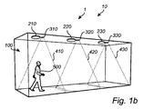
照明システム1は、第1照明デバイス210、第2照明デバイス220、及び第3照明デバイス230を有する。照明システム1は、更に、第1照明デバイス210に接続される第1存在検出器310、第2照明デバイス220に接続される第2存在検出器320、及び第3照明デバイス230に接続される第3存在検出器330を有する存在検出器システム10を有する。
The lighting system 1 includes a
各存在検出器310、320、330は、存在検出を行い、存在が検出されたかどうかを示す存在情報を他の存在検出器310、320、330に通信する(送信する)ように構成された存在検出ユニット311、321、331を有する。対象物500の存在に対して、第1存在検出器310の存在検出ユニット311は、スペース100の第1サブエリア410を監視し、第2存在検出器320の存在検出ユニット321は、スペース100の第2サブエリア420を監視し、第3存在検出器330の存在検出ユニット331は、スペース100の第3サブエリア430を監視するように構成される。各存在検出器310、320、330が監視するサブエリア410、420、430は、好ましくは関連する照明デバイス210、220、230が照明するエリアと一致する。存在(又は存在検出)の監視は、(超音波又はレーダ信号などの)波信号を送出し、環境から受信した波信号のエコーを測定することによって行われ、測定されたエコーに基づいて存在を決定する。存在検出ユニット311、321、331は、それぞれ波信号を送信し、波信号からのエコーを受信するためのトランシーバを有する。
Each
各存在検出器310、320、330は、更に、他の存在検出器310、320、330によって通信される存在情報を監視する(及び受信する)ための監視ユニット312、322、332を有する。監視ユニット312、322、332は、存在検出ユニット311、321、331と共に主要存在検出器部分の中に含まれてもよく、又は主要存在検出器部分に接続される別部分として含まれてもよい。第1存在検出器310の監視ユニット312は、第1存在検出器310の存在検出ユニット311によって得られる存在情報と、他の存在検出器320、330によって通信される存在情報とに基づいて、第1照明デバイス210に制御信号を送信するように構成される。第2及び第3存在検出器320、330の監視ユニット322、332も同様に構成される。
Each
存在検出器310、320、330によって送信される波信号間の干渉を減少させるために、時分割多重技術が好ましくは利用されてもよく、これは、ここで、特に図2を参照して説明される。タイムフレーム800は、タイムスロット810、820、830に分割され、例えば存在検出器の数とタイムスロットの数とは同じ数である。しかしながら、存在検出器が互いの測定に影響を与えないことを保証する互いに十分に遠く離れて設置された複数の存在検出器に対して、全く同一のタイムスロットが使用されてもよい。
In order to reduce interference between the wave signals transmitted by the
存在検出の実行に対して、第1タイムスロット810は、第1存在検出器310の専用であり、第2タイムスロット820は、第2存在検出器320の専用であり、第3タイムスロット830は、第3存在検出器330の専用である。タイムフレーム800は、存在検出が行われるべきである限り繰り返されてもよい。
For performing presence detection, the
実施形態によれば、各タイムスロット810、820、830は、それぞれ存在検出サブスロット811、821、831に分割されてもよく、それぞれ後続の通信サブスロット812、822、832に分割されてもよい。存在検出サブスロット811、821、831では、存在検出器310、320、330は、存在検出を行い(存在に対してそのサブエリアを監視する)、通信サブスロット812、822、832では、存在検出器310、320、330は、存在が検出された場合に通信する。代替的に、例えば専用タイムスロットが存在検出サブスロットと通信サブスロットとに分割されていない場合、各存在検出器310、320、330は、(繰り返されるタイムフレームにおいて)その後続のタイムスロットを、存在情報を通信するために利用する。存在検出器は、その後、後続のタイムスロットにおいて存在に対して監視を続けるが、変更した特性パラメータを用い、これによって他の存在検出器に存在情報を通信する。
According to the embodiment, each
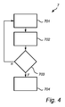
存在の監視(存在検出の実行)及び存在検出器310と320と330との間の存在情報の通信は、下記により詳細に説明される。図3及び図4は、存在検出器310、320、330の動作方法の模式的な図を示す。当然のことながら、方法が、下記に第1存在検出器310に関して説明されているが、該方法は、第2及び第3存在検出器320、330のうちのいずれか一つに同等に適用されてもよく、違いは、第2存在検出器320は、存在検出及び存在情報の通信を第2タイムスロット820で行い、第3存在検出器330は、存在検出及び存在情報の通信を第3タイムスロット830で行う点である。
Presence monitoring (perform presence detection) and communication of presence information between
まず、存在検出器の存在検出ユニットの動作方法6が図3を参照して説明される。第1存在検出器310の存在検出ユニット311は、ステップ601で、第1波信号に対して第1特性パラメータ、これは本例では周波数A(例えば40kHz)を設定し、ステップ602で第1タイムスロット810を待つ。第1タイムスロット810が来ると、存在検出ユニット311は、第1特性パラメータ、すなわち周波数Aで第1波信号をサブエリア410に向かって送信する。第1波信号は、環境(すなわち、サブエリア410に存在する壁、床、場合により人などの移動対象物)によって反射され、反射された第1波信号の一部は、その後、存在検出ユニット311で(エコーとして)受信される。ステップ604で、存在検出ユニット311は、第1波信号の受信したエコーを測定し、測定されたエコーに基づいて、対象物500がサブエリア410で存在しているかを決定する。存在検出の方法は、例えばドップラーシフト測定法、飛行時間測定法、又はMTIプロセッシングによって達成される。存在が検出されない場合(図3の決定ポイント605においてnで表される)、ステップ601で、第1波信号の周波数(又は特性パラメータ)は、周波数A(第1特性パラメータ)に維持され、これは、後続のステップ602−605が繰り返される。対象物500の存在が検出された(図3の決定ポイント605においてyで表される)場合、ステップ606で、存在検出ユニット311は、第1波信号に対して第2特性パラメータ、これは本例では周波数B(例えば40.5kHz)を設定することによって、第1波信号の特性パラメータを変更する。
First, the
任意選択で、ステップ606で、存在検出器311は、第1波信号のエコーに基づいて、対象物500によって行われるアクティビティのタイプを決定し、その後、(種々異なる周波数のセットから周波数を選択するなど)所定の特性パラメータのセットから特性パラメータを選択し、第1波信号に対して選択した特性パラメータを設定してもよい。例えば、40.5kHzは、ウォーキング・アクティビティ、39.5kHzは、スタンディング・アクティビティ、39.0kHzは、(タイピング又は読書など)集中する仕事アクティビティを表してもよい。新しい(第2)特性パラメータが設定された後、ステップ602−605が繰り返され、これは、繰り返される第1タイムスロット810において第2特性パラメータ(周波数B)で第1波信号を送信することによって、存在検出ユニット311が、存在検出を行う(存在を監視する)ことを意味する。
Optionally, at
代替の実施形態によれば、ステップ602で、存在検出ユニット311は、第1タイムスロット810の存在検出サブスロット811を待ち、存在検出サブスロットにおいてステップ603−605を行ってもよい。存在が検出された場合、存在検出ユニット311は、第2特性パラメータ(周波数B)を設定し、存在検出サブスロット811のすぐ後に続く第1タイムスロット810の通信サブスロット812を待つ。通信サブスロット812が来ると、存在検出ユニット311は、第1波信号を第2特性パラメータ(周波数B)で送信する。この時点では、目的は、単に存在が検出されたことを通信することであるため、第2特性パラメータの第1波信号のエコーの測定は不要である。第1タイムスロット810が繰り返される場合、存在検出ユニット311は、第1特性パラメータ(周波数A)で第1波信号を送信するように戻り、上記ステップを繰り返す。存在検出サブスロット811において存在が検出されない場合、第1波信号の特性パラメータは、変更されないままでもよく、任意選択で、通信サブスロット812において波信号が送信されなくてもよい。代替的に、(存在が検出されない場合)第1波信号は、通信サブスロット812において第1特性パラメータ(周波数A)で送信されてもよい。
According to an alternative embodiment, at
対象物の存在がサブエリア410で検出された場合、存在検出ユニット311は、存在が検出されたことを示す制御信号を第1照明デバイス210に送信してもよい。第1照明デバイス210は、その後、制御信号に基づいて制御され、例えばフルの照明レベルにスイッチが入れられてもよい。
When the presence of the object is detected in the sub-area 410, the
図4を参照すると、存在検出器の監視ユニットの動作方法7が下記に説明される。第1存在検出器310の監視ユニット312は、ステップ701で、隣接する存在検出器320、330のタイムスロットにおいて、すなわち第2又は第3タイムスロット820、830において、隣接する存在検出器320、330からの波信号の(周波数などの)特性パラメータを監視する。監視ユニット312は、その後、ステップ702で、監視される波信号の主要特性パラメータ(本例では、主要周波数)を決定する。特性パラメータの変更(又はシフト)が検出されない場合(決定ポイント703においてnで表される)、監視ユニット312は、隣接する存在検出器の次のタイムスロットを待ち、ステップ701−703を繰り返す。主要周波数Aから主要周波数Bへのシフトなど監視された波信号の特性パラメータの変更が検出された場合(決定ポイント703においてyで表される)、監視ユニット312は、存在が、隣接するサブエリア420、430で検出されたことを示す制御信号を、例えば第1照明デバイス210に送信する。照明デバイス210は、その後、監視ユニット312からの制御信号に基づいて制御され、例えば半照明レベルにスイッチが入れられてもよい。
Referring to FIG. 4, the
各タイムスロットが存在検出サブスロットと通信サブスロットとに分割されている場合、隣接する存在検出器からの波信号の特性パラメータの監視は、隣接する存在検出器のタイムスロットの通信サブスロットにおいて行うだけでよく、これは節電に有利である。 When each time slot is divided into a presence detection sub-slot and a communication sub-slot, the characteristic parameter of the wave signal from the adjacent presence detector is monitored in the communication sub-slot of the time slot of the adjacent presence detector. This is advantageous for power saving.
実施形態によれば、監視ユニット312によって送信される制御信号は、検出された特性パラメータを表し、従って、隣接する存在検出器によって検出された対象物500によって行われるアクティビティのタイプも表す。照明デバイス220は、その後、アクティビティのタイプに従って制御されてもよい。
According to an embodiment, the control signal transmitted by the
当業者は、本発明は、決して上記に説明された好ましい実施形態に限定されないことを理解するだろう。それどころか、多くの修正及びバリエーションが、添付の請求項の範囲内で可能である。例えば、存在検出器システムは、照明システム以外の種類のステム、例えばHVACシステムなどに接続されてもよい。 Those skilled in the art will understand that the present invention by no means is limited to the preferred embodiments described above. On the contrary, many modifications and variations are possible within the scope of the appended claims. For example, the presence detector system may be connected to a type of stem other than the lighting system, such as an HVAC system.
本発明は、図面及び前述の記載において詳細に図示及び説明されたが、このような図示及び説明は解説的又は例示的であって限定するものではないと見なされるべきである。すなわち本発明は、開示された実施形態に限定されるものではない。 Although the invention has been illustrated and described in detail in the drawings and foregoing description, such illustration and description are to be considered illustrative or exemplary and not restrictive. The invention is not limited to the disclosed embodiments.
開示された実施形態に対する他のバリエーションは、当業者により、請求項に係る発明を実施する際に、図面、開示内容、及び添付の請求項の精査から理解され、達成され得る。請求項において「有する(comprising)」なる単語は、他の構成要素又はステップを排除するものではなく、不定冠詞「a」又は「an」は、複数を排除するものではない。
単一プロセッサ又は他のユニットは、請求項に列挙される複数のアイテムの機能を果たしてもよい。特定の手段が相互に異なる従属請求項に引用されているという単なる事実は、これら手段の組み合わせを有利に使用することができないということを示すものではない。コンピュータプログラムは、他のハードウエアと共に又はその一部として提供される光記憶媒体又はソリッドステート媒体などの適切な媒体に記憶/配信されてもよいが、インターネット又は他の有線若しくは無線の電気通信システムを介してなど他の形式でも配信されてもよい。請求項における任意の参照符号は、本発明の範囲を限定するものと解釈されるべきではない。
Other variations to the disclosed embodiments can be understood and attained by those skilled in the art from a review of the drawings, the disclosure, and the appended claims, when practicing the claimed invention. In the claims, the word “comprising” does not exclude other elements or steps, and the indefinite article “a” or “an” does not exclude a plurality.
A single processor or other unit may fulfill the functions of several items recited in the claims. The mere fact that certain measures are recited in mutually different dependent claims does not indicate that a combination of these measured cannot be used to advantage. The computer program may be stored / distributed on a suitable medium, such as an optical storage medium or solid-state medium provided with or as part of other hardware, but may be the Internet or other wired or wireless telecommunications system It may also be distributed in other formats such as via Any reference signs in the claims should not be construed as limiting the scope of the invention.
Claims (13)
‐ 前記スペースの別のサブエリアにおける対象物の存在を検出するための別の存在検出器から送信される第1波信号の特性パラメータを第1タイムスロットにおいて監視するステップと、
‐ 前記第1波信号の監視される前記特性パラメータの前記別のサブエリアにおける対象物の存在を示す変更が検出されると、制御信号を送信するステップと
を有する方法。 A method of operation of a presence detector for detecting the presence of an object in a sub-area of a space, said method comprising:
Monitoring in a first time slot a characteristic parameter of a first wave signal transmitted from another presence detector for detecting the presence of an object in another sub-area of the space;
Transmitting a control signal when a change in the monitored characteristic parameter of the first wave signal indicating the presence of an object in the further sub-area is detected.
‐ 第2波信号のエコーに基づいて対象物の存在を検出するため第2タイムスロットにおいて前記第2波信号を当該存在検出器から送信するステップと、
‐ 対象物の存在が検出された場合、前記第2波信号の特性パラメータを変更するステップと
を更に有する、方法。 A method of operation of a presence detector according to claim 1 or 2, wherein the method comprises:
-Transmitting the second wave signal from the presence detector in a second time slot to detect the presence of an object based on an echo of the second wave signal;
-A method further comprising the step of changing a characteristic parameter of the second wave signal if the presence of an object is detected.
‐ 前記スペースの別のサブエリアにおける対象物の存在を検出するための別の存在検出器から送信される第1波信号の特性パラメータを第1タイムスロットにおいて監視するステップと、前記別のサブエリアにおける対象物が検出された場合、
‐ 検出された対象物によって行われるアクティビティのタイプを決定するステップと、
‐ 前記決定されたアクティビティのタイプに基づいて、所定の特性パラメータのセットから特性パラメータを選択するステップと、
‐ 前記第1波信号の前記特性パラメータを選択された前記特性パラメータに変更するステップと
‐ 前記第1波信号の監視される前記特性パラメータの変更が検出されると、制御信号を送信するステップとを有する、方法。 A method of operation of a presence detector for detecting the presence of an object in a sub-area of a space, said method comprising:
- a step of monitoring in another first wave signal of characteristic parameters of the first time slot that is transmitted from another presence detector for detecting the presence of the object in the sub-area of the space, the different sub-areas If an object at is detected,
-Determining the type of activity performed by the detected object;
-Selecting a characteristic parameter from a predetermined set of characteristic parameters based on the determined type of activity;
-Changing the characteristic parameter of the first wave signal to the selected characteristic parameter;-transmitting a control signal when a change in the monitored characteristic parameter of the first wave signal is detected; Having a method.
‐ 照明デバイスと、
‐ 請求項11又は12に記載の存在検出器と
を有し、
前記照明デバイスは、前記存在検出器によって送信される制御信号に基づいて制御される、照明システム。 A lighting system,
-Lighting devices;
A presence detector according to claim 11 or 12,
The lighting system, wherein the lighting device is controlled based on a control signal transmitted by the presence detector.
Applications Claiming Priority (3)
| Application Number | Priority Date | Filing Date | Title |
|---|---|---|---|
| US201261693841P | 2012-08-28 | 2012-08-28 | |
| US61/693,841 | 2012-08-28 | ||
| PCT/IB2013/056903 WO2014033618A1 (en) | 2012-08-28 | 2013-08-27 | Presence detector and method of operating a presence detector |
Publications (3)
| Publication Number | Publication Date |
|---|---|
| JP2015532772A JP2015532772A (en) | 2015-11-12 |
| JP2015532772A5 JP2015532772A5 (en) | 2018-07-12 |
| JP6373845B2 true JP6373845B2 (en) | 2018-08-15 |
Family
ID=49515421
Family Applications (1)
| Application Number | Title | Priority Date | Filing Date |
|---|---|---|---|
| JP2015529173A Expired - Fee Related JP6373845B2 (en) | 2012-08-28 | 2013-08-27 | Presence detector and method of operation of presence detector |
Country Status (6)
| Country | Link |
|---|---|
| US (1) | US9910153B2 (en) |
| EP (1) | EP2891140B1 (en) |
| JP (1) | JP6373845B2 (en) |
| CN (1) | CN104584089B (en) |
| RU (1) | RU2648969C2 (en) |
| WO (1) | WO2014033618A1 (en) |
Families Citing this family (15)
| Publication number | Priority date | Publication date | Assignee | Title |
|---|---|---|---|---|
| JP6004311B2 (en) * | 2012-01-31 | 2016-10-05 | パナソニックIpマネジメント株式会社 | Ultrasonic sensor |
| US10361585B2 (en) | 2014-01-27 | 2019-07-23 | Ivani, LLC | Systems and methods to allow for a smart device |
| US9474042B1 (en) * | 2015-09-16 | 2016-10-18 | Ivani, LLC | Detecting location within a network |
| US11533584B2 (en) | 2015-09-16 | 2022-12-20 | Ivani, LLC | Blockchain systems and methods for confirming presence |
| US10325641B2 (en) | 2017-08-10 | 2019-06-18 | Ivani, LLC | Detecting location within a network |
| US11350238B2 (en) | 2015-09-16 | 2022-05-31 | Ivani, LLC | Systems and methods for detecting the presence of a user at a computer |
| WO2019143939A1 (en) * | 2018-01-18 | 2019-07-25 | Ivani, LLC | Detecting location within a network |
| US10455357B2 (en) | 2015-09-16 | 2019-10-22 | Ivani, LLC | Detecting location within a network |
| US10321270B2 (en) | 2015-09-16 | 2019-06-11 | Ivani, LLC | Reverse-beacon indoor positioning system using existing detection fields |
| US10382893B1 (en) * | 2015-09-16 | 2019-08-13 | Ivani, LLC | Building system control utilizing building occupancy |
| US10665284B2 (en) | 2015-09-16 | 2020-05-26 | Ivani, LLC | Detecting location within a network |
| EP3583385B1 (en) | 2017-02-14 | 2021-04-21 | Trimble AB | Geodetic surveying with time synchronization |
| US11172561B2 (en) | 2018-08-14 | 2021-11-09 | Signify Holding B.V. | Microwave sensor device, and sensing methods, and lighting system using the sensor device |
| EP3837924B1 (en) * | 2018-08-14 | 2023-07-19 | Signify Holding B.V. | Microwave sensor device, and sensing methods, and lighting system using the sensor device |
| EP3844909A1 (en) | 2018-08-27 | 2021-07-07 | Signify Holding B.V. | Determining a suitability of network nodes for rf-based presence and/or location detection |
Family Cites Families (23)
| Publication number | Priority date | Publication date | Assignee | Title |
|---|---|---|---|---|
| DE3432292A1 (en) * | 1984-09-01 | 1986-03-13 | Egon 5352 Zülpich Gelhard | Ultrasound alarm system having an ultrasound transmitter/receiver arrangement |
| JPH06119978A (en) * | 1991-09-11 | 1994-04-28 | Hitachi Lighting Ltd | Illumination control device |
| JPH0896968A (en) * | 1994-09-27 | 1996-04-12 | Matsushita Electric Works Ltd | Lighting system |
| JPH10162969A (en) * | 1996-11-26 | 1998-06-19 | Matsushita Electric Works Ltd | Lighting system |
| RU2130201C1 (en) * | 1998-03-10 | 1999-05-10 | Московский институт пожарной безопасности МВД России | Security alarm device |
| US6307952B1 (en) * | 1999-03-03 | 2001-10-23 | Disney Enterprises, Inc. | Apparatus for detecting guest interactions and method therefore |
| JP2001221848A (en) * | 2000-02-04 | 2001-08-17 | Nippon Soken Inc | Ultrasonic sonar and ultrasonic transmission method thereof |
| SE521058C3 (en) * | 2002-05-21 | 2003-10-22 | Cellux Ab | Device for lighting and extinguishing lights on roads, tracks or other stretches |
| AU2003259506A1 (en) * | 2002-09-04 | 2004-03-29 | Koninklijke Philips Electronics N.V. | Master-slave oriented two-way rf wireless lighting control system |
| WO2007072284A2 (en) * | 2005-12-19 | 2007-06-28 | Koninklijke Philips Electronics N. V. | Using presence detection to control a wireless network |
| WO2009133505A1 (en) * | 2008-04-29 | 2009-11-05 | Philips Intellectual Property & Standards Gmbh | Illumination unit responsive to objects |
| US8497634B2 (en) * | 2008-10-23 | 2013-07-30 | Innovation Works, Inc. | Wireless lighting system for staircases and passageways |
| WO2010054741A1 (en) * | 2008-11-11 | 2010-05-20 | Olympus Winter & Ibe Gmbh | Endoscope optical unit with oblique window |
| WO2011055259A1 (en) * | 2009-11-03 | 2011-05-12 | Koninklijke Philips Electronics N.V. | Object-sensing lighting network and control system therefor |
| JP2011124187A (en) * | 2009-12-14 | 2011-06-23 | Panasonic Electric Works Co Ltd | Lighting system |
| CN102135241A (en) * | 2010-01-27 | 2011-07-27 | 深圳市旭光照明有限公司 | Illuminating system, light-emitting diode illuminating device and control method thereof |
| WO2011151796A1 (en) * | 2010-06-03 | 2011-12-08 | Koninklijke Philips Electronics N.V. | System and method for lighting control |
| CN102014550A (en) * | 2010-09-16 | 2011-04-13 | 徐大江 | System and method for parallelly controlling intelligent street lamps |
| US20120112666A1 (en) * | 2010-11-04 | 2012-05-10 | Creative Industries, Llc | Electrical outlet activation and deactivation system |
| RU2464642C2 (en) * | 2011-01-11 | 2012-10-20 | Сергей Юрьевич Моссаковский | Method for remote monitoring of objects without access to said objects and apparatus for realising said method |
| JP2012155874A (en) * | 2011-01-24 | 2012-08-16 | Panasonic Corp | Lighting apparatus |
| US20120306384A1 (en) * | 2011-06-03 | 2012-12-06 | Chia-Teh Chen | Illumination device and illumination system |
| JP6223428B2 (en) * | 2012-05-02 | 2017-11-01 | フィリップス ライティング ホールディング ビー ヴィ | A method for adaptively controlling lighting based on traffic information in outdoor lighting networks |
-
2013
- 2013-08-27 CN CN201380045010.0A patent/CN104584089B/en active Active
- 2013-08-27 JP JP2015529173A patent/JP6373845B2/en not_active Expired - Fee Related
- 2013-08-27 WO PCT/IB2013/056903 patent/WO2014033618A1/en active Application Filing
- 2013-08-27 EP EP13785622.5A patent/EP2891140B1/en active Active
- 2013-08-27 RU RU2015111198A patent/RU2648969C2/en active
- 2013-08-27 US US14/424,049 patent/US9910153B2/en active Active
Also Published As
| Publication number | Publication date |
|---|---|
| CN104584089B (en) | 2019-01-08 |
| CN104584089A (en) | 2015-04-29 |
| EP2891140B1 (en) | 2020-02-05 |
| WO2014033618A1 (en) | 2014-03-06 |
| US20150301173A1 (en) | 2015-10-22 |
| RU2015111198A (en) | 2016-10-20 |
| RU2648969C2 (en) | 2018-03-28 |
| US9910153B2 (en) | 2018-03-06 |
| EP2891140A1 (en) | 2015-07-08 |
| JP2015532772A (en) | 2015-11-12 |
Similar Documents
| Publication | Publication Date | Title |
|---|---|---|
| JP6373845B2 (en) | Presence detector and method of operation of presence detector | |
| JP6198809B2 (en) | Interference detection in active sensor networks | |
| JP6072933B2 (en) | Control of pulse transmission from sensor | |
| US9054799B2 (en) | Wireless light communication system and wireless light communication method using the same | |
| EP2936940B1 (en) | Controlling transmission of pulses from a sensor | |
| CN105577845B (en) | Method for operating a sensor arrangement having a plurality of sensor devices | |
| EP2511785A1 (en) | Devices, methods, and systems for occupancy detection | |
| JP2007093313A (en) | Position coordinate detection method and system device | |
| KR20100035915A (en) | Uwb radar sensor and operation synchronization method between the uwb radar sensors with overlap area | |
| JP6415784B1 (en) | Load device test run with challenge, response, and timing | |
| TW201448402A (en) | Power meter and power metering system | |
| JP5088247B2 (en) | Sensor terminal and sensor system | |
| EP4199656A1 (en) | Sound ranging and luminaire localization in a lighting system | |
| EP2850453B1 (en) | Control of lighting devices | |
| JP6731621B2 (en) | Equipment control device, equipment control system, and equipment control program | |
| JP2023150955A (en) | Information processing device, program, and position detection system | |
| WO2019054196A1 (en) | Sensor system |
Legal Events
| Date | Code | Title | Description |
|---|---|---|---|
| A521 | Request for written amendment filed |
Free format text: JAPANESE INTERMEDIATE CODE: A523 Effective date: 20160824 |
|
| A621 | Written request for application examination |
Free format text: JAPANESE INTERMEDIATE CODE: A621 Effective date: 20160824 |
|
| A711 | Notification of change in applicant |
Free format text: JAPANESE INTERMEDIATE CODE: A711 Effective date: 20160912 |
|
| A131 | Notification of reasons for refusal |
Free format text: JAPANESE INTERMEDIATE CODE: A131 Effective date: 20170419 |
|
| A977 | Report on retrieval |
Free format text: JAPANESE INTERMEDIATE CODE: A971007 Effective date: 20170419 |
|
| A521 | Request for written amendment filed |
Free format text: JAPANESE INTERMEDIATE CODE: A523 Effective date: 20170718 |
|
| A02 | Decision of refusal |
Free format text: JAPANESE INTERMEDIATE CODE: A02 Effective date: 20170927 |
|
| A521 | Request for written amendment filed |
Free format text: JAPANESE INTERMEDIATE CODE: A523 Effective date: 20180124 |
|
| A911 | Transfer to examiner for re-examination before appeal (zenchi) |
Free format text: JAPANESE INTERMEDIATE CODE: A911 Effective date: 20180131 |
|
| A131 | Notification of reasons for refusal |
Free format text: JAPANESE INTERMEDIATE CODE: A131 Effective date: 20180306 |
|
| A524 | Written submission of copy of amendment under article 19 pct |
Free format text: JAPANESE INTERMEDIATE CODE: A524 Effective date: 20180531 |
|
| TRDD | Decision of grant or rejection written | ||
| A01 | Written decision to grant a patent or to grant a registration (utility model) |
Free format text: JAPANESE INTERMEDIATE CODE: A01 Effective date: 20180620 |
|
| A61 | First payment of annual fees (during grant procedure) |
Free format text: JAPANESE INTERMEDIATE CODE: A61 Effective date: 20180718 |
|
| R150 | Certificate of patent or registration of utility model |
Ref document number: 6373845 Country of ref document: JP Free format text: JAPANESE INTERMEDIATE CODE: R150 |
|
| S531 | Written request for registration of change of domicile |
Free format text: JAPANESE INTERMEDIATE CODE: R313531 |
|
| S533 | Written request for registration of change of name |
Free format text: JAPANESE INTERMEDIATE CODE: R313533 |
|
| R350 | Written notification of registration of transfer |
Free format text: JAPANESE INTERMEDIATE CODE: R350 |
|
| LAPS | Cancellation because of no payment of annual fees |