RU2630541C2 - Saline water treatment device and method - Google Patents
Saline water treatment device and method Download PDFInfo
- Publication number
- RU2630541C2 RU2630541C2 RU2014143696A RU2014143696A RU2630541C2 RU 2630541 C2 RU2630541 C2 RU 2630541C2 RU 2014143696 A RU2014143696 A RU 2014143696A RU 2014143696 A RU2014143696 A RU 2014143696A RU 2630541 C2 RU2630541 C2 RU 2630541C2
- Authority
- RU
- Russia
- Prior art keywords
- tank
- water
- guide tray
- flocculant
- aeration
- Prior art date
Links
Images
Classifications
-
- C—CHEMISTRY; METALLURGY
- C02—TREATMENT OF WATER, WASTE WATER, SEWAGE, OR SLUDGE
- C02F—TREATMENT OF WATER, WASTE WATER, SEWAGE, OR SLUDGE
- C02F9/00—Multistage treatment of water, waste water or sewage
-
- B—PERFORMING OPERATIONS; TRANSPORTING
- B01—PHYSICAL OR CHEMICAL PROCESSES OR APPARATUS IN GENERAL
- B01D—SEPARATION
- B01D21/00—Separation of suspended solid particles from liquids by sedimentation
- B01D21/0039—Settling tanks provided with contact surfaces, e.g. baffles, particles
- B01D21/0042—Baffles or guide plates
-
- B—PERFORMING OPERATIONS; TRANSPORTING
- B01—PHYSICAL OR CHEMICAL PROCESSES OR APPARATUS IN GENERAL
- B01D—SEPARATION
- B01D21/00—Separation of suspended solid particles from liquids by sedimentation
- B01D21/0084—Enhancing liquid-particle separation using the flotation principle
-
- B—PERFORMING OPERATIONS; TRANSPORTING
- B01—PHYSICAL OR CHEMICAL PROCESSES OR APPARATUS IN GENERAL
- B01D—SEPARATION
- B01D21/00—Separation of suspended solid particles from liquids by sedimentation
- B01D21/01—Separation of suspended solid particles from liquids by sedimentation using flocculating agents
-
- C—CHEMISTRY; METALLURGY
- C02—TREATMENT OF WATER, WASTE WATER, SEWAGE, OR SLUDGE
- C02F—TREATMENT OF WATER, WASTE WATER, SEWAGE, OR SLUDGE
- C02F1/00—Treatment of water, waste water, or sewage
- C02F1/24—Treatment of water, waste water, or sewage by flotation
-
- C—CHEMISTRY; METALLURGY
- C02—TREATMENT OF WATER, WASTE WATER, SEWAGE, OR SLUDGE
- C02F—TREATMENT OF WATER, WASTE WATER, SEWAGE, OR SLUDGE
- C02F1/00—Treatment of water, waste water, or sewage
- C02F1/44—Treatment of water, waste water, or sewage by dialysis, osmosis or reverse osmosis
-
- C—CHEMISTRY; METALLURGY
- C02—TREATMENT OF WATER, WASTE WATER, SEWAGE, OR SLUDGE
- C02F—TREATMENT OF WATER, WASTE WATER, SEWAGE, OR SLUDGE
- C02F1/00—Treatment of water, waste water, or sewage
- C02F1/52—Treatment of water, waste water, or sewage by flocculation or precipitation of suspended impurities
-
- C—CHEMISTRY; METALLURGY
- C02—TREATMENT OF WATER, WASTE WATER, SEWAGE, OR SLUDGE
- C02F—TREATMENT OF WATER, WASTE WATER, SEWAGE, OR SLUDGE
- C02F1/00—Treatment of water, waste water, or sewage
- C02F1/44—Treatment of water, waste water, or sewage by dialysis, osmosis or reverse osmosis
- C02F1/444—Treatment of water, waste water, or sewage by dialysis, osmosis or reverse osmosis by ultrafiltration or microfiltration
-
- C—CHEMISTRY; METALLURGY
- C02—TREATMENT OF WATER, WASTE WATER, SEWAGE, OR SLUDGE
- C02F—TREATMENT OF WATER, WASTE WATER, SEWAGE, OR SLUDGE
- C02F1/00—Treatment of water, waste water, or sewage
- C02F1/52—Treatment of water, waste water, or sewage by flocculation or precipitation of suspended impurities
- C02F1/5236—Treatment of water, waste water, or sewage by flocculation or precipitation of suspended impurities using inorganic agents
- C02F1/5245—Treatment of water, waste water, or sewage by flocculation or precipitation of suspended impurities using inorganic agents using basic salts, e.g. of aluminium and iron
-
- C—CHEMISTRY; METALLURGY
- C02—TREATMENT OF WATER, WASTE WATER, SEWAGE, OR SLUDGE
- C02F—TREATMENT OF WATER, WASTE WATER, SEWAGE, OR SLUDGE
- C02F2101/00—Nature of the contaminant
- C02F2101/30—Organic compounds
-
- C—CHEMISTRY; METALLURGY
- C02—TREATMENT OF WATER, WASTE WATER, SEWAGE, OR SLUDGE
- C02F—TREATMENT OF WATER, WASTE WATER, SEWAGE, OR SLUDGE
- C02F2101/00—Nature of the contaminant
- C02F2101/30—Organic compounds
- C02F2101/32—Hydrocarbons, e.g. oil
- C02F2101/327—Polyaromatic Hydrocarbons [PAH's]
-
- C—CHEMISTRY; METALLURGY
- C02—TREATMENT OF WATER, WASTE WATER, SEWAGE, OR SLUDGE
- C02F—TREATMENT OF WATER, WASTE WATER, SEWAGE, OR SLUDGE
- C02F2103/00—Nature of the water, waste water, sewage or sludge to be treated
- C02F2103/08—Seawater, e.g. for desalination
-
- Y—GENERAL TAGGING OF NEW TECHNOLOGICAL DEVELOPMENTS; GENERAL TAGGING OF CROSS-SECTIONAL TECHNOLOGIES SPANNING OVER SEVERAL SECTIONS OF THE IPC; TECHNICAL SUBJECTS COVERED BY FORMER USPC CROSS-REFERENCE ART COLLECTIONS [XRACs] AND DIGESTS
- Y02—TECHNOLOGIES OR APPLICATIONS FOR MITIGATION OR ADAPTATION AGAINST CLIMATE CHANGE
- Y02A—TECHNOLOGIES FOR ADAPTATION TO CLIMATE CHANGE
- Y02A20/00—Water conservation; Efficient water supply; Efficient water use
- Y02A20/124—Water desalination
- Y02A20/131—Reverse-osmosis
Landscapes
- Chemical & Material Sciences (AREA)
- Organic Chemistry (AREA)
- Engineering & Computer Science (AREA)
- Environmental & Geological Engineering (AREA)
- Water Supply & Treatment (AREA)
- Hydrology & Water Resources (AREA)
- Life Sciences & Earth Sciences (AREA)
- Chemical Kinetics & Catalysis (AREA)
- Separation Using Semi-Permeable Membranes (AREA)
- Separation Of Suspended Particles By Flocculating Agents (AREA)
- Physical Water Treatments (AREA)
- Biological Treatment Of Waste Water (AREA)
- Inorganic Chemistry (AREA)
Abstract
Description
Изобретение относится к устройству для очистки воды в соответствии с ограничительной частью п. 1, а также к способу очистки воды в соответствии с п. 21 формулы изобретения.The invention relates to a device for water purification in accordance with the restrictive part of
Подготовка питьевой воды для достаточного снабжения постоянно растущего населения земного шара является одной из наиболее серьезных проблем, которые предстоит решать мировому сообществу в будущих десятилетиях.Preparing drinking water to adequately supply an ever-growing world population is one of the most serious problems that the world community will have to face in coming decades.
Ввиду ограниченности ресурсов для подготовки питьевой воды возрастает необходимость разработки и обеспечения подходящих альтернатив, в особенности на основе морской воды, для достаточного снабжения питьевой водой.Due to limited resources for the preparation of drinking water, there is an increasing need to develop and provide suitable alternatives, especially based on seawater, for an adequate supply of drinking water.
Так уже в 50-е и 60-е годы прошлого столетия на Ближнем Востоке были введены в эксплуатацию первые крупные промышленные установки для опреснения морской воды, в которых соль термически отделялась от воды путем выпаривания и конденсации. В ходе дальнейшего усовершенствования установок для опреснения морской воды в 1970-е годы возникли первые обратноосмотические установки для опреснения морской воды, эксплуатация которых является энергетически значительно более выгодной по сравнению с чисто термической обработкой воды.So already in the 50s and 60s of the last century the first large industrial plants for desalination of sea water were commissioned in the Middle East, in which salt was thermally separated from water by evaporation and condensation. In the course of further improvement of the plants for desalination of sea water in the 1970s, the first reverse osmosis plants for desalination of sea water arose, the operation of which is significantly more energy-efficient compared to purely thermal treatment of water.
Обратный или реверсивный осмос представляет собой физический метод концентрации растворенных в жидкостях веществ, при которой с помощью давления реверсируется процесс естественного осмоса. При этом на одной стороне полупроницаемой мембраны создается большее давление, чем естественное осмотическое давление. В случае опреснения морской воды морская вода для преодоления осмотического давления пропускается под высоким давлением через полупроницаемую мембрану из полиамида, политетрафторэтилена или сульфированных сополимеров с диаметром пор от 5×10⁻⁷ до 5×10⁻⁶ мм. Полупроницаемая мембрана действует как фильтр и пропускает через мембрану лишь молекулы воды, в то время как соли и другие вещества, такие как бактерии и вирусы, или же токсические вещества, такие как тяжелые металлы, задерживаются, так что получается чистая питьевая вода. По мере усиления концентрации соли осмотическое давление возрастает, так что в какой-то момент процесс должен был бы остановиться. Для противодействия этому концентрат отводится. Одна из самых больших проблем при обратном осмосе состоит в том, что происходит отложение задержанных или отфильтрованных веществ на мембране для обратного осмоса, вызывая засорение мембраны. Для противодействия нежелательному засорению мембраны очищаемая вода до поступления в установку обратного осмоса должна быть насколько возможно освобождена от крупных частиц, органических веществ и загрязнений. Соответственно процесс опреснения морской воды требует тщательной предварительной очистки опресняемой морской воды.Reverse or reverse osmosis is a physical method for the concentration of substances dissolved in liquids, in which the process of natural osmosis is reversed using pressure. Moreover, on one side of the semipermeable membrane creates more pressure than the natural osmotic pressure. In the case of desalination of sea water, to overcome osmotic pressure, sea water is passed under high pressure through a semipermeable membrane of polyamide, polytetrafluoroethylene or sulfonated copolymers with pore diameters of 5 × 10 -7 to 5 × 10 -6 mm. A semi-permeable membrane acts like a filter and only water molecules pass through the membrane, while salts and other substances, such as bacteria and viruses, or toxic substances, such as heavy metals, are retained, so that pure drinking water is obtained. As the salt concentration increases, the osmotic pressure increases, so that at some point the process would have to stop. To counter this, the concentrate is discharged. One of the biggest problems with reverse osmosis is that delayed or filtered substances are deposited on the reverse osmosis membrane, causing clogging of the membrane. To counteract unwanted clogging of the membrane, the treated water must be freed from large particles, organic matter and contaminants as far as possible before returning to the reverse osmosis system. Accordingly, the process of desalination of sea water requires careful preliminary treatment of desalinated sea water.
В прошлом применялись различные методы и устройства для предварительной очистки воды, в особенности соленой воды, Так, соответствующие установки могут быть оснащены фильтрами предварительной очистки, позволяющими отделять грубые вещества с размером частиц до 20 мкм. Дополнительные фильтры с активированным углем дают возможность улавливать органические вещества, например, пестициды или другие токсические вещества. Можно также установить на одном из этапов предварительной очистки ультрафиолетовое облучение, что позволит убить множество опасных для здоровья микроорганизмов, таких как вирусы и бактерии.In the past, various methods and devices were used for pre-treatment of water, in particular salt water. Thus, the corresponding plants can be equipped with pre-filters, which allow the separation of coarse substances with a particle size of up to 20 microns. Additional activated carbon filters make it possible to trap organic substances, such as pesticides or other toxic substances. You can also install ultraviolet irradiation at one stage of the pre-treatment, which will kill many harmful microorganisms, such as viruses and bacteria.
Утвердившимся в прошедшие годы и часто применявшимся подходом к предварительной очистке воды для обратного осмоса является метод флотации растворенным воздухом (ФРВ). ФРВ - это особая формойа флотации. Флотация представляет собой метод осаждения под действием силы тяжести для разделения жидкостно-твердых или жидкостно-жидкостных систем. При этом создаются пузырьки газа, например, воздуха, и вводятся в жидкую фазу, причем находящиеся в жидкой фазе гидрофобные частицы, например, органические вещества, оседают на этих также гидрофобных пузырьках и за счет вызванной пузырьками газа увеличенной подъемной силы поднимаются на поверхность. На поверхности жидкой фазы эти агломераты, скапливаясь, образуют слой шлама, который может быть легко удален механическими средствами.The approach to pre-treatment of water for reverse osmosis, which has been established in recent years and has often been used, is the method of flotation with dissolved air (FRV). FRV is a special form of flotation. Flotation is a gravity deposition method for separating liquid-solid or liquid-liquid systems. In this case, gas bubbles, for example, air, are created and introduced into the liquid phase, and hydrophobic particles, for example, organic substances in the liquid phase, settle on these hydrophobic bubbles as well and rise to the surface due to the increased gas bubbles. On the surface of the liquid phase, these agglomerates, accumulating, form a layer of sludge, which can be easily removed by mechanical means.
В методе ФРВ присутствующий в жидкости при усиленном давлении в растворенном виде газ вводится в очищаемую жидкость. За счет понижения давления в очищаемой жидкости газ выделяется в виде мельчайших пузырьков, имеющих диаметр микронного диапазона. Таким образом, поднимающиеся газы имеют очень большую удельную поверхность, на которой могут осаждаться гидрофобные частицы из очищаемой воды. Поэтому флотация, в особенности ФРВ, подходит для отделения взвешенных веществ с очень малой плотностью, например, микроскопических водорослей, или для отделения органических гидрофобных компонентов.In the FRV method, the gas present in the liquid at increased pressure in dissolved form is introduced into the liquid to be cleaned. By lowering the pressure in the liquid to be cleaned, gas is released in the form of tiny bubbles having a diameter of the micron range. Thus, the rising gases have a very large specific surface on which hydrophobic particles can be deposited from the water being treated. Therefore, flotation, in particular FRV, is suitable for separating suspended solids with a very low density, for example, microscopic algae, or for separating organic hydrophobic components.
В частности устройство для ФРВ включает в себя флокуляционую установку для флокуляции взвешенных веществ и органических компонентов и так называемую флотационную камеру. Загрязненная, смешанная с подходящим флокулянтом очищаемая вода поступает из флокуляционой установки в зону контакта флотационной камеры, в которую впрыскивается перенасыщенная газом вода, с которой непосредственно вступает в контакт поступившая в зону контакта очищаемая вода. Благодаря господствующему во флотационной камере пониженному давлению пузырьки газа выделяются из впрыснутого раствора и образуются микропузырьки диаметром от 10 до 100 мкм. Такое скопление пузырьков называется «white water» [англ. «белая вода»]. Эти микроскопические пузырьки присоединяются к флокулированным частицам и в виде агломерата или смеси флокул и пузырьков газа поднимаются в осадочную зону флотационной камеры. В результате подъема агломерата флокул и пузырьков газа на поверхности воды во флотационной камере образуется слой твердого вещества (так называемая плавающая по поверхности воды масса), который механически отделяется и собирается при помощи подходящих очистных устройств, например, скреперов. Под этим слоем твердого вещества или плавающим слоем находится очищенная вода, которая, по крайней мере, частично после перенасыщения соответствующим газом возвращается в зону контакта флотационной камеры. Другая часть очищенной воды отводится для дальнейшего использования.In particular, the device for the FRV includes a flocculation unit for flocculation of suspended solids and organic components and a so-called flotation chamber. The contaminated purified water mixed with a suitable flocculant enters from the flocculation unit into the contact zone of the flotation chamber, into which water saturated with gas is injected, from which the purified water coming into the contact zone directly comes into contact. Due to the reduced pressure prevailing in the flotation chamber, gas bubbles are released from the injected solution and microbubbles with a diameter of 10 to 100 μm are formed. Such a cluster of bubbles is called “white water”. "White water"]. These microscopic bubbles are attached to the flocculated particles and, in the form of an agglomerate or a mixture of flocs and gas bubbles, rise into the sedimentary zone of the flotation chamber. As a result of the rise of floccule agglomerate and gas bubbles on the surface of the water, a layer of solid substance (the so-called mass floating on the surface of the water) is formed in the flotation chamber, which is mechanically separated and collected using suitable cleaning devices, for example, scrapers. Under this solid layer or floating layer is purified water, which, at least partially, after supersaturation with the corresponding gas, returns to the contact zone of the flotation chamber. Another part of the purified water is diverted for future use.
Метод ФРВ позволяет очень хорошо удалять микроскопические водоросли и другие микроорганизма из сильно загрязненной сточной воды, однако требует относительно высокого потребления энергии в связи с вводом воздуха посредством колонны насыщения в возвращаемую часть потока. Также при помощи ФРВ невозможно обрабатывать очень мутную и сильно зашламованную воду.The FRV method allows very good removal of microscopic algae and other microorganisms from heavily contaminated wastewater, but it requires a relatively high energy consumption due to the introduction of air through the saturation column in the return part of the stream. Also with the help of FRV it is impossible to process very muddy and highly slurry water.
Таким образом, задача данного изобретения состояла в том, чтобы представить устройство и способ, который позволил бы уменьшить или устранить недостатки известных флотационных методов, в особенности метода ФРВ с его высоким энергопотреблением.Thus, the objective of the present invention was to provide a device and method that would reduce or eliminate the disadvantages of the known flotation methods, in particular the high-energy-consumption FRV method.
Эта задача решается устройством с признаками п. 1, а также способом в соответствии с п. 21 формулы изобретения.This problem is solved by a device with the characteristics of p. 1, as well as by the method in accordance with p. 21 of the claims.
Соответственно, устройство для очистки воды, в особенности соленой воды или морской воды, включает в себя минимум один резервуар для приема перемешанной с минимум одним флокулянтом воды для отделения содержащихся в воде органических и при известных условиях биологических компонентов, например, таких как микроскопические водоросли, минимум одну размещенную в резервуаре аэрационную установку и, кроме того, минимум один фильтрующий элемент. Минимум один резервуар может быть также обозначен как флотационная камера или очистительный бассейн.Accordingly, a device for treating water, especially salt water or sea water, includes at least one reservoir for receiving water mixed with at least one flocculant to separate organic and, under known conditions, biological components, for example, such as microscopic algae, at least one aeration unit located in the tank and, in addition, at least one filter element. At least one reservoir may also be designated as a flotation chamber or a treatment basin.
В соответствии с изобретением резервуар (флотационная камера) включает в себя минимум одну зону контакта для контактирования перемешанной с флокулянтом воды, например, потока жидкости из флокуляционной установки в резервуар, с минимум одним газом, в особенности воздухом, для образования агломерата флокул и пузырьков газа, а также минимум одну осадочную зону для отделения вытесняемых газом флокулированных органических компонентов.According to the invention, the reservoir (flotation chamber) includes at least one contact zone for contacting the water mixed with the flocculant, for example, the liquid flow from the flocculation unit into the reservoir, with at least one gas, in particular air, to form floccule agglomerate and gas bubbles, and at least one sedimentary zone for separating gas-displaced flocculated organic components.
В соответствии с данным изобретением в зоне контакта резервуара размещена минимум одна аэрационная установка, а в осадочной зоне резервуара минимум один фильтрующий элемент.In accordance with this invention, at least one aeration unit is located in the contact zone of the tank, and at least one filter element in the sedimentary zone of the tank.
Данное устройство отличается тем, что минимум один газ впрыскивается в резервуар для образования агломерата флокул и пузырьков газа через минимум одну размещенную в зоне контакта резервуара аэрационную установку без применения жидкости-носителя. Как еще будет детально описано ниже, газ соответственно вносится непосредственно в резервуар без предварительного растворения или закачивания в жидкость.This device is characterized in that at least one gas is injected into the tank for the formation of agglomerate of flocs and gas bubbles through at least one aeration unit located in the contact zone of the tank without the use of a carrier fluid. As will be described in more detail below, the gas is respectively introduced directly into the reservoir without first being dissolved or pumped into the liquid.
Минимум один фильтрующий элемент предпочтительно размещен со смещением продольно горизонтальной плоскости резервуара относительно аэрационной установки. При этом в соответствии с данным изобретением выражение «со смещением» означает, что фильтрующий элемент размещен сдвинутым поперечно или пространственно либо горизонтально от аэрационной установки; таким образом фильтрующий элемент и аэрационная установка не находятся вертикально друг над другом и не перекрывают друг друга, а размещаются предпочтительно продольно горизонтальной плоскости резервуара вплотную друг к другу или рядом друг с другом. Таким образом, выходящие из аэрационной установки пузырьки газа не попадают прямо и непосредственно в расположенный вертикально над аэрационной установкой фильтрующий элемент. Фильтрующий элемент и аэрационная установка размещены в разных пространственных отделах или зонах резервуара.At least one filter element is preferably placed with a displacement of the longitudinally horizontal plane of the tank relative to the aeration unit. Moreover, in accordance with this invention, the expression "offset" means that the filter element is placed shifted laterally or spatially or horizontally from the aeration unit; Thus, the filter element and the aeration unit are not vertically one above the other and do not overlap each other, but are preferably placed longitudinally to the horizontal plane of the tank close to each other or next to each other. Thus, gas bubbles leaving the aeration unit do not directly and directly enter the filter element located vertically above the aeration unit. The filter element and aeration unit are located in different spatial departments or zones of the tank.
Минимум одному резервуару может предшествовать флокуляционая установка для приема очищаемой воды и минимум одного флокулянта для флокуляции содержащихся в воде органических компонентов. Предпочтительно между флокуляционой установкой и резервуаром существует жидкостное сообщение и флокулированные во флокуляционой установке органические компоненты могут быть перемещены потоком жидкости из флокуляционой установки в резервуар.At least one reservoir may be preceded by a flocculation unit for receiving purified water and at least one flocculant for flocculation of the organic components contained in the water. Preferably, fluid communication exists between the flocculation unit and the tank, and the organic components flocculated in the flocculation unit can be moved by the fluid flow from the flocculation unit to the tank.
Флокуляционая установка может быть либо выполнена отдельно от резервуара, либо интегрирована в резервуар, то есть выполнена как одно целое с резервуаром. При интегрировании флокуляционой установки в резервуар флокуляционая установка может включать в себя минимум один, предпочтительно два, изолированный от собственно флотационной камеры участок или отдел. В этот изолированный отдел вводятся очищаемая вода и флокулянт и интенсивно перемешиваются при необходимости с применением смесителя. Перемешанная с флокулянтом вода затем может быть либо введена во второй изолированный от флотационной камеры отдел резервуара, в котором, например, могут быть добавлены другие вспомогательные средства для флокуляции, или же непосредственно введена во флотационную камеру в зону контакта флотационной камеры, то есть в направлении аэрационной установки.Flocculation unit can either be performed separately from the tank, or integrated into the tank, that is, made as a unit with the tank. When integrating the flocculation unit into the tank, the flocculation unit may include at least one, preferably two, section or department isolated from the flotation chamber itself. Purified water and flocculant are introduced into this isolated section and intensively mixed if necessary using a mixer. The water mixed with the flocculant can then either be introduced into the second section of the tank isolated from the flotation chamber, in which, for example, other flocculation aids can be added, or directly introduced into the flotation chamber into the contact zone of the flotation chamber, i.e. in the direction of the aeration installation.
Таким образом, данное устройство комбинирует метод флотации с фильтрованием через мембранный фильтр. Благодаря дополнительному фильтрованию через мембранный фильтр происходит лучшая очистка воды, чем только путем флотации. И наоборот, фильтрование через мембранный фильтр может производиться более эффективно, поскольку в преддверии фильтрования частицы уже удаляются путем флотации. Благодаря комбинации флотации и фильтрования в одном резервуаре улучшается динамика процесса, поскольку может использоваться резервуар меньшего размера в виде флотационной камеры и достигается более высокая пропускная способность. Кроме того, отпадает необходимость в рециркулирующем потоке, то есть в рециркуляции, как при ФРВ, что будет показано ниже. А это в свою очередь обусловливает снижение энергопотребления насосов и в целом также уменьшает занимаемую оборудованием площадь. В результате данного процесса получается совсем немного отработанной воды, поскольку слой твердого вещества может быть непосредственно удален вместе с очень небольшим количеством воды. Все эти факторы оказывают положительное влияние на экономическую эффективность и экологическую совместимость данного способа. Данный способ обеспечивает возможность как интеграции процесса, так и интенсификации процесса, что приводит к уменьшению занимаемой оборудованием площади и снижению капитальных затрат и издержек производства, а также дополнительно улучшает результат очистки.Thus, this device combines the flotation method with filtration through a membrane filter. Thanks to additional filtering through a membrane filter, a better water purification takes place than just by flotation. Conversely, filtering through a membrane filter can be performed more efficiently, since particles are already removed by flotation prior to filtering. Due to the combination of flotation and filtering in one tank, the process dynamics is improved, since a smaller tank in the form of a flotation chamber can be used and a higher throughput is achieved. In addition, there is no need for a recycle stream, that is, for recirculation, as with the FRV, which will be shown below. And this, in turn, leads to a decrease in the energy consumption of the pumps and, on the whole, also reduces the area occupied by the equipment. As a result of this process, very little wastewater is obtained, since the solid layer can be directly removed along with a very small amount of water. All these factors have a positive impact on the economic efficiency and environmental compatibility of this method. This method provides the possibility of both the integration of the process and the intensification of the process, which leads to a decrease in the area occupied by the equipment and lower capital costs and production costs, and also further improves the cleaning result.
Используемый в данном устройстве резервуар, например, в виде флотационной камеры, предпочтительно выполнен в виде открытого с верхней, противоположной поверхности дна стороны резервуара или чаши длиной а, шириной b и высотой h, причем предпочтительно a>b и a>h. Ширина b и высота h могут быть одинаковыми или разными. Таким образом, резервуар предпочтительно включает в себя две удлиненные боковые стенки и две короткие боковые стенки. Исходя из этого, особенно подходящим в качестве флотационной камеры или водоочистительного бассейна является резервуар, имеющий прямоугольную конфигурацию. Соответственно, резервуар имеет шесть прямоугольных поверхностей или стенок, причем образованные а×b поверхности описываются как поверхность дна или противоположная поверхности дна открытая сторона или поверхность, образованные а×h поверхности как удлиненные боковые стенки, а образованные b×h поверхности как короткие боковые стенки резервуара. При этом упомянутая выше горизонтальная плоскость резервуара проходит предпочтительно параллельно длине а резервуара.The tank used in this device, for example, in the form of a flotation chamber, is preferably made in the form of a side of the tank or bowl open from the bottom opposite to the bottom surface, of length a, width b and height h, preferably a> b and a> h. Width b and height h may be the same or different. Thus, the reservoir preferably includes two elongated side walls and two short side walls. On this basis, a tank having a rectangular configuration is particularly suitable as a flotation chamber or water treatment basin. Accordingly, the reservoir has six rectangular surfaces or walls, the surfaces formed by a × b being described as the bottom surface or the opposite to the bottom surface, the open side or surface formed by the a × h surfaces as elongated side walls, and the surfaces formed by b × h as short side walls of the tank . Moreover, the aforementioned horizontal plane of the tank preferably runs parallel to the length of the tank.
Как было изложено выше, зона контакта является той областью, в которой поток жидкости из флокуляционой установки вступает в контакт с введенным газом и происходит образование агломерата флокул и пузырьков газа. Область зоны контакта предпочтительно определяется расположением или позиционированием аэрационной установки на дне резервуара или чаши. Так, область зоны контакта может иметь длину в диапазоне 0,15-0,25, предпочтительно 0,2 длины а резервуара, и имеет ширину, соответствующую ширине b резервуара. Высота зоны контакта определяется уровнем перемешанной с флокулянтом воды в резервуаре.As described above, the contact zone is the region in which the fluid flow from the flocculation unit comes into contact with the introduced gas and floccule agglomerate and gas bubbles form. The area of the contact zone is preferably determined by the location or positioning of the aeration unit at the bottom of the tank or bowl. Thus, the area of the contact zone may have a length in the range of 0.15-0.25, preferably 0.2 of the length of the tank, and has a width corresponding to the width b of the tank. The height of the contact zone is determined by the level of water mixed with the flocculant in the tank.
Осадочная зона является той областью резервуара, в которой происходит отделение вытесняемых газом флокулированных органических компонентов от воды. Такое отделение вытесненных органических агломератов происходит предпочтительно на поверхности при помощи подходящих механических приспособлений, например, очистных приспособлений, например, в виде скреперов. Специалистам известны такого рода средства.The sedimentation zone is that area of the reservoir in which the gas-displaced flocculated organic components are separated from the water. Such separation of the displaced organic agglomerates takes place preferably on the surface using suitable mechanical devices, for example, treatment devices, for example, in the form of scrapers. Those skilled in the art are aware of these kinds of means.
Осадочная зона охватывает большую по сравнению с зоной контакта область резервуара. Так, осадочная зона предпочтительно охватывает область длиной, соответствующей 0,75-0,85, предпочтительно 0,8 длины а резервуара. Ширина осадочной зоны соответствует ширина b резервуара. Высота осадочной зоны определяется уровнем перемешанной с флокулянтом воды в резервуаре.The sedimentation zone covers a larger reservoir area compared to the contact zone. Thus, the sedimentary zone preferably covers an area of length corresponding to 0.75-0.85, preferably 0.8 of the length of the tank. The width of the sedimentary zone corresponds to the width b of the tank. The height of the sedimentary zone is determined by the level of water mixed with the flocculant in the tank.
Переход зоны контакта в осадочную зону в резервуаре предпочтительно является плавным, то есть не существует резкого пространственного разделения зоны контакта и осадочной зоны в резервуаре. Лишь описываемый ниже направляющий лоток может рассматриваться как своего рода пространственная граница или разделительная линия между зоной контакта и осадочной зоной.The transition of the contact zone to the sedimentary zone in the tank is preferably smooth, that is, there is no sharp spatial separation of the contact zone and the sedimentary zone in the tank. Only the guide tray described below can be considered as a kind of spatial boundary or dividing line between the contact zone and the sedimentary zone.
В одной из форм выполнения данного устройства под образованным вытесненными, флокулированными органическими компонентами слоем в резервуаре размещен минимум один фильтрующий элемент. В особенности предпочтительно, если минимум один фильтрующий элемент размещен на дне резервуара внутри осадочной хоны. Иными словами, фильтрующий элемент погружен в осадочную зону резервуара.In one embodiment of this device, at least one filter element is placed under the layer formed by the displaced, flocculated organic components in the reservoir. It is particularly preferred that at least one filter element is located at the bottom of the reservoir inside the sedimentary hone. In other words, the filter element is immersed in the sedimentary zone of the reservoir.
Фильтрующий элемент имеет в особенности подогнанную к флотационной камере прямоугольную форму. Длина фильтрующего элемента соответствует предпочтительно 0,5-0,7, особенно предпочтительно 0,6 длины а флотационной камеры. Ширина фильтрующего элемента соответствует предпочтительно 0,6-0,9, особенно предпочтительно 0,8 ширины b флотационной камеры. Таким образом, фильтрующий элемент распространяется не на всю ширину резервуара, а имеет небольшое расстояние от удлиненных боковых стенок резервуара. По высоте фильтрующий элемент выполнен так, что она соответствует 0,1-0,4, предпочтительно 0,2-0,3 высоты h резервуара. Разумеется, возможны и другие размеры применяемого фильтрующего элемента.The filter element has a particularly rectangular shape adapted to the flotation chamber. The length of the filter element is preferably 0.5-0.7, particularly preferably 0.6, of the length a of the flotation chamber. The width of the filter element corresponds preferably to 0.6-0.9, particularly preferably 0.8 of the width b of the flotation chamber. Thus, the filter element does not extend over the entire width of the tank, but has a small distance from the elongated side walls of the tank. The height of the filter element is made so that it corresponds to 0.1-0.4, preferably 0.2-0.3 of the height h of the tank. Of course, other dimensions of the filter element used are also possible.
В предпочтительном варианте выполнения минимум один фильтрующий элемент представлен в виде керамической фильтрующей мембраны, в особенности в виде керамической мембраны для микро- или ультрафильтрации. Такого рода керамические фильтрующие мембраны имеют высокую химическую стойкость и длительный срок службы. Кроме того, керамические фильтрующие мембраны являются более водопроницаемыми и менее подвержены засорению, поскольку они более гидрофильные, чем полимерные мембраны. Благодаря их механической стабильности также не требуется предварительного просеивания. Особенно подходящим оказался мембранный модуль со средним размером пор от 20 нм до 500 нм, предпочтительно от 100 нм до 300 нм, особенно предпочтительно 200 нм.In a preferred embodiment, at least one filter element is in the form of a ceramic filter membrane, in particular in the form of a ceramic membrane for micro- or ultrafiltration. Such ceramic filtering membranes have a high chemical resistance and a long service life. In addition, ceramic filter membranes are more permeable and less prone to clogging, as they are more hydrophilic than polymer membranes. Due to their mechanical stability, preliminary screening is also not required. Particularly suitable was a membrane module with an average pore size of from 20 nm to 500 nm, preferably from 100 nm to 300 nm, particularly preferably 200 nm.
Предпочтительно применяемый модуль фильтрующей мембраны может состоять из нескольких пластин, одной или нескольких трубок или других геометрических форм.Preferably, the filter membrane module used may consist of several plates, one or more tubes, or other geometric shapes.
Особенно подходящим керамическим материалом оказался α-Al2O3, однако в фильтрующем элементе могут использоваться также и другие керамические оксиды и не оксиды, такие как карбид кремния или оксид циркония.Α-Al 2 O 3 proved to be a particularly suitable ceramic material, however other ceramic oxides and non-oxides such as silicon carbide or zirconium oxide can also be used in the filter element.
В дальнейшем предпочтительном варианте выполнения устройство включает в себя минимум одно средство для продувки фильтрующего элемента с тем, чтобы соответствующим образом вентилировать минимум один фильтрующий элемент. Подходящее воздухововлекающее средство может существовать, например, в виде перфорированных шлангов. Воздухововлекающее средство может быть заправлено воздухом, чтобы создать на поверхности фильтрующего элемента большие срезающие усилия для предотвращения или минимизации засорения поверхности мембраны. Дальнейшими возможностями предотвращения или снижения засорения фильтрующего элемента являются обработка подходящими химическими веществами, такими как лимонная кислота, для предотвращения неорганических загрязнений, или подходящим окислителем, как например, гипохлорид натрия, для уменьшения биологических загрязнений.In a further preferred embodiment, the device includes at least one means for purging the filter element so as to properly ventilate at least one filter element. Suitable air entraining means may exist, for example, in the form of perforated hoses. The air entraining agent may be charged with air to create large shear forces on the surface of the filter element to prevent or minimize clogging of the membrane surface. Further possibilities to prevent or reduce clogging of the filter element are treated with suitable chemicals, such as citric acid, to prevent inorganic contaminants, or a suitable oxidizing agent, such as sodium hypochloride, to reduce biological contaminants.
В одной из форм выполнения данного устройства посредством находящейся в зоне контакта аэрационной установки в водоочистительный бассейн вносятся микроскопические пузырьки газа, в особенности пузырьки воздуха. Используемая аэрационная установка может состоять из одной или нескольких пластин или дисков, трубок или других геометрических форм, при этом аэрационная установка соединяется непосредственно с трубопроводом сжатого газа. Особенно предпочтительным материалом оказалась керамика, в особенности оксид алюминия α-Al2O3. Однако возможно использование и других керамическихоксидов и не оксидов, таких как карбид кремния или оксид циркония. Таким образом, она также может называться мембраной.In one embodiment of this device, microscopic gas bubbles, especially air bubbles, are introduced into the water treatment pool through the aeration unit located in the contact zone. Used aeration installation may consist of one or more plates or disks, tubes or other geometric shapes, while the aeration installation is connected directly to the compressed gas pipeline. Particularly preferred material was ceramic, in particular alumina α-Al 2 O 3 . However, other ceramic oxides and non-oxides such as silicon carbide or zirconium oxide can also be used. Thus, it can also be called a membrane.
В одной из форм выполнения данного устройства применяемая в нем минимум одна аэрационная установка сформирована из 1-10, предпочтительно 2-6, особенно предпочтительно 4-6 аэрационных мембран. Применяемые керамические аэрационные мембраны могут иметь, например, средний размер пор от 1 мкм до 10 мкм, предпочтительно от 1 мкм до 8 мкм, особенно предпочтительно от 2 мкм до 4 мкм, причем средний размер пор 2 мкм является самым предпочтительным. Средний диаметр вносимых через аэрационные мембраны пузырьков газа, в особенности пузырьков воздуха, может составлять от 10 мкм до 100 мкм, предпочтительно от 20 мкм до 80 мкм, особенно предпочтительно 50 мкм. На образование пузырьков на аэрационной мембране можно воздействовать в особенности посредством подходящего объемного потока газа и давления. Чем выше давление, тем в большем количестве и тем большего размера пузырьки возникают при этом. Установленный объемный поток играет в данном случае лишь подчиненную роль.In one embodiment of this device, the at least one aeration unit used in it is formed of 1-10, preferably 2-6, particularly preferably 4-6 aeration membranes. The ceramic aeration membranes used can have, for example, an average pore size of from 1 μm to 10 μm, preferably from 1 μm to 8 μm, particularly preferably from 2 μm to 4 μm, with an average pore size of 2 μm being most preferred. The average diameter of gas bubbles introduced through the aeration membranes, in particular air bubbles, can be from 10 μm to 100 μm, preferably from 20 μm to 80 μm, particularly preferably 50 μm. The formation of bubbles on the aeration membrane can be affected in particular by means of a suitable gas volumetric flow and pressure. The higher the pressure, the larger and larger the size of the bubbles. The established volume flow plays in this case only a subordinate role.
В особенно предпочтительном варианте выполнения аэрационные мембраны размещены параллельно друг другу продольно ширине резервуара. Число аэрационных мембран соответственно зависит от ширины резервуара и размеров отдельных аэрационных мембран. Так, например, на дне аэрационного резервуара, то есть резервуара для приема перемешанной с флокулянтом воды, могут быть размещены минимум четыре параллельных аэрационных мембраны для образования пузырьков газа, в особенности пузырьков воздуха. В принципе также возможно, чтобы аэрационные мембраны были размещены вертикально друг над другом. В этом случае число размещенных друг над другом аэрационных мембран зависит от высоты резервуара и уровня наполнения резервуара.In a particularly preferred embodiment, aeration membranes are arranged parallel to each other longitudinally to the width of the tank. The number of aeration membranes, respectively, depends on the width of the tank and the size of individual aeration membranes. So, for example, at the bottom of the aeration tank, that is, a tank for receiving water mixed with flocculant, at least four parallel aeration membranes can be placed to form gas bubbles, in particular air bubbles. In principle, it is also possible that the aeration membranes are arranged vertically one above the other. In this case, the number of aeration membranes placed one above the other depends on the height of the tank and the level of filling of the tank.
При этом размещение аэрационной установки на дне резервуара может быть таким, чтобы поднимающиеся пузырьки газа не попадали в область между первым направляющим лотком (см. тж. ниже) и боковой стенкой резервуара. Предпочтительно аэрационная установка размещается на расстоянии от боковой стенки, в особенности от короткой боковой стенки, аэрационного резервуара, причем расстояние аэрационной мембраны от боковой стенки соответствует расстоянию или отверстию между направляющим лотком и боковой стенкой аэрационного резервуара.The placement of the aeration unit at the bottom of the tank may be such that rising gas bubbles do not fall into the area between the first guide tray (see also below) and the side wall of the tank. Preferably, the aeration unit is located at a distance from the side wall, in particular from the short side wall, of the aeration tank, the distance of the aeration membrane from the side wall corresponding to the distance or hole between the guide tray and the side wall of the aeration tank.
Как упоминалось выше, ввод газа происходит в данном случае путем непосредственного впрыскивания газа, например, воздуха, в виде мельчайших пузырьков через аэрационную мембрану. Преимущество непосредственного впрыскивания газа, например, посредством описанной аэрационной установки, по сравнению с ФРВ состоит в особенности в том, что отпадает необходимость в рециркулирующем потоке и колонне насыщения, поскольку газ, например, воздух, может извлекаться непосредственно из трубопровода сжатого воздуха или из газового баллона. Это особенно благоприятно в случае предварительной очистки морской воды для опреснения, поскольку повышенная температура и повышенное содержание соли в морской воде осложняют насыщение воздухом в процессе ФРВ, поскольку в рециркулирующем потоке растворяется меньше воздуха. Соответственно не требуется и энергия уплотнения для достижения высокого уровня давления во всем рециркулирующем потоке. Кроме того часть впрыснутых пузырьков газа в результате завихрений, прежде чем подняться на поверхность воды, может попасть непосредственно в зону фильтрации и, следовательно, оказаться вблизи от фильтрующего элемента. Благодаря этому в фильтрующем элементе возникают дополнительные срезающие усилия, которые могут противодействовать засорению. Важное преимущество применения данной керамической аэрационной установки по сравнению с ФРВ заключается в простом и низкоэнергетичном образовании микроскопических пузырьков.As mentioned above, gas is introduced in this case by directly injecting gas, for example, air, in the form of tiny bubbles through an aeration membrane. The advantage of directly injecting gas, for example by means of the described aeration unit, compared to the FRV, is that there is no need for a recycle stream and a saturation column, since gas, for example air, can be extracted directly from a compressed air pipeline or from a gas cylinder . This is especially advantageous in the case of preliminary purification of sea water for desalination, since the elevated temperature and the high salt content in sea water make it difficult to saturate the air during the FRV process, since less air dissolves in the recycle stream. Accordingly, seal energy is not required to achieve a high pressure level in the entire recycle stream. In addition, a part of the injected gas bubbles as a result of vortices, before rising to the surface of the water, can fall directly into the filtration zone and, therefore, be close to the filter element. Due to this, additional shear forces occur in the filter element that can counteract clogging. An important advantage of using this ceramic aeration unit compared to the FRV is the simple and low-energy formation of microscopic bubbles.
Кроме того, в предпочтительной форме выполнения данного устройства между зоной контакта и осадочной зоной аэрационного резервуара размещен минимум один, первый направляющей лоток для направления вытесненных газом флокулированных органических компонентов из зоны контакта в осадочную зону. Этот первый направляющий лоток предпочтительно размещается параллельно двум противолежащим коротким боковым стенкам аэрационного резервуара. При этом ширина b' этого минимум первого направляющего лотка предпочтительно равна ширине b аэрационного резервуара и, соответственно, равна длине короткой боковой стенки. Однако высота h' минимум первого направляющего лотка меньше высоты h резервуара, так что обеспечивается сообщение между зоной контакта и осадочной зоной в аэрационном резервуаре.In addition, in a preferred embodiment of this device, at least one first guide tray is placed between the contact zone and the sedimentation zone of the aeration tank to direct flocculated organic components displaced by gas from the contact zone to the sedimentation zone. This first guide tray is preferably parallel to the two opposing short side walls of the aeration tank. Moreover, the width b 'of this minimum of the first guide tray is preferably equal to the width b of the aeration tank and, accordingly, equal to the length of the short side wall. However, the minimum height h 'of the first guide tray is less than the height h of the tank, so that communication between the contact zone and the sedimentary zone in the aeration tank is ensured.
При этом минимум первый направляющий лоток предпочтительно подвижно или жестко закреплен на дне резервуара.In this case, at least the first guide tray is preferably movably or rigidly fixed to the bottom of the tank.
Кроме того, размещение первого направляющего лотка предпочтительно таково, что между первым направляющим лотком и дном резервуара существует угол от 90° до 50°, предпочтительно от 80° до 55°, особенно предпочтительно от 75° до 60°. Первый направляющий лоток предпочтительно ориентирован таким образом, что при угле менее 90° он имеет наклон в направлении осадочной зоны в сторону от зоны контакта, в результате чего перемешанный с пузырьками газа поток жидкости, например, в виде жидкости с агломератами флокул и пузырьков газа, направленно проводится из зоны контакта вдоль наклоненного первого направляющего лотка к осадочной зоне и при этом в осадочной зоне предпочтительно непосредственно к поверхности жидкости в аэрационном резервуаре. В особенно предпочтительном варианте выполнения первый направляющий лоток размещается под углом 60° относительно дна резервуара, в результате чего происходит направление агрегатных флокул и пузырьков воздуха от зоны контакта в осадочную зону, а здесь в особенности над фильтрующим элементом.In addition, the placement of the first guide tray is preferably such that between the first guide tray and the bottom of the tank there is an angle of from 90 ° to 50 °, preferably from 80 ° to 55 °, particularly preferably from 75 ° to 60 °. The first guide tray is preferably oriented in such a way that at an angle of less than 90 ° it tilts towards the sedimentary zone away from the contact zone, as a result of which the liquid flow mixed with gas bubbles, for example, in the form of a liquid with agglomerates of flocs and gas bubbles, is directed is carried out from the contact zone along the inclined first guide tray to the sedimentary zone and in the sedimentary zone, preferably directly to the surface of the liquid in the aeration tank. In a particularly preferred embodiment, the first guide tray is placed at an angle of 60 ° relative to the bottom of the tank, as a result of which the aggregate flocs and air bubbles are directed from the contact zone to the sedimentary zone, and here especially above the filter element.
Наряду с минимум первым направляющим лотком в одной из форм выполнения данного устройства в области зоны контакта на противолежащих удлиненных боковых стенках резервуара может быть размещен минимум один второй направляющий лоток. При этом минимум второй направляющий лоток при помощи подходящих крепежных средств предпочтительно закреплен на кромках, ограничивающих открытую сверху сторону резервуара, противолежащих удлиненных боковых стенок резервуара. При этом второй направляющий лоток предпочтительно размещен таким образом, чтобы между дном резервуара и вторым направляющим лотком было расстояние. Иными словами, второй направляющий лоток не контактирует с дном резервуара. Таким образом, высота hʺ второго направляющего лотка меньше высоты h резервуара, причем ширина bʺ второго направляющего лотка предпочтительно равна ширине b резервуара и, таким образом, соответствует ширине короткой боковой стенки резервуара.Along with the minimum first guide tray, in one embodiment of this device, at least one second guide tray can be placed on the opposite elongated side walls of the tank in the contact zone. At the same time, at least the second guide tray, by means of suitable fastening means, is preferably fixed on the edges defining the side of the tank that is open from above and the opposite elongated side walls of the tank. In this case, the second guide tray is preferably arranged so that there is a distance between the bottom of the tank and the second guide tray. In other words, the second guide tray does not contact the bottom of the tank. Thus, the height hʺ of the second guide tray is less than the height h of the tank, and the width bʺ of the second guide tray is preferably equal to the width b of the tank and thus corresponds to the width of the short side wall of the tank.
В особенно предпочтительном варианте выполнения первый направляющий лоток и второй направляющий лоток имеют одинаковые размеры, то есть b'=bʺ и h'=hʺ.In a particularly preferred embodiment, the first guide tray and the second guide tray have the same dimensions, that is, b '= bʺ and h' = hʺ.
В предпочтительной форме выполнения данного устройства минимум первый направляющий лоток и минимум второй направляющий лоток размещены со смещением относительно друг друга и напротив друг друга, так что можно добиться течения поступающей в резервуар перемешанной с флокулянтом воды в виде меандра. Под размещением друг против друга в данном случае следует понимать, что первый и второй направляющий лоток закреплены на противолежащих сторонах резервуара. Как уже было описано, первый направляющий лоток размещен на дне резервуара и находится на расстоянии от противолежащей стороны резервуара, в то время как второй направляющий лоток предпочтительно так закреплен на кромках удлиненных боковых стенок резервуара, ограничивающих открытую сверху стенку резервуара, что между дном резервуара и вторым направляющим лотком имеется расстояние.In a preferred embodiment of this device, at least the first guide tray and the minimum of the second guide tray are displaced relative to each other and opposite to each other, so that it is possible to flow into the tank mixed with flocculant water in the form of a meander. By placing against each other in this case, it should be understood that the first and second guide tray are mounted on opposite sides of the tank. As already described, the first guide tray is located at the bottom of the tank and is located at a distance from the opposite side of the tank, while the second guide tray is preferably so fixed on the edges of the elongated side walls of the tank, defining the tank wall that is open from above, between the bottom of the tank and the second the guide tray has a distance.
Кроме того, второй направляющий лоток может быть размещен на ограничивающих открытую сверху сторону резервуара кромках удлиненных боковых стенок резервуара под углом от 90° до 70°, предпочтительно от 85° до 75°, особенно предпочтительно под углом 80° относительно противолежащей дну резервуара открытой стороны резервуара. При этом второй направляющий лоток предпочтительно ориентирован таким образом, что он при угле меньше 90° наклонен к одной из в особенности коротких боковых стенок резервуара в сторону от осадочной зоны. Возможно также, чтобы второй направляющий лоток был наклонен в сторону от первой короткой боковой стенки резервуара.In addition, the second guide tray can be placed on the edges of the elongated side walls of the tank bounding the upper side of the tank at an angle of 90 ° to 70 °, preferably 85 ° to 75 °, particularly preferably at an angle of 80 ° relative to the opposite bottom of the tank, the open side of the tank . In this case, the second guide tray is preferably oriented in such a way that, at an angle of less than 90 °, it is inclined towards one of the particularly short side walls of the tank, away from the sedimentary zone. It is also possible that the second guide tray is tilted away from the first short side wall of the tank.
В предпочтительной форме выполнения данного устройства фильтрующий элемент, первый направляющий лоток, второй направляющий лоток и аэрационная установка располагаются друг за другом продольно длине а резервуара. Если следовать, например, за потоком перемешанной с флокулянтом воды из флокуляционой установки в резервуар, то последовательность или цепочка размещенных в резервуаре средств является такой: второй направляющий лоток, аэрационная установка, первый направляющий лоток и фильтрующий элемент. Возможно также, чтобы происходило частичное перекрытие внахлестку при размещении второго направляющего лотка и аэрационной установки, поскольку второй направляющий лоток может быть хотя бы частично размещен над аэрационной установкой. Соответственно поток перемешанной с флокулянтом воды при поступлении в резервуар сначала попадает непосредственно на второй направляющий лоток, по которому поток целенаправленно направляется в сторону размещенной на дне резервуара аэрационной установки; поток перемешанной с флокулянтом воды в аэрационной установке смешивается с минимум одним газом, в особенности воздухом, и образованный таким образом агломерат флокул и пузырьков газа направляется по первому направляющему лотку, который предпочтительно расположен с наклоном, в сторону осадочной зоны и фильтрующего элемента. Данная система имеет соответственно горизонтальный принцип действия.In a preferred embodiment of the device, the filter element, the first guide tray, the second guide tray and the aeration unit are arranged one after another longitudinally along the length of the tank. If, for example, you follow the flow of water mixed with the flocculant from the flocculation unit into the tank, then the sequence or chain of funds placed in the tank is as follows: a second guide tray, an aeration unit, a first guide tray and a filter element. It is also possible that overlapping overlap occurs when the second guide tray and the aeration unit are placed, since the second guide tray can be at least partially placed above the aeration unit. Accordingly, the stream of water mixed with the flocculant, when it enters the tank, first goes directly to the second guide tray, through which the stream is purposefully directed towards the aeration unit located at the bottom of the tank; the flow of water mixed with the flocculant in the aeration unit is mixed with at least one gas, in particular air, and the thus formed agglomerate of flocs and gas bubbles is guided along the first guide tray, which is preferably inclined, towards the sedimentation zone and the filter element. This system has a correspondingly horizontal operating principle.
Соответственно перемешанная с флокулянтом вода может вноситься в резервуар из флокуляционой установки на открытой верхней стороне резервуара, то есть флокулирующая смесь может вводиться в резервуар сверху. Если флокулирующая смесь вводится в резервуар сверху, то особенно предпочтительно, если перемешанная с флокулянтом вода вносится в тот отдел резервуара, который ограничивается вторым направляющим лотком и находящейся ближе всего ко второму направляющему лотку короткой боковой стенкой.Accordingly, water mixed with the flocculant can be introduced into the tank from the flocculation unit on the open top side of the tank, that is, the flocculating mixture can be introduced into the tank from above. If the flocculating mixture is introduced into the tank from above, it is especially preferred if the water mixed with the flocculant is introduced into that part of the tank, which is limited by the second guide tray and the shortest side wall closest to the second guide tray.
Как уже было отмечено выше, второй направляющий лоток может иметь угол наклона к ближайшей короткой боковой стенке резервуара. При этом величина угла наклона второго направляющего лотка предпочтительно может регулироваться в зависимости от количества поступающей перемешанной с флокулянтом воды. При этом угол наклона может устанавливаться так, чтобы второй направляющий лоток вел в направлении боковой стенки аэрационного резервуара, но не касался ее, чтобы между вторым направляющим лотком и ближайшей короткой боковой стенкой резервуара оставалось входное или проходное отверстие или плоскость.As already noted above, the second guide tray may have an angle of inclination to the nearest short side wall of the tank. Moreover, the angle of inclination of the second guide tray can preferably be adjusted depending on the amount of incoming mixed with flocculant water. In this case, the angle of inclination can be set so that the second guide tray leads in the direction of the side wall of the aeration tank, but does not touch it so that between the second guide tray and the nearest short side wall of the tank there is an inlet or passage or a plane.
Проходная плоскость для перемешанной с флокулянтом воды (флокулирующой смеси), которая перетекает из флокуляционного сосуда в резервуар, предпочтительно установлена таким образом, чтобы скорость течения флокулирующой смеси на проходной плоскости между вторым направляющим лотком и короткой боковой стенкой резервуара была большой. Возможно, например, чтобы проходная плоскость имела ширину 1-5 см. Второй направляющий лоток позволяет равномерно вносить флокулирующую смесь по всей ширине резервуара. Также и зона контакта K, которая образуется между вторым направляющим лотком и короткой боковой стенкой, может определяться размером проходной плоскости. Предпочтительно небольшая проходная плоскость флокулирующой смеси между вторым направляющим лотком и короткой боковой стенкой резервуара, а также обусловленная этим большая скорость течения флокулирующой смеси через проходной зазор приводит к тому, что восходящие из аэрационной установки пузырьки газа не поднимаются в резервуар против направления поступления флокулирующой смеси.The passage plane for the water (flocculating mixture) mixed with the flocculant, which flows from the flocculation vessel to the tank, is preferably set so that the flow rate of the flocculation mixture on the passage plane between the second guide tray and the short side wall of the tank is large. It is possible, for example, that the passage plane has a width of 1-5 cm. The second guide tray allows you to evenly introduce a flocculating mixture across the entire width of the tank. Also, the contact zone K, which is formed between the second guide tray and the short side wall, can be determined by the size of the passage plane. Preferably, the small passage plane of the flocculation mixture between the second guide tray and the short side wall of the reservoir, as well as the resulting high velocity of the flow of the flocculation mixture through the passage gap, cause gas bubbles rising from the aeration unit to not rise into the reservoir against the direction of flow of the flocculation mixture.
Наряду с упомянутым выше вводом перемешанной с флокулянтом воды из флокуляционой установки с верхней открытой стороны резервуара в принципе также возможно, чтобы перемешанная с флокулянтом вода или флокулирующая смесь из флокуляционой установки вводилась, в особенности впрыскивалась, в резервуар параллельно и на небольшом расстоянии от дна резервуара. При этом расстояние между дном резервуара и вводом флокулирующой смеси зависит от общего объема резервуара.In addition to the introduction of the water mixed with the flocculant from the flocculation unit from the upper open side of the tank, it is also possible in principle that water mixed with the flocculant or flocculation mixture from the flocculation unit is introduced, in particular, injected into the tank in parallel and at a small distance from the bottom of the tank. The distance between the bottom of the tank and the inlet of the flocculating mixture depends on the total volume of the tank.
Задача данного изобретения решается также способом очистки воды, в особенности предварительной очистки морской воды, с применением соответствующего изобретению устройства. При этом такой способ включает в себя следующие шаги:The objective of the invention is also solved by a method of purifying water, in particular preliminary purification of sea water, using the device according to the invention. Moreover, this method includes the following steps:
- ввод перемешанной с минимум одним флокулянтом воды в минимум один резервуар;- the introduction of water mixed with at least one flocculant into at least one reservoir;
- контактирование перемешанной с минимум одним флокулянтом воды с минимум одним введенным в резервуар посредством минимум одной аэрационной установки газом, в особенности воздухом, для образования агломерата флокул и пузырьков газа, в особенности агломерата флокул и микропузырьков газа,- contacting the water mixed with at least one flocculant with at least one gas introduced into the tank by means of at least one aeration unit, in particular air, to form flocs agglomerate and gas bubbles, in particular floc agglomerate and gas microbubbles,
- отделение поднявшегося на поверхность находящейся в резервуаре воды агломерата флокул и пузырьков газа,- separation of the flocculus agglomerate and gas bubbles that has risen to the surface located in the water tank,
- слив освобожденной от агломерата флокул и пузырьков газа воды через минимум один размещенный в резервуаре фильтрующий элемент, и- draining the flocs and gas bubbles free of agglomerate of water through at least one filter element located in the tank, and
- подача слитой через фильтрующий элемент воды для дальнейших шагов по очистке.- supply of water drained through the filter element for further cleaning steps.
В одной из форм осуществления способа добавка минимум одного флокулянта к очищаемой воде для флокуляции содержащихся в воде органических компонентов происходит в минимум одной предшествующей резервуару флокуляционой установке. Предпочтительно флокуляция содержащихся в очищаемой воде растворенных органических компонентов происходит посредством известных химических веществ, причем применение солей Fe3+ или Al3+, например, таких как FeCl3, оказалось особенно предпочтительным.In one embodiment of the method, the addition of at least one flocculant to the water to be purified to flocculate the organic components contained in the water occurs in at least one flocculation unit preceding the tank. Preferably, the flocculation of the dissolved organic components contained in the water to be purified takes place using known chemicals, the use of salts of Fe 3+ or Al 3+ , for example, such as FeCl 3 , being especially preferred.
Перемешанная во флокуляционой установке с флокулянтом вода затем предпочтительно переводится в виде потока жидкости в минимум один резервуар, в котором поток жидкости смешивается с введенными в резервуар через аэрационную установку пузырьками газа, в особенности пузырьками воздуха. Образующийся при этом агломерат пузырьков газа и флокулированных органических компонентов поднимается на поверхность находящейся в резервуаре жидкости, скапливается там и механически удаляется. Освобожденная таким образом от большей части органических компонентов вода в заключение перегоняется через размещенный на поверхности дна резервуара фильтрующий элемент и подается для дальнейших шагов по очистке.The water mixed in the flocculation unit with the flocculant is then preferably transferred as a liquid stream to at least one tank, in which the liquid stream is mixed with gas bubbles introduced into the tank through the aeration unit, in particular air bubbles. The resulting agglomerate of gas bubbles and flocculated organic components rises to the surface of the liquid in the tank, accumulates there and is mechanically removed. The water thus released from most of the organic components is finally distilled through a filter element located on the surface of the bottom of the tank and is supplied for further cleaning steps.
Данный способ, соответственно, представляет собой гибридный процесс микрофлотации и фильтрования через мембранной фильтр в одном особом устройстве.This method, respectively, is a hybrid process of microflotation and filtering through a membrane filter in one special device.
Ниже изобретение будет детально рассмотрено на одном примере осуществления со ссылкой на чертежи. Они показывают следующее:Below the invention will be described in detail on one embodiment with reference to the drawings. They show the following:
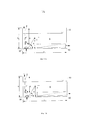
фиг. 1A - схематичный вид сбоку устройства для очистки воды в соответствии с первой формой выполнения,FIG. 1A is a schematic side view of a water treatment apparatus in accordance with a first embodiment,
фиг. 1B - схематичный вид сбоку устройства для очистки воды в соответствии со второй формой выполнения,FIG. 1B is a schematic side view of a water treatment apparatus in accordance with a second embodiment,
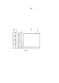
фиг. 2 - вид сверху устройства для очистки воды;FIG. 2 is a top view of a water purification device;
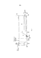
фиг. 3 - схематичный вид сбоку устройства для очистки воды в соответствии с третьей формой выполнения; иFIG. 3 is a schematic side view of a water treatment apparatus in accordance with a third embodiment; and
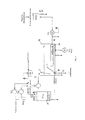
фиг. 4 - схематичное изображение способа в установке, включающей в себя устройство для очистки воды.FIG. 4 is a schematic illustration of a method in an apparatus including a water purifier.
Общая структура первой формы выполнения соответствующего изобретению устройства показана на фиг. 1а.The general structure of the first embodiment of the device according to the invention is shown in FIG. 1a.
Вид сбоку по фиг. 1a включает в себя резервуар 10, аэрационную установку 30, мембранный фильтрующий элемент 40, первый направляющий лоток 1 и второй направляющий лоток 2. Резервуар 10 имеет верхнюю сторону, которая открыта, и расположенную напротив этой открытой стороны поверхность дна. Аэрационная установка 30, первый направляющий лоток 1 и фильтрующий элемент 40 размещены продольно этой поверхности дна и на этой поверхности дна.The side view of FIG. 1a includes a
Резервуар 10 включает в себя наряду с верхней открытой стороной и поверхностью дна две противолежащие удлиненные боковые стенки и две противолежащие короткие боковые стенки. В целом резервуар 10 выполнен в виде прямоугольного параллелепипеда с длиной а, шириной b и высотой h. Удлиненные боковые стенки резервуара определяются длиной а и высотой h, в то время как размеры короткой боковой стенки устанавливаются шириной b и высотой h резервуара.The
В данной первой форме выполнения длина а составляет, например, 1 м, ширина b 0,61 м и высота h 0,5 м.In this first embodiment, the length a is, for example, 1 m, the width b 0.61 m and the height h 0.5 m.
Важно отметить, что эти размеры являются лишь примерными и выбраны в данном случае для того, чтобы описать и отобразить соответствующие пропорции и соотношения при расположении отдельных компонентов формы выполнения устройства относительно друг друга, причем в случае переноса модели пропорции отдельных компонентов могут быть одинаковыми или, по крайней мере, подобными друг другу. Кроме того следует указать на то, что при увеличении масштаба описанной формы выполнения устройства может учитываться гидравлическое подобие. Специалистам известны методы, позволяющие, исходя, например, из лабораторной установки или пилотной установки, произвести «up-scale» [англ. увеличение масштаба] установки и процесса.It is important to note that these dimensions are only approximate and are selected in this case in order to describe and display the appropriate proportions and ratios when the individual components of the device execution form are located relative to each other, and in case of model transfer, the proportions of the individual components can be the same or, according to at least similar to each other. In addition, it should be noted that when zooming in on the described embodiment of the device, hydraulic similarity can be taken into account. Specialists are aware of methods that allow, based, for example, from a laboratory installation or a pilot installation, to produce an “up-scale” [eng. zoom in] installation and process.
В случае, если резервуар 10 имеет указанные выше размеры, то аэрационная установка 30, состоящая из четырех отдельных аэрационных мембран, размещена на расстоянии, например, 0,1 м от первой короткой боковой стенки шириной b. Аэрационная установка 30 распространяется на всю ширину b резервуара 10 и может состоять из нескольких дисков, пластин, трубок или других геометрических форм.If the
Над этой аэрационной установкой 30 находится второй направляющий лоток 2, который также расположен на расстоянии 0,1 м от первой короткой боковой стенки и закреплен на кромках удлиненной стенки верхней открытой стороны резервуара 10. В показанном на фиг. 1A первом варианте второй направляющий лоток 2 размещен вертикально и соответственно параллельно первой короткой боковой стенке. Расстояние между поверхностью дна резервуара 10 и вторым направляющим лотком 2 составляет в данной форме выполнения 0,12 м.Above this
Если следовать длине стенки а резервуара 10, то в данной форме выполнения первый направляющий лоток 1 размещен на расстоянии, например, 0,2 м от первой короткой боковой стенки и закреплен на поверхности дна резервуара 10. Первый направляющий лоток 1 наклонен под углом α от 50 до 90°, например 60°, относительно поверхности дна резервуара 10 в сторону от первой короткой боковой стенки ко второй короткой боковой стенке резервуара 10. Соответственно расстояние между поверхностью дна резервуара 10 и верхней кромкой первого направляющего лотка 1 из-за уклона составляет, например, 0,26 м.If you follow the length of the wall a of the
В направлении взгляда от первой короткой боковой стенки вдоль длины а резервуара 10 за первым направляющим лотком 1 размещен фильтрующий элемент 40 на расстоянии, например, 0,39 м от первой короткой боковой стенки. Мембранный фильтрующий элемент 40 распространяется продольно поверхности дна до второй короткой боковой стенки и, таким образом, имеет длину, например, 0,61 м. В случае показанной здесь формы выполнения высота фильтрующего устройства составляет, например, 0,14 м, а высота уровня заполнения резервуара 10, например, 0,33 м. Соответственно фильтрующий элемент полностью погружен в находящуюся в резервуаре 10 жидкость.In the direction of view from the first short side wall along the length a of the
Показанная на фиг. 1B вторая форма выполнения соответствует по существу показанной на фиг. 1A первой форме выполнения, так что далее можно в полном объеме ссылаться на рассуждения относительно первой формы выполнения.Shown in FIG. 1B, the second embodiment corresponds essentially to that shown in FIG. 1A of the first embodiment, so that further discussion of the first embodiment can be made in full.
Вторая форма выполнения по фиг. 1B отличается от первой формы выполнения по фиг. 1A лишь относительно угла наклона второго направляющего лотка 2. Второй направляющий лоток 2, закрепленный на верхних кромках стенок резервуара 10, в случае второй формы выполнения наклонен под углом β 70-90°, предпочтительно 80° относительно противолежащей поверхности дна открытой стороны резервуара 10 в сторонупервой короткой боковой стенки резервуара 10. По причине наклона второго направляющего лотка 2 расстояние между первой короткой боковой стенкой и нижним концом второго направляющего лотка 2 сокращается и соответственно уменьшается ширина зазора для протекания введенной перемешанной с флокулянтом воды. А это в свою очередь повышает скорость потока флокулирующой смеси.The second embodiment of FIG. 1B differs from the first embodiment of FIG. 1A only with respect to the angle of inclination of the
Фиг. 2 показывает вид сверху представленной на фиг. 1 первой формы выполнения, причем в данном случае размещение четырех керамических аэрационных мембран на поверхности дна аэрационного резервуара 10 поясняется относительно размещения первого и второго направляющего лотка 1, 2. Четыре керамических аэрационных мембраны размещены параллельно вдоль первой короткой боковой стенки в пределах расстояния 0,1 м от упомянутой первой короткой боковой стенки. Диаметр каждой из аэрационных мембран составляет в данном случае 0,15 м, но может и отклоняться от этих размеров.FIG. 2 shows a top view of FIG. 1 of the first embodiment, and in this case, the placement of four ceramic aeration membranes on the bottom surface of the
Фиг. 3 показывает дальнейшую предпочтительную форму выполнения данного устройства. В отличие от показанных на фиг. 1A, B форм выполнения, в которых флокуляционая установка 20 размещается пространственно отделенной от резервуара 10 (не показано), в изображенной на фиг. 3 форме выполнения флокуляционая установка 20 интегрирована в резервуар 10.FIG. 3 shows a further preferred embodiment of this device. In contrast to those shown in FIG. 1A, B of the embodiments in which the
При этом предусматривается флокуляционая камера или отсек 20 резервуара 10, куда подается очищаемая вода и флокулянт.In this case, a flocculation chamber or
После перемешивания очищаемой воды с флокулянтом, например, с применением смесителя, смесь в верхнем отделе флокуляционого отсека 20 над перегородкой может быть введена в еще один отделенный от самой флотационной камеры 10 отсек 21, в котором может быть добавлено еще одно вспомогательное средство для флокуляции. Соответственно предусмотренная между флокуляционым отсеком 20 и отсеком 21 для внесения дальнейшего вспомогательного средства для флокуляции перегородка может иметь такую высоту, которая позволяет переносить перемешанную с флокулянтом воду из флокуляционого отсека 20 в отсек 21.After mixing the purified water with the flocculant, for example, using a mixer, the mixture in the upper section of the
После добавки других вспомогательных средств для флокуляции в отсеке 21 очищаемая вода проводится сверху вниз в отсеке 21 и может затем на дне резервуара попасть в зону контакта K резервуара 10 и быть проведена через аэрационную установку 30. Соответственно, очищаемая вода в форме выполнения по фиг. 3 проводится в виде меандра из флокуляционого отсека 20 в отсек 21 и затем в зону контакта K флотационной камеры или резервуара 10.After the addition of other flocculation aids to the
В связи с фиг. 4 далее будет описана форма осуществления способа очистки воды с применением устройства в соответствии со второй формой выполнения.In connection with FIG. 4, an embodiment of a method for purifying water using a device in accordance with a second embodiment will be described.
В данном экспериментальном способе используется загрязненная вода, перемешанная с гуминовыми веществами.This experimental method uses contaminated water mixed with humic substances.
Совокупность органических веществ в загрязненной воде в данном случае моделируется гуминовыми веществами, которые и в природе возникают в результате нормального биологического разложения. Гуминовые вещества являются сложными молекулярными цепями из алкильных и ароматических единиц с функциональными группами, например, -COOH, -NH2 и -RSH. На основе ионизированных кислотных групп они образуют отрицательно заряженные макромолекулы.The totality of organic substances in contaminated water in this case is modeled by humic substances, which in nature also arise as a result of normal biological decomposition. Humic substances are complex molecular chains of alkyl and aromatic units with functional groups, for example, —COOH, —NH 2 and —RSH. Based on ionized acid groups, they form negatively charged macromolecules.
Для флокуляции содержащихся в воде гуминовых веществ в качестве осаждающих средств предполагаются прежде всего содержащие трехвалентные ионы железо- и алюминийсодержащие вещества, которые могут быть в жидком или твердом виде. В данном случае применяется твердый FeCl3 для изготовления жидкого осаждающего средства. Загрязненная вода соединяется с раствором, содержащим гуминовые кислоты, и затем перемешивается с применением статического смесителя в резервуаре для флокулирования 20 с раствором, содержащим FeCl3. В резервуаре для флокулирования 20 происходит флокуляция содержащихся в загрязненной воде гуминовых кислот при помощи флокулянта FeCl3.For flocculation of humic substances contained in water as precipitating agents, iron and aluminum-containing substances containing trivalent ions, which may be in liquid or solid form, are primarily intended. In this case, solid FeCl 3 is used to make a liquid precipitating agent. Contaminated water is combined with a solution containing humic acids, and then mixed using a static mixer in a
Перемешанная с FeCl3 загрязненная вода в данном экспериментальном способе затем вводится из резервуара для флокулирования 20 в разделительный резервуар или резервуар для аэрации 10 объемным потоком 400 литров в час. Ввод в резервуар 10 происходит в области между первой короткой боковой стенкой резервуара 10 и вторым направляющим лотком 2, то есть в области перед вторым направляющим лотком 2. Это может происходить сверху через открытую сторону резервуара 10 или также сбоку снизу в резервуар 10. При этом второй направляющий лоток 2 наклонен под углом β, например, 80°, в сторону короткой боковой стенки, так что в связи с уменьшением ширины зазора между боковой стенкой и вторым направляющим лотком происходит увеличение скорости течения введенной флокулирующой смеси в направлении размещенной на дне резервуара для аэрации 10 аэрационной мембраны 30.The contaminated water mixed with FeCl 3 in this experimental method is then introduced from the
Через аэрационную установку 30, которая в данном случае состоит из четырех отдельных аэрационных мембран, впрыскивается газ, в особенности воздух, причем происходит образование микроскопических пузырьков непосредственно во введенной, перемешанной с флокулянтом воде. Образованные таким образом агломераты флокул и пузырьков воздуха проводятся вдоль наклоненного первого направляющего лотка 1 в сторону поверхности содержащейся в резервуаре 10 жидкости и соответственно в осадочную зону S резервуара 10.Through the
Пузырьки, которые выделяются по центру газовой мембраны, в связи с тем, что облако пузырьков имеет свойство скапливаться, развивают меньшую скорость подъема, чем наружные. Чем выше газовая мембрана находится в воде, то есть чем больше находящийся в резервуаре 10 объем газовой мембраны, тем меньше скорость подъема вследствие меньшего диаметра пузырьков. В целом пузырьки выделяются относительно равномерно по всей поверхности мембраны. Чем выше установленное давление газа, тем возникает больше пузырьков, большего размера и более быстрых. При уменьшении входного зазора до 1 см, то есть проходного зазора для поступающей флокулирующой смеси, входная скорость флокулирующой смеси в зону контакта K резервуара 10 является величиной того же порядка, что и скорость подъема пузырьков, так что пузырьки не могут подниматься в области проходного зазора на левом крае резервуара.Bubbles that stand out in the center of the gas membrane, due to the fact that the cloud of bubbles has the ability to accumulate, develop a lower rate of rise than the outside. The higher the gas membrane is in the water, that is, the larger the volume of the gas membrane located in the
Благодаря присоединению микропузырьков к флокулированным органическим компонентам они поднимаются в направлении поверхности находящейся в резервуаре 10 жидкости и образуют на поверхности воды слой твердого вещества, который удаляется механически, например, с применением очистных приспособлений, например, скреперов. Под этим слоем твердого вещества в осадочной зоне S резервуара 10 находится очищенная вода. Предварительно очищенная таким образом вода отводится с применением насоса Е1 через погруженный фильтрующий элемент 40 и в качестве очищенной воды готова для дальнейшей переработки, например, для дальнейших процессов опреснения.Due to the attachment of microbubbles to the flocculated organic components, they rise in the direction of the surface of the liquid located in the
Для предотвращения засорения поверхности фильтрующего элемента 40 через снабженные отверстиями шланги непосредственно на поверхность фильтрующего элемента 40 может подаваться воздух, что приводит к механическому удалению отложений на поверхности фильтрующего элемента 40.To prevent clogging of the surface of the
Перечень ссылочных обозначенийReference List
1 первый направляющий лоток1 first guide tray
2 второй направляющий лоток2 second guide tray
10 резервуар10 tank
20 флокуляционая установка20 flocculation unit
21 отсек резервуара 10 для внесения других вспомогательных средств для флокуляции21 compartment of the
30 аэрационная установка30 aeration installation
40 мембранный фильтрующий элемент40 membrane filter element
K зона контакта резервуара 10K
S осадочная зона резервуара 10S sedimentary zone of the
α угол наклона первого направляющего лотка 1α angle of inclination of the
β угол наклона второго направляющего лотка 2β the angle of the
Claims (33)
Applications Claiming Priority (3)
| Application Number | Priority Date | Filing Date | Title |
|---|---|---|---|
| DE102012207731.6 | 2012-05-09 | ||
| DE201210207731 DE102012207731A1 (en) | 2012-05-09 | 2012-05-09 | Apparatus and method for the pre-purification of water, in particular seawater |
| PCT/EP2013/058079 WO2013167358A1 (en) | 2012-05-09 | 2013-04-18 | Device and method for purifying water with flotation |
Publications (2)
| Publication Number | Publication Date |
|---|---|
| RU2014143696A RU2014143696A (en) | 2016-07-10 |
| RU2630541C2 true RU2630541C2 (en) | 2017-09-11 |
Family
ID=48430669
Family Applications (1)
| Application Number | Title | Priority Date | Filing Date |
|---|---|---|---|
| RU2014143696A RU2630541C2 (en) | 2012-05-09 | 2013-04-18 | Saline water treatment device and method |
Country Status (15)
| Country | Link |
|---|---|
| US (1) | US10029925B2 (en) |
| EP (1) | EP2867174B1 (en) |
| AU (1) | AU2013258354B2 (en) |
| BR (1) | BR112014027304B1 (en) |
| CA (1) | CA2871966C (en) |
| DE (1) | DE102012207731A1 (en) |
| DK (1) | DK2867174T3 (en) |
| ES (1) | ES2599820T3 (en) |
| IN (1) | IN2014MN02465A (en) |
| MX (1) | MX358898B (en) |
| NO (1) | NO346436B1 (en) |
| PL (1) | PL2867174T3 (en) |
| PT (1) | PT2867174T (en) |
| RU (1) | RU2630541C2 (en) |
| WO (1) | WO2013167358A1 (en) |
Families Citing this family (11)
| Publication number | Priority date | Publication date | Assignee | Title |
|---|---|---|---|---|
| CA2964891C (en) | 2014-10-22 | 2021-11-09 | Koch Membrane Systems, Inc. | Membrane filter module with bundle-releasing gasification device |
| DE102015208694A1 (en) | 2015-05-11 | 2016-11-17 | Akvolution Gmbh | Apparatus and method for generating gas bubbles in a liquid |
| USD779632S1 (en) | 2015-08-10 | 2017-02-21 | Koch Membrane Systems, Inc. | Bundle body |
| TWI606884B (en) * | 2016-01-29 | 2017-12-01 | 慶鴻機電工業股份有限公司 | Recovery liquid processing equipment for metal processing machine and the method thereof |
| CN106673136A (en) * | 2016-12-21 | 2017-05-17 | 安徽金川活动坝科技有限公司 | Double-membrane method waste water apparatus based on flat ceramic membrane |
| PL238499B1 (en) | 2017-12-31 | 2021-08-30 | King Abdulaziz City Sci & Tech | System of water treatment and the method for cleaning filtering membranes |
| DE102018101895B3 (en) | 2018-01-29 | 2019-02-07 | Akvola Technologies GmbH | Apparatus and method for generating gas bubbles in a liquid |
| DE102018128600B4 (en) | 2018-11-14 | 2023-10-05 | Dawid Marek Slomski | Filter device and cleaning system |
| IT201900018404A1 (en) * | 2019-10-10 | 2021-04-10 | De Nora Water Tech Italy S R L | WASTEWATER TREATMENT APPARATUS |
| US11939233B2 (en) | 2021-12-10 | 2024-03-26 | Saudi Arabian Oil Company | Oil-water separation system using hydrophobic/hydrophilic materials for capacity increase and improving produced water quality |
| DE102023102053A1 (en) | 2023-01-27 | 2024-08-01 | GWT - German Water Treatment GmbH | Flotation filter with calcium-containing filter bed |
Citations (7)
| Publication number | Priority date | Publication date | Assignee | Title |
|---|---|---|---|---|
| WO1998031634A1 (en) * | 1997-01-15 | 1998-07-23 | Hans Eriksson | Method and apparatus for purifying a liquid by means of flotation |
| US20040217058A1 (en) * | 2002-12-19 | 2004-11-04 | Jason Cadera | Integrated dissolved air flotation and immersed membrane filtration apparatus and method for using same |
| WO2008013349A1 (en) * | 2006-07-26 | 2008-01-31 | Korea Institute Of Science And Technology | Silica or alumina ceramic diffuser for generating microbubbles, method for manufacturing the same and method for wastewater treatment using air- floatation process using the same |
| US20090211974A1 (en) * | 2005-09-09 | 2009-08-27 | Degremont | Water clarifying apparatus and implementing method |
| WO2009135277A2 (en) * | 2008-05-09 | 2009-11-12 | Oliveira Joao Carlos Gomes De | A changeable continuous flow modular system for the treatment of water streams |
| EA201070761A1 (en) * | 2007-12-19 | 2011-02-28 | Сауди Арабиан Ойл Компани | MEMBRANE BIOLOGICAL REACTOR SYSTEM BASED ON SUSPENDED GRANULATED ACTIVATED COAL AND METHOD |
| RU2421407C2 (en) * | 2005-09-30 | 2011-06-20 | ОуТиВи ЭсЭй | Method and device for water treatment |
Family Cites Families (13)
| Publication number | Priority date | Publication date | Assignee | Title |
|---|---|---|---|---|
| SE302103B (en) * | 1964-12-05 | 1968-07-01 | Purac Ab | |
| FI83864C (en) * | 1987-03-25 | 1991-09-10 | Oiva Suutarinen | FOERFARANDE FOER RENANDE AV EN VAETSKA FRAON FASTA OCH UPPLOESTA FOERORENINGAR MED ETT FLOTATIONSKLARNING-FLOCKNINGSFOERFARANDE. |
| FI86293C (en) * | 1989-04-28 | 1992-08-10 | Oiva Suutarinen | FOERFARANDE FOER RENING AV EN VAETSKA FRAON FASTA OCH UPPLOESTA FOERORENINGAR MEDELST ETT FLOTATIONSFILTRERINGSFOERFARANDE. |
| SE503894C2 (en) * | 1995-01-19 | 1996-09-30 | Norrtaelje Kommun | Device for distribution and dispersion of air saturated water |
| JPH10109091A (en) * | 1996-10-04 | 1998-04-28 | Chlorine Eng Corp Ltd | Treatment of water |
| DE19647512A1 (en) * | 1996-11-16 | 1998-05-20 | Damann Franz Josef | Mobile waste water treatment assembly |
| DE10118940A1 (en) * | 2001-04-18 | 2002-10-24 | Georgi Joachim | Physical chemistry process removes all particulate and microbiological impurities from drinking water |
| CA2527525A1 (en) | 2005-11-17 | 2007-05-17 | Hydroxyl Systems Inc. | Wastewater treatment system for a marine vessel |
| DE102007007894A1 (en) * | 2007-02-14 | 2008-08-21 | Technische Universität Berlin | Restoring optimal flow characteristics of membrane filter for membrane activation reactor during water treatment, by carrying out a cleaning process in reactor and seizing gradient and/or curve profile of decreasing permeability of filter |
| AT505282B1 (en) | 2007-10-03 | 2008-12-15 | Va Tech Wabag Gmbh | METHOD AND DEVICE FOR REDUCING BIOFOULING ON MEMBRANES OF PRESSURE-DRIVEN MEMBRANE SEPARATION METHOD |
| BRPI0903291A2 (en) | 2009-09-02 | 2011-05-10 | Evonik Degussa Brasil Ltda | process for purifying water flowing in a river or canal |
| EP2690070B1 (en) * | 2011-03-25 | 2016-12-14 | Doosan Heavy Industries & Construction Co., Ltd. | Dissolved-air flotation-type pretreatment apparatus |
| FR2995603B1 (en) * | 2012-09-19 | 2014-09-26 | Veolia Water Solutions & Tech | WATER TREATMENT METHOD COMPRISING A FLOTATION COMBINED WITH GRAVITY FILTRATION AND CORRESPONDING INSTALLATION |
-
2012
- 2012-05-09 DE DE201210207731 patent/DE102012207731A1/en not_active Withdrawn
-
2013
- 2013-04-18 ES ES13722305.3T patent/ES2599820T3/en active Active
- 2013-04-18 NO NO20141184A patent/NO346436B1/en unknown
- 2013-04-18 PL PL13722305T patent/PL2867174T3/en unknown
- 2013-04-18 RU RU2014143696A patent/RU2630541C2/en active
- 2013-04-18 BR BR112014027304-9A patent/BR112014027304B1/en active IP Right Grant
- 2013-04-18 EP EP13722305.3A patent/EP2867174B1/en active Active
- 2013-04-18 DK DK13722305.3T patent/DK2867174T3/en active
- 2013-04-18 CA CA2871966A patent/CA2871966C/en active Active
- 2013-04-18 MX MX2014013400A patent/MX358898B/en active IP Right Grant
- 2013-04-18 PT PT137223053T patent/PT2867174T/en unknown
- 2013-04-18 IN IN2465MUN2014 patent/IN2014MN02465A/en unknown
- 2013-04-18 AU AU2013258354A patent/AU2013258354B2/en active Active
- 2013-04-18 WO PCT/EP2013/058079 patent/WO2013167358A1/en active Application Filing
- 2013-04-18 US US14/397,556 patent/US10029925B2/en active Active
Patent Citations (7)
| Publication number | Priority date | Publication date | Assignee | Title |
|---|---|---|---|---|
| WO1998031634A1 (en) * | 1997-01-15 | 1998-07-23 | Hans Eriksson | Method and apparatus for purifying a liquid by means of flotation |
| US20040217058A1 (en) * | 2002-12-19 | 2004-11-04 | Jason Cadera | Integrated dissolved air flotation and immersed membrane filtration apparatus and method for using same |
| US20090211974A1 (en) * | 2005-09-09 | 2009-08-27 | Degremont | Water clarifying apparatus and implementing method |
| RU2421407C2 (en) * | 2005-09-30 | 2011-06-20 | ОуТиВи ЭсЭй | Method and device for water treatment |
| WO2008013349A1 (en) * | 2006-07-26 | 2008-01-31 | Korea Institute Of Science And Technology | Silica or alumina ceramic diffuser for generating microbubbles, method for manufacturing the same and method for wastewater treatment using air- floatation process using the same |
| EA201070761A1 (en) * | 2007-12-19 | 2011-02-28 | Сауди Арабиан Ойл Компани | MEMBRANE BIOLOGICAL REACTOR SYSTEM BASED ON SUSPENDED GRANULATED ACTIVATED COAL AND METHOD |
| WO2009135277A2 (en) * | 2008-05-09 | 2009-11-12 | Oliveira Joao Carlos Gomes De | A changeable continuous flow modular system for the treatment of water streams |
Also Published As
| Publication number | Publication date |
|---|---|
| US20150114910A1 (en) | 2015-04-30 |
| RU2014143696A (en) | 2016-07-10 |
| NO20141184A1 (en) | 2015-01-26 |
| DK2867174T3 (en) | 2017-01-02 |
| MX358898B (en) | 2018-09-07 |
| EP2867174B1 (en) | 2016-09-07 |
| AU2013258354A1 (en) | 2014-10-09 |
| WO2013167358A1 (en) | 2013-11-14 |
| IN2014MN02465A (en) | 2015-07-10 |
| EP2867174A1 (en) | 2015-05-06 |
| PT2867174T (en) | 2016-12-15 |
| AU2013258354B2 (en) | 2017-04-13 |
| US10029925B2 (en) | 2018-07-24 |
| PL2867174T3 (en) | 2017-02-28 |
| BR112014027304B1 (en) | 2020-12-15 |
| ES2599820T3 (en) | 2017-02-03 |
| NO346436B1 (en) | 2022-08-15 |
| CA2871966A1 (en) | 2013-11-14 |
| CA2871966C (en) | 2022-12-13 |
| DE102012207731A1 (en) | 2013-11-14 |
| BR112014027304A2 (en) | 2017-06-27 |
| MX2014013400A (en) | 2015-02-04 |
Similar Documents
| Publication | Publication Date | Title |
|---|---|---|
| RU2630541C2 (en) | Saline water treatment device and method | |
| Rezakazemi et al. | Membrane filtration of wastewater from gas and oil production | |
| JP5033130B2 (en) | Water purification apparatus and method of implementation | |
| Ghernaout et al. | Water reuse: Extenuating membrane fouling in membrane processes | |
| US20210363044A1 (en) | Treating Water | |
| AU2009310485A1 (en) | Method for the filtration of a bioreactor liquid from a bioreactor; cross-flow membrane module, and bioreactor membrane system | |
| CN204281479U (en) | A kind for the treatment of system of coating wastewater | |
| KR101539727B1 (en) | A total phosphorus removal device using electrocoagulation and electromagnet | |
| KR101732811B1 (en) | Energy saving Forward Osmosis-filtration hybrid Water treatment/seawater desalination system using big size polymer draw solute and method of Water treatment/seawater desalination using the same | |
| CN102452749B (en) | Process for preparing desalted water from iron and steel enterprises sewage with high conversion rate | |
| CN110078175A (en) | A kind of ultrafiltration and air-floating integral unit and application | |
| KR101521012B1 (en) | Dissolved Air Flotation Facility Coupled with Membrane Filtration System | |
| CN205653272U (en) | Water treatment device | |
| CN205892904U (en) | A integration equipment for automaticallying process sewage | |
| CN105254054B (en) | A kind of oil field extracted water multiple treating system and method | |
| KR101469634B1 (en) | Water treatment system use of tubular filter module | |
| KR101820602B1 (en) | Movable membrane filtration apparatus for purifying water and method for purifying water using the same | |
| JP2016093789A (en) | Water treatment method and water treatment system | |
| KR20130005504U (en) | Filtration apparatus having means for recovering filter material | |
| CN211644952U (en) | Water recycling treatment device for degreased silane wastewater | |
| CN205653276U (en) | Dense drainage reenrichment device of reverse osmosis | |
| JP6965154B2 (en) | Membrane filtration device | |
| Anuradha et al. | Physico-Chemical Pathways for Wastewater Effluents | |
| KR20160085982A (en) | Membrane filtration for advanced water treatment device using hydraulic head differential | |
| Peleka et al. | A hybrid flotation–microfiltration cell for metal ions recovery |
Legal Events
| Date | Code | Title | Description |
|---|---|---|---|
| HZ9A | Changing address for correspondence with an applicant |