RU2628639C1 - Device for detecting light signals and method for detecting light signals - Google Patents
Device for detecting light signals and method for detecting light signals Download PDFInfo
- Publication number
- RU2628639C1 RU2628639C1 RU2016139365A RU2016139365A RU2628639C1 RU 2628639 C1 RU2628639 C1 RU 2628639C1 RU 2016139365 A RU2016139365 A RU 2016139365A RU 2016139365 A RU2016139365 A RU 2016139365A RU 2628639 C1 RU2628639 C1 RU 2628639C1
- Authority
- RU
- Russia
- Prior art keywords
- traffic light
- phase
- power supply
- brightness
- supply system
- Prior art date
Links
Images


Classifications
-
- G—PHYSICS
- G06—COMPUTING; CALCULATING OR COUNTING
- G06V—IMAGE OR VIDEO RECOGNITION OR UNDERSTANDING
- G06V20/00—Scenes; Scene-specific elements
- G06V20/50—Context or environment of the image
- G06V20/56—Context or environment of the image exterior to a vehicle by using sensors mounted on the vehicle
- G06V20/58—Recognition of moving objects or obstacles, e.g. vehicles or pedestrians; Recognition of traffic objects, e.g. traffic signs, traffic lights or roads
- G06V20/584—Recognition of moving objects or obstacles, e.g. vehicles or pedestrians; Recognition of traffic objects, e.g. traffic signs, traffic lights or roads of vehicle lights or traffic lights
-
- B—PERFORMING OPERATIONS; TRANSPORTING
- B60—VEHICLES IN GENERAL
- B60W—CONJOINT CONTROL OF VEHICLE SUB-UNITS OF DIFFERENT TYPE OR DIFFERENT FUNCTION; CONTROL SYSTEMS SPECIALLY ADAPTED FOR HYBRID VEHICLES; ROAD VEHICLE DRIVE CONTROL SYSTEMS FOR PURPOSES NOT RELATED TO THE CONTROL OF A PARTICULAR SUB-UNIT
- B60W10/00—Conjoint control of vehicle sub-units of different type or different function
-
- G—PHYSICS
- G08—SIGNALLING
- G08G—TRAFFIC CONTROL SYSTEMS
- G08G1/00—Traffic control systems for road vehicles
- G08G1/16—Anti-collision systems
Abstract
Description
Область техники, к которой относится изобретениеFIELD OF THE INVENTION
[0001] Настоящее изобретение относится к устройству обнаружения светофоров и к способу обнаружения светофоров.[0001] The present invention relates to a device for detecting traffic lights and to a method for detecting traffic lights.
Уровень техникиState of the art
[0002] На сегодняшний день известно устройство обнаружения светофоров для обнаружения светофора из изображения, захваченного посредством камеры (см. патентный документ 1). Согласно патентному документу 1, часть, указывающая цвет сигнальной лампы, извлекается из изображения, вычисляется округлость, указывающая то, насколько близкой к идеальной окружности является извлеченная часть, и часть, имеющая более высокую округлость, обнаруживается в качестве возможного варианта для сигнальной лампы.[0002] Today, a traffic light detection device for detecting a traffic light from an image captured by a camera is known (see Patent Document 1). According to Patent Document 1, a part indicating the color of the signal lamp is extracted from the image, a roundness is calculated indicating how close to the ideal circle the extracted part is, and a part having a higher roundness is detected as a possible option for the signal lamp.
Список библиографических ссылокList of bibliographic references
Патентные документыPatent documents
[0003] Патентный документ 1. Публикация заявки на патент (Япония) номер 2005-301518[0003] Patent Document 1. Publication of Patent Application (Japan) No. 2005-301518
Сущность изобретенияSUMMARY OF THE INVENTION
[0004] Для обнаружения в качестве возможного варианта для сигнальной лампы, извлеченная часть должна иметь размер изображения, достаточно большой для определения округлости. Таким образом, технология в патентном документе 1 испытывает затруднения при точном обнаружении удаленного светофора, размер изображения которого является слишком небольшим для того, чтобы определять округлость.[0004] In order to be detected as a possible option for a warning light, the extracted part should have an image size large enough to determine roundness. Thus, the technology in Patent Document 1 has difficulty accurately detecting a remote traffic light whose image size is too small to determine roundness.
[0005] Настоящее изобретение осуществлено с учетом вышеизложенной проблемы, и его цель заключается в том, чтобы предоставлять устройство обнаружения светофоров и способ обнаружения светофоров, допускающие обнаружение даже удаленного светофора с высокой точностью.[0005] The present invention has been made in view of the foregoing problem, and its purpose is to provide a traffic light detection device and a traffic light detection method capable of detecting even a remote traffic light with high accuracy.
[0006] Устройство обнаружения светофоров согласно аспекту настоящего изобретения включает в себя модуль захвата изображений, сконфигурированный с возможностью многократно захватывать изображение окрестности транспортного средства, чтобы получать последовательность из нескольких изображений, и модуль обнаружения светофоров, сконфигурированный с возможностью обнаруживать светофор из изображений. Модуль обнаружения светофоров обнаруживает информацию фазы системы энергоснабжения, используемой в области вокруг транспортного средства, включающей в себя светофор, из цикла варьирования яркости в последовательности из нескольких изображений и извлекает из изображений синхронизированный пиксел с яркостью, которая варьируется синхронно с циклом переменного тока электроэнергии, подаваемой в светофор, посредством использования информации фазы системы энергоснабжения. Устройство обнаружения светофоров определяет, из синхронизированного пиксела, то, присутствует или нет светофор.[0006] A traffic light detecting device according to an aspect of the present invention includes an image pickup module configured to repeatedly capture an image of a vehicle vicinity to obtain a sequence of several images, and a traffic light detection module configured to detect a traffic light from images. The traffic light detection module detects phase information of a power supply system used in an area around a vehicle including a traffic light from a cycle of varying brightness in a sequence of several images and extracts a synchronized pixel from the images with a brightness that varies synchronously with the alternating current cycle of the electric power supplied to traffic light by using phase information of a power supply system. The traffic light detection device determines from the synchronized pixel whether or not a traffic light is present.
Краткое описание чертежейBrief Description of the Drawings
[0007] Фиг.1 является блок-схемой, иллюстрирующей общую конфигурацию устройства обнаружения светофоров согласно варианту осуществления настоящего изобретения;[0007] FIG. 1 is a block diagram illustrating a general configuration of a traffic light detection apparatus according to an embodiment of the present invention;
Фиг.2 является блок-схемой, иллюстрирующей подробную конфигурацию модуля 15 формирования синхронизированных изображений, проиллюстрированного на фиг.1;FIG. 2 is a block diagram illustrating a detailed configuration of a synchronized
Фиг.3(a) является графиком, иллюстрирующим разность в диапазоне варьирования яркости в зависимости от расстояния от транспортного средства, а фиг.3(b) является примером изображения, снятого камерой, иллюстрирующим уличный светильник 31a, торговый автомат 31b и вывеску 31c в качестве примеров других видов электрического освещения, расположенных около транспортного средства, и иллюстрирующим светофоры 32 и 33, удаленные от транспортного средства;FIG. 3 (a) is a graph illustrating a difference in a brightness variation range depending on a distance from a vehicle, and FIG. 3 (b) is an example of a camera image illustrating a
Фиг.4 является блок-схемой, иллюстрирующей модификацию модуля 19 обнаружения фазы;4 is a block diagram illustrating a modification of a
Фиг.5 является схемой, иллюстрирующей пример изображения, снятого камерой, захваченного, когда транспортное средство движется в туннеле;5 is a diagram illustrating an example of an image captured by a camera captured when a vehicle is moving in a tunnel;
Фиг.6 является блок-схемой последовательности операций, иллюстрирующей пример способа обнаружения светофоров с использованием устройства обнаружения светофоров, проиллюстрированного на фиг.1;FIG. 6 is a flowchart illustrating an example of a traffic light detection method using the traffic light detection apparatus illustrated in FIG. 1;
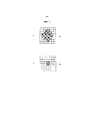
Фиг.7(a) является схемой, указывающей необходимый размер пиксельной группы 53a, чтобы обнаруживать возможный вариант для сигнальной лампы из округлости, а фиг.7(b) является схемой, указывающей число синхронизированных пикселов 53b, которые могут обнаруживаться в варианте осуществления; иFig. 7 (a) is a diagram indicating the required size of the
Фиг.8 иллюстрирует разность в корреляционных значениях между тем, когда фаза опорного сигнала синхронизирована и не синхронизирована, фиг.8(a) иллюстрирует состояние, в котором фаза опорного сигнала синхронизирована с фазой электроэнергии, а фиг.8(b) иллюстрирует состояние, в котором фаза опорного сигнала инвертируется относительно фазы электроэнергии.Fig. 8 illustrates the difference in correlation values between when the phase of the reference signal is synchronized and not synchronized, Fig. 8 (a) illustrates the state in which the phase of the reference signal is synchronized with the phase of electric power, and Fig. 8 (b) illustrates the state in wherein the phase of the reference signal is inverted with respect to the phase of the electric power.
Подробное описание вариантов осуществленияDetailed Description of Embodiments
[0008] Со ссылкой на чертежи, предоставляется описание варианта осуществления. На чертежах, идентичные части обозначаются посредством идентичных ссылок с номерами, и их описание опускается.[0008] With reference to the drawings, a description of an embodiment is provided. In the drawings, identical parts are denoted by identical reference numbers, and their description is omitted.
[0009] Со ссылкой на фиг.1, ниже приводится описание общей конфигурации устройства обнаружения светофоров согласно варианту осуществления. Устройство обнаружения светофоров монтируется на транспортном средстве и включает в себя модуль 11 захвата изображений для захвата изображения окрестности транспортного средства многократно с предварительно определенным временным интервалом, чтобы получать последовательность из нескольких изображений (кадров), и модуль 12 обнаружения светофоров для обнаружения светофора из изображений, захваченных посредством модуля 11 захвата изображений.[0009] With reference to FIG. 1, a general configuration of a traffic light detection apparatus according to an embodiment is described below. The traffic light detection device is mounted on a vehicle and includes an image capturing module 11 for capturing an image of a vehicle neighborhood repeatedly with a predetermined time interval to obtain a sequence of several images (frames), and a traffic
[0010] Модуль 11 захвата изображений представляет собой цифровую камеру с использованием полупроводникового датчика изображений, например, CCD или CMOS, которая получает цифровое изображение, для которого может выполняться обработка изображений. Цифровая камера включает в себя широкоугольную линзу, имеющую широкий угол обзора. Диапазон формирования изображений (угол обзора) модуля 11 захвата изображений включает в себя направление движения транспортного средства и обочины дороги в направлениях вправо и влево около транспортного средства.[0010] The image capturing unit 11 is a digital camera using a semiconductor image sensor, such as a CCD or CMOS, which receives a digital image for which image processing can be performed. The digital camera includes a wide-angle lens having a wide viewing angle. The imaging range (viewing angle) of the image capturing unit 11 includes the direction of travel of the vehicle and the roadside in the right and left directions near the vehicle.
[0011] Модуль 12 обнаружения светофоров принимает изображения (в дальнейшем называемые "изображениями, снятыми камерой"), полученные посредством модуля 11 захвата изображений, и обнаруживает позицию светофора в изображениях, снятых камерой. Позиционная информация обнаруженного светофора передается в другое функциональное обрабатывающее устройство (CPU 13 транспортного средства), смонтированное на транспортном средстве, которое включает в себя, например, контроллер, чтобы выполнять автоматизированное приведение в движение транспортного средства. Модуль 12 обнаружения светофоров включает в себя микроконтроллер, включающий в себя, например, CPU, запоминающее устройство 25 и модуль ввода-вывода, которые служат в качестве нескольких модулей обработки информации, включенных в устройство обнаружения светофоров посредством выполнения компьютерной программы, установленной заранее. Модуль 12 обнаружения светофоров многократно выполняет последовательность информационных процессов для каждой последовательности из нескольких изображений, снятых камерой (кадров), чтобы обнаруживать позицию светофора из изображений, снятых камерой. Модуль 12 обнаружения светофоров может быть включен в ECU, который также используется для другого управления транспортным средством.[0011] The traffic
[0012] Несколько модулей обработки информации, служащих в качестве модуля 12 обнаружения светофоров, включают в себя модуль 19 обнаружения фазы, модуль 15 формирования синхронизированных изображений и модуль 18 определения светофоров.[0012] Several information processing modules serving as a traffic
[0013] Запоминающее устройство 25 сохраняет последовательность из нескольких изображений 28, снятых камерой (кадров) за раз. Например, запоминающее устройство 25 сохраняет несколько изображений 28, снятых камерой, за раз, которые захватываются в течение одного цикла переменного тока электроэнергии, подаваемой в светофоры.[0013] The
[0014] Модуль 19 обнаружения фазы обнаруживает информацию фазы системы энергоснабжения, используемой в области вокруг транспортного средства, включающей в себя светофор, из цикла варьирования яркости в последовательности из нескольких изображений 28. Информация фазы системы энергоснабжения около светофора, как правило, является общей между сигнальными лампами и другими видами электрического освещения, расположенными вокруг светофора. Другими словами, фаза электроэнергии, подаваемой в другие виды электрического освещения, расположенные вокруг светофора, в общем, является идентичной фазе электроэнергии, подаваемой в светофоры. Следовательно, модуль 19 обнаружения фазы может обнаруживать информацию фазы электроэнергии, подаваемой в светофоры, из цикла варьирования яркости изображений 28, снятых камерой. Следует отметить, что "информация фазы системы энергоснабжения" означает информацию фазы сети общего пользования.[0014] The
[0015] Например, фиг.3(a) является графиком, иллюстрирующим разность в диапазоне варьирования яркости в зависимости от расстояния от транспортного средства, а фиг.3(b) является схемой, иллюстрирующей уличный светильник 31a, торговый автомат 31b и вывеску 31c в качестве примеров других видов электрического освещения, расположенных около транспортного средства, а также иллюстрирующей светофоры 32 и 33, удаленные от транспортного средства. Фиг.3(a) иллюстрирует варьирования яркости уличного светильника 31a и светофоров 32 и 33, проиллюстрированных на фиг.3(b). Диапазоны варьирований яркости других видов электрического освещения (уличного светильника 31a, торгового автомата 31b и вывески 31c), расположенных около транспортного средства, превышают диапазоны варьирований яркости удаленных светофоров (32, 33). Помимо этого, чем больше диапазон варьирования яркости, тем больше повышается точность обнаружения информации фазы. Следовательно, можно обнаруживать с высокой точностью информацию фазы электроэнергии, подаваемой в удаленные светофоры (32, 33), из цикла варьирований яркости других видов (31a-31c) электрического освещения, расположенных около транспортного средства.[0015] For example, FIG. 3 (a) is a graph illustrating a difference in a range of varying brightness depending on a distance from a vehicle, and FIG. 3 (b) is a diagram illustrating a
[0016] Альтернативно, модуль 19 обнаружения фазы может выбирать пиксел, имеющий наибольший диапазон варьирования яркости из всех пикселов изображений, снятых камерой, и обнаруживать информацию фазы системы энергоснабжения с использованием выбранного пиксела. Это делает точность обнаружения информации фазы наибольшей. Кроме того, модуль 19 обнаружения фазы может обнаруживать информацию фазы системы энергоснабжения посредством умножения между собой пикселов, имеющих относительно больший диапазон варьирования яркости.[0016] Alternatively, the
[0017] Следует отметить, что ниже описывается модификация модуля 19 обнаружения фазы со ссылкой на фиг.4, которая эффективно обнаруживает варьирование яркости других видов (31a-31c) электрического освещения, расположенных около транспортного средства, из текущей позиции транспортного средства и картографической информации области вокруг транспортного средства.[0017] It should be noted that a modification of the
[0018] Модуль 15 формирования синхронизированных изображений извлекает из изображений, снятых камерой, синхронизированный пиксел с яркостью, которая варьируется синхронно с циклом переменного тока электроэнергии, подаваемой в светофоры, с использованием информации фазы системы энергоснабжения, обнаруженной посредством модуля 19 обнаружения фазы, и формирует синхронизированные изображения, включающие в себя извлеченный синхронизированный пиксел. Например, модуль 15 формирования синхронизированных изображений формирует опорный сигнал, синхронизированный с фазой электроэнергии, подаваемой в светофоры, с использованием информации фазы системы энергоснабжения, и выполняет процесс обнаружения синхронизации для умножения между собой опорного сигнала и сигнала яркости каждого пиксела изображений, снятых камерой. Из этого процесса, извлекается синхронизированный пиксел с яркостью, которая варьируется синхронно с циклом переменного тока электроэнергии, подаваемой в светофоры.[0018] The synchronized
[0019] Электроэнергия, подаваемая в светофоры, представляет собой мощность переменного тока, полученную посредством двухполупериодного выпрямления электроэнергии из сети общего пользования. Яркость сигнальной лампы, которая загорается посредством приема подачи электроэнергии из сети общего пользования, варьируется с циклом, идентичным циклу (например, 100 Гц) двухполупериодной выпрямленной мощности переменного тока. По этой причине, можно обнаруживать сигнальную лампу, которая загорается посредством приема подачи электроэнергии из сети общего пользования, посредством извлечения, из изображений, снятых камерой, синхронизированного пиксела с яркостью, которая варьируется синхронно с циклом переменного тока электроэнергии, подаваемой в светофоры. Ниже описываются конкретные процессы со ссылкой на фиг.2 и 8.[0019] The electric power supplied to the traffic lights is an alternating current power obtained by half-wave rectifying the electric power from the public network. The brightness of the signal lamp, which lights up by receiving power from the public network, varies with a cycle identical to the cycle (for example, 100 Hz) of a half-wave rectified AC power. For this reason, it is possible to detect a signal lamp that lights up by receiving a power supply from the public network, by extracting, from the images captured by the camera, a synchronized pixel with a brightness that varies synchronously with the alternating current cycle of the electric power supplied to the traffic lights. Specific processes are described below with reference to FIGS. 2 and 8.
[0020] Когда оттенок синхронизированного пиксела, извлеченного посредством модуля 15 формирования синхронизированных изображений, является аналогичным оттенку цвета сигнала, модуль 18 определения светофоров определяет то, что светофор присутствует в позиции синхронизированного пиксела. Виды электрического освещения, которые загораются посредством приема подачи электроэнергии из сети общего пользования, включают в себя не только сигнальные лампы светофоров, но также и другие виды электрического освещения, которые загораются на дороге, такие как уличный светильник 31a, торговый автомат 31b и вывеска 31c, как проиллюстрировано на фиг.3(b). Синхронизированные пикселы, извлеченные посредством модуля 15 формирования синхронизированных изображений, могут включать в себя пикселы, извлеченных из этих других видов электрического освещения. Посредством определения модулем 18 определения светофоров подобия в оттенке между синхронизированными пикселами и цветами сигнала, можно исключать эти другие виды электрического освещения из результата извлечения, выполняемого посредством модуля 15 формирования синхронизированных изображений.[0020] When the hue of the synchronized pixel extracted by the synchronized
[0021] Здесь, модуль 18 определения светофоров может быть выполнен с возможностью определять то, присутствует или нет светофор, с использованием позиции в изображениях и яркости синхронизированного пиксела, вместо использования модуля определения оттенка, который определяет то, является или нет оттенок синхронизированного пиксела аналогичным оттенку цвета сигнала. Посредством определения позиций светофоров в изображениях из картографической информации по окрестности транспортного средства и сопоставления определенных позиций с позицией синхронизированного пиксела, можно исключать эти другие виды электрического освещения. Помимо этого, посредством оценки яркости светофора в изображениях из расстояния от транспортного средства до светофора, также можно определять то, что светофор присутствует в синхронизированном пикселе, имеющем яркость в пределах оценки.[0021] Here, the traffic
[0022] Модуль 12 обнаружения светофоров выводит в CPU 13 транспортного средства позиционную информацию пиксельной группы, в которой модуль 18 определения светофоров определяет то, что светофор присутствует.[0022] The traffic
[0023] Далее, со ссылкой на фиг.2 и 8, подробно описывается модуль 15 формирования синхронизированных изображений. Во-первых, со ссылкой на фиг.2, подробно описывается конфигурация модуля 15 формирования синхронизированных изображений. Модуль 15 формирования синхронизированных изображений включает в себя модуль 26 умножения, фильтр 20 нижних частот (LPF) и модуль 17 формирования опорных сигналов.[0023] Next, with reference to FIGS. 2 and 8, a synchronized
[0024] Модуль 17 формирования опорных сигналов формирует опорный сигнал, синхронизированный с фазой электроэнергии, подаваемой в светофоры, с использованием информации фазы системы энергоснабжения (сети общего пользования). Модуль 26 умножения умножает между собой опорный сигнал и сигнал яркости каждого пиксела изображений 28, снятых камерой (кадров), считываемых из запоминающего устройства 25. Модуль 26 умножения выполняет вышеуказанное умножение для каждого из изображений, снятых камерой, сохраненных за раз в запоминающем устройстве 25. LPF 20 извлекает только низкочастотные компоненты посредством сокращения уровней частотных компонентов выше предварительно определенной частоты отсечки из результатов умножения посредством модуля 26 умножения и выводит синхронизированное изображение, включающее в себя синхронизированный пиксел.[0024] The reference
[0025] Со ссылкой на фиг.8(a) и 8(b), описывается согласование фазы опорного сигнала. Фиг.8(a) иллюстрирует состояние, в котором фаза опорного сигнала согласовывается с фазой электроэнергии, подаваемой в светофоры. Посредством умножения между собой 1) сигнала яркости каждого пиксела и 2) опорного сигнала в этом состоянии, 3) сигнал после умножения, т.е. яркость синхронизированного пиксела и среднее значение (корреляционное значение G1) яркости синхронизированного пиксела, становится наибольшим.[0025] With reference to FIGS. 8 (a) and 8 (b), phase matching of the reference signal is described. Fig. 8 (a) illustrates a state in which the phase of the reference signal is matched with the phase of the electric power supplied to the traffic lights. By multiplying among themselves 1) the brightness signal of each pixel and 2) the reference signal in this state, 3) the signal after multiplication, i.e. the brightness of the synchronized pixel and the average value (correlation value G1) of the brightness of the synchronized pixel becomes the largest.
[0026] Напротив, фиг.8(b) иллюстрирует состояние, в котором фаза опорного сигнала инвертируется относительно фазы электроэнергии, подаваемой в светофоры. Посредством умножения между собой 1) сигнала яркости каждого пиксела и 2) опорного сигнала в этом состоянии, 3) сигнал после умножения, т.е. яркость синхронизированного пиксела и среднее значение (корреляционное значение G2) яркости синхронизированного пиксела, становится наименьшим.[0026] In contrast, FIG. 8 (b) illustrates a state in which a phase of a reference signal is inverted with respect to a phase of electric power supplied to traffic lights. By multiplying among themselves 1) the brightness signal of each pixel and 2) the reference signal in this state, 3) the signal after multiplication, i.e. the brightness of the synchronized pixel and the average value (correlation value G2) of the brightness of the synchronized pixel becomes the smallest.
[0027] Как проиллюстрировано на фиг.3, по мере того, как расстояния от транспортного средства до светофоров (32, 33) становятся большими, яркость сигнальной лампы, обнаруженная посредством модуля 11 захвата изображений, становится более низкой, и диапазон варьирования яркости становится меньшим. Чтобы разрешать это, посредством приближения фазы опорного сигнала к фазе варьирования яркости сигнальной лампы, т.е. к фазе электроэнергии, подаваемой в светофоры, можно получать высокое корреляционное значение (G1), которое, в свою очередь, позволяет обнаруживать удаленные светофоры с высокой точностью.[0027] As illustrated in FIG. 3, as the distances from the vehicle to the traffic lights (32, 33) become large, the brightness of the signal lamp detected by the image pickup unit 11 becomes lower, and the range of variation in brightness becomes smaller . To solve this, by approximating the phase of the reference signal to the phase of varying the brightness of the signal lamp, i.e. to the phase of the electricity supplied to the traffic lights, it is possible to obtain a high correlation value (G1), which, in turn, allows you to detect remote traffic lights with high accuracy.
[0028] В варианте осуществления, посредством использования информации фазы системы энергоснабжения, используемой в области вокруг транспортного средства, включающей в себя светофор, модуль 19 обнаружения фазы обнаруживает фазу электроэнергии, подаваемой в светофоры, с высокой точностью. Это позволяет приближать фазу опорного сигнала к фазе варьирования яркости сигнальной лампы, т.е. к фазе электроэнергии, подаваемой в светофоры.[0028] In an embodiment, by using the phase information of the power supply system used in the area around the vehicle including the traffic light, the
[0029] Со ссылкой на фиг.4, описывается модификация модуля 19 обнаружения фазы. Модуль 19 обнаружения фазы включает в себя модуль 35 определения состояний дороги, модуль 36 задания областей изображения и модуль 37 извлечения фазы.[0029] With reference to FIG. 4, a modification of a
[0030] Модуль 35 определения состояний дороги определяет состояние дороги на основе информации относительно текущей позиции транспортного средства и картографической информации по окрестностям, полученной снаружи или изнутри транспортного средства с использованием GPS-функции и картографической базы данных. Например, модуль 35 определения состояний дороги определяет то, форма дороги в направлении движения транспортного средства представляет собой прямую линию, как проиллюстрировано на фиг.3(b), либо изгиб вправо или влево. Модуль 35 определения состояний дороги также определяет то, движется или нет транспортное средство в туннеле, как проиллюстрировано на фиг.5.[0030] The road
[0031] Модуль 36 задания областей изображения задает область изображения в каждом изображении, снятом камерой, на основе состояния дороги, определенного посредством модуля 35 определения состояний дороги. Например, когда форма дороги представляет собой прямую линию, модуль 36 задания областей изображения задает области (R2, R3), в которых изображения обочин дороги для дороги захватываются в изображениях, снятых камерой, в качестве областей изображения, как проиллюстрировано на фиг.3(b). Это приводит к тому, что области изображения включают в себя другие виды электрического освещения (31a, 31b, 31c), расположенные на обочине дороги для дороги. Дополнительно, когда транспортное средство движется в туннеле, модуль 36 задания областей изображения задает в изображениях, снятых камерой, область R4, в которой захватываются осветительные лампы 34, установленные на внутренней стенке туннеля, в качестве области изображения, как проиллюстрировано на фиг.5.[0031] The image
[0032] Модуль 37 извлечения фазы извлекает информацию фазы системы энергоснабжения из областей (R2-R4) изображения, заданных посредством модуля 36 задания областей изображения. Можно в зависимости от состояния дороги идентифицировать область изображения, в которой оценивается то, что присутствует свет, имеющий большое варьирование яркости, что позволяет эффективно обнаруживать варьирования яркости других видов (31a-31c и 34) электрического освещения, расположенных около транспортного средства.[0032] The
[0033] Далее описывается способ обнаружения светофоров с использованием устройства обнаружения светофоров, проиллюстрированного на фиг.1, со ссылкой на фиг.6. Работа устройства обнаружения светофоров, проиллюстрированного на блок-схеме последовательности операций способа по фиг.6, начинается, как только включается переключатель зажигания транспортного средства, и активируется устройство обнаружения светофоров, и она многократно выполняется до тех пор, пока устройство обнаружения светофоров не прекращает работу.[0033] The following describes a method for detecting traffic lights using the traffic light detection device illustrated in FIG. 1 with reference to FIG. 6. The operation of the traffic light detection device illustrated in the flowchart of FIG. 6 starts as soon as the vehicle’s ignition switch is turned on and the traffic light detection device is activated, and it is repeatedly executed until the traffic light detection device stops working.
[0034] На этапе S01, модуль 11 захвата изображений многократно захватывает изображения окрестности транспортного средства и получает последовательность из нескольких изображений, снятых камерой. Модуль 11 захвата изображений захватывает изображения многократно в течение одного цикла переменного тока электроэнергии, подаваемой в светофоры. Полученные данные изображений передаются в модуль 15 формирования синхронизированных изображений и временно сохраняются в запоминающем устройстве 25.[0034] In step S01, the image pickup unit 11 repeatedly captures images of a neighborhood of the vehicle and obtains a sequence of several images captured by the camera. The image capturing unit 11 captures images multiple times during one alternating current cycle of the electric power supplied to the traffic lights. The obtained image data is transmitted to the synchronized
[0035] На этапах от S03 до S07, модуль 19 обнаружения фазы обнаруживает информацию фазы системы энергоснабжения, используемой в области вокруг транспортного средства, включающей в себя светофор, из цикла варьирования яркости в последовательности из нескольких изображений 28, снятых камерой. В качестве примера, модуль 19 обнаружения фазы обнаруживает информацию фазы системы энергоснабжения в зависимости от того, становится или нет диапазон (ΔD) варьирования яркости пикселов, включенных в изображения 28, снятые камерой, больше предварительно определенного порогового значения (Th). Для областей (R2-R4) изображения, заданных посредством модуля 36 задания областей изображения, модуля 19 обнаружения фазы согласно модификации, проиллюстрированной на фиг.4, может определять то, становится или нет диапазон (ΔD) варьирования яркости больше предварительно определенного порогового значения (Th), как и следовало ожидать.[0035] In steps S03 to S07, the
[0036] Во-первых, на этапе S03, модуль 19 обнаружения фазы выбирает некоторый пиксел из изображений 28, снятых камерой, и определяет то, превышает или нет диапазон (ΔD) варьирования яркости пиксела предварительно определенное пороговое значение (Th). Когда диапазон (ΔD) превышает предварительно определенное пороговое значение (Th) ("Да" на S03), можно точно обнаруживать информацию фазы из изображений 28, снятых камерой. Затем обработка переходит к этапу 05, на котором модуль 19 обнаружения фазы измеряет фазу варьирования яркости выбранного пиксела. Модуль 19 обнаружения фазы задает измеренную фазу (этап S07).[0036] First, in step S03, the
[0037] С другой стороны, когда диапазон (ΔD) не превышает предварительно определенное пороговое значение (Th) ("Нет" на S03), невозможно точно обнаруживать информацию фазы из изображений 28, снятых камерой. Следовательно, обработка переходит к этапу 09, на котором модуль 19 обнаружения фазы задает предварительно определенную опорную фазу. В качестве предварительно определенной опорной фазы, может использоваться фаза, измеренная на этапе S05 контура управления в одно или более предыдущих времен.[0037] On the other hand, when the range (ΔD) does not exceed a predetermined threshold value (Th) (“No” in S03), it is not possible to accurately detect phase information from
[0038] Обработка переходит к этапу S11, на котором модуль 17 формирования опорных сигналов формирует опорный сигнал на основе заданной фазы (S07) или заданного опорного сигнала (S09). Обработка переходит к этапу S13, на котором модуль 26 умножения выполняет процесс обнаружения синхронизации для умножения между собой опорного сигнала и сигнала яркости каждого пиксела в изображениях, снятых камерой. Затем синхронизированный пиксел извлекается из низкочастотного сигнала, полученного посредством фильтрации с использованием LPF 20.[0038] The processing proceeds to step S11, in which the reference
[0039] Обработка переходит к этапу S15, на котором модуль 18 определения светофоров определяет то, является или нет оттенок синхронизированного пиксела, извлеченного посредством модуля 15 формирования синхронизированных изображений, аналогичным оттенку цвета сигнала. Когда оттенок синхронизированного пиксела является аналогичным оттенку цвета сигнала, можно определять то, что светофор присутствует в позиции синхронизированного пиксела. Следовательно, обработка переходит к этапу S17, и модуль 18 определения светофоров помечает синхронизированный пиксел в качестве светофора. С другой стороны, когда оттенок синхронизированного пиксела не является аналогичным оттенку цвета сигнала ("Нет" на S15), можно определять то, что один из других видов электрического освещения присутствует в позиции синхронизированного пиксела вместо сигнальной лампы. Следовательно, обработка переходит к этапу S19, и модуль 18 определения светофоров помечает синхронизированный пиксел в качестве одного из других видов электрического освещения.[0039] The processing proceeds to step S15 where the traffic
[0040] Обработка переходит к этапу S21, на котором модуль 18 определения светофоров определяет то, выполнены или нет определения для всех синхронизированных пикселов, извлеченных на этапе S13, в отношении того, указывает или нет каждый из синхронизированных пикселов светофор. Если все определения еще не закончены ("Нет" на S21), процедура возвращается к этапу S15, и процессы определения оттенка (S15-S19) выполняются для оставшихся синхронизированных пикселов. Если все определения закончены ("Да" на S21), то блок-схема последовательности операций способа на фиг.6 завершается.[0040] The processing proceeds to step S21, in which the traffic
[0041] Как описано выше, следующая работа и преимущества может получаться согласно варианту осуществления.[0041] As described above, the following work and advantages may be obtained according to an embodiment.
[0042] Согласно патентному документу 1, область с оттенком, аналогичным оттенку сигнальной лампы, извлекается из изображений, снятых камерой, и возможный вариант для сигнальной лампы обнаруживается на основе округлости извлеченной области. Когда округлость используется для того, чтобы определять то, присутствует или нет сигнальная лампа, область (пиксельная группа 53a) должна включать в себя примерно идентичное число пикселов, как проиллюстрировано на фиг.7(a). С другой стороны, в устройстве обнаружения светофоров согласно варианту осуществления, для светофора, расположенного слишком далеко для того, чтобы обнаруживать цикл фазы, и диапазон варьирования яркости светофора является небольшим, можно извлекать синхронизированный пиксел с яркостью, которая варьируется синхронно с циклом переменного тока электроэнергии, подаваемой в светофоры, в качестве возможного варианта сигнальной лампы, как описано выше. Это позволяет определять то, указывают или нет синхронизированные пикселы 53b сигнальную лампу, даже если число синхронизированных пикселов 53b является слишком небольшим для того, чтобы определять округлость, как проиллюстрировано на фиг.7(b). Другими словами, устройство обнаружения светофоров согласно варианту осуществления обнаруживает удаленный светофор с высокой точностью.[0042] According to Patent Document 1, an area with a hue similar to that of the signal lamp is extracted from images captured by the camera, and a possible variant for the signal lamp is detected based on the roundness of the extracted area. When roundness is used to determine whether or not a signal lamp is present, the area (
[0043] Посредством извлечения из изображений, снятых камерой, синхронизированных пикселов с яркостью, которая варьируется синхронно с циклом переменного тока электроэнергии, подаваемой в светофоры, можно обнаруживать светофор без учета размера или формы сигнальной лампы. Соответственно, можно обнаруживать даже удаленный светофор с высокой точностью, даже если размер изображения светофора является слишком небольшим для того, чтобы определять округлость.[0043] By extracting from the camera images synchronized pixels with a brightness that varies synchronously with the alternating current cycle of the electric power supplied to the traffic lights, it is possible to detect a traffic light without regard to the size or shape of the signal lamp. Accordingly, even a distant traffic light can be detected with high accuracy, even if the image size of the traffic light is too small to determine roundness.
[0044] Информация фазы системы энергоснабжения в области вокруг транспортного средства, как правило, является общей между сигнальными лампами и другими видами электрического освещения, расположенными вокруг светофора. По этой причине, модуль 19 обнаружения фазы, обнаруживающий информацию фазы мощности переменного тока, подаваемой в светофоры, с высокой точностью, предоставляет возможность модулю 15 формирования синхронизированных изображений извлекать синхронизированный пиксел, имеющий небольшое варьирование яркости, с высокой чувствительностью. Таким образом, устройство обнаружения светофоров обнаруживает даже удаленный светофор, имеющий небольшое варьирование яркости, с высокой точностью.[0044] The phase information of the power supply system in the area around the vehicle is generally shared between the warning lights and other forms of electric lighting located around the traffic light. For this reason, the
[0045] Чем больше диапазон варьирования яркости, тем более точная информация фазы обнаруживается. Таким образом, модуль 19 обнаружения фазы может обнаруживать информацию фазы системы энергоснабжения с использованием пиксела, имеющего наибольший диапазон варьирования яркости из пикселов, включенных в изображения, снятые камерой. Это позволяет обнаруживать информацию фазы мощности переменного тока, подаваемой в светофоры, с высокой точностью из изображений, снятых камерой.[0045] The larger the range of variation of brightness, the more accurate phase information is detected. Thus, the
[0046] Как проиллюстрировано на фиг.3(b), диапазон варьирования яркости других видов электрического освещения, включающих в себя вывеску 31c, торговый автомат 31b и уличный светильник 31a, расположенные на обочине дороги для дороги, превышает удаленные светофоры (32, 33). Следовательно, модуль 19 обнаружения фазы может обнаруживать информацию фазы системы энергоснабжения из областей (R2, R3), в которых изображения обочины дороги для дороги захватываются в последовательности из нескольких изображений, снятых камерой. Это позволяет использовать пиксел, имеющий большой диапазон варьирования яркости, для того чтобы обнаруживать информацию фазы системы энергоснабжения.[0046] As illustrated in FIG. 3 (b), the range of variation in brightness of other types of electric lighting, including a
[0047] Как проиллюстрировано на фиг.5, когда транспортное средство движется в туннеле, в общем, имеются осветительные лампы, установленные на внутренней стенке туннеля, вместо видов электрического освещения, включающих в себя вывеску, торговый автомат и уличный светильник, на обочине дороги для дороги. Следовательно, модуль 19 обнаружения фазы может обнаруживать информацию фазы системы энергоснабжения из области R4 в последовательности из нескольких изображений, снятых камерой, в которой захватываются изображения осветительных ламп 34, установленных на внутренней стенке туннеля. Это позволяет использовать пиксел, имеющий большой диапазон варьирования яркости, для того чтобы обнаруживать информацию фазы системы энергоснабжения.[0047] As illustrated in FIG. 5, when the vehicle is moving in a tunnel, there are generally lighting lamps mounted on the inner wall of the tunnel, instead of electric lights including a sign, a vending machine and a street lamp, on the side of the road for the roads. Therefore, the
[0048] Хотя упомянут вариант осуществления настоящего изобретения, как описано выше, не следует понимать, что формулировки и чертежи в качестве части раскрытия сущности ограничивают настоящее изобретение. Из этого раскрытия сущности, различные модифицированные варианты осуществления, примеры и технологии работы должны становиться очевидными для специалистов в данной области техники.[0048] Although the embodiment of the present invention is mentioned as described above, it should not be understood that the wording and drawings as part of the disclosure limit the present invention. From this disclosure, various modified embodiments, examples, and work techniques should become apparent to those skilled in the art.
[0049] Фиг.3(b) иллюстрирует области (R2, R3) изображения, когда форма дороги впереди транспортного средства представляет собой прямую линию. Когда форма дороги впереди транспортного средства представляет собой изгиб вправо или влево, для областей, в которых захватываются изображения обочин дороги, противоположная сторона относительно направления изгиба больше стороны изгиба. Размеры и формы левой и правой областей (R2, R3) изображения могут изменяться в зависимости от направления изгиба. Альтернативно, область R4 изображения на фиг.5 может использоваться не только для туннеля. Например, светофор, расположенный около транспортного средства, может захватываться в области R4 изображения на фиг.5. Таким образом, область R4 изображения также может использоваться, когда транспортное средство движется не в туннеле. Кроме того, область R4 изображения на фиг.5 и области (R2, R3) изображения на фиг.3(b) могут задаваться параллельно.[0049] FIG. 3 (b) illustrates image areas (R2, R3) when the shape of the road in front of the vehicle is a straight line. When the shape of the road in front of the vehicle is a bend to the right or left, for areas where roadside images are captured, the opposite side with respect to the direction of the bend is larger than the side of the bend. The sizes and shapes of the left and right areas (R2, R3) of the image may vary depending on the direction of the bend. Alternatively, the image area R4 in FIG. 5 can be used not only for the tunnel. For example, a traffic light located near the vehicle may be captured in the image area R4 of FIG. 5. Thus, the image area R4 can also be used when the vehicle is not moving in a tunnel. In addition, the image area R4 in FIG. 5 and the image area (R2, R3) in FIG. 3 (b) can be set in parallel.
Список номеров ссылокList of reference numbers
[0050] 11 - модуль захвата изображений[0050] 11 - image capture module
12 - модуль обнаружения светофоров12 - traffic light detection module
15 - модуль формирования синхронизированных изображений (модуль извлечения синхронизированных пикселов)15 - synchronized image generation module (synchronized pixel extraction module)
17 - модуль формирования опорных сигналов17 - module for the formation of reference signals
18 - модуль определения светофоров18 - traffic light detection module
28 - изображение, снятое камерой (изображение)28 - image taken by the camera (image)
33, 32 - светофор33, 32 - traffic light
53b - синхронизированный пиксел53b - synchronized pixel
R2-R4 - область изображенияR2-R4 - Image Area
Claims (21)
Applications Claiming Priority (1)
| Application Number | Priority Date | Filing Date | Title |
|---|---|---|---|
| PCT/JP2014/056195 WO2015136601A1 (en) | 2014-03-10 | 2014-03-10 | Traffic light detection device and traffic light detection method |
Publications (1)
| Publication Number | Publication Date |
|---|---|
| RU2628639C1 true RU2628639C1 (en) | 2017-08-21 |
Family
ID=54071081
Family Applications (1)
| Application Number | Title | Priority Date | Filing Date |
|---|---|---|---|
| RU2016139365A RU2628639C1 (en) | 2014-03-10 | 2014-03-10 | Device for detecting light signals and method for detecting light signals |
Country Status (8)
| Country | Link |
|---|---|
| US (1) | US9679208B2 (en) |
| EP (1) | EP3118831B1 (en) |
| JP (1) | JP6233500B2 (en) |
| CN (1) | CN106068531B (en) |
| BR (1) | BR112016020884B1 (en) |
| MX (1) | MX350751B (en) |
| RU (1) | RU2628639C1 (en) |
| WO (1) | WO2015136601A1 (en) |
Families Citing this family (12)
| Publication number | Priority date | Publication date | Assignee | Title |
|---|---|---|---|---|
| MX350751B (en) * | 2014-03-10 | 2017-09-18 | Nissan Motor | Traffic light detection device and traffic light detection method. |
| EP3323237A4 (en) * | 2015-08-26 | 2019-07-31 | Zhejiang Dahua Technology Co., Ltd | Methods and systems for traffic monitoring |
| CN105118295B (en) * | 2015-09-25 | 2019-01-15 | 浙江宇视科技有限公司 | Detect the method and device of traffic lights illuminating state |
| US9990548B2 (en) * | 2016-03-09 | 2018-06-05 | Uber Technologies, Inc. | Traffic signal analysis system |
| EP3497619B1 (en) * | 2016-08-08 | 2021-10-13 | Bayerische Motoren Werke Aktiengesellschaft | Method for detecting a led light source in a sequence of frames, method for detecting a traffic light which comprises at least one led light source, and vehicle |
| US10614326B2 (en) * | 2017-03-06 | 2020-04-07 | Honda Motor Co., Ltd. | System and method for vehicle control based on object and color detection |
| US10380438B2 (en) * | 2017-03-06 | 2019-08-13 | Honda Motor Co., Ltd. | System and method for vehicle control based on red color and green color detection |
| US10525903B2 (en) * | 2017-06-30 | 2020-01-07 | Aptiv Technologies Limited | Moving traffic-light detection system for an automated vehicle |
| US11334753B2 (en) | 2018-04-30 | 2022-05-17 | Uatc, Llc | Traffic signal state classification for autonomous vehicles |
| CN110021176B (en) * | 2018-12-21 | 2021-06-15 | 文远知行有限公司 | Traffic light decision method, device, computer equipment and storage medium |
| US20220198614A1 (en) * | 2019-05-31 | 2022-06-23 | Nippon Telegraph And Telephone Corporation | Image processing apparatus, image processing method, and program |
| EP4213112A1 (en) | 2022-01-13 | 2023-07-19 | Bayerische Motoren Werke Aktiengesellschaft | Method and device for detecting a color of a traffic light in an environment of a vehicle |
Citations (3)
| Publication number | Priority date | Publication date | Assignee | Title |
|---|---|---|---|---|
| JP2008134916A (en) * | 2006-11-29 | 2008-06-12 | Denso Corp | Vehicle forward recognition apparatus mounted on vehicle |
| JP2008293227A (en) * | 2007-05-24 | 2008-12-04 | Hitachi Ltd | Progress management apparatus |
| RU2011142883A (en) * | 2011-10-12 | 2013-04-20 | Виктор Иванович Дикарев | DEVICE FOR INCREASING ROAD SAFETY |
Family Cites Families (21)
| Publication number | Priority date | Publication date | Assignee | Title |
|---|---|---|---|---|
| JP2005301518A (en) | 2004-04-08 | 2005-10-27 | Toyota Motor Corp | Signal detection device and signal detecting method |
| JP4979933B2 (en) | 2005-12-16 | 2012-07-18 | 株式会社オートネットワーク技術研究所 | In-vehicle camera and drive recorder |
| CN101042802A (en) * | 2006-03-23 | 2007-09-26 | 安捷伦科技有限公司 | Traffic information sensor and method and system for traffic information detecting |
| JP2007286943A (en) * | 2006-04-18 | 2007-11-01 | Fujifilm Corp | Signal light detection apparatus |
| JP4265662B2 (en) * | 2007-02-06 | 2009-05-20 | 株式会社デンソー | Vehicle communication device |
| US9019377B2 (en) * | 2007-02-13 | 2015-04-28 | Fujitsu Ten Limited | Drive recorder, drive recorder system, vehicle-mounted video recording apparatus, and vehicle-mounted video recording method |
| JP4915281B2 (en) * | 2007-05-24 | 2012-04-11 | アイシン・エィ・ダブリュ株式会社 | Signal detection device, signal detection method and program |
| JP5386539B2 (en) * | 2011-05-12 | 2014-01-15 | 富士重工業株式会社 | Environment recognition device |
| JP5537491B2 (en) * | 2011-05-12 | 2014-07-02 | 富士重工業株式会社 | Environment recognition device |
| US9690997B2 (en) * | 2011-06-06 | 2017-06-27 | Denso Corporation | Recognition object detecting apparatus |
| JP5803402B2 (en) * | 2011-08-08 | 2015-11-04 | 株式会社ソシオネクスト | Image processing apparatus, imaging apparatus, imaging system, and data processing method |
| JP5480925B2 (en) * | 2012-03-05 | 2014-04-23 | 本田技研工業株式会社 | Vehicle periphery monitoring device |
| WO2014115309A1 (en) * | 2013-01-25 | 2014-07-31 | 三菱電機株式会社 | Movement assistance device and move ment assistance method |
| EP3089442B1 (en) * | 2013-12-25 | 2022-01-05 | Hitachi Astemo, Ltd. | Vehicle-mounted image recognition device |
| JP5852637B2 (en) * | 2013-12-27 | 2016-02-03 | 富士重工業株式会社 | Arrow signal recognition device |
| CN111199218A (en) * | 2014-01-30 | 2020-05-26 | 移动眼视力科技有限公司 | Control system for vehicle, and image analysis system |
| WO2015136594A1 (en) * | 2014-03-10 | 2015-09-17 | 日産自動車株式会社 | Traffic light detection device and traffic light detection method |
| MX350751B (en) * | 2014-03-10 | 2017-09-18 | Nissan Motor | Traffic light detection device and traffic light detection method. |
| JP6370134B2 (en) * | 2014-07-02 | 2018-08-08 | キヤノン株式会社 | Imaging device, control method thereof, and control program |
| JP2016037283A (en) * | 2014-08-08 | 2016-03-22 | 株式会社リコー | Information processing device, information processing method and program |
| US20170024622A1 (en) * | 2015-07-24 | 2017-01-26 | Honda Motor Co., Ltd. | Surrounding environment recognition device |
-
2014
- 2014-03-10 MX MX2016011330A patent/MX350751B/en active IP Right Grant
- 2014-03-10 WO PCT/JP2014/056195 patent/WO2015136601A1/en active Application Filing
- 2014-03-10 EP EP14885213.0A patent/EP3118831B1/en active Active
- 2014-03-10 JP JP2016507146A patent/JP6233500B2/en active Active
- 2014-03-10 US US15/124,534 patent/US9679208B2/en active Active
- 2014-03-10 CN CN201480076936.0A patent/CN106068531B/en active Active
- 2014-03-10 RU RU2016139365A patent/RU2628639C1/en active
- 2014-03-10 BR BR112016020884-6A patent/BR112016020884B1/en active IP Right Grant
Patent Citations (3)
| Publication number | Priority date | Publication date | Assignee | Title |
|---|---|---|---|---|
| JP2008134916A (en) * | 2006-11-29 | 2008-06-12 | Denso Corp | Vehicle forward recognition apparatus mounted on vehicle |
| JP2008293227A (en) * | 2007-05-24 | 2008-12-04 | Hitachi Ltd | Progress management apparatus |
| RU2011142883A (en) * | 2011-10-12 | 2013-04-20 | Виктор Иванович Дикарев | DEVICE FOR INCREASING ROAD SAFETY |
Also Published As
| Publication number | Publication date |
|---|---|
| EP3118831A1 (en) | 2017-01-18 |
| MX350751B (en) | 2017-09-18 |
| BR112016020884B1 (en) | 2022-01-11 |
| MX2016011330A (en) | 2016-11-08 |
| BR112016020884A2 (en) | 2017-08-15 |
| CN106068531B (en) | 2017-12-22 |
| EP3118831B1 (en) | 2019-05-22 |
| CN106068531A (en) | 2016-11-02 |
| WO2015136601A1 (en) | 2015-09-17 |
| US20170017850A1 (en) | 2017-01-19 |
| JPWO2015136601A1 (en) | 2017-04-06 |
| JP6233500B2 (en) | 2017-11-22 |
| US9679208B2 (en) | 2017-06-13 |
| EP3118831A4 (en) | 2017-03-08 |
Similar Documents
| Publication | Publication Date | Title |
|---|---|---|
| RU2628639C1 (en) | Device for detecting light signals and method for detecting light signals | |
| RU2643861C1 (en) | Device for detecting light signals and method for detecting light signals | |
| RU2628023C1 (en) | Device for detecting traffic lights and method of detecting traffic lights | |
| JP5772714B2 (en) | Light detection device and vehicle control system | |
| EP3282436B1 (en) | Traffic light detection device and traffic light detection method | |
| JP6477876B2 (en) | Signal detection device and signal detection method | |
| JP6455596B2 (en) | Lamp detection device and lamp detection method | |
| JP6432601B2 (en) | Signal detection device and signal detection method | |
| JP2007259076A (en) | Device for recognizing pedestrian |