RU2626902C2 - Laryngeal videomask with rigid retracting tab and tool for ventilation and intubation - Google Patents
Laryngeal videomask with rigid retracting tab and tool for ventilation and intubation Download PDFInfo
- Publication number
- RU2626902C2 RU2626902C2 RU2015142256A RU2015142256A RU2626902C2 RU 2626902 C2 RU2626902 C2 RU 2626902C2 RU 2015142256 A RU2015142256 A RU 2015142256A RU 2015142256 A RU2015142256 A RU 2015142256A RU 2626902 C2 RU2626902 C2 RU 2626902C2
- Authority
- RU
- Russia
- Prior art keywords
- tube
- laryngeal mask
- flexible
- rigid
- mask according
- Prior art date
Links
Images

Classifications
-
- A—HUMAN NECESSITIES
- A61—MEDICAL OR VETERINARY SCIENCE; HYGIENE
- A61M—DEVICES FOR INTRODUCING MEDIA INTO, OR ONTO, THE BODY; DEVICES FOR TRANSDUCING BODY MEDIA OR FOR TAKING MEDIA FROM THE BODY; DEVICES FOR PRODUCING OR ENDING SLEEP OR STUPOR
- A61M16/00—Devices for influencing the respiratory system of patients by gas treatment, e.g. mouth-to-mouth respiration; Tracheal tubes
- A61M16/04—Tracheal tubes
- A61M16/0434—Cuffs
- A61M16/0445—Special cuff forms, e.g. undulated
- A61M16/0447—Bell, canopy or umbrella shaped
-
- A—HUMAN NECESSITIES
- A61—MEDICAL OR VETERINARY SCIENCE; HYGIENE
- A61B—DIAGNOSIS; SURGERY; IDENTIFICATION
- A61B1/00—Instruments for performing medical examinations of the interior of cavities or tubes of the body by visual or photographical inspection, e.g. endoscopes; Illuminating arrangements therefor
- A61B1/267—Instruments for performing medical examinations of the interior of cavities or tubes of the body by visual or photographical inspection, e.g. endoscopes; Illuminating arrangements therefor for the respiratory tract, e.g. laryngoscopes, bronchoscopes
-
- A—HUMAN NECESSITIES
- A61—MEDICAL OR VETERINARY SCIENCE; HYGIENE
- A61B—DIAGNOSIS; SURGERY; IDENTIFICATION
- A61B1/00—Instruments for performing medical examinations of the interior of cavities or tubes of the body by visual or photographical inspection, e.g. endoscopes; Illuminating arrangements therefor
- A61B1/00002—Operational features of endoscopes
- A61B1/00043—Operational features of endoscopes provided with output arrangements
- A61B1/00045—Display arrangement
- A61B1/00052—Display arrangement positioned at proximal end of the endoscope body
-
- A—HUMAN NECESSITIES
- A61—MEDICAL OR VETERINARY SCIENCE; HYGIENE
- A61M—DEVICES FOR INTRODUCING MEDIA INTO, OR ONTO, THE BODY; DEVICES FOR TRANSDUCING BODY MEDIA OR FOR TAKING MEDIA FROM THE BODY; DEVICES FOR PRODUCING OR ENDING SLEEP OR STUPOR
- A61M16/00—Devices for influencing the respiratory system of patients by gas treatment, e.g. mouth-to-mouth respiration; Tracheal tubes
- A61M16/04—Tracheal tubes
- A61M16/0402—Special features for tracheal tubes not otherwise provided for
- A61M16/0409—Special features for tracheal tubes not otherwise provided for with mean for closing the oesophagus
-
- A—HUMAN NECESSITIES
- A61—MEDICAL OR VETERINARY SCIENCE; HYGIENE
- A61M—DEVICES FOR INTRODUCING MEDIA INTO, OR ONTO, THE BODY; DEVICES FOR TRANSDUCING BODY MEDIA OR FOR TAKING MEDIA FROM THE BODY; DEVICES FOR PRODUCING OR ENDING SLEEP OR STUPOR
- A61M16/00—Devices for influencing the respiratory system of patients by gas treatment, e.g. mouth-to-mouth respiration; Tracheal tubes
- A61M16/04—Tracheal tubes
- A61M16/0402—Special features for tracheal tubes not otherwise provided for
- A61M16/0415—Special features for tracheal tubes not otherwise provided for with access means to the stomach
-
- A—HUMAN NECESSITIES
- A61—MEDICAL OR VETERINARY SCIENCE; HYGIENE
- A61M—DEVICES FOR INTRODUCING MEDIA INTO, OR ONTO, THE BODY; DEVICES FOR TRANSDUCING BODY MEDIA OR FOR TAKING MEDIA FROM THE BODY; DEVICES FOR PRODUCING OR ENDING SLEEP OR STUPOR
- A61M16/00—Devices for influencing the respiratory system of patients by gas treatment, e.g. mouth-to-mouth respiration; Tracheal tubes
- A61M16/04—Tracheal tubes
- A61M16/0488—Mouthpieces; Means for guiding, securing or introducing the tubes
-
- A—HUMAN NECESSITIES
- A61—MEDICAL OR VETERINARY SCIENCE; HYGIENE
- A61M—DEVICES FOR INTRODUCING MEDIA INTO, OR ONTO, THE BODY; DEVICES FOR TRANSDUCING BODY MEDIA OR FOR TAKING MEDIA FROM THE BODY; DEVICES FOR PRODUCING OR ENDING SLEEP OR STUPOR
- A61M2202/00—Special media to be introduced, removed or treated
- A61M2202/02—Gases
- A61M2202/0208—Oxygen
-
- A—HUMAN NECESSITIES
- A61—MEDICAL OR VETERINARY SCIENCE; HYGIENE
- A61M—DEVICES FOR INTRODUCING MEDIA INTO, OR ONTO, THE BODY; DEVICES FOR TRANSDUCING BODY MEDIA OR FOR TAKING MEDIA FROM THE BODY; DEVICES FOR PRODUCING OR ENDING SLEEP OR STUPOR
- A61M2205/00—General characteristics of the apparatus
- A61M2205/82—Internal energy supply devices
- A61M2205/8206—Internal energy supply devices battery-operated
Abstract
Description
ОБЛАСТЬ ТЕХНИКИFIELD OF TECHNOLOGY
Настоящее изобретение относится к области анестезии, проводимой как для начальной фазы анестезии, так и для промежуточной или поздней фазы анестезии, а также как в режиме вентиляции, так и в режиме интубации, для подачи кислорода пациенту.The present invention relates to the field of anesthesia, carried out both for the initial phase of anesthesia, and for the intermediate or late phase of anesthesia, as well as in ventilation mode and in intubation mode, for supplying oxygen to the patient.
Изобретение сфокусировано на ларингеальной видеомаске, позволяющей проводить такие вмешательства в значительно более предпочтительных условиях, чем те, которые существуют в настоящее время на данном уровне техники, поскольку ее свойства могут изменяться от жесткого состояния к гибкому состоянию в любой момент в соответствии с потребностями, связанными с проведением анестезии. Например, если анестезия проводится в начальные моменты времени своего проведения, требуется жесткая система, а когда проведение анестезии миновало эти начальные моменты и находится на промежуточном или финальном отрезке времени хирургического вмешательства, требуется мягкая и гибкая система. Предложенная ларингеальная видеомаска также позволяет проводить такие процедуры в значительно более предпочтительных условиях по сравнению с существующими в настоящее время на данном уровне техники путем предоставления возможности оксигенация пациента в режиме вентиляции и/или интубации по клиническим показаниям для пациента. На всем протяжении процесса ее применения, будь то в жестком или гибком состоянии, а также в режиме вентиляции или режиме интубации, к дыхательным путям может непрерывно поддерживаться зрительный доступ в каждый момент времени в процессе анестезии благодаря ее оптическим системам. Они содержат оптическую линзу, встроенную в ларингеальную видеомаску, оптическую линзу, встроенную в дистальный участок системы визуального наблюдения, систему визуального наблюдения с использованием видеокамеры, осветительную систему, а также встроенную противоконденсатную систему.The invention is focused on the laryngeal video mask, allowing such interventions to be performed in much more preferable conditions than those that currently exist at this level of technology, since its properties can change from a hard state to a flexible state at any time in accordance with the needs associated with anesthesia. For example, if anesthesia is performed at the initial moments of its time, a rigid system is required, and when the anesthesia has passed these initial moments and is at the intermediate or final time interval of the surgical intervention, a soft and flexible system is required. The proposed laryngeal video mask also allows such procedures to be carried out under much more preferable conditions than those currently existing in the prior art by allowing the patient to oxygenate in ventilation and / or intubation according to clinical indications for the patient. Throughout the process of its application, whether in a rigid or flexible state, as well as in ventilation or intubation, visual access to the airways can be continuously maintained at any time during anesthesia due to its optical systems. They contain an optical lens integrated into the laryngeal video mask, an optical lens integrated into the distal portion of the visual observation system, a visual observation system using a video camera, a lighting system, and an integrated anti-condensation system.
УРОВЕНЬ ТЕХНИКИBACKGROUND
Подача кислорода пациенту – одна из важнейших задач при проведении анестезии пациенту в ходе хирургической операции. Анестезиолог может осуществлять подачу кислорода пациенту, когда пациент пребывает в бессознательном состоянии, в режиме вентиляции или она может осуществляться находящемуся без сознания пациенту в режиме интубации. Если пациент не имеет предшествующего заболевания, а также хирургическая операция не является сложной и продолжительность ее мала, устройства для вентиляции легких, обычно применяемые для подачи кислорода пациенту, представляют собой такие устройства как ларингеальные маски с дистальным надувным или гелевым кольцом. Однако если у пациента имеется множество предшествующих заболеваний, если хирургическая операция является сложной и затрагивает жизненно важные органы, если ее продолжительность велика или если пациент далее будет переведен в отделение интенсивной терапии больницы, обычно используются интубационные устройства типа ларингоскопов для введения эндотрахеальной трубки в трахею для подачи кислорода пациенту.The supply of oxygen to the patient is one of the most important tasks during anesthesia to the patient during a surgical operation. The anesthetist can supply oxygen to the patient when the patient is unconscious, in ventilation mode, or it can be delivered to an unconscious patient in intubation mode. If the patient does not have a previous disease, and the surgery is not complicated and its duration is short, the lung ventilation devices commonly used to supply oxygen to the patient are devices such as laryngeal masks with a distal inflatable or gel ring. However, if the patient has many previous diseases, if the surgery is complex and involves vital organs, if its duration is long or if the patient will be transferred to the intensive care unit of the hospital, intubation devices such as laryngoscopes are usually used to insert the endotracheal tube into the trachea for delivery oxygen to the patient.
Однако если на основе клинического состояния пациента врач решает начать проведение анестезии с помощью одного средства вентиляции или интубации, а затем по разным причинам ситуация усложняется и маневр не может быть корректно выполнен, и если в силу этого кислород не может подаваться пациенту, у врача возникает весьма серьезная проблема. Пациент может умереть, если оксигенация не возобновится примерно в течение пяти минут.However, if, on the basis of the patient’s clinical condition, the doctor decides to start anesthesia with one means of ventilation or intubation, and then, for various reasons, the situation becomes more complicated and the maneuver cannot be performed correctly, and if oxygen cannot be supplied to the patient due to this, the doctor serious problem. The patient may die if oxygenation does not resume within about five minutes.
Например, если врач выбрал средство интубации, например ларингоскоп, однако процедура интубации не выполняется корректно и подача кислорода пациенту не осуществляется, оксигенация должна быть возобновлена с использованием средства вентиляции, такого как ларингеальная маска с надувным кольцом или гелевым кольцом. Первое средство (ларингоскоп) требуется извлечь, а затем немедленно ввести средство вентиляции, такое как ларингеальная маска с надувным кольцом или гелевым кольцом. На этом маневре теряется много минут, что опасно для пациента, поскольку сначала необходимо удалить первоначальное интубационное устройство, затем подыскать восстановительное устройство, такое как ларингеальная маска, затем правильно ввести это восстановительное устройство в гортань пациента, и наконец, осуществить вентиляцию, подачу кислорода и т.д. На все это может уйти большинство из отведенных примерно пяти минут, причем в течение этого времени мозг пациента может оставаться без кислорода, в результате чего может наступить смерть.For example, if the doctor has chosen an intubation device, such as a laryngoscope, but the intubation procedure is not performed correctly and the patient is not supplied with oxygen, oxygenation should be resumed using a ventilation device, such as a laryngeal mask with an inflatable ring or a gel ring. The first remedy (laryngoscope) needs to be removed and then a ventilation device, such as a laryngeal mask with an inflatable ring or a gel ring, should be immediately introduced. Many minutes are lost in this maneuver, which is dangerous for the patient, since first you need to remove the initial endotracheal device, then find a recovery device, such as a laryngeal mask, then correctly insert this recovery device into the patient's larynx, and finally, carry out ventilation, oxygen supply, etc. .d. All this can take most of the allotted about five minutes, and during this time the patient’s brain can remain without oxygen, resulting in death.
Наоборот, если врач выбрал средство вентиляции, такое как ларингеальную маску с надувным кольцом или гелевым кольцом, для интубации, но процедуру вентиляции не удается провести корректно и подача кислорода пациенту не осуществляется, оксигенацию требуется возобновить с помощью средства интубации, такого как ларингоскоп, путем извлечения ларингеальной маски и немедленного введения ларингоскопа. При проведении этого маневра также теряется несколько минут, что весьма опасно для пациента, поскольку сначала необходимо удалить первоначальное устройство для вентиляции легких, затем подыскать восстановительное интубационное устройство, такое как ларингоскоп, после чего правильно ввести это восстановительное устройство в гортань пациента, затем провести интубацию с помощью эндотрахеальной трубки, подачу кислорода и т.д. На все это может уйти большинство из отведенных примерно пяти минут, причем в течение этого времени мозг пациента может оставаться без кислорода, в результате чего может наступить смерть.On the contrary, if the doctor has chosen a ventilation device, such as a laryngeal mask with an inflatable ring or a gel ring, for intubation, but the ventilation procedure cannot be carried out correctly and the patient is not supplied with oxygen, oxygenation must be resumed using an intubation device, such as a laryngoscope, by extraction laryngeal mask and immediate administration of a laryngoscope. During this maneuver, several minutes are also lost, which is very dangerous for the patient, since you must first remove the initial device for ventilation, then find a restorative endotracheal device, such as a laryngoscope, then correctly insert this restorative device into the patient's larynx, then intubate with using an endotracheal tube, oxygen supply, etc. All this can take most of the allotted about five minutes, and during this time the patient’s brain can remain without oxygen, resulting in death.
Кроме того, устройства, существующее в настоящее время на данном уровне техники, либо являются физически жесткими, либо физически мягкими и гибкими. Такие устройства как ларингоскопы обычно являются жесткими, а потому они пригодны на начальной фазе анестезии; другими словами, в начальные моменты. Благодаря своей жесткости их легко ввести и расположить в правильном положении в дыхательных путях, при этом они также позволяют развести в стороны ткани дыхательных путей. Таким образом, эндотрахеальная трубка может вводиться снаружи через рот внутрь дыхательных путей и далее проходить через голосовые связки в направлении трахеи. Основное неудобство таких жестких ларингоскопов заключается в том, что они не могут надолго оставаться внутри дыхательных путей пациента, поскольку в силу своей жесткости они оказывают давление на мягкие области ткани дыхательных путей, приводя к появлению травм и ран. По этой причине через несколько минут после интубации эти ларингоскопы должны извлекаться, оставляя на своем месте мягкую или гибкую эндотрахеальную трубку, выполненную из PVC или силикона, для подачи кислорода пациенту.In addition, the devices currently existing in the art are either physically rigid or physically soft and flexible. Devices such as laryngoscopes are usually rigid, and therefore they are suitable in the initial phase of anesthesia; in other words, at the initial moments. Due to their stiffness, they are easy to insert and position in the correct position in the airways, while they also allow you to separate the tissues of the respiratory tract. Thus, the endotracheal tube can be inserted externally through the mouth into the respiratory tract and then pass through the vocal cords in the direction of the trachea. The main inconvenience of such rigid laryngoscopes is that they cannot remain for a long time inside the patient’s respiratory tract, since, due to their stiffness, they put pressure on the soft tissue of the respiratory tract, leading to injuries and wounds. For this reason, several minutes after intubation, these laryngoscopes should be removed, leaving in their place a soft or flexible endotracheal tube made of PVC or silicone to supply oxygen to the patient.
С другой стороны, устройства типа ларингеальной маски с надувным кольцом или гелевым кольцом обладают свойствами мягкости и гибкости, а потому пригодны к использованию в ходе проведения анестезии после начальной фазы; другими словами, на промежуточной и конечной фазах анестезии, поскольку их свойства мягкости и гибкости позволяют им оставаться внутри дыхательных путей пациента в течение значительно более длительного периода времени, соприкасаясь с мягкими тканями дыхательных путей, где они не создают давления, травм или ран в ходе подачи кислорода пациенту.On the other hand, devices such as a laryngeal mask with an inflatable ring or a gel ring have the properties of softness and flexibility, and therefore are suitable for use during anesthesia after the initial phase; in other words, in the intermediate and final phases of anesthesia, since their softness and flexibility properties allow them to remain inside the patient’s respiratory tract for a much longer period of time, in contact with the soft tissues of the respiratory tract, where they do not create pressure, injuries or wounds during delivery oxygen to the patient.
Однако недостаток этих устройств заключается в том, что их свойства мягкости и гибкости затрудняют их введение, направление, и размещение в правильном положении внутри дыхательных путей пациента. Это связано с тем, что по причине их мягкости и гибкости силы, прикладываемые врачом на проксимальной части этих устройств снаружи рта, не передаются на дистальную часть устройства, введенного в дыхательные пути, что затрудняет их направление и размещение в правильном положении.However, the disadvantage of these devices is that their softness and flexibility make it difficult to insert, guide, and place them in the correct position inside the patient’s airways. This is due to the fact that, due to their softness and flexibility, the forces exerted by the doctor on the proximal part of these devices outside the mouth are not transmitted to the distal part of the device inserted into the respiratory tract, which makes it difficult to direct and place them in the correct position.
Таким образом, на данном уровне техники не существует устройства для анестезии, которое способно одновременно переходить от жесткой формы к мягкой и гибкой форме и наоборот, и которое позволяет проводить вентиляцию в режиме работы ларингеальной маски и интубацию в режиме работы ларингоскопа с помощью одного и того же устройства, не прибегая к необходимости потери драгоценного времени на извлечение одного устройства и введение другого устройства для возобновления оксигенации пациента.Thus, at the present level of technology there is no device for anesthesia that can simultaneously switch from a rigid form to a soft and flexible form and vice versa, and which allows ventilation in the operating mode of the laryngeal mask and intubation in the operating mode of the laryngoscope using the same devices, without resorting to the need to lose precious time to remove one device and introduce another device to resume oxygenation of the patient.
Наконец, существуют некоторые комбинированные устройства, в которых ларингеальная маска сочетается с одним или несколькими объединенными каналами, при этом один из них способен выполнять функцию подачи кислорода и в то же время действовать в качестве направляющей для эндотрахеальной трубки. Такого типа комбинированные устройства известны на предшествующем уровне техники, например, согласно документам EP 1 938 855 A1, US2003/0192548 A1, US 2001/0012923 A1, US 5,303,697 или US 2004/0020491 A1. Однако во всех этих случаях каналы в ларингеальной маске полностью объединены нераздельным образом, при этом их разделение не предусмотрено.Finally, there are some combined devices in which the laryngeal mask is combined with one or more combined channels, while one of them is able to perform the function of oxygen supply and at the same time act as a guide for the endotracheal tube. This type of combination device is known in the prior art, for example, according to documents EP 1 938 855 A1, US2003 / 0192548 A1, US 2001/0012923 A1, US 5,303,697 or US 2004/0020491 A1. However, in all these cases, the channels in the laryngeal mask are completely combined in an inseparable manner, while their separation is not provided.
В заявке Великобритании 2 324 040 A описана ларингеальная маска, имеющая лишь одно полое трубчатое тело достаточного размера, чтобы позволить проводить оксигенацию пациента и служить для прохода эндотрахеальной трубки в свое внутреннее пространство. В данном случае рассматривается возможность извлечения маски, оставляя при этом эндотрахеальную трубку вставленной в гортань пациента. Однако поскольку трубчатое тело является гибким, полым и закрытым по всей своей длине от надувного кольца до проксимальной части, оно остается снаружи зубов. Для этой цели требуются специальные детали для удерживания и проталкивания снаружи, при этом в конечном итоге ларингеальная маска полностью извлекается, включая ларингеальное кольцо.British Patent Application 2,324,040 A discloses a laryngeal mask having only one hollow tubular body of sufficient size to allow oxygenation of the patient and to allow the passage of the endotracheal tube into its internal space. In this case, the possibility of extracting the mask is considered, while leaving the endotracheal tube inserted into the larynx of the patient. However, since the tubular body is flexible, hollow and closed along its entire length from the inflatable ring to the proximal part, it remains outside the teeth. For this purpose, special parts are required for holding and pushing from the outside, and ultimately the laryngeal mask is completely removed, including the laryngeal ring.
Комбинированные системы ларингеальных масок и эндотрахеальных трубок также описаны в таких документах, как US 2007/02407(22) A1 и US 5,623,921. Однако в первом случае имеются два гибких трубчатых тела, которые являются полыми и закрытыми по всей своей длине от трахеи до наружной стороны зубов. Одно из них проходит в направлении трахеи, а другое в направлении пищевода, при этом возможность извлечения ларингеальной маски, оставляя только эндотрахеальную трубку вставленной в гортань пациента, не рассматривается. Во втором случае такая возможность существует благодаря расщеплению или разделению трубки ларингеальной маски на две части по всей своей длине. Этот вариант включает в себя часть, введенную в гортань пациента. На практике это может вызывать затруднения. Кроме того, в обоих случаях извлечение всей ларингеальной маски предполагает извлечение также и ларингеального кольца.Combined systems of laryngeal masks and endotracheal tubes are also described in documents such as US 2007/02407 (22) A1 and US 5,623,921. However, in the first case, there are two flexible tubular bodies that are hollow and closed along their entire length from the trachea to the outside of the teeth. One of them passes in the direction of the trachea, and the other in the direction of the esophagus, while the possibility of removing the laryngeal mask, leaving only the endotracheal tube inserted into the patient's larynx, is not considered. In the second case, this possibility exists due to the splitting or separation of the tube of the laryngeal mask into two parts along its entire length. This option includes a part inserted into the larynx of the patient. In practice, this can be difficult. In addition, in both cases, the extraction of the entire laryngeal mask involves the extraction of the laryngeal ring as well.
Наконец, в документе US 2004/0079(36)4 A1 представлен тип ларингеальной маски с надувным кольцом. Маска является жесткой и имеет жесткое трубчатое тело, являющееся полым и закрытым по всей своей длине от трахеи до наружной стороны зубов. Данное тело позволяет проводить оксигенацию, при этом эндотрахеальная трубка может концентрически проходить через внутреннее пространство трубки ларингеальной маски. Эта маска используется для возобновления оксигенации пациента, когда интубация с помощью ларингоскопа невозможна. Поскольку она является жесткой, ее используют в течение коротких периодов времени для возобновления оксигенации пациента путем вентиляции, при этом существует также возможность прохождения эндотрахеальной трубки через ее жесткий канал, так что позже по причине ее жесткости такого типа ларингеальная маска с надувным кольцом может быть снята, чтобы избежать оказания давления на мягкие ткани и появления травм и ран в дыхательных путях пациента. Однако в данном устройстве в силу того, что эндотрахеальная трубка соосна с жестким каналом, являющимся закрытым по всей своей длине, извлечение упомянутого жесткого канала представляет собой непростую задачу. В действительности оно предполагает отсоединение источника кислорода, подаваемого пациенту, на несколько минут. В этом случае также требуются специальные детали для удерживания и проталкивания снаружи. Кроме того, при его удалении надувное кольцо также извлекается, хотя в определенных случаях его желательно удерживать на месте. Наконец, данное устройство также не имеет средства визуального наблюдения и встроенной противоконденсатной системы, а это означает, что весь процесс выполняется вслепую. Поскольку невозможен визуальный контроль в ходе манипулирования для проведения вентиляции или интубации, существуют риски, связанные с ошибкой размещения и неудачной попыткой проведения вентиляции, а также риск интубации пищевода, что подвергает жизнь пациента большой опасности.Finally, US 2004/0079 (36) 4 A1 presents a type of laryngeal mask with an inflatable ring. The mask is rigid and has a rigid tubular body that is hollow and closed along its entire length from the trachea to the outside of the teeth. This body allows oxygenation, while the endotracheal tube can concentrically pass through the inner space of the tube of the laryngeal mask. This mask is used to resume patient oxygenation when intubation with a laryngoscope is not possible. Since it is rigid, it is used for short periods of time to resume oxygenation of the patient by ventilation, while there is also the possibility of the endotracheal tube passing through its rigid channel, so that later, due to its stiffness, the laryngeal mask with an inflatable ring can be removed, to avoid putting pressure on the soft tissues and the appearance of injuries and wounds in the patient’s airways. However, in this device, due to the fact that the endotracheal tube is coaxial with the rigid channel, which is closed along its entire length, the removal of the said rigid channel is not an easy task. In fact, it involves disconnecting the source of oxygen supplied to the patient for several minutes. In this case, special parts are also required for holding and pushing from the outside. In addition, when removed, the inflatable ring is also removed, although in certain cases it is desirable to hold it in place. Finally, this device also does not have a means of visual observation and an integrated anti-condensation system, which means that the entire process is performed blindly. Since visual control during manipulation for ventilation or intubation is not possible, there are risks associated with a placement error and an unsuccessful attempt to conduct ventilation, as well as the risk of esophageal intubation, which puts the patient's life in great danger.
Ни один из этих документов не позволяет извлечь жесткие части устройства из гортани пациента, осуществив простой и быстрый маневр, и совершить обратные действия, оставляя внутри гортани пациента только мягкие детали. Это позволило бы не допустить появления ссадин и ран в мягкой ткани дыхательных путей, а заодно избежать необходимости в прерывании подачи кислорода пациенту в течение всего времени. Этот маневр может также выполняться в обратном направлении, повторно вводя жесткую часть устройства и перемещая ее скольжением вокруг гибкой части снаружи рта до внутреннего пространства голосовой щели пациента, так чтобы оно снова обладало свойствами жесткости по клиническим показаниям в отношении пациента. Например, в случае крайней необходимости выполняется повторная интубация, после того как пациент пришел в сознание после хирургической операции. Помимо этого, ни один из этих документов не позволяет оставить надувное кольцо ларингеальной маски внутри гортани пациента после выполнения этого маневра, хотя в определенных случаях это может быть весьма желательным. Наконец, ни в одном из них не имеется доступного средства для обзора внутреннего пространства гортани совместно с встроенной противоконденсатной системой. Это позволило бы проводить осмотр внутреннего пространства для подсказок врачу при направлении трубки для занятия ею правильного положения внутри гортани.None of these documents allows you to remove the hard parts of the device from the larynx of the patient, performing a simple and quick maneuver, and perform the opposite actions, leaving only soft parts inside the larynx of the patient. This would prevent the occurrence of abrasions and wounds in the soft tissue of the respiratory tract, and at the same time avoid the need to interrupt the supply of oxygen to the patient throughout the entire time. This maneuver can also be performed in the opposite direction, re-introducing the rigid part of the device and moving it by sliding around the flexible part from the outside of the mouth to the inner space of the patient’s glottis, so that it again has the stiffness properties according to the clinical indications for the patient. For example, in case of emergency, repeated intubation is performed after the patient regains consciousness after surgery. In addition, none of these documents allows you to leave the inflatable ring of the laryngeal mask inside the patient's larynx after performing this maneuver, although in certain cases this can be very desirable. Finally, in none of them is there an available means for viewing the internal space of the larynx together with the integrated anti-condensation system. This would allow an examination of the internal space for prompting the doctor when the tube is directed to occupy the correct position inside the larynx.
Таким образом, задача, которую требуется решить специалисту в данной области техники, заключается в создании ларингеальной маски, позволяющей преодолеть проблемы, существующие на предшествующем уровне техники, и, в частности, позволяющей выполнять две функции вентиляции и интубации попеременно и в обратном порядке, не останавливая подачу кислорода пациенту. Если говорить конкретнее, задача, которую требуется решить специалисту в данной области техники, заключается в создании ларингеальной маски, которая может переходить от жесткой формы к мягкой и гибкой форме и обратно по желанию хирург, причем с возможностью совершения обратного переходи. Она также должна обеспечивать вентиляцию в режиме работы ларингеальной маски и интубацию в режиме работы ларингоскопа с использованием одного и того же устройства, не теряя драгоценного времени на извлечение одного устройства и введение другого устройства для возобновления оксигенации пациента, поскольку в течение этого времени пациент остается без подачи кислорода в легкие.Thus, the problem that is required to be solved by a person skilled in the art is to create a laryngeal mask that allows overcoming the problems existing in the prior art, and, in particular, that allows performing two functions of ventilation and intubation alternately and in the reverse order, without stopping supply of oxygen to the patient. More specifically, the task that needs to be solved by a specialist in this field of technology is to create a laryngeal mask that can go from a rigid form to a soft and flexible form and vice versa if desired by the surgeon, and with the possibility of performing the reverse transition. It should also provide ventilation in the operating mode of the laryngeal mask and intubation in the operating mode of the laryngoscope using the same device, without wasting precious time removing one device and introducing another device to resume patient oxygenation, since during this time the patient remains without feeding oxygen to the lungs.
Другая задача изобретения заключается в создании ларингоскопа, позволяющего врачу осматривать внутреннее пространство гортани, так чтобы это служило подсказкой при направлении трубки для занятия ею правильного положения внутри гортани.Another objective of the invention is to create a laryngoscope, allowing the doctor to examine the inner space of the larynx, so that this serves as a hint when the tube is directed to occupy the correct position inside the larynx.
Еще одна задача изобретения заключается в недопущении конденсации на линзах, составляющих упомянутое средство осмотра внутренности гортани в ларингоскопе, оснащенном таким средством осмотра.Another objective of the invention is to prevent condensation on the lenses constituting the said means of examining the inside of the larynx in a laryngoscope equipped with such an inspection means.
Авторы настоящего изобретения установили, что эти задачи могут быть решены с использованием ларингеальной маски, имеющей два основных компонента, при этом первым компонентом является жесткая трубка (10), по существу выполненная в форме буквы "J" и продольно открытая по всей своей длине. Это продольное открытие служит для внутреннего размещения второго компонента или гибкой трубки (20) ларингеальной маски, которая завершается на своем дистальном конце надувным или гелевым кольцом (21). Такая конструкция позволяет врачу удобным образом ввести узел ларингеальной маски по изобретению в гортань пациента, поскольку узел является жестким и может направляться и размещаться в нужном месте точно и удобно. После того как узел с обоими компонентами размещен и при условии, что эти два компонента могут быть отделены, жесткая трубка (10) может быть легко извлечена из гортани, оставляя внутри ларингеальной маски только ее гибкую трубку (20), которая оканчивается на своем дистальном конце надувным или гелевым кольцом (21). Благодаря своей мягкости и гибкости она может оставаться в гортани пациента в течение длительного периода времени, не причиняя травм.The authors of the present invention have found that these tasks can be solved using a laryngeal mask having two main components, the first component being a rigid tube (10), essentially made in the shape of the letter “J” and longitudinally open along its entire length. This longitudinal opening serves for the internal placement of the second component or flexible tube (20) of the laryngeal mask, which ends at its distal end with an inflatable or gel ring (21). This design allows the physician to conveniently insert the laryngeal mask assembly of the invention into the larynx of the patient, since the assembly is rigid and can be guided and placed in the right place precisely and conveniently. After the assembly with both components has been placed and provided that these two components can be separated, the rigid tube (10) can be easily removed from the larynx, leaving only its flexible tube (20), which ends at its distal end, inside the laryngeal mask inflatable or gel ring (21). Due to its softness and flexibility, it can remain in the patient's larynx for a long period of time without causing injuries.
В предпочтительном варианте осуществления ларингеальная маска по изобретению также содержит некоторое оптическое средство (30) наблюдения, предназначенное для передачи изображения внутреннего пространства гортани врачу или хирургу наружу. Это средство обычно содержит:In a preferred embodiment, the laryngeal mask according to the invention also contains some optical means (30) for monitoring, intended to transmit an image of the inner space of the larynx to a doctor or surgeon outside. This remedy usually contains:
систему оптических линз (35) для захвата изображения с помощью этой системы, расположенной на дистальном конце (33) гибкой трубки (32), содержащей внутри себя средство передачи (кабели, волоконную оптику и т.д.), необходимое для передачи изображения от системы оптических линз на мини-видеокамеру (37); an optical lens system (35) for capturing an image using this system, located at the distal end (33) of the flexible tube (32) containing the transmission medium (cables, fiber optics, etc.) necessary for transmitting the image from the system optical lenses on a mini-video camera (37);
мини-видеокамеру (37), также расположенную на дистальном конце (33) гибкой трубки (32);a mini-video camera (37), also located at the distal end (33) of the flexible tube (32);
осветительную систему (38b), предназначенную для всего узла, расположенного на дистальном конце (33) упомянутой гибкой трубки (32), а также экран или монитор (31), на котором отображаются изображения, захваченные мини-видеокамерой (37).a lighting system (38b) designed for the entire assembly located at the distal end (33) of said flexible tube (32), as well as a screen or monitor (31) that displays images captured by the mini-video camera (37).
Имеется также система (36) оптических линз, работающая совместно с вышеописанным средством визуального наблюдения с целью захвата изображения, расположенная на дистальном конце канала (26) гибкой трубки (20).There is also a system (36) of optical lenses, working in conjunction with the above-described means of visual observation to capture images, located at the distal end of the channel (26) of the flexible tube (20).
В другом варианте осуществления система также содержит встроенную систему для устранения конденсации, которая может образовываться на системе линз, предназначенной для оптического средства наблюдения, в ходе процедур вентиляции или интубации.In another embodiment, the system also includes an integrated system for eliminating condensation, which may form on a lens system designed for optical surveillance during ventilation or intubation procedures.
Дополнительное преимущество настоящего изобретения заключается в том, что дистальный конец жесткой трубки (10) в предпочтительных вариантах осуществления имеет выступ (11) в форме язычка, также обладающий жесткостью, который позволяет отодвигать в сторону мягкие ткани, например язык, в процессе введения устройства в дыхательные пути пациента. Он также приподнимает надгортанник пациента, так чтобы тот не преграждал проход эндотрахеальной трубке в направлении голосовой щели и соответственно не перекрывал поле обзора оптического средства (30) наблюдения, осуществляющего сбор изображений от оптической линзы, передающей внутренний вид гортани на видеокамеру. Он также не допускает блокирования потока кислорода извне в направлении легких пациента.An additional advantage of the present invention is that the distal end of the rigid tube (10) in preferred embodiments has a tongue-shaped protrusion (11) that also has rigidity, which allows soft tissues, such as the tongue, to be pushed aside during the insertion of the device into the respiratory patient paths. He also lifts the patient's epiglottis so that he does not block the passage of the endotracheal tube in the direction of the glottis and accordingly does not overlap the field of view of the optical observation means (30), which collects images from an optical lens that transmits the internal view of the larynx to the video camera. It also prevents blocking the flow of oxygen from the outside in the direction of the patient's lungs.
Как только маска заняла правильное положение, а потому визуализация внутреннего пространства гортани более не требуется, можно легко извлечь трубку, содержащую систему (30) оптических линз, а также соответственно оптическое средство наблюдения и видеокамеру (37), а заодно и жесткую трубку (10) с ее жестким дистальным выступом (11) в форме язычка. При этом внутри гортани для вентиляции легких пациента остается лишь гибкая ларингеальная маска (20) с ее гибкой оболочкой (23), окружающей жесткий язычковый выступ (11), и надувное кольцо (21), но без жесткого выступа в форме язычка, приподнимающего надгортанник. Таким образом, устройство по изобретению также предполагает выполнение функции выступа в форме язычка, приподнимающего надгортанник, способного убираться, когда это требуется врачу. Когда жесткий выступ в форме язычка убирается, гибкая оболочка (23), накрываемая жестким выступом (11) в форме язычка, сохраняется. Она имеет ту же форму и крепится к гибкой ларингеальной маске.As soon as the mask has taken the correct position, and therefore the visualization of the inner space of the larynx is no longer required, it is easy to remove the tube containing the optical lens system (30), as well as the optical surveillance tool and video camera (37), and at the same time the rigid tube (10) with its rigid distal protrusion (11) in the form of a tongue. At the same time, only a flexible laryngeal mask (20) with its flexible shell (23) surrounding a rigid tongue protrusion (11) and an inflatable ring (21), but without a rigid protrusion in the form of a tongue that lifts the epiglottis, remains inside the larynx for ventilation of the patient’s lungs. Thus, the device according to the invention also involves the function of a protrusion in the form of a tongue, which lifts the epiglottis, which can be removed when required by the doctor. When the rigid tongue-shaped protrusion is removed, the flexible shell (23) covered by the tongue-shaped rigid protrusion (11) is retained. It has the same shape and is attached to a flexible laryngeal mask.
Другое важное преимущество устройств, обладающих гибкостью и одновременно жесткостью, таких как ларингеальная видеомаска (LVM), представленная в виде одного из предпочтительных вариантов осуществления изобретения, заключается в том, что если голова пациента с ларингеальной маской жесткого типа перемещается в ходе хирургической операции, будь то по необходимости или неожиданно, это внешнее движение передается во внутреннее пространство. Кольцо ларингеальной маски совершит движение и сместится из своего правильного положения в неправильное положение, в котором вентиляция пациента не может проводиться. Для оптимальной оксигенация важно, чтобы в ходе проведения анестезии кольцо не смещалось из своего правильного положения. Это не случается с ларингеальной видеомаской, пребывающей в гибкой форме, поскольку на основе клинических показаний она может переходить от жесткого состояния к гибкому состоянию и наоборот, при этом она также имеет средство визуального наблюдения.Another important advantage of devices with flexibility and rigidity at the same time, such as the laryngeal video mask (LVM), presented as one of the preferred embodiments of the invention, is that if the patient’s head with a hard type laryngeal mask moves during surgery, whether if necessary or unexpectedly, this external movement is transmitted to the inner space. The ring of the laryngeal mask will move and move from its correct position to the wrong position, in which the patient cannot be ventilated. For optimal oxygenation, it is important that the ring does not move from its correct position during anesthesia. This does not happen with the laryngeal video mask, which is in a flexible form, because on the basis of clinical indications it can move from a hard state to a flexible state and vice versa, while it also has a visual observation facility.
КРАТКОЕ ОПИСАНИЕ ЧЕРТЕЖЕЙBRIEF DESCRIPTION OF THE DRAWINGS
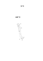
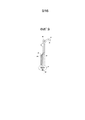
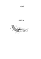
Фиг.1: Вид сбоку узла ларингеальной маски с тремя соединенными компонентами: жесткой трубкой (10), гибкой трубкой (20) и средством (30) визуального наблюдения. На этом виде эндотрахеальная трубка (40) помещена в свой направляющий канал (25).Figure 1: Side view of the site of the laryngeal mask with three connected components: a rigid tube (10), a flexible tube (20) and means (30) of visual observation. In this view, the endotracheal tube (40) is placed in its guide channel (25).
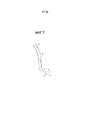
Фиг.2: Вид в перспективе узла ларингеальной маски с тремя соединенными компонентами: жесткой трубкой (10), гибкой трубкой (20) и средством (30) визуального наблюдения. На этом виде эндотрахеальная трубка (40) помещена в свой направляющий канал (25).Figure 2: A perspective view of a laryngeal mask assembly with three connected components: a rigid tube (10), a flexible tube (20), and visual observation means (30). In this view, the endotracheal tube (40) is placed in its guide channel (25).
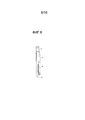
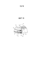
Фиг.3: Вид сбоку узла ларингеальной маски, когда жесткая трубка (10) прошла половину стадии отделения от гибкой трубки (20), где также имеется средство (30) визуального наблюдения, помещенное в один из его каналов. На этом виде эндотрахеальная трубка (40) помещена в свой направляющий канал (25).Figure 3: Side view of the site of the laryngeal mask, when the rigid tube (10) has passed half the stage of separation from the flexible tube (20), where there is also a means (30) of visual observation, placed in one of its channels. In this view, the endotracheal tube (40) is placed in its guide channel (25).
Фиг.4: Вид в перспективе узла ларингеальной маски, когда жесткая трубка (10) прошла половину стадии отделения от гибкой трубки (20), где также имеется средство (30) визуального наблюдения, помещенное в один из его каналов. На этом виде эндотрахеальная трубка (40) помещена в свой направляющий канал (25).Figure 4: A perspective view of the laryngeal mask assembly when the rigid tube (10) has passed half of the separation stage from the flexible tube (20), where there is also a visual observation means (30) placed in one of its channels. In this view, the endotracheal tube (40) is placed in its guide channel (25).
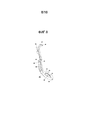
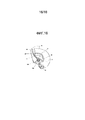
Фиг.5: Вид в перспективе жесткой трубки (10) с верхним жестким выступом (11) в форме язычка и дополнительным нижним жестким выступом (13) в форме язычка, где заканчиваются нижние направляющие рельсы (14). Также видна проксимальная область (15) узла, предназначенная для средства (30) визуального наблюдения.5: A perspective view of a rigid tube (10) with an upper rigid protrusion (11) in the form of a tongue and an additional lower rigid protrusion (13) in the form of a tongue, where the lower guide rails (14) end. Also visible is the proximal region (15) of the node, intended for means (30) of visual observation.
Фиг.6: Вид сзади жесткой трубки (10). Видны нижний жесткий выступ (13) в форме язычка и верхние жесткие рельсы (12), а также проксимальная область (15) узла, предназначенная для средства (30) визуального наблюдения.6: Rear view of the rigid tube (10). The lower rigid protrusion (13) in the form of a tongue and the upper rigid rails (12), as well as the proximal region (15) of the assembly, intended for visual observation means (30), are visible.
Фиг.7: Вид сбоку жесткой трубки (10) с верхним жестким выступом (11) в форме язычка и нижним жестким выступом (13) в форме язычка, при этом верхние направляющие рельсы (12) и нижние направляющие рельсы (14) также видны. Можно также видеть проксимальную область (15) узла, предназначенную для средства (30) визуального наблюдения.7: Side view of a rigid tube (10) with an upper rigid protrusion (11) in the form of a tongue and a lower hard protrusion (13) in the form of a tongue, while the upper guide rails (12) and lower guide rails (14) are also visible. You can also see the proximal region (15) of the node, intended for means (30) of visual observation.
Фиг.8: Вид в перспективе гибкой трубки (20), которая имеет проксимальный прямой участок, центральный искривленный участок, а также дистальное надувное кольцо или ненадувное гелевое кольцо (21). В представленном варианте осуществления показаны четыре возможных канала, при этом в различных вариантах осуществления каждый из них может присутствовать независимо от других:Fig. 8: A perspective view of a flexible tube (20) that has a proximal straight portion, a central curved portion, and also a distal inflatable ring or non-inflatable gel ring (21). In the presented embodiment, four possible channels are shown, while in various embodiments, each of them may be present independently of the others:
направляющий канал (25) для эндотрахеальной трубки (40), разделенный на две секции: одну продольно-открытую (25a) и другую (25b), которая не является таковой;a guide channel (25) for the endotracheal tube (40), divided into two sections: one longitudinally open (25a) and the other (25b), which is not one;
направляющий канал (26) для средства (30) визуального наблюдения; этот канал (26) имеет встроенную оптическую линзу, прикрепленную дистально к концу упомянутого канала;a guide channel (26) for the means (30) of visual observation; this channel (26) has an integrated optical lens attached distally to the end of said channel;
направляющий канал (27) для аспирации выделений с дистальной поверхности встроенной оптической линзы, прикрепленной дистально к направляющему каналу (26) для оптического средства; а такжеa guide channel (27) for aspirating the discharge from the distal surface of the integrated optical lens attached distally to the guide channel (26) for the optical means; as well as
направляющий канал (28) для аспирационного пищеводного зонда, который дистально заканчивается на выступе (22), являющемся зоной закрытия для сфинктера пищевода.a guide channel (28) for the aspiration esophageal probe, which distally ends at the protrusion (22), which is the closure zone for the esophagus sphincter.
Кроме того, в кольце (21) видна гибкая оболочка (23), присоединенная внутренней частью к проксимальной области кольца (21), которая накрывает жесткий выступ (11) в форме язычка, когда жесткая трубка (10) соединена с гибкой трубкой (20). Гибкая оболочка продолжается дистально с помощью двух удлиненных участков (24), которые дистально соединены с внутренней областью кольца (21).In addition, a flexible shell (23) is visible in the ring (21), attached internally to the proximal region of the ring (21), which covers the tongue-shaped rigid protrusion (11) when the rigid tube (10) is connected to the flexible tube (20) . The flexible membrane extends distally with the help of two elongated sections (24), which are distally connected to the inner region of the ring (21).
Фиг.9: Вид спереди гибкой трубки (20), имеющей проксимальный прямой участок, центральный искривленный участок, а также дистальное надувное кольцо или ненадувное гелевое кольцо (21). В представленном варианте осуществления показаны четыре возможных канала, при этом в различных вариантах осуществления каждый из них может присутствовать независимо от других:Fig. 9: Front view of a flexible tube (20) having a proximal straight portion, a central curved portion, and also a distal inflatable ring or non-inflatable gel ring (21). In the presented embodiment, four possible channels are shown, while in various embodiments, each of them may be present independently of the others:
направляющий канал (25) для эндотрахеальной трубки (40);a guide channel (25) for the endotracheal tube (40);
направляющий канал (26) для средства (30) визуального наблюдения; этот канал (26) имеет встроенную оптическую линзу, прикрепленную дистально к концу упомянутого канала;a guide channel (26) for the means (30) of visual observation; this channel (26) has an integrated optical lens attached distally to the end of said channel;
направляющий канал (27) для аспирации выделений с дистальной поверхности встроенной оптической линзы, прикрепленной дистально к направляющему каналу (26) для оптического средства; а такжеa guide channel (27) for aspirating the discharge from the distal surface of the integrated optical lens attached distally to the guide channel (26) for the optical means; as well as
направляющий канал (28) для аспирационного пищеводного зонда, дистально заканчивающийся на выступе (22), который может служить зоной закрытия для сфинктера пищевода.a guide channel (28) for the esophageal aspiration probe, distally ending at the protrusion (22), which can serve as a closure zone for the esophagus sphincter.
Фиг.10: Вид сверху гибкой трубки (20), имеющей проксимальный прямой участок, центральный искривленный участок, а также дистальное надувное кольцо или ненадувное гелевое кольцо (21). В представленном варианте осуществления показаны четыре возможных канала, при этом в различных вариантах осуществления каждый из них может присутствовать независимо от других:Figure 10: Top view of a flexible tube (20) having a proximal straight section, a central curved section, as well as a distal inflatable ring or non-inflatable gel ring (21). In the presented embodiment, four possible channels are shown, while in various embodiments, each of them may be present independently of the others:
направляющий канал (25) для эндотрахеальной трубки (40), разделенный на две секции: одну продольно-открытую (25a) и другую (25b), которая не является таковой;a guide channel (25) for the endotracheal tube (40), divided into two sections: one longitudinally open (25a) and the other (25b), which is not one;
направляющий канал (26) для средства (30) визуального наблюдения; этот канал (26) имеет встроенную оптическую линзу, прикрепленную дистально к концу упомянутого канала;a guide channel (26) for the means (30) of visual observation; this channel (26) has an integrated optical lens attached distally to the end of said channel;
направляющий канал (27) для аспирации выделений с дистальной поверхности встроенной оптической линзы, прикрепленной дистально к направляющему каналу (26) для оптического средства; а такжеa guide channel (27) for aspirating the discharge from the distal surface of the integrated optical lens attached distally to the guide channel (26) for the optical means; as well as
направляющий канал (28) для аспирационного пищеводного зонда, дистально заканчивающийся на выступе (22), который может служить зоной закрытия для сфинктера пищевода. a guide channel (28) for the esophageal aspiration probe, distally ending at the protrusion (22), which can serve as a closure zone for the esophagus sphincter.
Кроме того, в кольце (21) видна гибкая оболочка (23), присоединенная своей внутренней частью к проксимальной области кольца (21), которая накрывает жесткий выступ (11) в форме язычка, когда жесткая трубка (10) соединена с гибкой трубкой (20). Гибкая оболочка продолжается дистально с помощью двух удлиненных участков (24), которые дистально соединены с внутренней областью кольца (21). В кольце также видны несколько "толкателей" или выступов (29), служащих для направления эндотрахеальной трубки к центральной оси кольца (21), а также служащих для предотвращения смятия ларингеальной маски в вертикальном направлении.In addition, a flexible shell (23) is visible in the ring (21), attached with its inner part to the proximal region of the ring (21), which covers the tongue-shaped rigid protrusion (11) when the rigid tube (10) is connected to the flexible tube (20) ) The flexible membrane extends distally with the help of two elongated sections (24), which are distally connected to the inner region of the ring (21). Several “pushers” or protrusions (29) are also visible in the ring, which serve to direct the endotracheal tube to the central axis of the ring (21), as well as to prevent vertical collapse of the laryngeal mask.
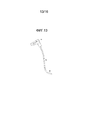
Фиг.11: Вид в перспективе гибкой трубки (20), где показано отделение (50), предназначенное для размещения батареек (51), питающих устройство в целом. Это отделение связано и соединено с проксимальной частью гибкой трубки (26) посредством соединительной области (53). Это отделение (50) также имеет соединительную область (52), соединяющую со средством (30) визуального наблюдения, предпочтительно полую, через которую проходит гибкая трубка (32) для средства (30) визуального наблюдения. Это отделение (50) имеет соединительную область (54), соединяющую с монитором (31), через которую передается электроэнергия, необходимая для устройства.11: A perspective view of a flexible tube (20), which shows the compartment (50), designed to accommodate batteries (51) that feed the device as a whole. This compartment is connected and connected to the proximal part of the flexible tube (26) through the connecting region (53). This compartment (50) also has a connecting region (52) connecting to the visual observation means (30), preferably a hollow, through which the flexible tube (32) for the visual observation means (30) passes. This compartment (50) has a connecting region (54) connecting to the monitor (31), through which the electric power needed for the device is transmitted.
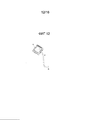
Фиг.12: Вид в перспективе средства (30) визуального наблюдения, которое в представленном варианте осуществления состоит из монитора (31), гибкой трубки (32), а также дистальной области (33) для размещения камеры, осветительных элементов и оптической линзы.12: A perspective view of the visual observation means (30), which in the present embodiment consists of a monitor (31), a flexible tube (32), as well as a distal region (33) for accommodating the camera, lighting elements and an optical lens.
Фиг.13: Вид сбоку средства (30) визуального наблюдения, которое в представленном варианте осуществления состоит из монитора (31), гибкой трубки (32) и дистальной трубчатой области (33) для размещения камеры, осветительных элементов и оптической линзы.13: A side view of the visual observation means (30), which in the present embodiment consists of a monitor (31), a flexible tube (32), and a distal tubular region (33) for receiving a camera, lighting elements, and an optical lens.
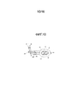
Фиг.14: Поперечное сечение конца узла ларингеальной маски, где в число видимых элементов входят жесткая трубка (10), гибкая трубка (20), передаточная трубка для средства (32) визуального наблюдения, дистальная область (33) гибкой трубки (32), где расположены оптические фокусирующие линзы (35), видеокамера (37), осветительное средство (38b), а также надувное кольцо (21).Fig: Cross section of the end of the node laryngeal mask, where the number of visible elements include a rigid tube (10), a flexible tube (20), a transfer tube for means (32) of visual observation, the distal region (33) of the flexible tube (32), where the optical focusing lenses (35), a video camera (37), a lighting device (38b), and an inflatable ring (21) are located.
Фиг.15: Расширенный участок фиг.14, где элементы, представленные на фиг.13, можно видеть подробнее: жесткая трубка (10), гибкая трубка (20), надувное кольцо (21), дистальная область (33) гибкой трубки (32), видеокамера (37), содержащая свои электронные элементы (34) в проксимальной области, оптические элементы (38a) в своей дистальной области (38), оптическая фокусирующая линза (35), соединенная с дистальной областью (33) гибкой трубки (32); эта оптическая фокусирующая линза также служит для создания герметичного дистального уплотнения (33) для гибкой трубки (32); оптическая фокусирующая линза (36), соединенная с дистальной областью гибкой трубки (26); эта оптическая фокусирующая линза (36) также служит для создания герметичного дистального уплотнения для гибкой трубки (26). Линза (36) имеет выступ (36a) для направления аспирации гибкой трубки (27) вниз.Fig. 15: An expanded section of Fig. 14, where the elements shown in Fig. 13 can be seen in more detail: a rigid tube (10), a flexible tube (20), an inflatable ring (21), a distal region (33) of a flexible tube (32 ), a video camera (37) containing its electronic elements (34) in the proximal region, optical elements (38a) in its distal region (38), an optical focusing lens (35) connected to the distal region (33) of the flexible tube (32) ; this optical focusing lens also serves to create a sealed distal seal (33) for the flexible tube (32); an optical focusing lens (36) connected to the distal region of the flexible tube (26); this optical focusing lens (36) also serves to create a tight distal seal for the flexible tube (26). The lens (36) has a protrusion (36a) to direct the aspiration of the flexible tube (27) down.
Фиг.16: Расширенный участок фиг.14, ориентированный в переднем направлении, где элементы, представленные на фиг.14, можно видеть подробнее: жесткая трубка (10), гибкая трубка (20), гибкая оболочка (23), окружающая жесткий выступ (11) в форме язычка, удлиненные участки (24) гибкой оболочки (23), надувное или гелевое кольцо (21), дистальная крышка (22) для закрытия сфинктера пищевода, которая может быть полой, так чтобы аспирационный зонд мог проходить насквозь в пищевод, направляющий канал (25) гибкой трубки (20), оптические элементы видеокамеры (38a), осветительная система (38b).Fig. 16: An expanded section of Fig. 14 oriented in the forward direction, where the elements shown in Fig. 14 can be seen in more detail: a rigid tube (10), a flexible tube (20), a flexible shell (23) surrounding a rigid protrusion ( 11) in the form of a tongue, elongated sections (24) of the flexible membrane (23), an inflatable or gel ring (21), a distal cap (22) to close the esophageal sphincter, which can be hollow, so that the aspiration probe can pass through the esophagus, guide channel (25) of flexible tube (20), optical elements of a video camera (38a), lighting YSTEM (38b).
ПОДРОБНОЕ ОПИСАНИЕ ИЗОБРЕТЕНИЯDETAILED DESCRIPTION OF THE INVENTION
Таким образом, в своем первом аспекте изобретение сфокусировано на ларингеальной маске, содержащей следующие элементы:Thus, in its first aspect, the invention is focused on a laryngeal mask containing the following elements:
первый элемент, представляющий собой полую жесткую трубку (10), по существу выполненную в форме буквы "J", которая имеет продольное отверстие по всей своей длине; а такжеthe first element, which is a hollow rigid tube (10), essentially made in the form of the letter "J", which has a longitudinal hole along its entire length; as well as
второй элемент, представляющий собой гибкую трубку (20), также по существу выполненную в форме буквы "J", предназначенную для размещения в продольном отверстии первого элемента (10) и отделяемую от этого элемента. Данная трубка заканчивается на своем дистальном конце надувным или гелевым гортанным кольцом (21).the second element, which is a flexible tube (20), also essentially made in the form of the letter "J", designed to be placed in the longitudinal hole of the first element (10) and separated from this element. This tube ends at its distal end with an inflatable or gel laryngeal ring (21).
В своем втором аспекте изобретение сфокусировано на способе интубации и/или вентиляции легких пациента с использованием маски согласно любому из предшествующих пунктов, отличающимся наличием этапов:In its second aspect, the invention is focused on a method for intubating and / or ventilating a patient’s lungs using a mask according to any one of the preceding paragraphs, characterized by the steps:
введения ларингеальной маски, состоящей из первого (10) и второго (20) элементов, соединенных так, что полученный узел является по существу жестким, в гортань пациента, а также направления ее в гортань пациента до занятия ею правильного положения; а такжеintroducing a laryngeal mask consisting of the first (10) and second (20) elements connected so that the resulting node is essentially rigid into the larynx of the patient, as well as directing it into the larynx of the patient until it occupies the correct position; as well as
когда врач сочтет нужным, разделения первого (10) и второго (20) элементов, извлечения первого жесткого элемента (10) и оставления второго гибкого элемента (20) в гортани пациента для вентиляции легких.when the doctor considers it necessary, separating the first (10) and second (20) elements, removing the first rigid element (10) and leaving the second flexible element (20) in the patient's larynx for ventilation.
Ларингеальная маска, представленная изобретением, ниже будет описана подробнее со ссылкой на сопроводительные фигуры.The laryngeal mask represented by the invention will be described in more detail below with reference to the accompanying figures.
ОСНОВНЫЕ ЭЛЕМЕНТЫ УСТРОЙСТВАBASIC ELEMENTS OF THE DEVICE
Ларингеальная маска по изобретению содержит следующие два основных элемента.The laryngeal mask according to the invention contains the following two main elements.
Первый элемент представляет собой жесткую трубку (10), по существу выполненную в форме буквы "J". Эта жесткая J-образная форма по существу состоит из начальной незначительно искривленной проксимальной секции, за которой следует вторая прямолинейная промежуточная секция, и заканчивается третьей искривленной дистальной секцией. Поскольку она воспроизводит анатомическое строение дыхательных путей пациента, данная форма способствует введению ларингеальной маски в дыхательные пути, а также ее размещению в них в правильном положении. Благодаря такой форме также нет необходимости в чрезмерном вытягивании шеи пациента для введения устройства. Эта жесткая трубка имеет продольное отверстие по всей своей длине, при этом данное отверстие предназначено для размещения второго элемента, который по существу представляет собой гибкую ларингеальную маску (20), имеющую в своем составе гибкую трубку (26), заканчивающуюся на своем дистальном конце надувным или гелевым кольцом (21). Данная гибкая трубка (26) второго элемента (20) также по существу имеет форму буквы "J". Она содержит прямолинейную гибкую проксимальную секцию и криволинейную гибкую дистальную секцию, образующую определенный угол с первой секцией, а также имеет на конце надувное или гелевое кольцо (21). Эта гибкая трубка (26) служит для направления гибкой трубки (32) со средством (30) визуального наблюдения, содержащим видеокамеру и систему оптических линз, в тех предпочтительных вариантах осуществления изобретения, в которых содержится такая система.The first element is a rigid tube (10), essentially made in the form of the letter "J". This rigid J-shape essentially consists of an initial slightly curved proximal section, followed by a second rectilinear intermediate section, and ends with a third curved distal section. Since it reproduces the anatomical structure of the patient's airways, this form promotes the introduction of the laryngeal mask into the airways, as well as its placement in them in the correct position. Due to this form, there is also no need to stretch the patient’s neck excessively to insert the device. This rigid tube has a longitudinal hole along its entire length, while this hole is designed to accommodate a second element, which is essentially a flexible laryngeal mask (20), comprising a flexible tube (26), ending at its distal end with an inflatable or gel ring (21). This flexible tube (26) of the second element (20) also essentially has the shape of the letter "J". It contains a rectilinear flexible proximal section and a curved flexible distal section forming a certain angle with the first section, and also has an inflatable or gel ring at the end (21). This flexible tube (26) serves to guide the flexible tube (32) with visual observation means (30) comprising a video camera and an optical lens system in those preferred embodiments of the invention which comprise such a system.
В качестве опции гибкая трубка (26) второго элемента (20) может также иметь прикрепленную вторую трубку (25), предпочтительно выполненную из того же материала, что и гибкая трубка. Она может быть короче по длине и также быть открытой продольно в своей проксимальной области (25a) и закрытой в своей дистальной области (25b), чтобы служить в качестве направляющего канала. Этот направляющий канал (25) предназначен для размещения эндотрахеальной трубки (40) и служит ее направляющей. Предпочтительно он имеет ровно такие размеры, которые требуются для размещения эндотрахеальной трубки диаметром 8,5 мм, что представляет собой размер, наиболее часто используемый для взрослых. Кроме того, в одном варианте осуществления этот направляющий канал (25) в качестве опции может быть оборудован на одной стенке проксимальной области (25a) удерживающей системой, такой как выступ (25c), чтобы не допустить латерального смещения стенки (25a) проксимальной части гибкой трубки (25), и, таким образом, позволить закрепить эндотрахеальную трубку (40), проходящую через внутреннее пространство канала (25). Данная система может принимать различные формы, одна из которых может представлять собой выступ или бугорок (25c), проходящий вдоль канавки в жесткой трубке (10).As an option, the flexible tube (26) of the second element (20) may also have an attached second tube (25), preferably made of the same material as the flexible tube. It may be shorter in length and also open longitudinally in its proximal region (25a) and closed in its distal region (25b) to serve as a guide channel. This guide channel (25) is designed to accommodate the endotracheal tube (40) and serves as its guide. Preferably, it has exactly the dimensions required to accommodate the endotracheal tube 8.5 mm in diameter, which is the size most commonly used for adults. In addition, in one embodiment, this guide channel (25) may optionally be equipped with a retention system such as a protrusion (25c) on one wall of the proximal region (25a) to prevent lateral displacement of the proximal wall (25a) of the flexible tube (25), and thus allow the endotracheal tube (40) to pass through the internal space of the canal (25). This system can take various forms, one of which can be a protrusion or tubercle (25c) extending along a groove in a rigid tube (10).
В предпочтительном варианте осуществления изобретения второй элемент (20) также оснащен системой для отделения тканей дыхательных путей и, таким образом, для поднятия надгортанника в соответствии с потребностями анестезии пациента в данный момент времени. Эта система для отделения тканей дыхательных путей и поднятия надгортанника в своем составе имеет полую, мягкую и гибкую оболочку (23), которая становится жесткой, когда жесткий выступ (11) в форме язычка, расположенный на дистальном конце жесткой трубки первого элемента, вводится в ее внутреннее пространство. В некоторых вариантах осуществления эта гибкая оболочка (23), в свою очередь, состоит из двух слоев гибкого материала, перекрывающихся с проксимальной частью внутреннего кольца (21) ларингеальной маски (20), дистально в направлении центра упомянутого внутреннего кольца (21). Эти два гибких слоя могут быть соединены по всему своему краю или быть открыты на своем наиболее дистальном конце на подобии клапана Геймлиха, при этом они также могут соединяться с внутренней частью гелевого кольца посредством удлиненных участков (24).In a preferred embodiment of the invention, the second element (20) is also equipped with a system for separating the tissues of the respiratory tract and, thus, for raising the epiglottis in accordance with the needs of the patient's anesthesia at a given time. This system for separating the tissues of the respiratory tract and raising the epiglottis in its composition has a hollow, soft and flexible membrane (23), which becomes stiff when a rigid protrusion (11) in the form of a tongue, located on the distal end of the rigid tube of the first element, is introduced into it inner space. In some embodiments, this flexible sheath (23), in turn, consists of two layers of flexible material overlapping with the proximal part of the inner ring (21) of the laryngeal mask (20), distally toward the center of said inner ring (21). These two flexible layers can be joined along their entire edge or can be opened at its most distal end, similar to the Heimlich valve, while they can also be connected to the inside of the gel ring via elongated sections (24).
Когда гибкая трубка (26) второго элемента (20) соединена с жесткой трубкой (10) первого элемента, дистальный конец (11) выступа в форме язычка жесткой трубки (10), который предпочтительно имеет форму утиного носа, введен внутрь двух гибких слоев гибкой оболочки (23) ларингеальной маски (20) от своей проксимальной части до дистальной части. Таким образом, получаемый комбинированный выступ в форме язычка переходит из гибкого состояния в жесткое состояние. Это целесообразно для разделения тканей дыхательных путей на всем пути его перемещения в направлении своего конечного надлежащего положения. Это также помогает не допустить загораживания этими тканями области, находящейся в зоне видимости оптического средства, а также способствует приподниманию надгортанника. Жесткость этой системы помогает активно разделить эти мягкие ткани, поскольку движения, придаваемые первому жесткому элементу снаружи, передаются во внутреннее пространство ларингеальной маски ее наиболее дистальному участку на жестком выступе в форме язычка, подобном утиному носу. Далее, после того как процесс анестезии получил свое развитие и жесткий первый элемент (10) извлекается из узла, выступ (11) в форме язычка жесткой трубки (10) по логике также извлекается между двумя гибкими слоями гибкой оболочки (23) ларингеальной маски (20), и оболочка (23), таким образом, восстанавливает свою гибкую форму. В этой гибкой форме оболочка (23) может лишь пассивно удерживать ткани за пределами области, находящейся в пределах видимости для оптического средства, но она не может содействовать активному разделению этих мягких тканей. Это связано с тем, что после извлечения жесткого выступа в форме язычка движения, сообщаемые снаружи ларингеальной маски, не доходят до гибкой оболочки (23) в силу мягкости материала гибкой трубки (26) второго элемента (20).When the flexible tube (26) of the second element (20) is connected to the rigid tube (10) of the first element, the distal end (11) of the tongue-shaped protrusion of the rigid tube (10), which preferably has the shape of a duck nose, is inserted inside two flexible layers of a flexible shell (23) a laryngeal mask (20) from its proximal portion to the distal portion. Thus, the resulting tab in the form of a tongue passes from a flexible state to a rigid state. It is advisable to separate the tissues of the respiratory tract along the entire path of its movement in the direction of its final proper position. It also helps to prevent the area located in the visibility range of the optical means from being blocked by these tissues, and also helps to raise the epiglottis. The stiffness of this system helps to actively separate these soft tissues, since the movements attached to the first rigid element from the outside are transmitted to the inner space of the laryngeal mask to its most distal portion on the hard protrusion in the shape of a tongue, similar to a duck nose. Further, after the process of anesthesia has been developed and the hard first element (10) is removed from the node, a protrusion (11) in the form of a tongue of a rigid tube (10) is also logically removed between two flexible layers of a flexible membrane (23) of the laryngeal mask (20 ), and the shell (23), thus, restores its flexible form. In this flexible form, the sheath (23) can only passively hold tissue outside the region within sight of the optical means, but it cannot facilitate the active separation of these soft tissues. This is due to the fact that after removing the rigid protrusion in the form of a tongue, the movements reported outside the laryngeal mask do not reach the flexible shell (23) due to the softness of the material of the flexible tube (26) of the second element (20).
В одном возможном варианте осуществления эти два гибких слоя гибкой оболочки (23) соединены с внутренней областью кольца (21). Это происходит посредством удлиненных участков (24), продолжающихся дистально от дистальной части этих гибких слоев в направлении дистальной части кольца (21) во внутреннем пространстве ларингеальной маски (20). Эти удлиненные участки способствуют предотвращению падения вниз этих двух гибких слоев гибкой оболочки (23) и создания помех техническому зрению средства визуального наблюдения, загораживая его поле обзора. Они также служат для пассивного предотвращения попадания мягких тканей дыхательных путей и надгортанника в раструб ларингеальной маски. Эти два удлиненных участка могут также иметь различные конфигурации, однако оптимальной является треугольная конфигурация. Это обеспечивает большее разделение дистально, не создавая помех спереди поля обзора оптического средства, а также позволяет эндотрахеальной трубке (40) проходить между ними.In one possible embodiment, these two flexible layers of flexible shell (23) are connected to the inner region of the ring (21). This occurs through elongated sections (24) extending distally from the distal part of these flexible layers towards the distal part of the ring (21) in the inner space of the laryngeal mask (20). These elongated sections help to prevent the fall of these two flexible layers of the flexible shell (23) and interfere with the technical vision of the visual observer by blocking its field of view. They also serve to passively prevent soft tissues of the respiratory tract and epiglottis from entering the socket of the laryngeal mask. These two elongated sections may also have different configurations, however, the triangular configuration is optimal. This provides greater distal separation without interfering with the front of the field of view of the optical means, and also allows the endotracheal tube (40) to pass between them.
Второй элемент (20) в качестве опции также может иметь выступ или стопор (22) на дистальном конце надувного или гелевого кольца (21), предназначенный для закупоривания сфинктера пищевода, чтобы не допустить выхода содержимого пищевода в дыхательные пути. Это важно, поскольку существует большой риск попадания содержимого пищевода в легкие путем вдыхания с последующим развитием пневмонии, что приводит к летальному исходу для 50% пациентов. Этот выступ (22) может быть полым для обеспечения прохода аспирационного зонда в пищевод.The second element (20) can also optionally have a protrusion or stopper (22) at the distal end of the inflatable or gel ring (21), designed to block the esophagus sphincter to prevent esophageal contents from entering the airways. This is important because there is a high risk of esophageal contents entering the lungs by inhalation and subsequent pneumonia, which can be fatal for 50% of patients. This protrusion (22) may be hollow to allow passage of the aspiration probe into the esophagus.
В еще одном варианте осуществления раструб ларингеальной маски оснащен, по меньшей мере, одним "толкателем" или выступом (29), расположенным внутри него, чтобы предотвратить вертикальное смятие ларингеальной маски, вызванное давлением мягкий ткани в дыхательных путях пациента. Благодаря своему ориентационному положению он может также позволить направлять эндотрахеальную трубку (40) к центральной части продольной оси устройства (20) ларингеальной маски, тем самым не допуская ее устремления в нежелательном направлении и позволяя ей проходить непосредственно по центру голосовых связок.In yet another embodiment, the socket of the laryngeal mask is equipped with at least one "pusher" or protrusion (29) located inside it to prevent vertical collapse of the laryngeal mask caused by pressure of soft tissue in the respiratory tract of the patient. Due to its orientation position, it can also allow you to direct the endotracheal tube (40) to the central part of the longitudinal axis of the device (20) of the laryngeal mask, thereby preventing its aspiration in an undesirable direction and allowing it to pass directly through the center of the vocal cords.
ОПТИЧЕСКОЕ СРЕДСТВО НАБЛЮДЕНИЯ И ПРОТИВОКОНДЕНСАТНАЯ СИСТЕМАOPTICAL SURVEILLANCE SYSTEM AND ANTI-CONDENSATE SYSTEM
В предпочтительных вариантах осуществления изобретения к этим двум основным элементам (10) и (20) добавлены некоторые средства оптического контроля. Они выполняют множество функций и имеют ряд преимуществ: позволяют сфокусировать изображение на соответствующем расстоянии от голосовых связок, позволяют совместить ось обзора с осью перемещения для эндотрахеальной трубки, при этом оптическая фокусирующая линза (35) расположена в дистальной области (33) гибкой трубки (32), что также позволяет герметично закрыть дистальную область (33) гибкой трубки (32). Другая оптическая фокусирующая линза (36) расположена в дистальной области гибкой трубки (26) и обеспечивает герметичное закрытие канала (26) гибкой трубки (20), где размещено средство (30) визуального наблюдения ларингеальной маски. Это позволяет сохранять его чистым и не соприкасаться с выделениями пациента, а также исключить необходимость в его повторной стерилизации после каждого применения, позволяя сразу же его использовать в следующий раз.In preferred embodiments, some of the optical controls are added to these two main elements (10) and (20). They perform many functions and have several advantages: they allow you to focus the image at an appropriate distance from the vocal cords, allow you to combine the viewing axis with the axis of movement for the endotracheal tube, while the optical focusing lens (35) is located in the distal region (33) of the flexible tube (32) , which also allows you to tightly close the distal region (33) of the flexible tube (32). Another optical focusing lens (36) is located in the distal region of the flexible tube (26) and provides a tight seal of the channel (26) of the flexible tube (20), where the means (30) for visual observation of the laryngeal mask are located. This allows you to keep it clean and not in contact with the patient’s secretions, as well as to eliminate the need for re-sterilization after each use, allowing you to use it immediately the next time.
В предпочтительном варианте осуществления изобретения в состав набора оптических средств наблюдения входят: оптическая линза (35), расположенная дистально (33) в гибкой трубке (32) средства (30) визуального наблюдения, встроенная оптическая линза (36), закрепленная дистально в канале (26) ларингеальной маски (20), в котором размещается средство (30) визуального наблюдения, видеокамера (37), монитор или экран (31) с кнопками меню, гибкая полая трубка (32), через которую проходят провода, волоконная оптика или любое другое средство передачи изображений от линзы на видеокамеру (37), а также осветительная система (38b), при этом все они работают совместно вместе с противоконденсатной системой.In a preferred embodiment of the invention, the optical observation kit includes: an optical lens (35) located distally (33) in a flexible tube (32) of the visual observation means (30), an integrated optical lens (36) mounted distally in the channel (26 ) a laryngeal mask (20), which contains the means (30) of visual observation, a video camera (37), a monitor or a screen (31) with menu buttons, a flexible hollow tube (32) through which wires, fiber optics or any other means image transfer from PS video camera (37) and lighting system (38b), all of which work together with anticondensation system.
Батарейки (51) для устройства, снабжающие энергией монитор или экран (31), систему (37) видеокамеры и осветительную систему (38b), расположены в отделении (50). Это отделение связано и соединено с проксимальной частью гибкой трубки (26) соединительной областью (53). Это отделение (50) также имеет соединительную область (52), соединяющую со средством (30) визуального наблюдения, которая является полой и через которую проходит гибкая трубка (32) для средства (30) визуального наблюдения. Отделение (50) также имеет соединительную область (54), соединяющую с монитором (31), через которую передается электроэнергия, необходимая для устройства.The batteries (51) for the device that power the monitor or screen (31), the camera system (37), and the lighting system (38b) are located in the compartment (50). This compartment is connected and connected to the proximal part of the flexible tube (26) by the connecting region (53). This compartment (50) also has a connecting region (52) connecting to the visual observation means (30), which is hollow and through which the flexible tube (32) for the visual observation means (30) passes. The compartment (50) also has a connecting region (54) connecting to the monitor (31), through which the electric power needed for the device is transmitted.
В одном варианте осуществления монитор или экран имеет ряд кнопок для управления меню и системой оптической записи со съемными SD-картами памяти и дополнительным соединением для выхода видеосигнала.In one embodiment, the monitor or screen has a number of buttons for controlling the menu and the optical recording system with removable SD memory cards and an additional connection for outputting a video signal.
Узел средства визуального наблюдения в качестве опции может передавать изображение на другую принимающую систему с помощью беспроводного средства, например инфракрасного излучения, технологии Bluetooth или Wi-Fi.The visual observer assembly can optionally transmit the image to another receiving system using a wireless means, such as infrared radiation, Bluetooth or Wi-Fi technology.
Набор оптических средств наблюдения получает электроэнергию от батареек (51), размещенных в отделении (50) и обеспечивающих питание монитора или экрана, системы видеокамеры и осветительной системы. Батарейки в отделении (50), снабжающие энергией систему видеокамеры и осветительную систему, вырабатывают достаточно тепла для нагрева оптической линзы (35), расположенной дистально (33) в гибкой трубке (32) со средством для передачи изображений, при этом данная линза (35) нагревает встроенную оптическую линзу (36), закрепленную дистально в канале (26) ларингеальной маски (20). Это предотвращает конденсацию, вызванную изменением температуры, которое происходит, когда устройство проходит из холодной среды в теплую среду с более высоким уровнем влажности, такую как в дыхательных путях пациента. При такой конфигурации ларингеальная маска в изобретении может быть определена как ларингеальная видеомаска с оптическим средством наблюдения и встроенными оптическими линзами.A set of optical surveillance tools receives electricity from batteries (51) located in the compartment (50) and providing power to a monitor or screen, a video camera system and a lighting system. The batteries in the compartment (50) supplying the video camera system and the lighting system generate enough heat to heat the optical lens (35) located distally (33) in the flexible tube (32) with means for transmitting images, while this lens (35) heats the built-in optical lens (36) fixed distally in the channel (26) of the laryngeal mask (20). This prevents condensation caused by a temperature change that occurs when the device passes from a cold environment to a warm environment with a higher level of humidity, such as in the patient’s airways. With this configuration, the laryngeal mask in the invention can be defined as a laryngeal video mask with an optical surveillance tool and integrated optical lenses.
Система (30) визуального наблюдения может присоединяться или отсоединяться от остальной части системы путем ее проведения через гибкий канал (26) второго элемента или гибкую ларингеальную маску (20). Кроме того, как упоминалось выше, дистальный участок этой гибкой трубки (26) содержит систему (36) оптических линз, которая способствует фокусировке видеокамеры (37) и которая также помогает совместить ось обзора видеокамеры (37) с осью скольжения и продвижения эндотрахеальной трубки (40). Она нагревается для образования части противоконденсатной системы.The visual observation system (30) can be connected or disconnected from the rest of the system by conducting it through the flexible channel (26) of the second element or the flexible laryngeal mask (20). In addition, as mentioned above, the distal portion of this flexible tube (26) contains an optical lens system (36) that facilitates focusing of the video camera (37) and which also helps to align the viewing axis of the video camera (37) with the axis of sliding and advancement of the endotracheal tube (40) ) It is heated to form part of the anti-condensation system.
В предпочтительных вариантах осуществления изобретения противоконденсатная система расположена в дистальной части (33) гибкой трубки (32), содержащей систему (35) оптических линз. Противоконденсатная система, встроенная в ларингеальную видеомаску (20) и осветительную систему (38b), функционирует путем использования контакта и пространственной близости для нагрева дистальной оптической линзы (35), расположенной на дистальном конце (33) гибкой трубки (32). Оптическая линза (36), расположенная дистально в канале (26), направляющем гибкую трубку (32), также будет нагреваться благодаря контакту и пространственной близости, повышая свою температуру до температуры человеческого тела и не допуская конденсации. Такая конденсация образуется вследствие различия между более холодной средой вне тела пациента и более теплой и влажной средой внутри дыхательных путей пациента.In preferred embodiments, the anti-condensation system is located in the distal portion (33) of the flexible tube (32) containing the optical lens system (35). The anti-condensation system integrated into the laryngeal video mask (20) and the lighting system (38b) functions by using contact and spatial proximity to heat the distal optical lens (35) located on the distal end (33) of the flexible tube (32). An optical lens (36) located distally in the channel (26) guiding the flexible tube (32) will also be heated due to contact and spatial proximity, increasing its temperature to the temperature of the human body and avoiding condensation. Such condensation results from the difference between the colder environment outside the patient’s body and the warmer and wetter environment inside the patient’s airways.
СИСТЕМА АСПИРАЦИИ ВЫДЕЛЕНИЙ ИЗ ПИЩЕВОДАEsophageal Discharge Aspiration System
В другом предпочтительном варианте осуществления изобретение также предполагает наличие дополнительного канала (28), закрытого по всей своей длине, но открытого на обоих концах, который предназначен для аспирации выделений из пищевода. Этот канал проходит по всей длине от дистальной части надувного или гелевого кольца (21) ларингеальной маски (20) до проксимального участка ларингеальной маски (20), где он может соединяться со стандартной хирургической аспирационной системой.In another preferred embodiment, the invention also involves the presence of an additional channel (28), closed along its entire length, but open at both ends, which is designed to aspirate secretions from the esophagus. This channel runs along the entire length from the distal part of the inflatable or gel ring (21) of the laryngeal mask (20) to the proximal portion of the laryngeal mask (20), where it can be connected to a standard surgical aspiration system.
АСПИРАЦИОННАЯ СИСТЕМА ДЛЯ ВЫДЕЛЕНИЙ НА ОПТИЧЕСКОЙ СИСТЕМЕ, ПРЕДНАЗНАЧЕННОЙ ДЛЯ СРЕДСТВА ВИЗУАЛЬНОГО НАБЛЮДЕНИЯASPIRATION SYSTEM FOR ISOLATIONS ON THE OPTICAL SYSTEM INTENDED FOR VISUAL OBSERVATION MEANS
В другом предпочтительном варианте осуществления изобретение также включает дополнительный канал (27), закрытый по всей своей длине, но открытый на своем дистальном конце, а также в качестве опции закрытый пробкой на своем проксимальном конце. Этот канал предназначен для аспирации выделений на дистальной поверхности оптической линзы (36), расположенной дистально в гибком канале (26) ларингеальной маски (20). Этот канал проходит по всему пути от дистальной части гибкого канала (26), который проводит гибкую трубку (32) в своем внутреннем пространстве, до уровня дистальной оптической линзы (36) в гибком канале (26), а затем до проксимальной части ларингеальной маски (20). В этой точке он может соединяться со стандартной хирургической аспирационной системой, позволяющей очистить оптические элементы, если линза загрязняется выделениями.In another preferred embodiment, the invention also includes an additional channel (27), closed along its entire length, but open at its distal end, and also optionally closed with a plug at its proximal end. This channel is intended for aspiration of secretions on the distal surface of the optical lens (36) located distally in the flexible channel (26) of the laryngeal mask (20). This channel extends all the way from the distal part of the flexible channel (26), which conducts the flexible tube (32) in its inner space, to the level of the distal optical lens (36) in the flexible channel (26), and then to the proximal part of the laryngeal mask ( twenty). At this point, it can be connected to a standard surgical suction system, which allows you to clean the optical elements if the lens is contaminated with secretions.
КАНАЛ ПОДАЧИ КИСЛОРОДАOXYGEN SUPPLY CHANNEL
В качестве опции ларингеальная маска в изобретении может иметь канал (25) или трубопровод для подачи кислорода, закрытый по всей своей длине, отдельный или совмещенный, как и в остальных ларингеальных масках, имеющихся на рынке, либо он также может не быть закрытым по всей своей длине, отдельным или совмещенным, и в этом случае иметь открытый канал (25a) или трубопровод по всей своей длине за исключением дистального конца (25b), где на коротком отрезке должен быть закрыт.As an option, the laryngeal mask in the invention may have a channel (25) or an oxygen supply pipe that is closed along its entire length, separate or combined, as in other laryngeal masks available on the market, or it may not be closed all over length, separate or combined, and in this case have an open channel (25a) or pipeline along its entire length except for the distal end (25b), where it should be closed in a short section.
В случае если отсутствует отдельный или совмещенный канал или трубопровод для подачи кислорода, но имеется канал или трубопровод, открытый по всей своей длине (25a) кроме дистального конца (25b), где короткий участок является закрытым, используется эндотрахеальная трубка (40). Это может быть стандартная эндотрахеальная трубка любого типа, изготавливаемая любой компанией-производителем эндотрахеальных трубок, где канал (25b) и эндотрахеальная трубка (40) используются для выполнения двух функций:If there is no separate or combined channel or conduit for oxygen supply, but there is a channel or conduit open along its entire length (25a) except for the distal end (25b), where the short section is closed, an endotracheal tube (40) is used. This can be a standard endotracheal tube of any type, manufactured by any manufacturer of endotracheal tubes, where the channel (25b) and endotracheal tube (40) are used to perform two functions:
во-первых, для подачи кислорода пациенту, когда это устройство используется в режиме вентиляции, где пневматическая манжета эндотрахеальной трубки (40) снята или отведена назад и со стратегической точки зрения расположена на уровне дистального конца короткого закрытого отрезка канала (25b) подачи кислорода, при этом, будучи надутой, эта манжета создает герметичное уплотнение относительно закрытого канала (25b), позволяя проводить вентиляцию легких пациента при положительном давлении и без утечек;firstly, to supply oxygen to the patient when this device is used in ventilation mode, where the pneumatic cuff of the endotracheal tube (40) is removed or retracted and, from a strategic point of view, is located at the distal end of the short closed segment of the oxygen supply channel (25b), when this being inflated, this cuff creates a tight seal relative to the closed channel (25b), allowing ventilation of the patient's lungs at positive pressure and without leaks;
вторая функция заключается в использовании канала (25a) или трубопровода, открытого по всей своей длине за исключением короткого отрезка на его дистальном конце (25b), для направления эндотрахеальной трубки через голосовые связки с целью интубации пациента, когда устройство используется в режиме интубации. Для выполнения этого маневра по интубации пневматическая манжета эндотрахеальной трубки (40) сначала должна быть сдута, чтобы продвинуть эндотрахеальную трубку в закрытый канал (25b).the second function is to use a channel (25a) or a conduit open along its entire length, except for a short length at its distal end (25b), to guide the endotracheal tube through the vocal cords to intubate the patient when the device is used in intubation mode. To perform this intubation maneuver, the pneumatic cuff of the endotracheal tube (40) must first be deflated to advance the endotracheal tube into the closed canal (25b).
ОДИН ВАРИАНТ ОСУЩЕСТВЛЕНИЯ ИЗОБРЕТЕНИЯONE OPTION FOR CARRYING OUT THE INVENTION
Таким образом, согласно одному варианту осуществления изобретения гибкая часть (20) ларингеальной маски устройства имеет четыре канала:Thus, according to one embodiment of the invention, the flexible part (20) of the laryngeal mask of the device has four channels:
первый канал (28), который полностью закрыт по всей своей длине, но открыт на своих двух концах для аспирации выделений из пищевода,the first channel (28), which is completely closed along its entire length, but open at its two ends for aspiration of secretions from the esophagus,
второй канал (27), полностью закрытый по всей своей длине, но открытый на своем дистальном конце, а также закрытый на своем проксимальном конце крышкой, которая может открываться только в случае необходимости проведения аспирации выделений с дистальной поверхности оптической линзы (36) ларингеальной маски,the second channel (27), completely closed along its entire length, but open at its distal end, and also closed at its proximal end by a lid that can be opened only if it is necessary to aspirate the discharge from the distal surface of the optical lens (36) of the laryngeal mask,
третий канал (26), полностью закрытый по всей своей длине, при этом открытый только на своей проксимальной части, где вводится средство визуального наблюдения (32), и закрытый на своем дистальном участке оптической линзой (36) ларингеальной маски, а такжеthe third channel (26), completely closed along its entire length, while being open only at its proximal part, where visual observation means (32) are introduced, and closed at its distal section with an optical lens (36) of the laryngeal mask, and
четвертый канал (25), открытый практически по всей своей длине (25a) за исключением конечного дистального участка, который закрыт (25b), а также открытый на обоих своих концах, служащий для направления стандартной эндотрахеальной трубки (40).the fourth channel (25), open almost along its entire length (25a) except for the final distal section, which is closed (25b), and also open at both its ends, which serves to guide the standard endotracheal tube (40).
В предпочтительном варианте осуществления изобретения предусмотрена жесткая часть (10), имеющая жесткий выступ (11) в форме язычка на своей дистальной части.In a preferred embodiment of the invention, a rigid part (10) is provided having a rigid protrusion (11) in the form of a tongue on its distal part.
В предпочтительном варианте осуществления изобретения имеется специальное средство (30) оптического контроля с встроенной противоконденсатной системой.In a preferred embodiment of the invention, there is a special means (30) of optical control with an integrated anti-condensation system.
Данный предпочтительный вариант осуществления изобретения позволяет использовать стандартные эндотрахеальные трубки (40) вместо специальных силиконовых эндотрахеальных трубок, применяемых в других изделиях современного уровня техники, а также позволяет использовать трубки, внутренний диаметр которых достигает размера 8,5 мм, который чаще всего используется в анестезии для обычных взрослых людей.This preferred embodiment of the invention allows the use of standard endotracheal tubes (40) instead of special silicone endotracheal tubes used in other products of the state of the art, and also allows the use of tubes with an inner diameter of 8.5 mm, which is most often used in anesthesia for ordinary adults.
В одном варианте осуществления изобретения скольжение между жесткими элементами (10) ларингеальной маски и гибкими элементами (20) для отделения или отсоединения либо последующего соединения (если потребуется) двух элементов обеспечивается с помощью рельсов, проходящих по всей длине средней линии верхней части (12) и нижней части (14) жесткого элемента, а также с помощью канавок того же размера, расположенных вдоль средней линии гибкого элемента (20) ларингеальной маски.In one embodiment of the invention, the sliding between the rigid elements (10) of the laryngeal mask and the flexible elements (20) to separate or detach or subsequently connect (if necessary) the two elements is provided by rails running along the entire length of the midline of the upper part (12) and the lower part (14) of the rigid element, as well as using grooves of the same size located along the midline of the flexible element (20) of the laryngeal mask.
В одном варианте осуществления изобретения жесткий выступ (11) в форме язычка, расположенный в дистальной части первого элемента (10) устройства, выполняет функцию разделения мягких тканей дыхательных путей, а также функцию приподнимания надгортанника. На него также возложена функция предотвращения горизонтального смятия и закрытия кольца (21) ларингеальной маски, которое происходит в дыхательных путях пациента, когда мягкие ткани дыхательных путей смыкаются над кольцом (21) ларингеальной маски (20).In one embodiment of the invention, a rigid protrusion (11) in the form of a tongue, located in the distal part of the first element (10) of the device, performs the function of separating the soft tissues of the respiratory tract, as well as the function of lifting the epiglottis. It also has the function of preventing horizontal collapse and closing of the ring (21) of the laryngeal mask, which occurs in the respiratory tract of the patient when the soft tissues of the respiratory tract close above the ring (21) of the laryngeal mask (20).
В данном варианте осуществления изобретения режим подачи кислорода пациенту обоюдно сменяется между режимом вентиляции с использованием надувного или гелевого кольца и режимом интубации с использованием эндотрахеальной трубки, чтобы предоставить пациенту более высокое положительное давление и не допустить продолжительного оказания давления в той же области на мягкие ткани дыхательных путей.In this embodiment, the patient’s oxygen supply regimen is mutually changed between the ventilation mode using an inflatable or gel ring and the endotracheal tube intubation mode to provide the patient with a higher positive pressure and to prevent prolonged pressure in the same area on the soft tissues of the respiratory tract .
ПРОЦЕДУРА ВЕНТИЛЯЦИИ ЛЕГКИХ С ИСПОЛЬЗОВАНИЕМ УСТРОЙСТВА В ПРЕДПОЧТИТЕЛЬНОМ ВАРИАНТЕ ОСУЩЕСТВЛЕНИЯLUNG VENTILATION PROCEDURE USING THE DEVICE IN A PREFERRED EMBODIMENT
До введения устройства в дыхательные пути пациента стандартная эндотрахеальная трубка (40) извлекается или отводится назад в определенное положение в четвертом направляющем канале (25) в гибкой ларингеальной маске, так чтобы ее пневматическая манжета располагалась точно в закрытой дистальной части направляющего канала (25b). Эта манжета будет надута, так чтобы создать герметичное уплотнение относительно закрытой части четвертого направляющего канала (25b), при этом через ее внутреннее пространство затем будет поступать кислород для пациента.Before the device is inserted into the patient’s airways, the standard endotracheal tube (40) is removed or retracted to a certain position in the fourth guide channel (25) in the flexible laryngeal mask so that its pneumatic cuff is located exactly in the closed distal part of the guide channel (25b). This cuff will be inflated, so as to create a tight seal relative to the closed part of the fourth guide channel (25b), while oxygen for the patient will then flow through its interior.
Затем устройство вводится в дыхательные пути пациента, используя изображение, предоставляемое оптической системой (30) визуального наблюдения, при этом второй гибкий элемент (20) подсоединен в продольной канавке в первом жестком элементе (10), при этом средство (30) визуального наблюдения введено в третий канал (26) гибкой маски (20), при этом стандартная эндотрахеальная трубка (40) введена в четвертый направляющий канал (25), при этом ее манжета надута для создания герметичного уплотнения относительно закрытого канала (25b).Then, the device is inserted into the patient’s respiratory tract using the image provided by the optical system (30) for visual observation, while the second flexible element (20) is connected in the longitudinal groove in the first rigid element (10), while the means (30) of visual observation are introduced into the third channel (26) of the flexible mask (20), while the standard endotracheal tube (40) is inserted into the fourth guide channel (25), while its cuff is inflated to create a tight seal relative to the closed channel (25b).
После того как устройство введено в дыхательные пути пациента и заняло свое оптимальное положение под непосредственным наблюдением, обеспечиваемым средством (30) визуального наблюдения, дистальное надувное кольцо ларингеальной маски надувается, если используется модель надувного кольца. Если используется модель гелевого кольца, кольцо надувать не требуется.After the device is inserted into the respiratory tract of the patient and takes its optimal position under direct observation provided by means of visual observation (30), the distal inflatable ring of the laryngeal mask is inflated if the model of the inflatable ring is used. If a gel ring model is used, it is not necessary to inflate the ring.
Кислород подается проксимальной частью эндотрахеальной трубки (40) и поступает пациенту при работе этого устройства в режиме вентиляции.Oxygen is supplied by the proximal part of the endotracheal tube (40) and enters the patient during operation of this device in ventilation mode.
Если пациенту проводится оксигенация в контролируемом и стабильном режиме, жесткий элемент (10) может быть отсоединен и извлечен путем скольжения по рельсам (12) и (14) вдоль канавок в ларингеальной маске (20), при этом внутри дыхательных путей пациента остается только гибкая часть (20), а также эндотрахеальная трубка в качестве соединительного звена для переноса кислорода. Это не допускает создания давления на мягкие ткани и причинения травм пациенту.If the patient undergoes oxygenation in a controlled and stable mode, the rigid element (10) can be disconnected and removed by sliding along the rails (12) and (14) along the grooves in the laryngeal mask (20), while only the flexible part remains inside the patient’s airways (20) as well as an endotracheal tube as a connecting link for oxygen transfer. This prevents the creation of pressure on the soft tissues and causing injury to the patient.
В данном случает элементы (30) для визуального наблюдения могут быть извлечены или оставаться в своем канале (26).In this case, the elements (30) for visual observation can be removed or remain in their channel (26).
ПРОЦЕДУРА ИНТУБАЦИИ С ИСПОЛЬЗОВАНИЕМ УСТРОЙСТВА В ПРЕДПОЧТИТЕЛЬНОМ ВАРИАНТЕ ОСУЩЕСТВЛЕНИЯ ИЗОБРЕТЕНИЯINTUBATION PROCEDURE USING THE DEVICE IN A PREFERRED EMBODIMENT OF THE INVENTION
Когда врачу требуется провести интубацию, эта процедура начинается с режима вентиляции. Когда пациенту проводится стабильная оксигенация в режиме вентиляции, пневматическая манжета или шарик в эндотрахеальной трубке (40) сдувается, и она продвигается в направлении голосовых связок, пока не войдет в трахею, при этом в течение всего маневра осуществляется визуальное наблюдение. В этом месте пневматическая манжета или шарик в эндотрахеальной трубке (40) надувается повторно в упор с тканями трахеи, создавая герметичное уплотнение. После этого возобновляется подача кислорода пациенту, теперь прошедшему интубацию. В этот момент времени надувное кольцо (21) в ларингеальной маске (20) может быть сдуто.When a doctor needs to be intubated, this procedure begins with a ventilation regimen. When the patient undergoes stable oxygenation in ventilation mode, the pneumatic cuff or ball in the endotracheal tube (40) is deflated, and it moves in the direction of the vocal cords until it enters the trachea, while visual observation is performed throughout the maneuver. At this point, the pneumatic cuff or ball in the endotracheal tube (40) is inflated repeatedly against the end with tracheal tissues, creating a tight seal. After that, the supply of oxygen to the patient, now past the intubation, is resumed. At this point in time, the inflatable ring (21) in the laryngeal mask (20) may be deflated.
Теперь, когда пациент находится в стабильном состоянии, жесткий элемент (10) может быть отсоединен и извлечен путем скольжения по рельсам (12) и (14) вдоль канавок в ларингеальной маске (20), при этом сдутая гибкая маска (20) и эндотрахеальная трубка (40) могут оставаться для передачи кислорода пациенту.Now that the patient is in a stable state, the rigid element (10) can be detached and removed by sliding along the rails (12) and (14) along the grooves in the laryngeal mask (20), with the deflated flexible mask (20) and the endotracheal tube (40) may remain to transfer oxygen to the patient.
Гибкий элемент (20) также может быть извлечен, оставляя внутри пациента только эндотрахеальную трубку (40). Для достижения этого гибкий элемент (20) совершает скольжение в направлении изо рта наружу, при этом с помощью пальца поддерживается положение эндотрахеальной трубки (40) во рту и предотвращается ее выход наружу. Поскольку канал (25a) открыт, врач пальцем может сохранять положение трубки (40), пока кольцо (21) не выйдет наружу изо рта и трубку (40) можно будет захватить на другом конце кольца (21). Закрытый канал (25b) имеет малую длину, и его размеры точно подобраны так, чтобы позволить совершить данный маневр по извлечению гибкой маски (20), оставляя в дыхательных путях пациента только трубку (40). Трубка, во-первых, удерживается на месте стенкой канала (25b), а во-вторых, удерживается на месте стенкой кольца (21).The flexible member (20) can also be removed, leaving only the endotracheal tube (40) inside the patient. To achieve this, the flexible element (20) glides in the direction from the mouth to the outside, while with the help of a finger the position of the endotracheal tube (40) is maintained in the mouth and its exit is prevented. Since the channel (25a) is open, the doctor can use a finger to maintain the position of the tube (40) until the ring (21) comes out of the mouth and the tube (40) can be grasped at the other end of the ring (21). The closed channel (25b) has a small length, and its dimensions are precisely selected so as to allow this maneuver to remove the flexible mask (20), leaving only the tube (40) in the patient’s airways. The tube is, firstly, held in place by the wall of the channel (25b), and secondly, held in place by the wall of the ring (21).
Claims (24)
Applications Claiming Priority (1)
| Application Number | Priority Date | Filing Date | Title |
|---|---|---|---|
| PCT/ES2013/070138 WO2014135715A1 (en) | 2013-03-06 | 2013-03-06 | Laryngeal mask with retractable rigid tab and means for ventilation and intubation |
Publications (2)
| Publication Number | Publication Date |
|---|---|
| RU2015142256A RU2015142256A (en) | 2017-04-10 |
| RU2626902C2 true RU2626902C2 (en) | 2017-08-02 |
Family
ID=51490658
Family Applications (1)
| Application Number | Title | Priority Date | Filing Date |
|---|---|---|---|
| RU2015142256A RU2626902C2 (en) | 2013-03-06 | 2013-03-06 | Laryngeal videomask with rigid retracting tab and tool for ventilation and intubation |
Country Status (12)
| Country | Link |
|---|---|
| US (1) | US10188815B2 (en) |
| EP (1) | EP2965687B1 (en) |
| JP (1) | JP6272363B2 (en) |
| CN (1) | CN105050481B (en) |
| AU (1) | AU2013380597B2 (en) |
| BR (1) | BR112015020842A2 (en) |
| CA (1) | CA2899845C (en) |
| ES (1) | ES2668026T3 (en) |
| HK (1) | HK1216493A1 (en) |
| MX (1) | MX363344B (en) |
| RU (1) | RU2626902C2 (en) |
| WO (1) | WO2014135715A1 (en) |
Families Citing this family (18)
| Publication number | Priority date | Publication date | Assignee | Title |
|---|---|---|---|---|
| US10149955B2 (en) | 2013-06-20 | 2018-12-11 | Ambu A/S | Laryngeal mask |
| CN105377347B (en) * | 2013-06-20 | 2017-07-04 | 安布股份有限公司 | Laryngeal mask |
| SG2014011720A (en) | 2014-02-10 | 2015-09-29 | Craig Wight Ronald | An airway management device and method of manufacture |
| CA158881S (en) * | 2014-03-28 | 2015-05-04 | Teleflex Life Sciences | Laryngeal mask |
| AU356603S (en) * | 2014-03-28 | 2014-07-28 | Teleflex Life Sciences | Medical equipment |
| FR3056407B1 (en) * | 2016-09-27 | 2018-11-30 | Deltamedics | LARYNGE DEVICE COMPRISING A SLITTED TUBE AND A DISPLAY SCREEN |
| FR3056406B1 (en) * | 2016-09-27 | 2018-11-30 | Deltamedics | LARYNGE DEVICE COMPRISING A TUBE WITH A SIDE SLOT |
| AU201714823S (en) | 2017-02-27 | 2017-10-12 | Teleflex Life Sciences Unlimited Co | Laryngeal mask airway device |
| CN107233646A (en) * | 2017-05-26 | 2017-10-10 | 世耀生技股份有限公司 | Endotracheal tube laryngeal mask fixture |
| US10213567B1 (en) | 2017-11-08 | 2019-02-26 | Shan Theventhiran | Easily removable intubating LMA |
| WO2019155481A1 (en) * | 2018-02-07 | 2019-08-15 | Ananthanarayanan Kalyanaraman | Supraglottic airway device with a dynamic cuff with superior ventilating capability |
| US10653307B2 (en) | 2018-10-10 | 2020-05-19 | Wm & Dg, Inc. | Medical devices for airway management and methods of placement |
| ES2753928A1 (en) * | 2018-10-10 | 2020-04-14 | Servicio Gallego De Salud Sergas | PATIENT INTUBATION DEVICE BY AIR (Machine-translation by Google Translate, not legally binding) |
| CN109621128A (en) * | 2019-01-18 | 2019-04-16 | 浙江简成医疗科技有限公司 | A kind of distensible endoscope diagnosis laryngeal mask |
| CN111514419B (en) * | 2019-02-02 | 2023-08-04 | 李大庆 | Far-end subassembly and have its laryngeal mask main part, laryngeal mask are held to video |
| EP3909630A4 (en) * | 2019-02-02 | 2023-02-22 | Changsha Magill Medical Technology Co., Ltd. | Laryngeal mask airway |
| AR118974A1 (en) * | 2020-05-21 | 2021-11-17 | Raxte S A | LARYNGEOTRACHEAL INTUBATED DEVICE AND INTUBATION PROCEDURES |
| GB2611046B (en) * | 2021-09-23 | 2023-10-25 | Willmott Orthopaedics Ltd | Laryngeal mask airway |
Citations (6)
| Publication number | Priority date | Publication date | Assignee | Title |
|---|---|---|---|---|
| US20020189618A1 (en) * | 1996-10-16 | 2002-12-19 | Augustine Scott Douglas | Airway device with provision for coupling to an introducer |
| US20060004260A1 (en) * | 1999-10-14 | 2006-01-05 | Ben Boedeker | Endotracheal video device |
| US20060180155A1 (en) * | 2005-01-26 | 2006-08-17 | Ezc Holding, Llc | Video-assisted laryngeal mask airway devices |
| US20080276932A1 (en) * | 2005-11-03 | 2008-11-13 | Bruno Bassoul | Laryngeal Mask Adapted For the Introduction and Removal of an Intubation Probe |
| WO2011041684A2 (en) * | 2009-10-02 | 2011-04-07 | Medtronic-Xomed, Inc. | Endotracheal tube apparatus |
| US20110144436A1 (en) * | 2009-12-11 | 2011-06-16 | University Hospitals Of Cleveland | Airway management |
Family Cites Families (36)
| Publication number | Priority date | Publication date | Assignee | Title |
|---|---|---|---|---|
| US5287484A (en) * | 1989-06-21 | 1994-02-15 | Hitachi, Ltd. | Multi-processor system for invalidating hierarchical cache |
| JPH0799176B2 (en) | 1989-07-17 | 1995-10-25 | エヌティエヌ株式会社 | Constant velocity universal joint |
| US5174283A (en) * | 1989-11-08 | 1992-12-29 | Parker Jeffrey D | Blind orolaryngeal and oroesophageal guiding and aiming device |
| GB9102821D0 (en) | 1991-02-11 | 1991-03-27 | Brain Archibald Ian Jeremy | An intubating laryngeal mask airway |
| US5529582A (en) * | 1994-02-01 | 1996-06-25 | Fukuhara; Tomio | Apparatus for inserting laryngeal mask |
| US5551946A (en) * | 1994-05-17 | 1996-09-03 | Bullard; James R. | Multifunctional intubating guide stylet and laryngoscope |
| US6634354B2 (en) | 1996-02-26 | 2003-10-21 | Evergreen Medical Incorporated | Laryngeal mask airway |
| US6568388B2 (en) | 1996-02-26 | 2003-05-27 | Evergreen Medical Incorporated | Method and apparatus for ventilation / oxygenation during guided insertion of an endotracheal tube |
| US5623921A (en) | 1996-04-10 | 1997-04-29 | Kinsinger; J. William | Laryngeal mask airway and method for its use |
| US5682880A (en) | 1996-07-26 | 1997-11-04 | Brain; Archibald Ian Jeremy | Laryngeal-mask airway with guide element, stiffener, and fiberoptic access |
| US6070581A (en) * | 1996-10-16 | 2000-06-06 | Augustine Medical, Inc. | Laryngeal airway device |
| US5937860A (en) | 1997-04-10 | 1999-08-17 | Cook; Daniel J. | Laryngeal mask |
| US6354993B1 (en) * | 1999-06-21 | 2002-03-12 | Karl Storz Gmbh & Co. Kg | Rigid intubating laryngoscope with interchangeable blade and video display |
| US7159589B2 (en) * | 2001-08-23 | 2007-01-09 | Indian Ocean Medical Inc. | Disposable laryngeal mask airway device |
| US7040322B2 (en) | 2001-11-08 | 2006-05-09 | Fortuna Anibal De Oliveira | Combination artificial airway device and esophageal obturator |
| US6705322B2 (en) | 2002-03-11 | 2004-03-16 | Ti-Li Chang | Laryngeal mask airway |
| US7182728B2 (en) * | 2002-07-24 | 2007-02-27 | Intubation Plus, Inc. | Laryngoscope with multi-directional eyepiece |
| ES2234387B1 (en) * | 2003-02-24 | 2007-08-01 | Pedro Acha Gandarias | OPTICAL LIGHTING LINGING SCOPE WITH INCORPORATED FLUID EXTRACTION DEVICE. |
| US7128071B2 (en) * | 2003-09-10 | 2006-10-31 | Indian Ocean Medical Inc. | Intubating laryngeal mask airway device with fiber optic assembly |
| US7946981B1 (en) | 2003-10-23 | 2011-05-24 | Anthony Cubb | Two-piece video laryngoscope |
| TWM262190U (en) * | 2004-08-09 | 2005-04-21 | Future Top Medical Environment | Structure of throat cover |
| US8863746B2 (en) * | 2005-07-25 | 2014-10-21 | Kim Technology Partners, LP | Device and method for placing within a patient an enteral tube after endotracheal intubation |
| JP4761928B2 (en) * | 2005-10-24 | 2011-08-31 | Hoya株式会社 | Intubation support device |
| MX2008009437A (en) * | 2006-01-24 | 2009-06-22 | Page 65 Sl | Luminous optical laryngoscope. |
| US7938118B2 (en) | 2006-04-06 | 2011-05-10 | Kessler Joel D | Combination laryngeal mask airway with dual blocking and fluid removal features and method |
| EP1938855A1 (en) | 2006-12-29 | 2008-07-02 | Ti-Li Chang | Laryngeal mask airway without inflating |
| TW200932296A (en) * | 2008-01-31 | 2009-08-01 | Tien-Sheng Chen | Clip device and laryngeal mask airway |
| NZ597652A (en) * | 2009-07-06 | 2014-02-28 | Umedaes Ltd | Artificial airway |
| CA2781059A1 (en) * | 2009-11-16 | 2011-05-19 | Verathon Inc. | Channel laryngoscopes and systems |
| US8202215B2 (en) | 2010-02-11 | 2012-06-19 | Plastics Industry Development Center | Pharyngeal intubation guiding device |
| US20120024285A1 (en) * | 2010-08-02 | 2012-02-02 | Dashawetz Roman W | Laryngeal mask airway placement system and method |
| US8220461B1 (en) * | 2011-02-01 | 2012-07-17 | Guerra Phillip B | Oral airway |
| WO2012164868A1 (en) * | 2011-05-31 | 2012-12-06 | 国立大学法人岡山大学 | Laryngeal mask |
| CN202236730U (en) * | 2011-09-02 | 2012-05-30 | 肖哲毅 | Device for realizing visual implantation and post-implantation checking of laryngeal mask |
| TW201311305A (en) * | 2011-09-09 | 2013-03-16 | Tien-Sheng Chen | Tracheal intubation device |
| US20150165148A1 (en) * | 2013-11-07 | 2015-06-18 | Catherine Susan Kozlowski | Endotracheal Tube Insertion Device |
-
2013
- 2013-03-06 RU RU2015142256A patent/RU2626902C2/en not_active IP Right Cessation
- 2013-03-06 ES ES13877022.7T patent/ES2668026T3/en active Active
- 2013-03-06 AU AU2013380597A patent/AU2013380597B2/en not_active Ceased
- 2013-03-06 JP JP2015560731A patent/JP6272363B2/en not_active Expired - Fee Related
- 2013-03-06 WO PCT/ES2013/070138 patent/WO2014135715A1/en active Application Filing
- 2013-03-06 US US14/772,850 patent/US10188815B2/en active Active
- 2013-03-06 CA CA2899845A patent/CA2899845C/en not_active Expired - Fee Related
- 2013-03-06 EP EP13877022.7A patent/EP2965687B1/en active Active
- 2013-03-06 BR BR112015020842A patent/BR112015020842A2/en not_active Application Discontinuation
- 2013-03-06 MX MX2015011127A patent/MX363344B/en unknown
- 2013-03-06 CN CN201380074320.5A patent/CN105050481B/en not_active Expired - Fee Related
-
2016
- 2016-04-12 HK HK16104162.6A patent/HK1216493A1/en not_active IP Right Cessation
Patent Citations (6)
| Publication number | Priority date | Publication date | Assignee | Title |
|---|---|---|---|---|
| US20020189618A1 (en) * | 1996-10-16 | 2002-12-19 | Augustine Scott Douglas | Airway device with provision for coupling to an introducer |
| US20060004260A1 (en) * | 1999-10-14 | 2006-01-05 | Ben Boedeker | Endotracheal video device |
| US20060180155A1 (en) * | 2005-01-26 | 2006-08-17 | Ezc Holding, Llc | Video-assisted laryngeal mask airway devices |
| US20080276932A1 (en) * | 2005-11-03 | 2008-11-13 | Bruno Bassoul | Laryngeal Mask Adapted For the Introduction and Removal of an Intubation Probe |
| WO2011041684A2 (en) * | 2009-10-02 | 2011-04-07 | Medtronic-Xomed, Inc. | Endotracheal tube apparatus |
| US20110144436A1 (en) * | 2009-12-11 | 2011-06-16 | University Hospitals Of Cleveland | Airway management |
Also Published As
| Publication number | Publication date |
|---|---|
| AU2013380597A1 (en) | 2015-09-24 |
| CA2899845A1 (en) | 2014-09-12 |
| US10188815B2 (en) | 2019-01-29 |
| EP2965687A4 (en) | 2016-11-30 |
| WO2014135715A1 (en) | 2014-09-12 |
| MX2015011127A (en) | 2016-03-11 |
| EP2965687B1 (en) | 2018-01-31 |
| US20160008562A1 (en) | 2016-01-14 |
| EP2965687A1 (en) | 2016-01-13 |
| BR112015020842A2 (en) | 2017-07-18 |
| CN105050481A (en) | 2015-11-11 |
| CN105050481B (en) | 2017-07-21 |
| AU2013380597B2 (en) | 2018-06-14 |
| MX363344B (en) | 2019-03-20 |
| CA2899845C (en) | 2019-06-25 |
| RU2015142256A (en) | 2017-04-10 |
| JP2016516455A (en) | 2016-06-09 |
| ES2668026T3 (en) | 2018-05-16 |
| JP6272363B2 (en) | 2018-01-31 |
| HK1216493A1 (en) | 2016-11-18 |
Similar Documents
| Publication | Publication Date | Title |
|---|---|---|
| RU2626902C2 (en) | Laryngeal videomask with rigid retracting tab and tool for ventilation and intubation | |
| US11202561B2 (en) | Medical devices and methods of placement | |
| CA2957220C (en) | Medical devices and methods of placement | |
| US11147442B2 (en) | Medical devices and methods of placement | |
| US10335023B2 (en) | Endotracheal tube insertion device | |
| AU691299B2 (en) | A fibreoptic intubating laryngeal mask airway | |
| JP6525481B2 (en) | Medical device and method of using the medical device | |
| US20100010307A1 (en) | Intubation tube | |
| CN107427196B (en) | Endotracheal tube insertion device | |
| JP2013510699A (en) | Channel laryngoscope and system | |
| WO2017205357A1 (en) | Medical devices and methods of placement | |
| EP3986243A1 (en) | Shielded intubation guide and method |
Legal Events
| Date | Code | Title | Description |
|---|---|---|---|
| MM4A | The patent is invalid due to non-payment of fees |
Effective date: 20200307 |