RU26257U1 - VALVE REGULATING MICROFLOW - Google Patents
VALVE REGULATING MICROFLOW Download PDFInfo
- Publication number
- RU26257U1 RU26257U1 RU2002116583/20U RU2002116583U RU26257U1 RU 26257 U1 RU26257 U1 RU 26257U1 RU 2002116583/20 U RU2002116583/20 U RU 2002116583/20U RU 2002116583 U RU2002116583 U RU 2002116583U RU 26257 U1 RU26257 U1 RU 26257U1
- Authority
- RU
- Russia
- Prior art keywords
- plunger
- seat
- valve
- regulating
- shut
- Prior art date
Links
Landscapes
- Lift Valve (AREA)
Description
P1Rk-1/-19 F 1« , |И| 1Ш|111|И1ш||ЩшШИ г , Г Ю1 I/O jZl 6ji«3P1Rk-1 / -19 F 1 ", | And | 1W | 111 | W1W || WBWW g, G W1 I / O jZl 6ji «3
Полезная модель относится к области трубопроводной арматуры и может быть использована в химической, нефтехимической и других отраслях промышленности для регулирования микрорасходов.The utility model relates to the field of pipe fittings and can be used in chemical, petrochemical and other industries for regulating micro-expenditures.
В известном регулирующем клапане микрорасходов ВАРИПАК (инструкция на ВАРИПАК - серия 2800 фирмы Masoneilan Dresser) имеется затвор, состоящий из плунжера и седла, требуемый расход обеспечивается регулировкой хода плунжера с помощью сложного специального привода. Применение этого привода значительно повышает стоимость регулирующего клапана.The well-known VARIPAK micro-flow control valve (instructions for VARIPAK - Masoneilan Dresser Series 2800) has a shutter consisting of a plunger and a seat; the required flow rate is provided by adjusting the plunger stroke using a complex special drive. The use of this actuator significantly increases the cost of the control valve.
Наиболее близким к предлагаемому техническому решению является клапан регулирующий односедельный сильфонный М65241 (ПРОМЫШЛЕНННАЯ ТРУБОПРОВОДНАЯ АРМАТУРА. Каталог, часть IV, -М: ЦИНТИхимнефтемаш, 1991с. 123), в котором применен стандартный мембранный исполнительный механизм (МИМ). Регулирующим органом является плунжер с запорной и регулирующей частями. Отверстие под регулирующую часть плунжера выполнено непосредственно в корпусе. Но применение такого регулирующего органа значительно увеличивает трудоемкость изготовления клапана из-за высоких требований к соосности цилиндрических поверхностей его запорной и регулирующей частей . Кроме этого, при износе регулирующей части плунжера необходима замена плунжера и корпуса одновременно.Closest to the proposed technical solution is a single-seat bellows control valve M65241 (INDUSTRIAL PIPELINE FITTINGS. Catalog, part IV, -M: TSINTIkhimneftemash, 1991. 123), in which a standard membrane actuator (MIM) is used. The regulatory body is a plunger with locking and regulatory parts. The hole for the regulating part of the plunger is made directly in the housing. But the use of such a regulatory body significantly increases the complexity of manufacturing the valve due to the high requirements for alignment of the cylindrical surfaces of its locking and regulating parts. In addition, when the regulating part of the plunger is worn out, it is necessary to replace the plunger and the casing at the same time.
Техническая задача, которая ставилась при разработке данной полезной модели, это:The technical task that was posed during the development of this utility model is:
20021165832002116583
а)технологичность;a) manufacturability;
б)снижение затрат на изготовление;b) reduction of manufacturing costs;
в)улучшение показателей ремонтопригодности{снижение времени и затрат на восстановление работоспособного состояния)c) improvement of maintainability indicators (reduction of time and costs for restoration of working condition)
Поставленная задача решается за счет того, что в клапане регулирующем микрорасходном, содержащем мембранный исполнительный механизм, корпус, патрубок для подачи рабочей среды, расположенный под плунжером, седло с направляющим отверстием для плунжера, плунжер с запорной и регулирующей частями и шток, соединенный с запорной частью плунжера, причем запорная и регулирующая части плунжера выполнены на одной оси раздельно друг от друга , регулирующая часть плунжера входит в цилиндрическую вставку седла, находящуюся под уплотнительной поверхностью седла, и поджата к торцу запорной части плунжера цилиндрической пружиной сжатия, а диаметр регулирующей части плунжера меньше диаметра уплотнительной поверхности седла.The problem is solved due to the fact that in the control micro-flow valve containing a membrane actuator, a housing, a nozzle for supplying a working medium located under the plunger, a saddle with a guide hole for the plunger, a plunger with a locking and regulating parts and a rod connected to the locking part the plunger, and the locking and regulating parts of the plunger are made on the same axis separately from each other, the regulating part of the plunger is included in the cylindrical insert of the seat, located under the sealing surface the saddle, and is pressed to the end of the locking part of the plunger by a cylindrical compression spring, and the diameter of the regulating part of the plunger is less than the diameter of the sealing surface of the saddle.
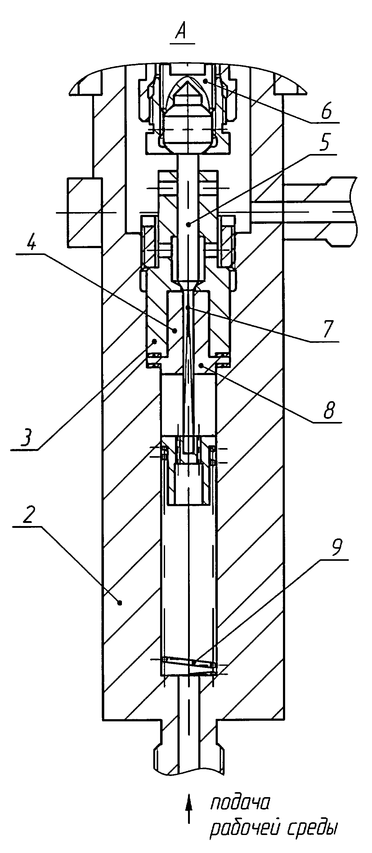
На фигуре изображен клапан регулирующий микрорасходный.The figure depicts a micro-flow control valve.
Клапан содержит МИМ 1, корпус 2 с установленными в нем седлом 3 с цилиндрической вставкой 4, запорную часть плунжера 5, шток 6, регулирующую часть плунжера 7, втулку 8 и пружину 9.The valve comprises a MIM 1, a housing 2 with a seat 3 mounted therein with a cylindrical insert 4, a locking part of the plunger 5, a stem 6, a regulating part of the plunger 7, a sleeve 8 and a spring 9.
Клапан работает следующим образом.The valve operates as follows.
При давлении управляющего воздуха в МИМ 1(в случае применения МИМ обратного действия) ниже нижней границы перестановочного диапазона запорная часть плунжера 5 находится в нижнем положении , т.е. клапан закрыт. При увеличении управляющего давления в МИМ выше нижней границы перестановочного диапазона запорная часть плунжера 5 поднимается, клапан открывается, обеспечивая расход рабочей среды через клапан, регулирующаяWhen the control air pressure in MIM 1 (in the case of applying MIM reverse action) below the lower boundary of the permutation range, the locking part of the plunger 5 is in the lower position, i.e. valve is closed. When the control pressure in the MIM increases above the lower boundary of the permutation range, the shut-off part of the plunger 5 rises, the valve opens, providing a flow of the working medium through the control valve
({fi({fi
часть плунжера 7 следует за запорной частью плунжера 5, т.к. она поджимается к последней пружиной 9 через втулку 8. Перемещение регулирующей части плунжера 7 приводит к увеличению площади открытого сечения в затворе увеличению расхода рабочей среды через клапан. Увеличение управляющего давления в МИМ до верхней границы перестановочного диапазона приводит к соверщению плунжером полного хода и увеличению расхода через клапан до наибольшего.Таким образом, изменению управляющего давления в МИМ в пределах перестановочного диапазона соответствует полный ход плунжера и , соответственно, изменение расхода от наименьшего до наибольшего. Требуемый расход через кпапан задается установкой соответствующего управляющего давления в МИМ.part of the plunger 7 follows the locking part of the plunger 5, because it is pressed to the last spring 9 through the sleeve 8. Moving the regulating part of the plunger 7 leads to an increase in the open cross-sectional area in the valve, an increase in the flow rate of the working medium through the valve. An increase in the control pressure in the MIM to the upper limit of the permutation range leads to a full stroke of the plunger and an increase in the flow rate through the valve to the maximum. Thus, a change in the control pressure in the MIM within the permutation range corresponds to the full stroke of the plunger and, accordingly, a change in flow from the smallest to the largest . The required flow rate through the valve is set by setting the appropriate control pressure in the MIM.
Проведенные испытания показали, что предлагаемая полезная модель обеспечивает:The tests showed that the proposed utility model provides:
-снижение затрат при изготовлении клапана за счет упрощения конструкции;- cost reduction in the manufacture of the valve due to the simplification of the design;
-технологичность изготовления клапана, т.к. при раздельном выполнении запорной и регулирующей частей плунжера не требуется выдерживать высокие требования к соосности цилиндрических поверхностей соответственно запорной и регулирующей частей плунжера, направляющего отверстия для плунжера в седле и отверстия в цилиндрической вставке для регулирующей части плунжера, потому что смещение взаимодействующих торцов запорной и регулирующей частей плунжера позволяет компенсировать их несоосность без ущерба для процесса регулирования;-the manufacturability of the valve, because when separately performing the locking and regulating parts of the plunger, it is not necessary to maintain high requirements for the alignment of the cylindrical surfaces, respectively, of the locking and regulating parts of the plunger, the guide holes for the plunger in the saddle and the holes in the cylindrical insert for the regulating part of the plunger, because the displacement of the interacting ends of the locking and regulating parts of the plunger allows you to compensate for their misalignment without compromising the regulatory process;
- снижение времени и затрат на восстановление работоспособного состояния клапана, т.к. при износе регулирующей части плунжера и цилиндрической вставки заменяются только указанные детали.- reduction of time and costs for the restoration of the operational state of the valve, because when the regulating part of the plunger and cylindrical insert is worn, only the specified parts are replaced.
dJiWd1f6 SBdJiWd1f6 SB
Claims (1)
Priority Applications (1)
| Application Number | Priority Date | Filing Date | Title |
|---|---|---|---|
| RU2002116583/20U RU26257U1 (en) | 2002-06-26 | 2002-06-26 | VALVE REGULATING MICROFLOW |
Applications Claiming Priority (1)
| Application Number | Priority Date | Filing Date | Title |
|---|---|---|---|
| RU2002116583/20U RU26257U1 (en) | 2002-06-26 | 2002-06-26 | VALVE REGULATING MICROFLOW |
Publications (1)
| Publication Number | Publication Date |
|---|---|
| RU26257U1 true RU26257U1 (en) | 2002-11-20 |
Family
ID=38316804
Family Applications (1)
| Application Number | Title | Priority Date | Filing Date |
|---|---|---|---|
| RU2002116583/20U RU26257U1 (en) | 2002-06-26 | 2002-06-26 | VALVE REGULATING MICROFLOW |
Country Status (1)
| Country | Link |
|---|---|
| RU (1) | RU26257U1 (en) |
Cited By (1)
| Publication number | Priority date | Publication date | Assignee | Title |
|---|---|---|---|---|
| RU2728774C1 (en) * | 2019-10-07 | 2020-07-31 | Федеральное государственное бюджетное образовательное учреждение высшего образования "Ярославский государственный технический университет" ФГБОУВО "ЯГТУ" | Micro flow control straight valve |
-
2002
- 2002-06-26 RU RU2002116583/20U patent/RU26257U1/en active Protection Beyond IP Right Term
Cited By (1)
| Publication number | Priority date | Publication date | Assignee | Title |
|---|---|---|---|---|
| RU2728774C1 (en) * | 2019-10-07 | 2020-07-31 | Федеральное государственное бюджетное образовательное учреждение высшего образования "Ярославский государственный технический университет" ФГБОУВО "ЯГТУ" | Micro flow control straight valve |
Similar Documents
| Publication | Publication Date | Title |
|---|---|---|
| US5314164A (en) | Pivotal diaphragm, flow control valve | |
| US2511844A (en) | Fluid flow control device | |
| US2750960A (en) | Valve | |
| US3498321A (en) | Self-sealing valve assembly | |
| US3561472A (en) | Check valve with restricted backflow | |
| US3538942A (en) | Control valve and cartridge unit | |
| RU26257U1 (en) | VALVE REGULATING MICROFLOW | |
| KR100745486B1 (en) | Constant flow control valve having a multi-function | |
| EP3158242B1 (en) | Valve, particularly servo valve | |
| US2608213A (en) | Pilot controlled diaphragm-type valve | |
| RU99845U1 (en) | LINEAR VALVE | |
| US20060027771A1 (en) | Reciprocating ball type angle valve | |
| CN2549268Y (en) | Unitary adjusting valve with new flow-path | |
| CN201651464U (en) | Automatic constant-current/pressure valve | |
| RU206860U1 (en) | STOP VALVE | |
| RU45495U1 (en) | BALL VALVE | |
| RU2116538C1 (en) | Shut-off adjusting single-seat valve | |
| RU100170U1 (en) | LINEAR VALVE | |
| CN110220014B (en) | Low operating torque high pressure stop valve | |
| RU151614U1 (en) | VALVE | |
| RU3308U1 (en) | BELLOW VALVE | |
| WO2022127577A1 (en) | Z-shaped liquid control valve without diaphragm, shaft, bushing, or spring | |
| CN108413110B (en) | A kind of valve | |
| CN208750129U (en) | Push buttonvalve | |
| CN210357890U (en) | High-pressure glue switch valve body |
Legal Events
| Date | Code | Title | Description |
|---|---|---|---|
| ND1K | Extending utility model patent duration | ||
| ND1K | Extending utility model patent duration |
Extension date: 20150626 |