ОБЛАСТЬ ИЗОБРЕТЕНИЯFIELD OF THE INVENTION
Объект настоящего изобретения в целом относится к устройствам для доставки лекарственных препаратов пациенту через кожу с использованием узла микроигл. An object of the present invention generally relates to devices for delivering drugs to a patient through the skin using a microneedle assembly.
ПРЕДПОСЫЛКИ ИЗОБРЕТЕНИЯBACKGROUND OF THE INVENTION
Ранее были разработаны многочисленные устройства трансдермальной доставки лекарств и других лекарственных соединений с использованием узлов микроигл. Микроиглы имеют преимущество вызывать меньшую боль у пациента по сравнению с более крупными традиционными иглами. Кроме того, традиционная подкожная (часто внутримышечная) доставка лекарств через иглу служит для доставки больших количеств лекарства единовременно, тем самым часто создавая всплеск биодоступности лекарства. Для лекарств с определенными метаболическими профилями это не является серьезной проблемой. Тем не менее многие лекарства оказывают благоприятное воздействие при наличии равновесной концентрации в потоке крови пациента; хорошо известным примером такого лекарства является инсулин. Устройства трансдермальной доставки лекарств технически способны медленно вводить лекарства с постоянной скоростью в течение продолжительного периода времени. Таким образом, устройства трансдермальной доставки лекарств имеют несколько преимуществ по сравнению с традиционными подкожными способами доставки лекарств.Numerous transdermal drug and drug delivery devices using microneedle nodes have previously been developed. Microneedles have the advantage of causing less pain in the patient compared to larger traditional needles. In addition, the traditional subcutaneous (often intramuscular) delivery of drugs through the needle serves to deliver large quantities of the drug at a time, thereby often creating a surge in the bioavailability of the drug. For drugs with specific metabolic profiles, this is not a serious problem. Nevertheless, many drugs have a beneficial effect when there is an equilibrium concentration in the patient’s blood stream; A well-known example of such a medicine is insulin. Transdermal drug delivery devices are technically capable of slowly administering drugs at a constant rate over an extended period of time. Thus, transdermal drug delivery devices have several advantages over traditional subcutaneous drug delivery methods.
Тем не менее существующие устройства трансдермальной доставки лекарств часто не способны стабильно доставлять все лекарство под роговой слой кожи таким образом, чтобы оно могло всасываться в организм. В связи с этим, из-за небольшого размера иглы чаще всего все или часть лекарства доставляется только в верхнюю часть кожи или в роговой слой, где лекарство не может всасываться в организм пациента. Это может произойти по разным причинам. Например, глубина введения иглы может немного переместиться назад относительно желаемой глубины введения не будет достигнута, например, из-за несоответствующего приложения усилия к иглам или естественной эластичность кожи, выталкивающей иглы наружу после введения. Кроме того, сложностью трансдермальной доставки такими маленькими иглами является то, что кожа может образовывать такое непроходимое место соединения с иглой, что лекарство течет вверх вдоль иглы к точке введения и в противоположную сторону от клеточных слоев, способных всасывать лекарство в организм. However, existing transdermal drug delivery devices are often not able to stably deliver the entire drug under the stratum corneum of the skin so that it can be absorbed into the body. In this regard, due to the small size of the needle most often all or part of the drug is delivered only to the upper part of the skin or to the stratum corneum, where the medicine cannot be absorbed into the patient's body. This can happen for a variety of reasons. For example, the depth of insertion of the needle may move slightly backward relative to the desired depth of insertion and will not be achieved, for example, due to inappropriate application of force to the needles or the natural elasticity of the skin pushing the needles out after insertion. In addition, the complexity of transdermal delivery with such small needles is that the skin can form such an impassable junction with the needle that the drug flows up along the needle to the injection point and in the opposite direction from the cell layers that can absorb the drug into the body.
Соответственно, остается потребность в устройстве трансдермальной доставки лекарств, обладающем улучшенной способностью стабильно и эффективно доставлять лекарственный препарат через кожу пациента. Accordingly, there remains a need for a transdermal drug delivery device having improved ability to deliver the drug stably and efficiently through the skin of a patient.
КРАТКОЕ ОПИСАНИЕ ИЗОБРЕТЕНИЯSUMMARY OF THE INVENTION
Аспекты и преимущества настоящего изобретения будут частично изложены в последующем описании, или могут быть очевидны из описания, или могут быть изучены посредством практического применения изобретения.Aspects and advantages of the present invention will be set forth in part in the description that follows, or may be apparent from the description, or may be learned by practice of the invention.
В одном аспекте объект настоящего изобретения относится к устройству трансдермальной доставки лекарств. Устройство может содержать корпус, содержащий верхнюю часть корпуса и нижнюю часть корпуса. Нижняя часть корпуса может определять нижнюю поверхность, содержащую средство крепления к коже для разъемного крепления нижней части корпуса к коже пользователя. Верхняя часть корпуса может по меньшей мере частично окружать центральную область устройства. Устройство может также содержать узел микроигл и резервуар, расположенные в центральной области. Резервуар может сообщаться c возможностью переноса жидкости с узлом микроигл. Кроме того, устройство может содержать толкающий элемент, расположенный над узлом микроигл в центральной области. Толкающий элемент может быть выполнен с возможностью обеспечения непрерывного двухстороннего усилия, имеющего направленную вниз составляющую, передаваемую через узел микроигл, и направленную вверх составляющую, передаваемую через средство крепления к коже. In one aspect, an object of the present invention relates to a transdermal drug delivery device. The device may include a housing containing the upper part of the housing and the lower part of the housing. The lower part of the body may define a lower surface containing skin attachment means for releasably attaching the lower part of the body to the skin of the user. The upper part of the housing may at least partially surround the central region of the device. The device may also comprise a microneedle assembly and a reservoir located in a central region. The reservoir may communicate with the possibility of transferring fluid to the microneedle assembly. In addition, the device may include a pushing member located above the microneedle assembly in the central region. The pushing member may be configured to provide a continuous two-way force having a downward component transmitted through the microneedle assembly and an upward component transmitted through the skin attachment means.
В другом аспекте объект настоящего изобретения относится к устройству трансдермальной доставки лекарств. Устройство может содержать верхний корпус, прикрепленный к нижнему корпусу, определяющему полость. Нижний корпус может определять нижнюю поверхность, содержащую средство крепления к коже для разъемного крепления нижнего корпуса к коже пользователя. Нижний корпус может также определять отверстие и может окружать узел микроигл. Устройство может быть выполнено таким образом, что нижний корпус отделен от узла микроигл. Кроме того, устройство может содержать резервуар, расположенный внутри полости, которая сообщается c возможностью переноса жидкости с узлом микроигл. Кроме того, устройство может содержать толкающий элемент, расположенный внутри полости между узлом микроигл и верхним корпусом. Толкающий элемент может быть выполнен таким образом, чтобы быть отделенным от нижнего корпуса, и может обеспечить (i) непрерывное усилие, имеющее направленную вниз составляющую, отделенную от верхнего и нижнего корпусов, передаваемую через узел микроигл на кожу пользователя; (ii) непрерывное усилие, имеющее направленную вверх составляющую, отделенную от узла микроигл, передаваемую на нижний корпус. In another aspect, an object of the present invention relates to a transdermal drug delivery device. The device may include an upper case attached to a lower case defining a cavity. The lower case may define a lower surface comprising skin attachment means for releasably attaching the lower case to a user's skin. The lower case may also define an opening and may surround the microneedle assembly. The device can be made in such a way that the lower case is separated from the microneedle assembly. In addition, the device may include a reservoir located inside the cavity, which communicates with the possibility of transferring fluid to the microneedle assembly. In addition, the device may include a pushing member located inside the cavity between the microneedle assembly and the upper body. The pushing member may be configured to be separate from the lower case, and may provide (i) a continuous force having a downward component separated from the upper and lower bodies, transmitted through the microneedle assembly to the user's skin; (ii) a continuous force having an upward component separated from the microneedle assembly and transmitted to the lower housing.
В другом аспекте объект настоящего изобретения относится к способу трансдермальной доставки лекарственного препарата. Способ в целом может включать размещение устройства трансдермальной доставки лекарств смежно с кожей; крепление корпуса устройства к коже с помощью средства крепления к коже; приложение посредством толкающего элемента непрерывного двухстороннего усилия, имеющего направленную вниз составляющую, передаваемую через узел микроигл устройства, и направленную вверх составляющую, передаваемую через средство крепления к коже; доставку лекарственного препарата через узел микроигл в или через кожу. In another aspect, an object of the present invention relates to a method for transdermal drug delivery. The method as a whole may include placing the transdermal drug delivery device adjacent to the skin; attaching the body of the device to the skin using means of attachment to the skin; the application by means of a pushing member of a continuous two-sided force having a downwardly directed component transmitted through the microneedle assembly of the device and an upwardly directed component transmitted through the skin attachment means; drug delivery through the microneedle site to or through the skin.
Эти и другие признаки, аспекты и преимущества настоящего изобретения станут более понятны со ссылкой на последующее описание и прилагаемую формулу изобретения. Прилагаемые графические материалы, которые включены в и составляют часть данного описания, иллюстрируют варианты осуществления изобретения и вместе с описанием служат для объяснения принципов изобретения.These and other features, aspects and advantages of the present invention will become more apparent with reference to the following description and the attached claims. The accompanying graphic materials, which are included in and form part of this description, illustrate embodiments of the invention and together with the description serve to explain the principles of the invention.
КРАТКОЕ ОПИСАНИЕ ГРАФИЧЕСКИХ МАТЕРИАЛОВBRIEF DESCRIPTION OF GRAPHIC MATERIALS
Полное и достаточное раскрытие настоящего изобретения, предназначенное для специалиста в данной области техники, изложено в описании изобретения, которое ссылается на представленные чертежи, на которых:A complete and sufficient disclosure of the present invention, intended for a person skilled in the art, is set forth in the description of the invention, which refers to the presented drawings, in which:
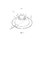
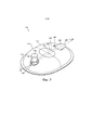
на фиг. 1 показан вид в перспективе одного варианта осуществления устройства трансдермальной доставки лекарств в собранном виде в соответствии с аспектами объекта настоящего изобретения;in FIG. 1 is a perspective view of one embodiment of an assembled transdermal drug delivery device in accordance with aspects of an aspect of the present invention;
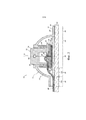
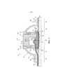
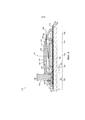
на фиг. 2 показан вид в поперечном сечении устройства, показанного на фиг. 1, который выполнен по линии 2-2, иллюстрирующий, в частности, различные компоненты устройства в незадействованном положении;in FIG. 2 shows a cross-sectional view of the device shown in FIG. 1, which is taken along line 2-2, illustrating, in particular, the various components of the device in an idle position;
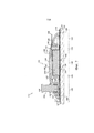
на фиг. 3 показан другой вид в поперечном сечении устройства, показанного на фиг. 1, который выполнен по линии 2-2, иллюстрирующий, в частности, различные компоненты устройства в задействованном положении; in FIG. 3 shows another cross-sectional view of the device shown in FIG. 1, which is taken along line 2-2, illustrating, in particular, the various components of the device in the engaged position;
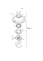
на фиг. 4 показан покомпонентный вид в перспективе устройства, показанного на фиг. 1-3; in FIG. 4 is an exploded perspective view of the apparatus of FIG. 1-3;
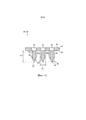
на фиг. 5 показан вид в перспективе другого варианта осуществления устройства трансдермальной доставки лекарств в собранном виде в соответствии с аспектами объекта настоящего изобретения;in FIG. 5 is a perspective view of another embodiment of an assembled transdermal drug delivery device in accordance with aspects of an aspect of the present invention;
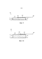
на фиг. 6 показан вид в поперечном сечении устройства, показанного на фиг. 5, который выполнен по линии 6-6, иллюстрирующий, в частности, различные компоненты устройства в незадействованном положении;in FIG. 6 is a cross-sectional view of the device shown in FIG. 5, which is taken along lines 6-6, illustrating, in particular, various components of the device in an idle position;
на фиг. 7 показан другой вид в поперечном сечении устройства, показанного на фиг. 6, иллюстрирующий, в частности, различные компоненты устройства в задействованном положении; in FIG. 7 shows another cross-sectional view of the device shown in FIG. 6, illustrating, in particular, the various components of the device in the engaged position;
на фиг. 8 показан покомпонентный вид в перспективе устройства, показанного на фиг. 5-7; in FIG. 8 is an exploded perspective view of the apparatus of FIG. 5-7;
на фиг. 9 показан вид в поперечном сечении двухстороннего толкающего элемента устройства, показанного на фиг. 5-8, иллюстрирующий, в частности, двухсторонний толкающий элемент в незадействованном или нерасширенном положении;in FIG. 9 is a cross-sectional view of the double-sided pushing member of the device of FIG. 5-8, illustrating, in particular, a two-way pushing member in an idle or unexpanded position;
на фиг. 10 показан другой вид в поперечном сечении двухстороннего толкающего элемента устройства, показанного на фиг. 5-8, иллюстрирующий, в частности, двухсторонний толкающий элемент в задействованном или расширенном положении; иin FIG. 10 shows another cross-sectional view of the double-sided pushing member of the device shown in FIG. 5-8, illustrating, in particular, a two-way pushing member in an engaged or extended position; and
на фиг. 11 показан частичный вид в увеличенном масштабе одного варианта осуществления конструкции узла микроигл, пригодной для использования с раскрытым устройством трансдермальной доставки лекарств. in FIG. 11 is a partial enlarged view of one embodiment of a microneedle assembly design suitable for use with the disclosed transdermal drug delivery device.
ПОДРОБНОЕ ОПИСАНИЕ ИЗОБРЕТЕНИЯDETAILED DESCRIPTION OF THE INVENTION
Далее будет сделана ссылка в развернутой форме на варианты осуществления изобретения, один или несколько примеров которых показаны в графическом материале. Каждый пример приведен для пояснения настоящего изобретения и не ограничивает его. В действительности, специалистам в данной области техники ясно, что в настоящее изобретение могут быть внесены различные модификации и изменения без отступления от объема или сущности изобретения. Например, признаки, показанные или описанные как часть одного варианта осуществления, могут быть использованы в другом варианте для получения еще одного варианта осуществления. Таким образом, имеется в виду, что настоящее изобретение охватывает такие модификации и изменения, которые подпадают под объем прилагаемой формулы изобретения и ее эквивалентов. Reference will now be made in expanded form to embodiments of the invention, one or more examples of which are shown in the graphic material. Each example is provided to illustrate the present invention and does not limit it. In fact, it will be apparent to those skilled in the art that various modifications and changes may be made to the present invention without departing from the scope or spirit of the invention. For example, features shown or described as part of one embodiment may be used in another embodiment to provide another embodiment. Thus, it is intended that the present invention covers such modifications and variations as come within the scope of the appended claims and their equivalents.
В целом, объект настоящего изобретения относится к устройству трансдермальной доставки лекарств, выполненному с возможностью доставки лекарственного препарата в и/или через кожу пользователя. Устройство в общем случае может содержать корпус, выполненный с возможностью закрытия или окружения различных компонентов устройства, с по меньшей мере частью корпуса, выполненной с возможностью крепления к коже пользователя. Устройство может также содержать резервуар, сообщающийся c возможностью переноса жидкости с узлом микроигл. Резервуар в целом может быть выполнен с возможностью удерживания лекарства для последующей доставки через кожу пользователя посредством узла микроигл. Кроме того, устройство может содержать толкающий элемент, выполненный с возможностью приложения непрерывного двухстороннего усилия через устройство. В частности, в некоторых вариантах осуществления толкающий элемент может быть выполнен с возможностью приложения непрерывного направленного вниз усилия через узел микроигл для вталкивания микроигл узла в кожу пользователя. Одновременно толкающий элемент может быть выполнен с возможностью приложения к корпусу непрерывного направленного вверх усилия, которое передается через корпус на кожу пользователя (посредством подходящего средства крепления к коже, расположенного между корпусом и кожей), обеспечивая тем самым усилие натяжения, которое натягивает кожу пользователя вокруг узла микроигл для улучшения введения и поддержания микроигл в/внутри кожи. In general, an object of the present invention relates to a transdermal drug delivery device configured to deliver a drug to and / or through a user's skin. The device in General, may include a housing made with the possibility of closing or surrounding various components of the device, with at least part of the housing made with the possibility of attachment to the skin of the user. The device may also contain a reservoir in communication with the possibility of transferring fluid to the microneedle assembly. The reservoir as a whole can be configured to hold the drug for subsequent delivery through the skin of the user through the microneedle assembly. In addition, the device may include a pushing member configured to apply continuous two-way force through the device. In particular, in some embodiments, the pushing member may be configured to apply a continuous downward force through the microneedle assembly to push the microneedle assembly into the skin of the user. At the same time, the pushing element can be configured to apply a continuous upward force to the housing, which is transmitted through the housing to the skin of the user (by means of suitable means of attachment to the skin located between the housing and the skin), thereby providing a tension force that pulls the skin of the user around the assembly microneedles to improve the introduction and maintenance of microneedles in / inside the skin.
Теперь обратимся к графическим материалам; на фиг. 1-4 показано несколько видов одного из вариантов осуществления устройства 10 трансдермальной доставки лекарств в соответствии с аспектами объекта настоящего изобретения. Как показано, устройство 10 может содержать наружный корпус 12, выполненный с возможностью по меньшей мере частично окружать и/или закрывать различные компоненты устройства 10. В целом корпус 12 может содержать верхнюю часть 14 корпуса и нижнюю часть 16 корпуса, образующую единое целое с и/или проходящую от верхней части 14 корпуса. Верхняя часть 14 корпуса в целом может быть выполнена с возможностью определения открытого объема для размещения различных компонентов устройства. Например, как показано фиг. 2 и 3, когда устройство 10 помещают на кожу 18 пользователя, открытый объем, в котором могут вмещаться компоненты устройства, может быть определен между кожей 18 пользователя и верхней частью 14 корпуса. Следует учесть, что верхняя часть 14 корпуса в целом может быть выполнена с возможностью определения любой подходящей формы. Например, как показано в изображенном варианте осуществления, верхняя часть 14 корпуса определяет полукруглую или куполообразную форму. Тем не менее в других вариантах осуществления верхняя часть 14 корпуса может иметь любую другую подходящую форму, которая определяет открытый объем для размещения различных компонентов устройства 10.Now let's turn to graphic materials; in FIG. 1 to 4 are several views of one embodiment of a transdermal drug delivery device 10 in accordance with aspects of an aspect of the present invention. As shown, the device 10 may include an outer casing 12 configured to at least partially surround and / or close the various components of the device 10. In general, the casing 12 may comprise an upper casing part 14 and a lower casing part 16 integrally with and / or passing from the upper part 14 of the housing. The upper part 14 of the housing as a whole can be made with the possibility of determining the open volume to accommodate various components of the device. For example, as shown in FIG. 2 and 3, when the device 10 is placed on the skin of the user 18, an open volume in which the components of the device can fit can be defined between the skin of the user 18 and the upper part 14 of the housing. It should be noted that the upper part 14 of the housing as a whole can be configured to determine any suitable shape. For example, as shown in the depicted embodiment, the upper part 14 of the body defines a semicircular or domed shape. However, in other embodiments, the upper housing portion 14 may have any other suitable shape that defines an open volume for accommodating various components of the device 10.
Нижняя часть 16 корпуса 12 обычно может быть выполнена с возможностью расположения смежно с кожей пользователя при использовании устройства 10. Например, как показано в изображенном варианте осуществления, нижняя часть 16 корпуса может быть выполнена в виде фланца или выступа, проходящего наружу от нижней периферии верхней части 14 корпуса таким образом, что нижняя поверхность 20 нижней части 16 корпуса может проходить непосредственно смежно с кожей 18 пользователя. Кроме того, в некоторых вариантах осуществления нижняя часть 16 корпуса может быть выполнена с возможностью крепления к коже 18 пользователя с использованием любого подходящего средства крепления к коже. Например, в одном варианте осуществления на нижнюю поверхность 20 нижней части 16 корпуса может быть нанесен клейкий слой 22. Таким образом, когда устройство 10 помещают на кожу 18 пользователя, корпус 12 может быть прикреплен к коже 18 посредством клейкого слоя 20. Тем не менее в других вариантах осуществления любые другие подходящие средства крепления к коже, известные в данной области техники, могут быть использованы для крепления корпуса 12 к коже 18 пользователя.The lower part 16 of the housing 12 can usually be arranged to be adjacent to the skin of the user when using the device 10. For example, as shown in the illustrated embodiment, the lower part 16 of the housing can be made in the form of a flange or protrusion extending outward from the lower periphery of the upper part 14 of the housing in such a way that the lower surface 20 of the lower portion 16 of the housing can pass directly adjacent to the skin 18 of the user. In addition, in some embodiments, the lower housing portion 16 may be fastened to the skin of the user 18 using any suitable means of fastening to the skin. For example, in one embodiment, an adhesive layer 22 may be applied to the lower surface 20 of the lower housing portion 16. Thus, when the device 10 is placed on the skin of the user 18, the housing 12 may be attached to the skin 18 by the adhesive layer 20. However, in in other embodiments, any other suitable skin attachment means known in the art can be used to attach the housing 12 to the skin 18 of the user.
Кроме того, как показано, в частности, на фиг. 2 и 3, различные зоны или области устройства 10 могут быть определены посредством и/или в пределах корпуса 12. Например, устройство 10 может содержать центральную область 30, определенную вокруг его центральной линии 31. Устройство 10 может также содержать внешнюю область 32, в целом определенную по периферии устройства в месте, в котором устройство 10 крепится к коже 18 пользователя. Например, как показано на фиг. 2 и 3, внешняя область 32 может быть определена на границе между нижней поверхностью 20 нижней части 18 корпуса и клейким слоем 22, крепящим корпус 12 к коже 18 пользователя. Кроме того, устройство 10 может содержать промежуточную область 34, проходящую между и отделяющую центральную и внешнюю области 30, 32.In addition, as shown in particular in FIG. 2 and 3, various zones or areas of the device 10 can be defined by and / or within the housing 12. For example, the device 10 may comprise a central region 30 defined around its center line 31. The device 10 may also comprise an outer region 32, in general defined at the periphery of the device at the place where the device 10 is attached to the skin 18 of the user. For example, as shown in FIG. 2 and 3, the outer region 32 can be defined at the boundary between the lower surface 20 of the lower part 18 of the housing and the adhesive layer 22 securing the housing 12 to the skin 18 of the user. In addition, the device 10 may comprise an intermediate region 34 extending between and separating the central and external regions 30, 32.
В некоторых вариантах осуществления устройство 10 может содержать один или несколько компонентов, по меньшей мере частично расположенных внутри центральной области 30. Например, как показано в изображенном варианте осуществления, устройство 10 содержит узел 36 микроигл, резервуар 38 и двухсторонний толкающий элемент 40, вертикально выровненные в центральной области 30, при этом вертикальная проекция таких компонентов в целом определяет внешний периметр центральной области 30. Как будет описано ниже, толкающий элемент 40 может быть выполнен с возможностью приложения направленного вниз усилия через центральную область 30 с целью вжатия узла 36 микроигл в кожу 18 пользователя. Кроме того, толкающий элемент 40 также может быть выполнен с возможностью приложения направленного вверх усилия через центральную область 30, которое передается через корпус 12 на внешнюю область 32 устройства 10, обеспечивая тем самым направленное вверх усилие относительно кожи 18 пользователя посредством клейкого слоя 22.In some embodiments, the device 10 may comprise one or more components at least partially located within the central region 30. For example, as shown in the illustrated embodiment, the device 10 comprises a microneedle assembly 36, a reservoir 38, and a double-sided push member 40 vertically aligned the central region 30, with the vertical projection of such components generally defining the outer perimeter of the central region 30. As will be described below, the pushing member 40 may be formed with zmozhnostyu application of downward force through the central region 30 with the aim to press assembly 36 of microneedles 18 into the skin of the user. In addition, the pushing member 40 may also be configured to exert an upward force through the central region 30, which is transmitted through the housing 12 to the outer region 32 of the device 10, thereby providing an upward force with respect to the skin 18 of the user by means of the adhesive layer 22.
В целом узел 36 микроигл устройства 10 может иметь любую подходящую конструкцию, известную в данной области техники, для доставки жидкого лекарственного препарата в и/или через кожу 18 пользователя, например, путем выполнения с возможностью размещения множества микроигл, проходящих наружу из подходящей подложки или опоры. Например, вид в частичном поперечном сечении одного из вариантов осуществления подходящей конструкции узла микроигл показан на фиг. 11. Как показано, узел 36 микроигл может содержать опору 42, определяющую верхнюю поверхность 44 и нижнюю поверхность 46, и множество микроигл 48, проходящих наружу из нижней поверхности 46. Опора 42 обычно может быть изготовлена из жесткого, полужесткого или гибкого листового материала, такого как металлический материал, керамический материал, пластмассовый материал и/или любой другой подходящий материал. Кроме того, опора 42 может определять одно или несколько отверстий между своими верхней и нижней поверхностями 44, 46 для обеспечения протекания лекарственного препарата между ними. Например, как показано на фиг. 11, одно отверстие 50 может быть определено в опоре 42 на месте каждой микроиглы 48 для обеспечения доставки лекарственного препарата от верхней поверхности 44 к такой микроигле 48. Тем не менее в других вариантах осуществления опора 42 может определять любое другое подходящее количество отверстий 50, расположенных на и/или на расстоянии от места каждой микроиглы 48.In general, the microneedle assembly 36 of the device 10 may have any suitable structure known in the art for delivering a liquid drug to and / or through the skin of a user 18, for example, by arranging multiple microneedles extending outward from a suitable substrate or support . For example, a partial cross-sectional view of one embodiment of a suitable microneedle assembly design is shown in FIG. 11. As shown, the microneedle assembly 36 may include a support 42 defining an upper surface 44 and a lower surface 46, and a plurality of microneedles 48 extending outward from the lower surface 46. The support 42 may typically be made of rigid, semi-rigid, or flexible sheet material such such as metallic material, ceramic material, plastic material and / or any other suitable material. In addition, the support 42 may define one or more holes between its upper and lower surfaces 44, 46 to ensure the flow of the drug between them. For example, as shown in FIG. 11, one hole 50 may be defined in a support 42 in place of each microneedle 48 to ensure drug delivery from the upper surface 44 to such a microneedle 48. However, in other embodiments, the support 42 may define any other suitable number of holes 50 located on and / or at a distance from each microneedle 48.
Кроме того, как показано на фиг. 11, каждая микроигла 48 узла 36 микроигл может быть в целом выполнена с возможностью определения острой или игольчатой формы (например, конической или пирамидальной формы или цилиндрической формы, переходящей в коническую или пирамидальную форму), проходящей между основанием 52, расположенным смежно с и/или проходящим от нижней поверхности 46 опоры 42, и наконечником 54, расположенным напротив основания 52. В целом, понимается, что наконечник 52 может соответствовать точке каждой микроиглы 48, которая расположена дальше всего от опоры 42 и может определять наименьший размер каждой микроиглы 48. Кроме того, каждая микроигла 48 в целом может определять любую подходящую длину 51 между ее основанием 52 и наконечником 52, которой достаточно для обеспечения возможности проникновения микроигл 48 в роговой слой и их прохождения в эпидермис. В некоторых вариантах осуществления может быть целесообразным ограничить длину 51 микроигл 48 таким образом, чтобы они не проникали через внутреннюю поверхность эпидермиса и в дерму; такие варианты осуществления преимущественно помогают свести к минимуму боль для пациента, получающего лекарственный препарат. Например, в одном варианте осуществления каждая микроигла 48 может определять длину 51, составляющую менее чем приблизительно 1000 микрометров (мкм), например менее чем приблизительно 800 мкм, или менее чем приблизительно 750 мкм, или менее чем приблизительно 500 мкм, а также из любых других поддиапазонов между ними. В конкретном варианте осуществления длина 51 может находиться в диапазоне от приблизительно 25 мкм до приблизительно 1000 мкм, например от приблизительно 100 мкм до приблизительно 1000 мкм или от приблизительно 200 мкм до приблизительно 1000 мкм, а также в любых других поддиапазонах между ними. Furthermore, as shown in FIG. 11, each microneedle 48 of the microneedle assembly 36 can be generally configured to define a sharp or needle shape (for example, a conical or pyramidal shape or a cylindrical shape turning into a conical or pyramidal shape) extending between a base 52 adjacent to and / or extending from the bottom surface 46 of the support 42, and the tip 54 located opposite the base 52. In general, it is understood that the tip 52 can correspond to the point of each microneedle 48, which is located farthest from the support 42 and can determine divide the smallest size of each microneedle 48. In addition, each microneedle 48 as a whole can determine any suitable length 51 between its base 52 and tip 52, which is sufficient to allow microneedles 48 to penetrate into the stratum corneum and pass into the epidermis. In some embodiments, it may be appropriate to limit the length of 51 microneedles 48 so that they do not penetrate the inner surface of the epidermis and into the dermis; such embodiments advantageously help minimize pain for the patient receiving the drug. For example, in one embodiment, each microneedle 48 may determine a length 51 of less than about 1000 micrometers (μm), for example, less than about 800 μm, or less than about 750 μm, or less than about 500 μm, as well as any other subbands between them. In a particular embodiment, the length 51 may range from about 25 microns to about 1000 microns, for example from about 100 microns to about 1000 microns, or from about 200 microns to about 1000 microns, as well as in any other subbands between them.
Следует понимать, что длина 51 микроигл 48 может варьироваться в зависимости от места, в котором раскрытое устройство используется на пользователе. Например, длина микроигл 48 для устройства, которое будет использоваться на ноге пользователя, может значительно отличаться от длины микроигл 48 для устройства, которое будет использоваться на руке пользователя. It should be understood that the length 51 of the microneedles 48 may vary depending on the place in which the disclosed device is used on the user. For example, the length of microneedles 48 for a device that will be used on the user's leg may vary significantly from the length of microneedles 48 for a device that will be used on a user's hand.
Кроме того, каждая микроигла 48 может в целом определять любое подходящее соотношение размеров (т. е. длины 51 к поперечному размеру 53 каждой микроиглы 48). Тем не менее в некоторых вариантах осуществления соотношение размеров может быть больше чем 2, например больше чем 3 или больше чем 4. Следует понимать, что в случаях, в которых поперечный размер 53 (например, ширина, диаметр и т. д.) изменяется по длине каждой микроиглы 26 (например, как показано на фиг. 11), соотношение размеров может быть определено на основе среднего поперечного размера 53. In addition, each microneedle 48 can generally determine any suitable size ratio (i.e., a length 51 to a transverse dimension 53 of each microneedle 48). However, in some embodiments, the aspect ratio may be greater than 2, for example greater than 3 or greater than 4. It should be understood that in cases in which the transverse dimension 53 (for example, width, diameter, etc.) varies according to the length of each microneedle 26 (for example, as shown in Fig. 11), the aspect ratio can be determined based on the average transverse size 53.
Кроме того, каждая микроигла 48 может определять один или несколько каналов 56, сообщающихся c возможностью переноса жидкости с отверстиями 50, определенными в опоре 42. В целом каналы 56 могут быть определены в любом подходящем месте на и/или в пределах каждой микроиглы 48. Например, как показано на фиг. 11, в одном варианте осуществления каналы 56 могут быть определены вдоль наружной поверхности каждой микроиглы 48. В другом варианте осуществления каналы 56 могут быть определены через внутреннюю часть микроиглы 48 таким образом, что каждая микроигла 48 образует полый вал. Несмотря на это, в целом каналы 56 могут быть выполнены с возможностью образования пути, который позволяет лекарственному препарату течь от верхней поверхности 44 опоры 42 через отверстия 50 и в каналы 56, в результате чего лекарственный препарат может быть доставлен в и/или через кожу 18 пользователя. In addition, each microneedle 48 can define one or more channels 56 communicating with the possibility of transferring liquid with openings 50 defined in the support 42. In general, channels 56 can be defined at any suitable location on and / or within each microneedle 48. For example as shown in FIG. 11, in one embodiment, the channels 56 can be defined along the outer surface of each microneedle 48. In another embodiment, the channels 56 can be defined through the interior of the microneedle 48 so that each microneedle 48 forms a hollow shaft. Despite this, in general, the channels 56 can be configured to form a path that allows the drug to flow from the upper surface 44 of the support 42 through the holes 50 and into the channels 56, as a result of which the drug can be delivered to and / or through the skin 18 user.
Следует понимать, что каналы 56 могут быть выполнены с возможностью определения любой подходящей формы поперечного сечения. Например, в одном варианте осуществления каждый канал 56 может определять полукруглую или круглую форму. В другом варианте осуществления каждый канал 56 может определять некруглую форму, такую как V-образная форма или любая другая подходящая форма поперечного сечения.It should be understood that the channels 56 may be configured to determine any suitable cross-sectional shape. For example, in one embodiment, each channel 56 may define a semicircular or circular shape. In another embodiment, each channel 56 may define a non-circular shape, such as a V-shape or any other suitable cross-sectional shape.
В некоторых вариантах осуществления размеры каналов 56, определенные микроиглами 48, могут быть специально выбраны, чтобы вызвать капиллярное течение лекарственного препарата. Как в целом понимается, капиллярное течение возникает, когда силы адгезии текучей среды относительно стенок канала больше, чем когезионные силы между молекулами жидкости. В частности, капиллярное давление в канале обратно пропорционально поперечному размеру канала и прямо пропорционально поверхностной энергии соответствующей текучей среды, умноженной на косинус краевого угла текучей среды на границе раздела, определенной между текучей средой и каналом. Таким образом, чтобы способствовать капиллярному течению лекарственного препарата через узел 36 микроигл, поперечный размер 58 (фиг. 11) канала (каналов) 56 (например, диаметр, ширина и т. д.) может быть выборочно отрегулирован, при этом меньший размер в целом приводит к повышению капиллярного давления. Например, в некоторых вариантах осуществления поперечный размер 58 может быть выбран таким образом, чтобы площадь поперечного сечения каждого канала 56 находилась в диапазоне от приблизительно 1000 квадратных микрон (мкм²) до приблизительно 125000 мкм², например от приблизительно 1250 мкм² до приблизительно 60000 мкм² или от приблизительно 6000 мкм² до приблизительно 20000 мкм², а также в любых других поддиапазонах между ними. In some embodiments, channel sizes 56 defined by microneedles 48 may be specifically selected to cause capillary flow of the drug. As is generally understood, capillary flow occurs when the adhesion forces of the fluid relative to the channel walls are greater than the cohesive forces between the liquid molecules. In particular, the capillary pressure in the channel is inversely proportional to the transverse size of the channel and directly proportional to the surface energy of the corresponding fluid, multiplied by the cosine of the boundary angle of the fluid at the interface defined between the fluid and the channel. Thus, in order to facilitate the capillary flow of the drug through the microneedle assembly 36, the transverse dimension 58 (FIG. 11) of the channel (s) 56 (for example, diameter, width, etc.) can be selectively adjusted, while the overall size is smaller leads to an increase in capillary pressure. For example, in some embodiments, the transverse dimension 58 may be selected so that the cross-sectional area of each channel 56 is in the range from about 1000 square microns (μm²) to about 125000 μm², for example from about 1250 μm² to about 60000 μm², or from about 6000 μm² to approximately 20,000 μm², as well as any other sub-bands between them.
Следует понимать, что на фиг. 11 показана только часть подходящей конструкции узла микроигл, и, таким образом, узел 36 микроигл, применяемый в устройстве 10, может в целом содержать любое количество микроигл 48, выступающих из его опоры 42. Например, в одном варианте осуществления фактическое количество микроигл 48, содержащихся в узле 36 микроигл, может находиться в диапазоне от приблизительно 10 микроигл на квадратный сантиметр (см2) до приблизительно 1500 микроигл на см2, например от приблизительно 50 микроигл на см2 до приблизительно 1250 микроигл на см2 или от приблизительно 100 микроигл на см2 до приблизительно 500 микроигл на см2, а также в любых других поддиапазонах между ними. It should be understood that in FIG. 11 shows only part of a suitable microneedle assembly design, and thus the microneedle assembly 36 used in the device 10 may generally comprise any number of microneedles 48 protruding from its support 42. For example, in one embodiment, the actual number of microneedles 48 contained at node 36 microneedles, can range from about 10 microneedles per square centimeter (cm 2 ) to about 1500 microneedles per cm 2 , for example from about 50 microneedles per cm 2 to about 1250 microneedles per cm 2, or from about 10 0 microneedles per cm 2 to about 500 microneedles per cm 2 , as well as in any other subbands between them.
Также следует понимать, что микроиглы 48 в целом могут быть расположены на опоре 42 по множеству разных схем размещения, и такие схемы размещения могут быть разработаны для любого конкретного использования. Например, в одном варианте осуществления микроиглы 48 могут быть равномерно разнесены друг от друга, например по прямоугольной или квадратной сетке или по концентрическим окружностям. В таком варианте осуществления промежуток между микроиглами 48 обычно может зависеть от многих факторов, включая длину и ширину микроигл 48, но не ограничиваясь ими, а также от количества и типа лекарственного препарата, предназначенного для доставки через микроиглы 48. В качестве неограничивающего примера группы микроигл, подходящие для использования в настоящем изобретении, содержат те, которые описаны в WO2012/020332 автора Ross; WO2001/0270221 автора Ross; и WO2011/070457 автора Ross. It should also be understood that microneedles 48 as a whole can be positioned on a support 42 in a plurality of different placement patterns, and such placement patterns can be designed for any particular use. For example, in one embodiment, microneedles 48 may be uniformly spaced from each other, for example along a rectangular or square grid or in concentric circles. In such an embodiment, the spacing between microneedles 48 may typically depend on many factors, including but not limited to the length and width of microneedles 48, as well as the amount and type of drug to be delivered through microneedles 48. As a non-limiting example of a group of microneedles, suitable for use in the present invention, contain those described in WO2012 / 020332 by Ross; WO2001 / 0270221 by Ross; and WO2011 / 070457 by Ross.
Возвращаясь к фиг. 1-4, как указано выше, раскрытое устройство 10 может также содержать резервуар 38, сообщающийся с возможность переноса жидкости с узлом 36 микроигл. В частности, как показано на фиг. 2 и 3, резервуар 38 может быть расположен над узлом 36 микроигл в центральной области 30 устройства 10. В некоторых вариантах осуществления резервуар 38 может быть выполнен с возможностью крепления к части узла 36 микроигл. Например, как показано на фиг. 2 и 3, клейкий слой 60 может быть расположен между нижней поверхностью 62 резервуара 38 и верхней поверхностью узла 36 микроигл (т. е. верхней поверхностью 44 опоры 42) с целью крепления узла 36 микроигл к резервуару 38.Returning to FIG. 1-4, as described above, the disclosed device 10 may also comprise a reservoir 38 in fluid communication with the microneedle assembly 36. In particular, as shown in FIG. 2 and 3, the reservoir 38 may be located above the microneedle assembly 36 in the central region 30 of the device 10. In some embodiments, the reservoir 38 may be adapted to be attached to a portion of the microneedle assembly 36. For example, as shown in FIG. 2 and 3, the adhesive layer 60 may be located between the lower surface 62 of the reservoir 38 and the upper surface of the microneedle assembly 36 (i.e., the upper surface 44 of the support 42) to attach the microneedle assembly 36 to the reservoir 38.
В целом резервуар 38 может иметь любую подходящую конструкцию и/или может быть выполнен из любого подходящего материала, который обеспечивает первоначальное удержание лекарственного препарата в резервуаре 38 до его последующей доставки в узел 36 микроигл. Таким образом, следует учесть, что используемый в данной заявке термин "резервуар" может в целом относиться к любому подходящему специально отведенному месту или камере в устройстве 10, которые выполнены с возможностью удержания жидкого лекарственного препарата. Например, как показано в изображенном варианте осуществления, резервуар 38 может быть выполнен в виде жесткого или полужесткого элемента, определяющего открытый объем или полость 64 для удержания лекарственного препарата. Тем не менее в других вариантах осуществления резервуар 38 может иметь любую другую подходящую конструкцию. Например, в другом варианте осуществления резервуар 38 может быть выполнен в виде эластичного баллона. В другом варианте осуществления резервуар 38 может быть выполнен в виде твердого контейнера или матрицы, через которые может быть направлен лекарственный препарат, таких как проницаемая, полупроницаемая или микропористая твердая матрицы. В еще одном варианте осуществления резервуар 38 может содержать эластичный баллон, содержащийся в или защищенный жестким элементом. In general, the reservoir 38 may be of any suitable design and / or may be made of any suitable material that provides initial retention of the drug in the reservoir 38 until it is subsequently delivered to the microneedle assembly 36. Thus, it should be appreciated that the term “reservoir” as used in this application may generally refer to any suitable, specially designated place or chamber in device 10 that is configured to hold a liquid drug. For example, as shown in the depicted embodiment, the reservoir 38 may be made in the form of a rigid or semi-rigid element defining an open volume or cavity 64 for holding the drug. However, in other embodiments, reservoir 38 may be of any other suitable design. For example, in another embodiment, the reservoir 38 may be in the form of an elastic balloon. In another embodiment, reservoir 38 may be in the form of a solid container or matrix through which a drug can be directed, such as a permeable, semipermeable, or microporous solid matrix. In yet another embodiment, the reservoir 38 may comprise an elastic balloon contained in or protected by a rigid member.
Следует понимать, что любой подходящий лекарственный препарат (препараты) может удерживаться в резервуаре 38, а затем доставляться через кожу 18 пользователя посредством узла 36 микроигл. Используемый в данной заявке термин "лекарственный препарат" используется в самом широком смысле и может включать любой препарат (например, препарат в чистом виде) и/или любой раствор, эмульсию, суспензию и/или тому подобное, содержащие лекарство (лекарства), но не ограничивается ими. Точно так же термин "лекарство" используется в самом широком смысле и включает любое соединение, имеющее или воспринимаемое как имеющее лечебный эффект, которое может включать как сертифицированные, так и несертифицированные соединения. Например, подходящие типы лекарств могут включать биопрепараты, низкомолекулярные средства, вакцины, белковые соединения, противоинфекционные средства, гормоны, соединения, регулирующие действие сердечной мышцы или ток крови, обезболивающие средства и так далее, но не ограничиваются ими. Специалисту в данной области техники должно быть понятно, что различные компоненты могут быть объединены вместе любым подходящим способом, чтобы получить соединение, имеющее или воспринимаемое как имеющее лечебный эффект. It should be understood that any suitable drug (s) can be held in the reservoir 38 and then delivered through the skin 18 of the user through the node 36 microneedles. Used in this application, the term "drug" is used in the broadest sense and may include any drug (for example, the drug in its purest form) and / or any solution, emulsion, suspension and / or the like containing the drug (s), but not limited to them. Similarly, the term “drug” is used in its broadest sense and includes any compound that has or is perceived as having a therapeutic effect, which may include both certified and non-certified compounds. For example, suitable types of drugs may include, but are not limited to, biologics, low molecular weight agents, vaccines, protein compounds, anti-infective agents, hormones, compounds that regulate the action of the heart muscle or blood flow, painkillers, and so on. One of ordinary skill in the art will appreciate that the various components can be combined together in any suitable way to produce a compound that has or is perceived to have a therapeutic effect.
Также следует понимать, что лекарственный препарат может подаваться в резервуар 38 различными способами. Например, в некоторых вариантах осуществления лекарственный препарат может подаваться через впускной канал 66, определенный через часть резервуара 38. В таком варианте подходящий патрубок, канал или трубка 68 (например, трубка с микроотверстием или любая другая подходящая гибкая трубка) могут быть выполнены с возможностью размещения во впускном канале 66 и могут сообщаться c возможностью переноса жидкости с подходящим источником лекарств (например, шприцем, содержащим лекарственный препарат) таким образом, что лекарственный препарат может быть направлен через впускной канал 66 в резервуар 38. В других вариантах осуществления лекарственный препарат может подаваться в резервуар 38 с помощью любого другого подходящего средства/способа. Например, резервуар 38 может быть выполнен с возможностью предварительного заполнения или предварительной загрузки до того, как он будет вмонтирован в устройство 10. It should also be understood that the drug can be delivered to reservoir 38 in various ways. For example, in some embodiments, the medicament may be delivered through an inlet 66 defined through a portion of the reservoir 38. In such an embodiment, a suitable tube, channel or tube 68 (for example, a micro-hole tube or any other suitable flexible tube) may be arranged inlet 66 and can be in fluid communication with a suitable source of medication (for example, a syringe containing the drug) so that the drug can be directed through the inlet 66 to the reservoir 38. In other embodiments, the drug may be delivered to the reservoir 38 by any other suitable means / method. For example, the reservoir 38 may be configured to pre-fill or pre-load before it is mounted in the device 10.
Кроме того, как, в частности, показано на фиг. 4, устройство 10 может также содержать мембрану 70 управления скоростью, расположенную между резервуаром 38 и узлом 36 микроигл. В целом, мембрана 70 управления скоростью может быть выполнена с возможностью замедления или управления иным образом скоростью тока лекарственного препарата при его высвобождении из резервуара 38. Конкретные материалы, толщина и т. д. мембраны 70 управления скоростью могут, конечно, изменяться в зависимости от множества факторов, таких как вязкость лекарственного препарата, требуемое время доставки и т. д.Furthermore, as shown in particular in FIG. 4, the device 10 may also comprise a speed control membrane 70 located between the reservoir 38 and the microneedle assembly 36. In general, the speed control membrane 70 can be configured to slow down or otherwise control the flow rate of the drug when it is released from the reservoir 38. The specific materials, thickness, etc. of the speed control membrane 70 can, of course, vary depending on the plurality factors such as drug viscosity, required delivery time, etc.
В некоторых вариантах осуществления мембрана 70 управления скоростью может быть изготовлена из любого подходящего проницаемого, полупроницаемой или микропористого материала (материалов). Например, в некоторых вариантах материал, используемый для формирования мембраны 70 управления скоростью, может иметь средний размер пор от приблизительно 0,01 микрона до приблизительно 1000 микрон, например от приблизительно 1 микрона до приблизительно 500 микрон или от приблизительно 20 микрон до приблизительно 200 микрон, а также из любых других поддиапазонов между ними. Кроме того, в конкретном варианте осуществления материал, используемый для формирования мембраны 70 управления скоростью, может иметь средний размер пор от приблизительно 0,01 микрона до приблизительно 1 микрона, например от приблизительно 0,1 микрона до приблизительно 0,9 микрона или от приблизительно 0,25 микрона до приблизительно 0,75 микрона, а также из любых других поддиапазонов между ними. Подходящие материал для мембраны включают, например, рулонные волокнистые материалы (например, тканые или нетканые), перфорированные пленки, пены, губки и т. д., которые образованы из полимеров, таких как полиэтилен, полипропилен, поливинилацетат, этилен н-бутилацетат и сополимеры этилена и винилацетата. In some embodiments, the implementation of the membrane 70 speed control can be made of any suitable permeable, semi-permeable or microporous material (materials). For example, in some embodiments, the material used to form the speed control membrane 70 may have an average pore size of from about 0.01 microns to about 1000 microns, for example from about 1 micron to about 500 microns, or from about 20 microns to about 200 microns, as well as from any other subbands between them. In addition, in a particular embodiment, the material used to form the speed control membrane 70 may have an average pore size of from about 0.01 microns to about 1 microns, for example from about 0.1 microns to about 0.9 microns, or from about 0 , 25 microns to about 0.75 microns, as well as from any other sub-bands between them. Suitable membrane materials include, for example, rolled fibrous materials (e.g., woven or non-woven), perforated films, foams, sponges, etc., which are formed from polymers such as polyethylene, polypropylene, polyvinyl acetate, ethylene n-butyl acetate and copolymers ethylene and vinyl acetate.
Возвращаясь к фиг. 1-4, устройство 10 может также содержать поршень 72, расположенный непосредственно над резервуаром 38. В целом поршень 72 может быть выполнен с возможностью перемещения относительно корпуса 12, когда различные компоненты, содержащиеся внутри корпуса 12, перемещаются между незадействованным положением (на фиг. 2), в котором нижняя часть узла 36 микроигл в целом выровнена с или утоплена относительно нижней поверхности 20 нижней части 16 корпуса, и задействованным положением (на фиг. 3), в котором узел 36 микроигл проходит наружу за пределы нижней поверхности 20 нижней части 16 корпуса, таким образом обеспечивая проникновение микроигл 48 узла 36 в кожу 18 пользователя. Как показано на фиг. 2-4, в одном варианте осуществления поршень 72 может в целом иметь цилиндрическую верхнюю часть 74, выполненную с возможностью размещения со скольжением в соответствующем отверстии 76, определенном в корпусе 12, и уплощенную нижнюю часть 78, выполненную с возможностью входить в зацепление или по-другому располагаться непосредственно смежно с резервуаром 38. В таком варианте осуществления, когда поршень 72 перемещается вниз относительно корпуса 12, нижняя часть 78 поршня 72 может прикладывать усилие к резервуару 38, который толкает узел 36 микроигл вниз в кожу 18 пользователя.Returning to FIG. 1-4, the device 10 may also comprise a piston 72 located directly above the reservoir 38. In general, the piston 72 may be movable relative to the housing 12 when various components contained within the housing 12 are moved between an unused position (in FIG. 2 ), in which the lower part of the microneedle assembly 36 is generally aligned with or recessed with respect to the lower surface 20 of the lower housing part 16, and the involved position (in FIG. 3), in which the microneedle assembly 36 extends outside the lower surface STI 20 of the lower body portion 16, thereby ensuring penetration node 36 microneedles 48 into the skin 18 by user. As shown in FIG. 2-4, in one embodiment, the piston 72 may generally have a cylindrical upper portion 74 configured to slide into a corresponding hole 76 defined in the housing 12 and a flattened lower portion 78 configured to engage or engage the other is directly adjacent to the reservoir 38. In such an embodiment, when the piston 72 moves downward relative to the housing 12, the lower portion 78 of the piston 72 can exert force on the reservoir 38, which pushes the microneedle assembly 36 18 of the skin member.
Кроме того, как указано выше, раскрытое устройство 10 может также содержать двухсторонний толкающий элемент 40, расположенный в центральной области 30 устройства 10. В целом толкающий элемент 40 может быть любым подходящим механизмом смещения и/или средством приложения усилия, выполненными с возможностью приложения непрерывного двухстороннего усилия (имеющего как направленную вниз составляющую, так направленную вверх составляющую) через устройство 10 к коже 18 пользователя. Например, как показано в изображенном варианте осуществления, толкающий элемент 40 содержит пружину, сжатую между корпусом 12 и поршнем 72. Таким образом, если устройство 10 перемещается в задействованное положение во время использования (фиг. 3), пружина может быть выполнена с возможностью приложения непрерывного двухстороннего усилия по отношению к корпусу 12 и поршню 72, которое передается через устройство 10 на кожу 18 пользователя. В частности, направленная вниз составляющая усилия (обозначена стрелками 84 на фиг. 3) может передаваться вниз через центральную область 30 устройства 10 (т. е. через поршень 72 и резервуар 38) на узел 36 микроигл таким образом, что микроиглы 48 узла 36 вдавливаются в и поддерживаются в коже 18 пользователя. Аналогичным образом направленная вверх составляющая усилия (обозначена стрелками 86 на фиг. 3) может быть передана вверх через центральную область 30 устройства 30 на корпус 12, тем самым отталкивая корпус 12 от кожи 18 пользователя. Однако, поскольку корпус 12 прикреплен к коже 18 пользователя вокруг его внешней периферии (т. е. во внешней области 32 устройства 10), то такое направленное вверх усилие может в целом быть передано через корпус 12 и клейкий слой 22, чтобы обеспечить направленное вверх усилие натяжения относительно кожи 18 пользователя. Таким образом, когда микроиглы 48 выталкиваются вниз в кожу 18 пользователя, кожа 18 пользователя может одновременно быть притянута вверх вокруг периферии устройства 10, таким образом, натягивая кожу 18 вокруг узла 36 микроигл и повышая легкость, с которой микроиглы 48 могут вводиться и поддерживаться в коже 18 пользователя. In addition, as described above, the disclosed device 10 may also include a two-way pushing member 40 located in the central region 30 of the device 10. In general, the pushing member 40 may be any suitable biasing mechanism and / or force applying means configured to apply a continuous two-way efforts (having both a downward component and an upward component) through the device 10 to the skin 18 of the user. For example, as shown in the illustrated embodiment, the pushing member 40 comprises a spring compressed between the housing 12 and the piston 72. Thus, if the device 10 moves to the engaged position during use (FIG. 3), the spring may be configured to continuously bilateral force with respect to the housing 12 and the piston 72, which is transmitted through the device 10 to the skin 18 of the user. In particular, the downward component of the force (indicated by arrows 84 in FIG. 3) can be transmitted downward through the central region 30 of the device 10 (i.e., through the piston 72 and reservoir 38) to the microneedle assembly 36 so that the microneedles 48 of the assembly 36 are pressed in and are supported in the skin of 18 user. Similarly, the upward component of the force (indicated by arrows 86 in FIG. 3) can be transmitted upward through the central region 30 of the device 30 to the housing 12, thereby pushing the housing 12 away from the user's skin 18. However, since the housing 12 is attached to the skin of the user 18 around its outer periphery (i.e., in the outer region 32 of the device 10), such an upward force can generally be transmitted through the housing 12 and the adhesive layer 22 to provide upward force tension relative to the skin of the 18 user. Thus, when microneedles 48 are pushed down into the skin of the user 18, the skin of the user 18 can simultaneously be pulled up around the periphery of the device 10, thereby pulling the skin 18 around the node 36 of the microneedles and increasing the ease with which the microneedles 48 can be inserted and maintained in the skin 18 users.
В некоторых вариантах осуществления устройство 10 может также содержать стопорный механизм, выполненный с возможностью поддержания компонентов устройства в незадействованном положении, если устройство 10 не используют. Например, как показано на фиг. 1, стопорный штифт 80 может быть выполнен с возможностью прохождения через отверстие 82, определенное в поршне 72, чтобы входить в зацепление с противоположными сторонами верхней части 14 корпуса, тем самым поддерживая пружину в сжатом или незадействованном состоянии. Однако, когда стопорный штифт 80 удаляют, пружина может быть разжата таким образом, что непрерывное двухстороннее усилие передается через устройство 10 на кожу 18 пользователя. В альтернативных вариантах осуществления стопорный механизм может иметь любую другую подходящую конструкцию и/или может быть связан с любым другим подходящим компонентом устройства 10. In some embodiments, the device 10 may also comprise a locking mechanism configured to maintain the components of the device in an idle position if the device 10 is not used. For example, as shown in FIG. 1, the locking pin 80 may be configured to extend through an opening 82 defined in the piston 72 so as to engage with opposite sides of the upper housing portion 14, thereby maintaining the spring in a compressed or idle state. However, when the locking pin 80 is removed, the spring can be released so that a continuous two-way force is transmitted through the device 10 to the skin 18 of the user. In alternative embodiments, the locking mechanism may be of any other suitable design and / or may be associated with any other suitable component of the device 10.
Следует отметить то, что в качестве альтернативы компоновке пружина/стопорный штифт 80 поршень 72 может быть перемещен между незадействованным и задействованным положениями с помощью любой другой подходящей компоновки и/или конструкции, известной в данной области техники. Например, в другом варианте осуществления верхняя часть 74 поршня 72, проходящая наружу за пределы верхушки верхней части 14 корпуса, может быть использована в качестве нажимной кнопки, чтобы вручную толкать поршень 72 вниз в задействованное положение. В таком варианте осуществления нижняя часть пружины 40 может, например, быть соединена с поршнем 72 таким образом, что пружина 40 смещает поршень 72 в незадействованное положение. It should be noted that, as an alternative to the spring / lock pin arrangement 80, the piston 72 can be moved between the unused and engaged positions using any other suitable arrangement and / or design known in the art. For example, in another embodiment, the upper part 74 of the piston 72 extending outwardly beyond the top of the upper part 14 of the housing can be used as a push button to manually push the piston 72 down into the engaged position. In such an embodiment, the lower part of the spring 40 may, for example, be connected to the piston 72 so that the spring 40 biases the piston 72 to an unused position.
Следует отметить то, что поскольку резервуар 38 может быть выполнен в виде жесткого или полужесткого элемента в изображенном варианте осуществления, усилие, прикладываемое толкающим элементом 40, передается через корпус резервуара 38 вместо того, чтобы передаваться собственно на лекарственный препарат. Соответственно, микроиглы 48 могут быть вжаты в кожу 18 пользователя без увеличения давления лекарственного препарата или иного приложения значительного направленного вниз усилия к лекарственному препарату. Иными словами, толкающий элемент 40 при приведении в действие и приложении направленного вниз усилия к узлу 36 микроигл не создает давление на сжиженное лекарство, проходящее из устройства в кожу через каналы 56 микроигл. It should be noted that since the reservoir 38 can be made in the form of a rigid or semi-rigid element in the depicted embodiment, the force exerted by the pushing element 40 is transmitted through the body of the reservoir 38 instead of being transmitted directly to the drug. Accordingly, microneedles 48 can be squeezed into the skin of a user 18 without increasing the pressure of the drug or otherwise applying a significant downward force to the drug. In other words, the pushing member 40, when actuating and applying a downward force to the microneedle assembly 36, does not exert pressure on the liquefied medicine passing from the device into the skin through the microneedle channels 56.
Обращаясь теперь к фиг. 5-10; показано несколько видов другого варианта осуществления устройства 110 трансдермальной доставки лекарств в соответствии с аспектами объекта настоящего изобретения. Как показано, устройство 110 может содержать наружный корпус 112, выполненный с возможностью по меньшей мере частично окружать и/или закрывать различные компоненты устройства 110. В целом, корпус 112 может содержать верхнюю часть 114 корпуса и нижнюю часть 116 корпуса. Однако, в отличие от корпуса 12, описанного выше со ссылкой на фиг. 1-4, верхняя часть 114 корпуса и нижняя часть 116 корпуса могут содержать отдельные компоненты, выполненные с возможностью крепления друг к другу по отдельности. Например, как показано на фиг. 6-8, в одном варианте осуществления нижняя периферийная поверхность 117 верхней части 114 корпуса может быть выполнена с возможностью крепления к верхней поверхности 118 нижней части 116 корпуса с помощью клея, термического скрепления/сварки или любого другого подходящего средства крепления. Turning now to FIG. 5-10; several types of another embodiment of a transdermal drug delivery device 110 are shown in accordance with aspects of an aspect of the present invention. As shown, the device 110 may include an outer casing 112 configured to at least partially surround and / or close the various components of the device 110. In general, the casing 112 may include an upper housing portion 114 and a lower housing portion 116. However, unlike the housing 12 described above with reference to FIG. 1-4, the upper part 114 of the housing and the lower part 116 of the housing may contain separate components, made with the possibility of fastening to each other separately. For example, as shown in FIG. 6-8, in one embodiment, the lower peripheral surface 117 of the upper housing part 114 may be adapted to be attached to the upper surface 118 of the lower housing part 116 by means of glue, thermal bonding / welding, or any other suitable fixing means.
В целом, верхняя часть 114 корпуса может быть выполнена в виде наружного корпуса, определяющего открытый объем для размещения различных компонентов устройства. Например, как показано фиг. 6 и 7, когда корпус 112 собран, между верхней частью 114 корпуса и нижней частью 116 корпуса может быть определен открытый объем, в котором могут по меньшей мере частично размещаться компоненты устройства. Следует понимать, что верхняя часть 114 корпуса может быть выполнена с возможностью определения любой подходящей формы. Например, как показано в изображенном варианте осуществления, верхняя часть 114 корпуса в целом определяет полукруглую или куполообразную форму. Тем не менее в других вариантах осуществления верхняя часть 114 корпуса может иметь любую другую подходящую форму, которая определяет открытый объем для размещения различных компонентов устройства 10.In General, the upper part 114 of the housing can be made in the form of an outer housing that defines the open volume to accommodate various components of the device. For example, as shown in FIG. 6 and 7, when the housing 112 is assembled, an open volume may be determined between the upper housing part 114 and the lower housing part 116 in which the components of the device can be at least partially placed. It should be understood that the upper part 114 of the housing may be configured to determine any suitable shape. For example, as shown in the depicted embodiment, the upper part 114 of the housing as a whole defines a semicircular or domed shape. However, in other embodiments, the upper housing portion 114 may have any other suitable shape that defines an open volume for accommodating various components of the device 10.
Нижняя часть 116 корпуса 112 может быть в целом выполнена с возможностью расположения смежно с кожей 18 пользователя при применении устройства 110. Например, как показано в изображенном варианте осуществления, нижняя часть 116 корпуса может содержать плоскую панель, выполненную с возможностью расширения как внутрь, так и наружу от нижней периферийной поверхности 117 верхней части 114 корпуса таким образом, что нижняя поверхность 120 нижней части 116 корпуса проходит непосредственно смежно с кожей 18 пользователя. Кроме того, как показано на фиг. 8, нижняя часть 116 корпуса может определять центральное отверстие 121, через которое может быть доступна кожа 18 пользователя. Например, как будет описано ниже, узел 136 микроигл устройства 110 может быть выполнен с возможностью прохождения через отверстие 121 для обеспечения проникновения такого узла в кожу 18 пользователя. The lower part 116 of the housing 112 can be generally arranged to be adjacent to the skin 18 of the user when the device 110 is used. For example, as shown in the illustrated embodiment, the lower part 116 of the housing can comprise a flat panel configured to expand both inwards and outward from the lower peripheral surface 117 of the upper housing portion 114 so that the lower surface 120 of the lower housing portion 116 extends directly adjacent to the user's skin 18. Furthermore, as shown in FIG. 8, the lower housing portion 116 may define a central opening 121 through which the user's skin 18 can be accessed. For example, as will be described below, the microneedle assembly 136 of the device 110 may be configured to pass through the opening 121 to allow such a assembly to penetrate the skin 18 of the user.
Кроме того, в некоторых вариантах осуществления нижняя часть 116 корпуса может быть выполнена с возможностью крепления к коже 18 пользователя с применением подходящего средства крепления к коже. Например, в одном варианте осуществления клей 122 может быть нанесен на нижнюю поверхность 120 нижней части 116 корпуса. Таким образом, когда устройство 10 помещают на кожу 18 пользователя, корпус 112 может быть прикреплен к коже 18 посредством клейкого слоя 122. Тем не менее в других вариантах осуществления для крепления корпуса 112 к коже 18 пользователя могут быть использованы любые другие подходящие средства крепления к коже, известные в данной области техники.In addition, in some embodiments, the lower housing portion 116 may be fastened to the skin of the user 18 using suitable skin fastening means. For example, in one embodiment, glue 122 may be applied to a lower surface 120 of a lower housing portion 116. Thus, when the device 10 is placed on the skin of the user 18, the housing 112 can be attached to the skin 18 by an adhesive layer 122. However, in other embodiments, any other suitable means of attachment to the skin can be used to attach the housing 112 to the skin of the user 18. known in the art.
Следует понимать, что в некоторых вариантах осуществления как верхняя часть 114 корпуса, так и нижняя часть 116 корпуса могут быть образованы из относительно гибкого материала, такого как гибкий полимерный материал, для обеспечения соответствия в целом корпуса 112 форме тела пользователя и/или для облегчения надлежащего приклеивания к коже 18. В таких вариантах осуществления устройство 110 может также содержать жесткий опорный элемент 124, проходящий между верхней и нижней частями 114, 116 корпуса, чтобы обеспечить опору конструкции устройства 110. Например, как показано на фиг. 8, опорный элемент 124 может определять относительно плоскую платформу 125. Плоская нижняя часть платформы 125 может в одном аспекте обеспечивать плоскую или по существу плоскую поверхность относительно двухстороннего толкающего элемента таким образом, чтобы двухсторонний толкающий элемент мог достичь надежного и/или равномерного зацепления с этой поверхностью при привидении в действие. Кроме того, опорный элемент 124 может дополнительно содержать внешний выступ 126, проходящий вверх из платформы 125. Кроме того, как показано на фиг. 8, верхняя часть 114 корпуса может быть выполнена с возможностью определения посадочного отверстия 128, выполненного с возможностью размещения выступа 126. Таким образом, когда выступ 126 размещен в посадочном отверстии 128, по меньшей мере часть верхней части 114 корпуса может находиться в контакте с и поддерживаться платформой 125. Кроме того, верхняя часть опорного элемента 124 может также обеспечить несущую нагрузку поверхность, через которую пользователем может быть приложено усилие при креплении устройства 110 к коже 18 пользователя.It should be understood that in some embodiments, both the upper housing portion 114 and the lower housing portion 116 may be formed from a relatively flexible material, such as a flexible polymeric material, to ensure that the entire housing 112 conforms to the user's body shape and / or to facilitate proper sticking to the skin 18. In such embodiments, the device 110 may also comprise a rigid support member 124 extending between the upper and lower parts 114, 116 of the housing to support the structure of the device 110. H For example, as shown in FIG. 8, the support member 124 may define a relatively flat platform 125. The flat lower portion of the platform 125 may, in one aspect, provide a flat or substantially flat surface relative to the two-sided pushing member so that the two-sided pushing member can achieve reliable and / or uniform engagement with this surface at ghostly action. In addition, the support member 124 may further comprise an external protrusion 126 extending upward from the platform 125. In addition, as shown in FIG. 8, the upper housing portion 114 may be configured to define a landing hole 128 configured to accommodate the protrusion 126. Thus, when the protrusion 126 is placed in the landing hole 128, at least a portion of the upper housing portion 114 may be in contact with and supported platform 125. In addition, the top of the support member 124 can also provide a load-bearing surface through which the user can exert force when attaching the device 110 to the skin 18 of the user.
Как и в варианте осуществления, описанном выше со ссылкой на фиг. 1-4, устройство 110 может содержать различные зоны или области, определенные посредством и/или в пределах корпуса 112. Например, как показано на фиг. 6 и 7, устройство 110 может содержать центральную область 130, определенный вокруг его осевой линии 131. Устройство 110 также может содержать внешнюю область 132, в целом определенную в месте, в котором устройство 110 прикреплено к коже 18 пользователя. Например, как показано на фиг. 6 и 7, внешняя область 132 может быть определена на границе между нижней поверхностью 120 нижней части 116 корпуса и клейким слоем 122. Кроме того, устройство 110 может также содержать промежуточную область 134, проходящую между и разделяющую центральную и внешнюю области 130, 132.As in the embodiment described above with reference to FIG. 1-4, device 110 may comprise various zones or areas defined by and / or within housing 112. For example, as shown in FIG. 6 and 7, the device 110 may comprise a central region 130 defined around its center line 131. The device 110 may also comprise an outer region 132 generally defined at the location where the device 110 is attached to the skin 18 of the user. For example, as shown in FIG. 6 and 7, the outer region 132 can be defined at the boundary between the lower surface 120 of the lower housing portion 116 and the adhesive layer 122. In addition, the device 110 may also include an intermediate region 134 extending between and separating the central and outer regions 130, 132.
В некоторых вариантах осуществления устройство 110 может содержать один или несколько компонентов, по меньшей мере частично расположенных внутри центральной области 130. Например, как показано в изображенном варианте осуществления, устройство 110 может содержать узел 136 микроигл, резервуар 138 и двухсторонний толкающий элемент 140, вертикально выровненные в центральной области 130, при этом вертикальная проекция узла 136 микроигл и толкающего элемента 140 в целом определяет внешний периметр центральной области 130. Как будет описано ниже, толкающий элемент 140 может быть выполнен с возможностью приложения направленного вниз усилия через центральную область 130 с целью вжатия узла 136 микроигл в кожу 18 пользователя. Кроме того, толкающий элемент 140 также может быть выполнен с возможностью приложения направленного вверх усилия через центральную область 130, которое передается через корпус 112 на внешнюю область 132 устройства 110, обеспечивая тем самым направленное вверх усилие относительно кожи 18 пользователя посредством клейкого слоя 122.In some embodiments, device 110 may comprise one or more components at least partially located within central region 130. For example, as shown in the illustrated embodiment, device 110 may comprise microneedle assembly 136, reservoir 138, and double-sided push member 140 vertically aligned in the central region 130, the vertical projection of the microneedle assembly 136 and the pushing member 140 as a whole defines the outer perimeter of the central region 130. As will be described below, the pushing the element 140 may be configured to apply a downward force through the central region 130 to compress the microneedle assembly 136 into the skin 18 of the user. In addition, the pushing member 140 may also be configured to exert an upward force through the central region 130, which is transmitted through the housing 112 to the outer region 132 of the device 110, thereby providing an upward force with respect to the skin 18 of the user through the adhesive layer 122.
В целом узел 136 микроигл может быть выполнен так же или аналогично узлу 36 микроигл, описанному выше. Например, как показано на фиг. 11, в некоторых вариантах осуществления узел 136 микроигл может содержать опору 42, содержащую верхнюю поверхность 44 и нижнюю поверхность 46 и определяющую множество отверстий 50 между верхней и нижней поверхностями 44, 46. Кроме того, узел 136 микроигл может также содержать множество микроигл 48, проходящих наружу из нижней поверхности 46. Как описано выше, каждая микроигла 48 может определять канал (каналы) 56, сообщающиеся c возможностью переноса жидкости с отверстиями 50. Таким образом, лекарственный препарат, содержащийся в устройстве 110, может быть направлен от верхней поверхности 44 опоры 42 через отверстия 50 в микроиглы 48 для последующей доставки к коже 18 пользователя. In general, the microneedle assembly 136 can be made in the same way or similarly to the microneedle assembly 36 described above. For example, as shown in FIG. 11, in some embodiments, the microneedle assembly 136 may include a support 42 comprising an upper surface 44 and a lower surface 46 and defining a plurality of holes 50 between the upper and lower surfaces 44, 46. In addition, the microneedle assembly 136 may also comprise a plurality of microneedles 48 extending outward from the bottom surface 46. As described above, each microneedle 48 can define a channel (s) 56, communicating with the possibility of transferring fluid with holes 50. Thus, the drug contained in the device 110 may be apravlen from the upper surface 44 of the support 42 through the holes 50 in the microneedles 48 for subsequent delivery to the skin of the user 18.
Кроме того, аналогично варианту осуществления, описанному выше, резервуар 138 устройства 110 может быть выполнен в целом в виде любого подходящего специально отведенного места или камеры, в которых лекарственный препарат может первоначально удерживаться до последующей доставки препарата к узлу 136 микроигл. Например, как показано в изображенном варианте осуществления, резервуар 138 может быть выполнен в виде эластичного баллона. В частности, как показано на фиг. 8, резервуар 138 может содержать гибкий верхний слой 142 и гибкий нижний слой 144, при этом верхний и нижний слои 142, 144 выполнены с возможностью крепления друг к другу по своим краям 146. В таком варианте осуществления для обеспечения доставки лекарственного препарата, удерживаемого в резервуаре 138, в узел 136 микроигл нижний слой 144 резервуара 138 может определять отверстие или окно 148, которое сообщается c возможностью переноса жидкости с узлом 136 микроигл. Например, как показано на фиг. 8, окно 148 может быть определено в нижнем слое 144 так, что когда резервуар 138 расположен непосредственно над узлом 136 микроигл, то лекарственный препарат может быть направлен через окно 148 и вдоль верхней поверхности узла 136 микроигл (т. е. верхней поверхности 44 опоры 42). In addition, similarly to the embodiment described above, the reservoir 138 of the device 110 can be configured as a whole in any suitable specially designated location or chamber in which the drug can initially be held until the drug is subsequently delivered to the microneedle assembly 136. For example, as shown in the depicted embodiment, the reservoir 138 may be made in the form of an elastic balloon. In particular, as shown in FIG. 8, the reservoir 138 may comprise a flexible upper layer 142 and a flexible lower layer 144, wherein the upper and lower layers 142, 144 are adapted to be attached to each other at their edges 146. In such an embodiment, to ensure the delivery of a drug held in the reservoir 138, into the microneedle assembly 136, the bottom layer 144 of the reservoir 138 may define an opening or window 148 that is in fluid communication with the microneedle assembly 136. For example, as shown in FIG. 8, a window 148 can be defined in the lower layer 144 so that when the reservoir 138 is located directly above the microneedle assembly 136, the drug can be directed through the window 148 and along the upper surface of the microneedle assembly 136 (i.e., the upper surface 44 of the support 42 )
Следует понимать, что лекарственный препарат может поступать в резервуар 138 разными способами. Например, в некоторых вариантах осуществления лекарственный препарат может подаваться через впускное отверстие 150, определенной в верхнем слое 142 (или нижнем слое 144) резервуара 138. В таком варианте осуществления подходящий патрубок, канал и/или трубка могут сообщаться c возможностью переноса жидкости как с впускным отверстием 150, так и с подходящим источником лекарств (например, шприцем, содержащим лекарственный препарат) таким образом, что лекарственный препарат может быть направлен через впускное отверстие 150 в резервуар 138. Например, как показано на фиг. 6-8, питающий канал 152 может содержать нижний конец 154, выполненный с возможностью крепления/пайки к резервуару 138 вокруг впускного отверстия 140 таким образом, что лекарственный препарат может быть доставлен к впускному отверстию 150 через подающий канал 156, определенный нижним концом 154. Кроме того, как показано на фиг. 5, верхний конец 158 питающего канала 152 может быть выполнен с возможностью прохождения через отверстие 160 для канала, определенное в верхней части 114 корпуса. Таким образом, верхний конец 158 может быть доступен пользователю или медицинскому работнику для обеспечения введения лекарственного препарата в питающий канал 152. Хотя это не показано, питающий канал 152 также может быть выполнен содержащим обратный клапан, чтобы обеспечить протекание лекарственного препарата через канал 152 в направлении резервуара 138 (т. е. от верхнего конца 158 к нижнему концу 154) и для предотвращения протекания такого лекарственного препарата в противоположном направлении (т. е. от нижнего конца 154 к верхнему концу 158). It should be understood that the drug may enter reservoir 138 in various ways. For example, in some embodiments, the drug may be delivered through an inlet 150 defined in the upper layer 142 (or lower layer 144) of the reservoir 138. In such an embodiment, a suitable pipe, channel, and / or tube may be in fluid communication with the inlet hole 150, and with a suitable source of drugs (for example, a syringe containing a drug) so that the drug can be directed through the inlet 150 into the reservoir 138. For example, as shown in FIG. 6-8, the feed channel 152 may include a lower end 154 that is capable of fastening / soldering to the reservoir 138 around the inlet 140 so that the drug can be delivered to the inlet 150 through the feed channel 156 defined by the lower end 154. In addition as shown in FIG. 5, the upper end 158 of the supply channel 152 may be configured to pass through a channel hole 160 defined in the upper housing portion 114. Thus, the upper end 158 may be accessible to the user or health care provider to allow the drug to be introduced into the supply channel 152. Although not shown, the supply channel 152 may also be provided with a check valve to allow the drug to flow through the channel 152 towards the reservoir 138 (i.e., from the upper end 158 to the lower end 154) and to prevent the flow of such a drug in the opposite direction (i.e., from the lower end 154 to the upper end 158).
В других вариантах осуществления лекарственный препарат может подаваться в резервуар 138 с помощью любого другого подходящего средства/способа. Например, в одном варианте осуществления резервуар 138 может быть выполнен с возможностью предварительного заполнения или предварительной загрузки перед его монтажом в устройство 10. In other embodiments, the drug may be delivered to reservoir 138 by any other suitable means / method. For example, in one embodiment, the reservoir 138 may be configured to pre-fill or pre-load before being installed in the device 10.
Кроме того, раскрытое устройство 110 может также содержать мембрану 170 управления скоростью для замедления или контроля иным образом скорости потока лекарственного препарата при его высвобождении в узел 136 микроигл. В частности, как показано на фиг. 8, мембрана 170 управления скоростью может быть выполнена с возможностью закрепления внутри резервуара 138 по периметру окна 148 резервуара таким образом, чтобы лекарственный препарат проходил через мембрану 170 управления скоростью перед выходом из резервуара 138 через окно 148. Тем не менее в других вариантах осуществления мембрана 170 управления скоростью может быть расположена между нижним слоем 144 резервуара 138 и узлом 136 микроигл в месте, где находится окно 148. Следует учитывать, что мембрана 170 управления скоростью в целом может быть выполнена в виде такой же или аналогичной мембраны 70 управления скоростью, описанной выше, например будучи изготовленной из любого подходящего проницаемого, полупроницаемого или микропористого материала (материалов), что обеспечивает мембрану 170 возможностью контролировать скорость потока лекарственного препарата, протекающего между резервуаром 138 и узлом 136 микроигл. In addition, the disclosed device 110 may also include a speed control membrane 170 to slow or otherwise control the flow rate of the drug when it is released to the microneedle assembly 136. In particular, as shown in FIG. 8, the velocity control membrane 170 may be configured to be secured within the reservoir 138 around the perimeter of the reservoir window 148 so that the drug passes through the velocity control membrane 170 before exiting the reservoir 138 through the window 148. However, in other embodiments, the membrane 170 the speed control can be located between the bottom layer 144 of the reservoir 138 and the node 136 microneedles in the place where the window 148. It should be borne in mind that the membrane 170 of the speed control as a whole can be performed in the form of the same or similar velocity control membrane 70 described above, for example, made of any suitable permeable, semipermeable, or microporous material (s), which allows the membrane 170 to control the flow rate of the drug flowing between reservoir 138 and microneedle assembly 136.
Возвращаясь к фиг. 5-10; как указано выше, устройство 110 может также содержать двухсторонний толкающий элемент 140, расположенный в центральной области 130 устройства 110. В целом, толкающий элемент 140 может содержать любой подходящий механизм смещения и/или средство приложения усилия, выполненные с возможностью приложения непрерывного двухстороннего усилия (имеющего как направленную вниз составляющую, так и направленную вверх составляющую) через устройство 110 к коже 18 пользователя. Например, как показано в изображенном варианте осуществления, толкающий элемент 140 содержит расширяемый элемент, расположенный между верхней частью 114 корпуса и резервуаром 138. Расширяемый элемент в целом может быть выполнен с возможностью нахождения в нерасширенном состоянии (фиг. 6 и 9), в котором элемент не передает никаких усилий через центральную область 130 устройства 100, и в расширенном или задействованном состоянии (фиг. 7 и 10), в котором элемент расширяется наружу для того, чтобы приложить непрерывное двухстороннее усилие через центральную область 130. Например, как, в частности, показано на фиг. 9 и 10, расширяемый элемент может быть выполнен с возможностью определения первой высоты 172, когда он находится в нерасширенном состоянии, и большей второй высоты 174, когда он находится в задействованном состоянии. Returning to FIG. 5-10; as indicated above, the device 110 may also comprise a double-sided pushing member 140 located in a central region 130 of the device 110. In general, the pushing element 140 may include any suitable biasing mechanism and / or force application means configured to apply a continuous two-way force (having both the downward component and the upward component) through the device 110 to the skin 18 of the user. For example, as shown in the illustrated embodiment, the pushing member 140 comprises an expandable member located between the upper body portion 114 and the reservoir 138. The expandable member as a whole may be configured to be in an unexpanded state (FIGS. 6 and 9), in which the member does not transmit any forces through the central region 130 of the device 100, and in the expanded or engaged state (FIGS. 7 and 10), in which the element expands outward in order to exert a continuous two-way force through the center nuyu region 130. For example, as particularly shown in FIG. 9 and 10, the expandable member may be configured to determine a first height 172 when it is in an unexpanded state, and greater than a second height 174 when it is in an engaged state.
Такое расширение может обычно обеспечить средство для расширяемого элемента для приложения как непрерывного направленного вниз усилия, так и непрерывного направленного вверх усилия через центральную область 130 устройства 110. В частности, направленная вниз составляющая усилия (обозначена стрелками 184 на фиг. 7) может быть передана вниз через центральную область 130 (например, через резервуар 138) на узел 136 микроигл таким образом, что микроиглы 48 узла 136 проходят через центральное отверстие 121 (фиг. 8) и вжимаются в и удерживаются в коже 18 пользователя. Следует понимать, что в таком варианте осуществления текучая среда внутри резервуара 138 будет находиться под давлением в результате направленной вниз составляющей давления, обеспечиваемой двухсторонним толкающим элементом 140. Аналогичным образом направленная вверх составляющая усилия (обозначена стрелками 186 на фиг. 7) может быть передана вверх через центральную область 130 (например, через опорный элемент 124) корпусу 112, тем самым отталкивая корпус 112 от кожи пользователя. Однако, поскольку корпус 112 крепится к коже 18 пользователя вокруг его внешней периферии (т. е. на внешней области 132 устройства 110), такое направленное вверх усилие может в целом быть передано через корпус 112 клеевому слою 122 таким образом, чтобы обеспечить направленное вверх усилие натяжения в отношении кожи 118 пользователя. Таким образом, когда микроиглы 48 выталкиваются вниз в кожу 18 пользователя, кожа 18 пользователя может быть притянута вверх вокруг периферии устройства, в результате чего кожа 18 натягивается вокруг узла 36 микроигл и повышается легкость, с которой микроиглы 48 могут быть введены и удерживаться в коже 18 пользователя. Such expansion can usually provide means for the expandable member to apply both continuous downward force and continuous upward force through the central region 130 of device 110. In particular, the downward force component (indicated by arrows 184 in FIG. 7) can be transmitted downward through the central region 130 (for example, through the reservoir 138) to the microneedle assembly 136 so that the microneedles 48 of the assembly 136 pass through the central hole 121 (FIG. 8) and are pressed into and held in the skin 18 of Tell. It should be understood that in such an embodiment, the fluid inside the reservoir 138 will be under pressure as a result of the downward pressure component provided by the two-way pushing member 140. Similarly, the upwardly directed force component (indicated by arrows 186 in FIG. 7) can be transmitted upward through the central region 130 (for example, through the support member 124) to the housing 112, thereby pushing the housing 112 away from the user's skin. However, since the housing 112 is attached to the skin 18 of the user around its outer periphery (i.e., on the outer region 132 of the device 110), such an upward force can generally be transmitted through the housing 112 by the adhesive layer 122 so as to provide an upward force skin tension 118 user. Thus, when the microneedles 48 are pushed down into the skin of the user 18, the skin of the user 18 can be pulled up around the periphery of the device, as a result of which the skin 18 is pulled around the microneedle assembly 36 and the ease with which the microneedles 48 can be inserted and held in the skin 18 is increased. user.
В частности, как показано на фиг. 9 и 10, в нескольких вариантах осуществления расширяемый элемент может содержать расширяемый материал 176 (например, сжатую пену), герметично запаянный в подходящих наружном покрытии или оболочке 178. Таким образом, расширяемый элемент может быть приведен в действие путем высвобождения вакуума и обеспечения прохождения воздуха в оболочку 178. Например, как показано в изображенном варианте осуществления, отрывная лента или удаляемый язычок 180 могут быть использованы для приведения в действие расширяемого элемента путем воздействия на отверстие 182 оболочки, определенное в оболочке 178. В частности, как показано на фиг. 9, удаляемый язычок 180 может быть первоначально установлен над отверстием 182 оболочки, чтобы герметизировать отверстие 182 и поддерживать вакуум внутри оболочки 178. Однако, после того как за удаляемый язычок 180 потянули или отделили его от отверстия (например, путем вытягивания свободного конца 188 язычка 109), герметичность может быть нарушена, и воздух может поступать в оболочку 178, позволяя тем самым расширяемому материалу 176, содержащемуся в ней, расширяться наружу. В таком варианте осуществления часть язычка 180 может быть выполнена с возможностью прохождения через соответствующее отверстие или щель 190, определенные в корпусе 112, для обеспечения пользователю возможности вытягивания язычка 180 или его отделения от отверстия 182. Следует понимать, что оболочка 178 может быть поддающейся растягиванию, эластичной, с запасом по размеру и/или может иметь любую другую подходящую конструкцию, которая позволяет расширяемому материалу 176, содержащемуся в ней, расширяться.In particular, as shown in FIG. 9 and 10, in several embodiments, the expandable member may comprise expandable material 176 (eg, compressed foam) sealed in a suitable outer coating or casing 178. Thus, the expandable member can be actuated by releasing a vacuum and allowing air to pass through sheath 178. For example, as shown in the depicted embodiment, the tear tape or removable tongue 180 can be used to actuate the expandable element by acting on the hole e envelope 182 defined in casing 178. Specifically, as shown in FIG. 9, the removable tongue 180 may initially be installed above the shell hole 182 to seal the hole 182 and maintain a vacuum within the shell 178. However, after pulling the tongue 180 is pulled or detached from the hole (for example, by pulling the free end 188 of the tongue 109 ), the tightness may be impaired, and air may enter the envelope 178, thereby allowing the expandable material 176 contained therein to expand outward. In such an embodiment, part of the tongue 180 may be configured to extend through a corresponding hole or slot 190 defined in the housing 112 to allow the user to pull the tongue 180 or to separate it from the hole 182. It should be understood that the shell 178 may be stretchable, elastic, with a margin in size and / or may have any other suitable design that allows the expandable material 176 contained therein to expand.
В альтернативных вариантах осуществления вакуум, содержащийся внутри оболочки 178, может быть высвобожден с помощью любого другого подходящего средства приведения в действие. Например, в другом варианте осуществления нажимная кнопка или другой компонент могут быть выполнены с возможностью нажатия таким образом, что булавка, игла или другой проникающий механизм проникает в оболочку 178, тем самым создавая отверстие и высвобождая вакуум.In alternative embodiments, the vacuum contained within the shell 178 may be released by any other suitable actuation means. For example, in another embodiment, the push button or other component may be configured to be pressed so that a pin, needle, or other penetrating mechanism penetrates the sheath 178, thereby creating an opening and releasing a vacuum.
Кроме того, следует отметить, что поскольку резервуар 138 выполнен в виде эластичного баллона, то резервуар 138 может быть сжат направленным вниз усилием, прикладываемым толкающим элементом 140. Таким образом, давление на лекарственный препарат, содержащийся в резервуаре 138, может быть увеличено, тем самым облегчая течение препарата из резервуара 138 к узлу 136 микроигл.In addition, it should be noted that since the reservoir 138 is in the form of an elastic balloon, the reservoir 138 can be compressed with a downward force exerted by the pushing member 140. Thus, the pressure on the drug contained in the reservoir 138 can be increased, thereby facilitating the flow of the drug from reservoir 138 to node 136 microneedles.
Как указано выше, в дополнение к центральной области 30, 130 и внешней области 32, 132 раскрытые устройства 10, 110 могут также содержать промежуточную область 34, 134, определенную между центральной и внешней областями 30, 130, 32, 132 и отделяющую их друг от друга. В некоторых вариантах осуществления промежуточные области 34, 134 устройств 10, 110 могут соответствовать областям, в которых устройство (устройства) 10, 110 не контактируют с кожей 18 пользователя. Например, как показано на фиг. 2 и 3, промежуточная область 34 устройства 10 может соответствовать открытому пространству, определенному нижней стороной корпуса 12 между клейким слоем 22 и вертикальной проекцией, определенной узлом 36 микроигл, резервуаром 38 и толкающим элементом 40. Аналогичным образом, как показано на фиг. 6 и 7, промежуточная область 134 устройства 110 может соответствовать открытому пространству, определенному нижней стороной корпуса 112 между клейким слоем 122 и вертикальной проекцией, определенной узлом 136 микроигл и толкающим элементом 140. Таким образом, в отличие от центральной и внешней областей, где усилия передаются на кожу 18 пользователя через узлы 36, 136 микроигл и клейкие слои 22, 122 соответственно, в промежуточных областях 34, 134 по существу отсутствуют какие-либо усилия или через них нельзя предать каких-либо усилий на кожу 18 пользователя. Таким образом, в некоторых вариантах осуществления ширина 192 промежуточных областей 34, 134 может быть выбрана таким образом, чтобы направленное вниз усилие, прикладываемое к коже 18 через центральные области 30, 130, и направленное вверх усилие, прикладываемое к коже 18 через внешние области 34, 134, возникали на достаточном расстоянии друг от друга. Например, в одном варианте осуществления ширина промежуточных областей 34, 134 может находиться в диапазоне от приблизительно 0,5 миллиметров (мм) до приблизительно 15 мм, например от приблизительно 1 мм до приблизительно 10 мм или от приблизительно 2 мм до приблизительно 5 мм, а также в любых других поддиапазонах между ними.As indicated above, in addition to the central region 30, 130 and the outer region 32, 132, the disclosed devices 10, 110 may also include an intermediate region 34, 134 defined between and separating them from the central and outer regions 30, 130, 32, 132 friend. In some embodiments, the intermediate regions 34, 134 of the devices 10, 110 may correspond to areas in which the device (s) 10, 110 are not in contact with the skin of the user 18. For example, as shown in FIG. 2 and 3, the intermediate region 34 of the device 10 may correspond to an open space defined by the underside of the housing 12 between the adhesive layer 22 and the vertical projection defined by the microneedle assembly 36, the reservoir 38, and the pushing member 40. In the same manner as shown in FIG. 6 and 7, the intermediate region 134 of the device 110 may correspond to an open space defined by the underside of the housing 112 between the adhesive layer 122 and the vertical projection defined by the microneedle assembly 136 and the pushing member 140. Thus, in contrast to the central and external regions where the forces are transmitted on the skin 18 of the user through the nodes 36, 136 microneedles and adhesive layers 22, 122, respectively, in the intermediate areas 34, 134 there are essentially no forces or through them you can not transmit any forces on the skin 18 of the user. Thus, in some embodiments, the width 192 of the intermediate regions 34, 134 can be selected so that a downward force exerted on the skin 18 through the central regions 30, 130 and an upward force exerted on the skin 18 through the outer regions 34, 134, arose at a sufficient distance from each other. For example, in one embodiment, the width of the intermediate regions 34, 134 may range from about 0.5 millimeters (mm) to about 15 mm, for example from about 1 mm to about 10 mm, or from about 2 mm to about 5 mm, and also in any other subranges between them.
Отделение или функциональное разъединение нижнего корпуса 116 и узла 136 микроигл позволяет двум элементам двигаться независимо друг от друга, а также передавать им по существу противоположные составляющие усилия. Кроме того, совмещение узла 136 микроигл, толкающего элемента 140 и верхнего корпуса 114 обеспечивает одновременное приложение непрерывного направленного вверх усилия к нижнему корпусу 116 (например, через верхний корпус 114) и непрерывного направленного вниз усилия к узлу 136 микроигл. Тем не менее следует понимать, что для эффективного обеспечения независимой передачи этих в целом противодействующих усилий следует принимать во внимание то, что толкающий элемент 140 и нижний корпус 116 также должны быть отделены или функционально разделены друг от друга. The separation or functional separation of the lower housing 116 and the microneedle assembly 136 allows the two elements to move independently of one another, and also to transmit substantially opposite force components to them. In addition, the combination of the microneedle assembly 136, the pushing member 140, and the upper housing 114 allows a continuous upward force to be applied to the lower housing 116 (for example, through the upper housing 114) and a continuous downward force to the microneedle assembly 136. However, it should be understood that in order to effectively ensure the independent transfer of these generally opposing forces, it should be appreciated that the pushing member 140 and the lower housing 116 must also be separated or functionally separated from each other.
Кроме того, следует понимать, что в некоторых вариантах осуществления конструкция раскрытых толкающих элементов 40, 140 (например, коэффициент жесткости пружины или коэффициент расширения расширяемого элемента) может быть выбрана таким образом, что постоянное усилие, передаваемое на узлы 36, 136 микроигл, будет достаточным, чтобы вызвать проникновение микроигл 48 в кожу 18 пользователя и удержания в ней во время доставки лекарственного препарата. Например, в некоторых вариантах осуществления толкающие элементы 40, 140 могут быть выполнены так, что направленная вверх и направленная вниз составляющие усилия, приложенного через устройства 10, 110, находятся в диапазоне от приблизительно 0,1 ньютона (Н) до приблизительно 20 Н, например от приблизительно 0,15 Н до приблизительно 10 Н или от приблизительно 0,25 Н до приблизительно 5 Н, а также во всех других поддиапазонах между ними. In addition, it should be understood that in some embodiments, the design of the opened pushing elements 40, 140 (for example, the spring rate or expansion coefficient of the expandable element) can be selected so that the constant force transmitted to the nodes 36, 136 microneedles is sufficient in order to cause microneedles 48 to penetrate the skin of the user 18 and to retain it during drug delivery. For example, in some embodiments, the push elements 40, 140 may be configured such that the upward and downward components of the force exerted through the devices 10, 110 range from about 0.1 Newton (N) to about 20 N, for example from about 0.15 N to about 10 N, or from about 0.25 N to about 5 N, as well as in all other subbands between them.
Следует также понимать, что в альтернативных вариантах осуществления объекта настоящего изобретения толкающий элемент 40, 140 может содержать любой другой подходящий элемент и/или компонент, способный обеспечивать непрерывное двухстороннее усилие. Например, в одном варианте осуществления толкающий элемент 40, 140 может содержать механический привод, например электромеханический цилиндр или любой другой подходящий привод, расположенный внутри корпуса 12, 112. В дополнительном варианте осуществления толкающий элемент 40, 140 может содержать болт или винт с резьбой, который выполнен с возможностью ввинчивания в корпус 12, 112 таким образом, чтобы механически прикладывать непрерывное двухстороннее усилие через устройство 10, 110. Более того, баллон или другой элемент может быть расширен за счет давления воздуха, например, с помощью насоса или другого механизма.It should also be understood that in alternative embodiments of the subject of the present invention, the pushing member 40, 140 may comprise any other suitable member and / or component capable of providing continuous two-way force. For example, in one embodiment, the push member 40, 140 may comprise a mechanical drive, such as an electromechanical cylinder, or any other suitable drive located within the housing 12, 112. In a further embodiment, the push member 40, 140 may comprise a threaded bolt or screw that made with the possibility of screwing into the housing 12, 112 so as to mechanically apply a continuous two-way force through the device 10, 110. Moreover, the balloon or other element can be expanded by detecting air, e.g., by a pump or other mechanism.
Кроме того, следует понимать, что средства крепления к коже (например, клейкие слои 22, 122) могут быть в целом выполнены с возможностью определения любой подходящей ширины 194, чтобы обеспечить достаточную площадь поверхности для передачи коже 18 пользователя направленной вверх составляющей усилия. Например, в некоторых вариантах осуществления ширина 194 средств крепления к коже может находиться в диапазоне от приблизительно 5 миллиметров (мм) до приблизительно 30 мм, например от приблизительно 5 мм до приблизительно 25 мм или от приблизительно 10 мм до приблизительно 25 мм, а также в любых других поддиапазонах между ними. In addition, it should be understood that the means of attachment to the skin (for example, adhesive layers 22, 122) can be generally configured to determine any suitable width 194 to provide sufficient surface area to transmit upward force component to the skin 18 of the user. For example, in some embodiments, the width 194 of the skin attachment means may range from about 5 millimeters (mm) to about 30 mm, for example from about 5 mm to about 25 mm, or from about 10 mm to about 25 mm, and also any other subranges between them.
Как указано выше, объект настоящего изобретения также относится к способу трансдермальной доставки лекарственного препарата. Способ может в целом включать размещение устройства 10, 110 трансдермальной доставки лекарств смежно с кожей 18 и приложение посредством толкающего элемента 40, 140 непрерывного двухстороннего усилия, имеющего направленную вниз составляющую, передаваемую через узел 36, 136 микроигл устройства 10, 110, и направленную вверх составляющую, передаваемую через средство 22, 122 крепления к коже устройства 10, 110.As indicated above, an object of the present invention also relates to a method for transdermal drug delivery. The method may generally include placing the transdermal drug delivery device 10, 110 adjacent to the skin 18, and applying, by the pushing member 40, 140, a continuous two-way force having a downwardly transmitted component transmitted through the microneedle assembly 36, 136 of the device 10, 110, and an upwardly directed component transmitted through the tool 22, 122 to the skin of the device 10, 110.
Это письменное описание использует примеры для описания изобретения, включая наилучший режим, а также для предоставления возможности любому специалисту в данной области техники применять изобретение на практике, включая изготовление и использования любых устройств или систем и осуществление любых включенных способов. Объем патентования настоящего изобретения определяется формулой изобретения и может включать другие примеры, которые буду реализованы специалистами в данной области техники. Такие другие примеры подразумевают нахождение в пределах объема формулы изобретения, если они содержат конструктивные элементы, которые не отличаются от буквального изложения формулы изобретения, или если они включают эквивалентные конструктивные элементы с несущественными отличиями от буквального изложения формулы изобретения.This written description uses examples to describe the invention, including the best mode, as well as to enable any person skilled in the art to put the invention into practice, including the manufacture and use of any devices or systems and the implementation of any included methods. The scope of patenting of the present invention is defined by the claims and may include other examples that will be implemented by specialists in this field of technology. Such other examples are intended to be within the scope of the claims if they contain structural elements that do not differ from the literal presentation of the claims, or if they include equivalent structural elements with insignificant differences from the literal presentation of the claims.