RU2621309C2 - Energy storage unit - Google Patents
Energy storage unit Download PDFInfo
- Publication number
- RU2621309C2 RU2621309C2 RU2015133277A RU2015133277A RU2621309C2 RU 2621309 C2 RU2621309 C2 RU 2621309C2 RU 2015133277 A RU2015133277 A RU 2015133277A RU 2015133277 A RU2015133277 A RU 2015133277A RU 2621309 C2 RU2621309 C2 RU 2621309C2
- Authority
- RU
- Russia
- Prior art keywords
- flywheel
- energy storage
- storage device
- energy
- relief
- Prior art date
Links
Images


Classifications
-
- H—ELECTRICITY
- H02—GENERATION; CONVERSION OR DISTRIBUTION OF ELECTRIC POWER
- H02K—DYNAMO-ELECTRIC MACHINES
- H02K7/00—Arrangements for handling mechanical energy structurally associated with dynamo-electric machines, e.g. structural association with mechanical driving motors or auxiliary dynamo-electric machines
- H02K7/02—Additional mass for increasing inertia, e.g. flywheels
- H02K7/025—Additional mass for increasing inertia, e.g. flywheels for power storage
-
- Y—GENERAL TAGGING OF NEW TECHNOLOGICAL DEVELOPMENTS; GENERAL TAGGING OF CROSS-SECTIONAL TECHNOLOGIES SPANNING OVER SEVERAL SECTIONS OF THE IPC; TECHNICAL SUBJECTS COVERED BY FORMER USPC CROSS-REFERENCE ART COLLECTIONS [XRACs] AND DIGESTS
- Y02—TECHNOLOGIES OR APPLICATIONS FOR MITIGATION OR ADAPTATION AGAINST CLIMATE CHANGE
- Y02E—REDUCTION OF GREENHOUSE GAS [GHG] EMISSIONS, RELATED TO ENERGY GENERATION, TRANSMISSION OR DISTRIBUTION
- Y02E60/00—Enabling technologies; Technologies with a potential or indirect contribution to GHG emissions mitigation
- Y02E60/16—Mechanical energy storage, e.g. flywheels or pressurised fluids
Landscapes
- Connection Of Motors, Electrical Generators, Mechanical Devices, And The Like (AREA)
- Magnetic Bearings And Hydrostatic Bearings (AREA)
Abstract
Description
Изобретение относится к области энергетики и может быть использовано в качестве накопителя энергии для транспортных средств, а также источника бесперебойного питания для ветровых электростанций.The invention relates to the field of energy and can be used as an energy storage device for vehicles, as well as an uninterruptible power supply for wind farms.
Известен индуктивный накопитель энергии по патенту RU 2546068 C1 от 19.02.2014, опубл. 10.04.2015, МПК H03K 3/53, обеспечивающий генерацию весьма мощных импульсов длительностью порядка миллисекунд.Known inductive energy storage according to patent RU 2546068 C1 of 02.19.2014, publ. 04/10/2015, IPC
Недостатком данного устройства является невозможность накопления энергии на существенно больший срок из-за омических потерь в катушках индуктивности.The disadvantage of this device is the impossibility of energy storage for a significantly longer period due to ohmic losses in the inductors.
Известен сверхпроводниковый накопитель энергии по патенту RU 2259284 C2 от 18.02.2003, опубл. 27.08.2005, МПК B60M 3/06, B60L 7/12, применяемый для транспортных средств.Known superconducting energy storage patent RU 2259284 C2 from 02/18/2003, publ. 08/27/2005, IPC
Недостатком данного устройства является установка его не на самом транспортном средстве, а на тяговой подстанции, поскольку необходимая для обеспечения сверхпроводимости криогенная аппаратура требует значительного места для своего размещения.The disadvantage of this device is its installation not on the vehicle itself, but on a traction substation, since the cryogenic equipment required to ensure superconductivity requires a significant amount of space for its placement.
Прототипом заявляемого устройства является накопитель энергии, предназначенный для размещения на транспортном средстве по патенту RU 2456734 от 15.04.2010, опубл. 20.07.2012, МПК H02K 7/02, H02K 7/09, H02K 51/00, F16F 15/315, включающий в себя вакуумируемый корпус, маховик в виде вертикального цилиндрического трубчатого ротора с мотор-генератором со статором и приводным диском, систему опор из подшипников.The prototype of the claimed device is an energy storage device intended for placement on a vehicle according to patent RU 2456734 of 04/15/2010, publ. 07/20/2012, IPC
Недостатком прототипа является ограничение величины запасаемой устройством энергии массой маховика. Для увеличения запасаемой энергии маховик и, следовательно, устройство в целом должны быть утяжелены, что ограничивает область применения известного устройства.The disadvantage of the prototype is the limitation of the amount of energy stored by the device by the mass of the flywheel. To increase the stored energy, the flywheel and, consequently, the device as a whole must be weighted, which limits the scope of the known device.
Поставлена задача: создать накопитель энергии, обеспечивающий высокое отношение накопленной энергии к массе маховика.The task: to create an energy storage device that provides a high ratio of stored energy to the mass of the flywheel.
Технический результат заключается в создании конструкции накопителя энергии с маховиком, обеспечивающей увеличение накапливаемой энергии за счет накопления не только механической, но и индуктивной энергии.The technical result consists in creating a design of energy storage with a flywheel, providing an increase in the stored energy due to the accumulation of not only mechanical, but also inductive energy.
Для решения поставленной задачи и достижения технического результата в накопителе энергии, включающем в себя вакуумируемый корпус, маховик в виде вертикального цилиндрического трубчатого ротора с мотор-генератором со статором и приводным диском, систему опор из подшипников, введена магнитная система, содержащая магнит и полюсные наконечники, плоскости которых параллельны плоскостям торцов маховика, установленные с образованием зазоров между ними торцами маховика. Маховик может быть упрочнен полимерными материалами, армированными стекловолокнами, углеволокнами или органоволокнами.To solve the problem and achieve a technical result in the energy storage unit, which includes a vacuum housing, a flywheel in the form of a vertical cylindrical tubular rotor with a motor generator with a stator and a drive disk, a bearing support system from bearings, a magnetic system containing a magnet and pole pieces has been introduced, the planes of which are parallel to the planes of the ends of the flywheel, installed with the formation of gaps between them by the ends of the flywheel. The flywheel can be hardened with polymeric materials reinforced with fiberglass, carbon fiber or organ fiber.
Кроме того, торцы маховика выполнены с образованием рельефа.In addition, the ends of the flywheel are made with the formation of a relief.
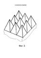
Дополнительно упомянутый рельеф выполнен с образованием рядов четырехугольных пирамид.Additionally, the relief is made with the formation of rows of quadrangular pyramids.
Кроме того, упомянутый рельеф выполнен в виде параллельных щелей.In addition, the aforementioned relief is made in the form of parallel slots.
Дополнительно число магнитов в магнитной системе может быть более одного.Additionally, the number of magnets in the magnetic system may be more than one.
Кроме того, маховик выполнен из ферромагнитного материала.In addition, the flywheel is made of ferromagnetic material.
Дополнительно, зазор между верхним торцом маховика и верхним полюсным наконечником выполнен меньшим зазора между нижним торцом маховика и нижним полюсным наконечником.Additionally, the gap between the upper end of the flywheel and the upper pole tip is made smaller than the gap between the lower end of the flywheel and the lower pole tip.
Кроме того, маховик выполнен из сегнетоэлектрика.In addition, the flywheel is made of ferroelectric.
Дополнительно маховик выполнен из сегнетомагнетика.Additionally, the flywheel is made of ferroelectric.
Сущность изобретения поясняется чертежами, где на фиг. 1 показан вертикальный разрез маховика накопителя энергии и магнитной системы; на фиг. 2 показан маховик накопителя энергии и магнитная система (вид сверху); на фиг. 3 показан фрагмент поверхностей торцов маховика с рельефом, выполненным с образованием рядов четырехугольных пирамид; на фиг. 4 показан фрагмент поверхностей торцов маховика с рельефом, выполненным с образованием параллельных щелей.The invention is illustrated by drawings, where in FIG. 1 shows a vertical section through a flywheel of an energy storage device and a magnetic system; in FIG. 2 shows the flywheel of the energy storage device and the magnetic system (top view); in FIG. 3 shows a fragment of the surfaces of the ends of the flywheel with a relief made with the formation of rows of quadrangular pyramids; in FIG. 4 shows a fragment of the surfaces of the ends of the flywheel with a relief made with the formation of parallel slots.
Для большей наглядности чертежей на них не показаны вакуумируемый корпус и некоторые другие детали, идентичные деталям прототипа.For greater clarity, the drawings do not show the evacuated housing and some other details identical to the details of the prototype.
Накопитель энергии содержит вакуумируемый корпус, закрытый крышкой, маховик 1 в виде вертикального полого цилиндра с установленными внутри маховика на некотором удалении от его торцов перемычками 3 и 4, прикрепленными к оси 2. Маховик 1 упрочнен слоями полимерного материала, например стеклопластика или углепластика. Маховик 1 приводится во вращение мотор-генератором со статором, закрепленным на корпусе, и приводным диском, соединенным с осью 2. В накопителе энергии установлена магнитная система, содержащая магнит 5 и полюсные наконечники 6 и 7, плоскости которых параллельны плоскостям торцов маховика 1, установленные с образованием зазоров между ними и торцами маховика 1. Магнит 5 может быть постоянным, например, с использованием диспрозия, но возможно и применение электромагнита с питанием его от накопителя энергии.The energy storage device contains a vacuum housing closed by a lid, a
В варианте накопителя цилиндрические поверхности маховика 1 выполнены с образованием рельефа.In the embodiment of the drive, the cylindrical surface of the
В варианте накопителя упомянутый рельеф выполнен с образованием рядов четырехугольных пирамид.In a variant of the drive, said relief is formed with the formation of rows of quadrangular pyramids.
Устройство работает следующим образом.The device operates as follows.
Магнит 5 посредством полюсных наконечников 6 и 7 производит в маховике 1 магнитное поле, направленное параллельно оси маховика 1. Под влиянием этого магнитного поля при вращении маховика 1 мотор-генератором в маховике 1 возникает ЭДС, направленная радиально. Под влиянием этой ЭДС на внешней и внутренней цилиндрических поверхностях маховика 1 образуются электрические заряды разных знаков. Вследствие вращения маховика 1 возникают круговые токи на цилиндрических поверхностях маховика 1, также имеющие противоположные направления. Эти токи вызывают магнитное поле в маховике 1, в котором накапливается магнитная энергия. Одновременно накапливается и механическая энергия, обусловленная вращающейся массой маховика 1. При работе мотор-генератора в режиме двигателя вследствие инерции, обусловленной как массой маховика 1, так и энергией магнитного поля, маховик 1 вращает вал за счет накопленной энергии.The
Наличие рельефа на цилиндрических поверхностях увеличивает их поверхность, что способствует увеличению поверхностного заряда и, соответственно, увеличению токов и магнитной энергии. Вид рельефа и число магнитов определяются конкретными условиями технологии производства. При выполнении зазора между верхним торцом маховика 1 и верхним полюсным наконечником меньше зазора между нижним торцом маховика 1 и нижним полюсным наконечником, по крайней мере, часть веса маховика 1 компенсируется, что облегчает работу подшипников. Выполнение маховика 1 из ферромагнитного материала обеспечивает меньшее магнитное сопротивление магнитной цепи, а следовательно, большую магнитную индукцию при той же силе магнита, а также большие ЭДС, заряд и накопленную энергию при той же скорости вращения. Кроме того, высокая относительная магнитная проницаемость ферромагнетиков увеличивает индуктивность маховика 1 и, следовательно, запасенную энергию, при той же силе токе. Применение сегнетоэлектрика в маховике позволяет увеличить поверхностный заряд за счет поляризации материала маховика. Применение сегнетомагнетика позволяет использовать преимущества как ферромагнетика, так и сегнетоэлектрика.The presence of relief on cylindrical surfaces increases their surface, which contributes to an increase in surface charge and, accordingly, an increase in currents and magnetic energy. The type of relief and the number of magnets are determined by the specific conditions of the production technology. When the clearance between the upper end of the
Проведенные расчеты показали, что заявляемое устройство с размерами маховика 200 мм, 433 мм, 233 мм (высота, внешний диаметр, внутренний диаметр), выполненного из легированной стали (относительная магнитная проницаемость 200) при максимально допустимой скорости вращения маховика способно накопить 6⋅106 Дж механической энергии и 20⋅108 Дж магнитной энергии при выполнении по 10000 щелей глубиной 20 мм на каждой из цилиндрических поверхностей маховика.The calculations showed that the inventive device with a flywheel size of 200 mm, 433 mm, 233 mm (height, outer diameter, inner diameter) made of alloy steel (relative magnetic permeability 200) at the maximum permissible speed of rotation of the flywheel can accumulate 6⋅10 6 J of mechanical energy and 20⋅10 8 J of magnetic energy when performing 10,000 slots with a depth of 20 mm on each of the cylindrical surfaces of the flywheel.
Для сравнения: маховик прототипа высотой 400 мм при массе, приблизительно равной массе маховика заявляемого устройства вместе с магнитной системой, согласно тем же расчетам способен накопить 1,2⋅107 Дж механической энергии.For comparison: the flywheel of the prototype with a height of 400 mm with a mass approximately equal to the mass of the flywheel of the inventive device together with the magnetic system, according to the same calculations, is capable of accumulating 1.2 × 10 7 Joules of mechanical energy.
Claims (9)
Priority Applications (1)
| Application Number | Priority Date | Filing Date | Title |
|---|---|---|---|
| RU2015133277A RU2621309C2 (en) | 2015-08-07 | 2015-08-07 | Energy storage unit |
Applications Claiming Priority (1)
| Application Number | Priority Date | Filing Date | Title |
|---|---|---|---|
| RU2015133277A RU2621309C2 (en) | 2015-08-07 | 2015-08-07 | Energy storage unit |
Publications (2)
| Publication Number | Publication Date |
|---|---|
| RU2015133277A RU2015133277A (en) | 2017-02-09 |
| RU2621309C2 true RU2621309C2 (en) | 2017-06-01 |
Family
ID=58453524
Family Applications (1)
| Application Number | Title | Priority Date | Filing Date |
|---|---|---|---|
| RU2015133277A RU2621309C2 (en) | 2015-08-07 | 2015-08-07 | Energy storage unit |
Country Status (1)
| Country | Link |
|---|---|
| RU (1) | RU2621309C2 (en) |
Cited By (2)
| Publication number | Priority date | Publication date | Assignee | Title |
|---|---|---|---|---|
| RU2713385C1 (en) * | 2018-08-02 | 2020-02-05 | Федеральное государственное учреждение "Федеральный научно-исследовательский центр "Кристаллография и фотоника" Российской академии наук" (ФНИЦ "Кристаллография и фотоника" РАН) | Energy accumulator |
| RU2746794C1 (en) * | 2020-10-01 | 2021-04-21 | Сергей Викторович Владимиров | Kinetic energy storage device |
Citations (5)
| Publication number | Priority date | Publication date | Assignee | Title |
|---|---|---|---|---|
| SU178177A1 (en) * | ||||
| SU1534638A1 (en) * | 1986-10-21 | 1990-01-07 | Пермский политехнический институт | Buffer accumulator of kinetic energy |
| EP0821462A2 (en) * | 1994-08-08 | 1998-01-28 | British Nuclear Fuels PLC | An energy storage and conversion apparatus |
| RU2246034C1 (en) * | 2001-01-05 | 2005-02-10 | Сееба-Энергисистеме Гмбх | Flywheel accumulator |
| CN101420150A (en) * | 2008-11-28 | 2009-04-29 | 东南大学 | Energy accumulation device for fly wheel |
-
2015
- 2015-08-07 RU RU2015133277A patent/RU2621309C2/en not_active IP Right Cessation
Patent Citations (5)
| Publication number | Priority date | Publication date | Assignee | Title |
|---|---|---|---|---|
| SU178177A1 (en) * | ||||
| SU1534638A1 (en) * | 1986-10-21 | 1990-01-07 | Пермский политехнический институт | Buffer accumulator of kinetic energy |
| EP0821462A2 (en) * | 1994-08-08 | 1998-01-28 | British Nuclear Fuels PLC | An energy storage and conversion apparatus |
| RU2246034C1 (en) * | 2001-01-05 | 2005-02-10 | Сееба-Энергисистеме Гмбх | Flywheel accumulator |
| CN101420150A (en) * | 2008-11-28 | 2009-04-29 | 东南大学 | Energy accumulation device for fly wheel |
Cited By (2)
| Publication number | Priority date | Publication date | Assignee | Title |
|---|---|---|---|---|
| RU2713385C1 (en) * | 2018-08-02 | 2020-02-05 | Федеральное государственное учреждение "Федеральный научно-исследовательский центр "Кристаллография и фотоника" Российской академии наук" (ФНИЦ "Кристаллография и фотоника" РАН) | Energy accumulator |
| RU2746794C1 (en) * | 2020-10-01 | 2021-04-21 | Сергей Викторович Владимиров | Kinetic energy storage device |
Also Published As
| Publication number | Publication date |
|---|---|
| RU2015133277A (en) | 2017-02-09 |
Similar Documents
| Publication | Publication Date | Title |
|---|---|---|
| KR101173107B1 (en) | Generator | |
| US8461730B2 (en) | Radial flux permanent magnet alternator with dielectric stator block | |
| US10715006B2 (en) | High power flywheel system with rotor having a flowable back iron and a composite structure support | |
| US9647522B2 (en) | Linear induction generator using magnetic repulsion | |
| US10720821B2 (en) | Direct drive generator for renewable energy applications | |
| KR101162477B1 (en) | Power generator having multilayer coil and multilayer permanent magnet | |
| EP2413477A2 (en) | Rotating electrical machine, linear motion electrical machine, and wind generator system | |
| US20100013233A1 (en) | Vertical shaft, horizontally driven, shrouded wind/electric system | |
| US20120206003A1 (en) | Brushless direct current (dc) electric generator with decreased electromagnetic drag | |
| RU2621309C2 (en) | Energy storage unit | |
| US20130154423A1 (en) | Axial flux alternator with one or more flux augmentation rings | |
| US11677295B1 (en) | Mechanical energy and storage device | |
| KR101146717B1 (en) | Permanent Magnet Chain Track type Generator | |
| KR101872262B1 (en) | Magnet generator | |
| Jiang et al. | Design of a novel linear permanent magnet vibration energy harvester | |
| CN103259366B (en) | A kind of wind power generation plant | |
| Sezenoğlu et al. | Design of axial flux permanent magnet generator for generator driven electromagnetic launcher | |
| Torres et al. | Electromagnetic induction generator toward energy harvesting for dynamic systems | |
| Ubani et al. | Analysis of an air-cored axial flux permanent magnet machine with Halbach array | |
| RU2713385C1 (en) | Energy accumulator | |
| KR101818297B1 (en) | Rotating Armature Type Wind Power Generator with Dual Field Windings | |
| RU2366829C1 (en) | Birotary windmill | |
| Zhu et al. | Comparisons of electromagnetic transducers for rotational energy harvesting | |
| CN106300876B (en) | A kind of Electromagnetic Control screw rod accelerator | |
| RU71189U1 (en) | LOW-TURNING ELECTRIC MACHINE |
Legal Events
| Date | Code | Title | Description |
|---|---|---|---|
| MM4A | The patent is invalid due to non-payment of fees |
Effective date: 20200808 |