RU2621190C2 - Method and system of emergency starting energy generation setting - Google Patents
Method and system of emergency starting energy generation setting Download PDFInfo
- Publication number
- RU2621190C2 RU2621190C2 RU2014142446A RU2014142446A RU2621190C2 RU 2621190 C2 RU2621190 C2 RU 2621190C2 RU 2014142446 A RU2014142446 A RU 2014142446A RU 2014142446 A RU2014142446 A RU 2014142446A RU 2621190 C2 RU2621190 C2 RU 2621190C2
- Authority
- RU
- Russia
- Prior art keywords
- engine
- shaft
- installation
- emergency start
- gases
- Prior art date
Links
Images
Classifications
-
- F—MECHANICAL ENGINEERING; LIGHTING; HEATING; WEAPONS; BLASTING
- F02—COMBUSTION ENGINES; HOT-GAS OR COMBUSTION-PRODUCT ENGINE PLANTS
- F02C—GAS-TURBINE PLANTS; AIR INTAKES FOR JET-PROPULSION PLANTS; CONTROLLING FUEL SUPPLY IN AIR-BREATHING JET-PROPULSION PLANTS
- F02C7/00—Features, components parts, details or accessories, not provided for in, or of interest apart form groups F02C1/00 - F02C6/00; Air intakes for jet-propulsion plants
- F02C7/26—Starting; Ignition
- F02C7/268—Starting drives for the rotor, acting directly on the rotor of the gas turbine to be started
- F02C7/27—Fluid drives
- F02C7/272—Fluid drives generated by cartridges
-
- F—MECHANICAL ENGINEERING; LIGHTING; HEATING; WEAPONS; BLASTING
- F02—COMBUSTION ENGINES; HOT-GAS OR COMBUSTION-PRODUCT ENGINE PLANTS
- F02C—GAS-TURBINE PLANTS; AIR INTAKES FOR JET-PROPULSION PLANTS; CONTROLLING FUEL SUPPLY IN AIR-BREATHING JET-PROPULSION PLANTS
- F02C7/00—Features, components parts, details or accessories, not provided for in, or of interest apart form groups F02C1/00 - F02C6/00; Air intakes for jet-propulsion plants
- F02C7/26—Starting; Ignition
- F02C7/268—Starting drives for the rotor, acting directly on the rotor of the gas turbine to be started
- F02C7/275—Mechanical drives
-
- F—MECHANICAL ENGINEERING; LIGHTING; HEATING; WEAPONS; BLASTING
- F02—COMBUSTION ENGINES; HOT-GAS OR COMBUSTION-PRODUCT ENGINE PLANTS
- F02N—STARTING OF COMBUSTION ENGINES; STARTING AIDS FOR SUCH ENGINES, NOT OTHERWISE PROVIDED FOR
- F02N13/00—Starting of engines, or driving of starting apparatus by use of explosives, e.g. stored in cartridges
-
- F—MECHANICAL ENGINEERING; LIGHTING; HEATING; WEAPONS; BLASTING
- F02—COMBUSTION ENGINES; HOT-GAS OR COMBUSTION-PRODUCT ENGINE PLANTS
- F02N—STARTING OF COMBUSTION ENGINES; STARTING AIDS FOR SUCH ENGINES, NOT OTHERWISE PROVIDED FOR
- F02N15/00—Other power-operated starting apparatus; Component parts, details, or accessories, not provided for in, or of interest apart from groups F02N5/00 - F02N13/00
- F02N15/10—Safety devices not otherwise provided for
-
- Y—GENERAL TAGGING OF NEW TECHNOLOGICAL DEVELOPMENTS; GENERAL TAGGING OF CROSS-SECTIONAL TECHNOLOGIES SPANNING OVER SEVERAL SECTIONS OF THE IPC; TECHNICAL SUBJECTS COVERED BY FORMER USPC CROSS-REFERENCE ART COLLECTIONS [XRACs] AND DIGESTS
- Y02—TECHNOLOGIES OR APPLICATIONS FOR MITIGATION OR ADAPTATION AGAINST CLIMATE CHANGE
- Y02T—CLIMATE CHANGE MITIGATION TECHNOLOGIES RELATED TO TRANSPORTATION
- Y02T50/00—Aeronautics or air transport
- Y02T50/60—Efficient propulsion technologies, e.g. for aircraft
Abstract
Description
ОБЛАСТЬ ТЕХНИКИFIELD OF TECHNOLOGY
Изобретение касается способа и системы экстренного запуска установки генерирования энергии в критических ситуациях, когда специальные приводные средства остановлены или их недостаточно для решения проблемы.The invention relates to a method and system for urgently starting an energy generation installation in critical situations, when special drive means are stopped or they are insufficient to solve the problem.
Изобретение находит свое применение в рамках содействия или крайних мер для включения активации или повторной активации генерирования энергии в различных областях техники:The invention finds its application in the framework of assistance or extreme measures to include the activation or reactivation of energy generation in various fields of technology:
- в области авиационных силовых установок для газовых турбин самолета или вертолета;- in the field of aircraft power plants for gas turbines of an airplane or helicopter;
- в области электротехники для аварийных ограничительных выключателей в инфраструктурах производства и передачи электрической энергии, в частности на подводных лодках;- in the field of electrical engineering for emergency limit switches in infrastructures for the production and transmission of electrical energy, in particular in submarines;
- в области подземного или подводного бурения для приводов фонтанных задвижек, роботов и т.д.; эта область называется нефтегазодобывающей;- in the field of underground or underwater drilling for actuators of fountain valves, robots, etc .; this area is called oil and gas;
- в экстремальных средах (больницы, атомные электростанции, аэропорты, серверные центры) для генераторов, насосов, защитных клапанов и т.д.;- in extreme environments (hospitals, nuclear power plants, airports, server centers) for generators, pumps, safety valves, etc .;
- в области термодинамики для генерирующих установок типа Стерлинга или Эриксона;- in the field of thermodynamics for generating installations such as Stirling or Erickson;
- в области гидравлики или пневматики для манипулирования массами (силовые цилиндры взлетно-посадочных шасси, подъемные устройства и т.д.).- in the field of hydraulics or pneumatics for manipulating weights (power cylinders of the landing gear, lifting devices, etc.).
В случае двухмоторного вертолета критические ситуации могут возникнуть, когда один из двигателей был намеренно выключен. Действительно, этот режим рекомендован для минимизации расхода топлива во время фаз поиска и полета на крейсерской скорости при выполнении задачи. В этом контексте могут возникнуть две исключительные ситуации, которые требует экстренного повторного запуска выключенного двигателя:In the case of a twin-engine helicopter, critical situations may arise when one of the engines was intentionally turned off. Indeed, this mode is recommended to minimize fuel consumption during the search and flight phases at cruising speed when performing a task. In this context, two exceptional situations may arise that require an emergency restart of the engine off:
- единственный активный двигатель останавливается или значительно сбавляет обороты по неизвестной причине;- the only active engine stops or significantly slows down for an unknown reason;
- условия полета внезапно ухудшаются, что требует возврата к режиму полета на двух двигателях (например, недостаточная высота полета).- flight conditions suddenly deteriorate, which requires a return to flight mode on two engines (for example, insufficient flight altitude).
УРОВЕНЬ ТЕХНИКИBACKGROUND
В настоящее время повторный запуск газовой турбины можно осуществлять с использованием трех типов стартеров, различающихся по своей физической сущности:Currently, a gas turbine can be restarted using three types of starters, which differ in their physical nature:
- электрические стартеры, питаемые от бортовой сети или от батареи;- electric starters powered by the on-board network or from the battery;
- пневматические стартеры, содержащие устройство преобразования крутящего момента (эпициклоидная передача или многоступенчатая зубчатая передача) и резервуар газа под давлением; и- pneumatic starters containing a torque conversion device (epicycloid gear or multistage gear) and a gas reservoir under pressure; and
- гидравлические стартеры, состоящие из генератора текучей среды под давлением, связанного с резервуаром текучей среды под давлением.- hydraulic starters, consisting of a pressurized fluid generator coupled to a pressurized fluid reservoir.
Пневматические и гидравлические стартеры имеют недостатки, связанные с их массой и габаритами. Кроме того, они требуют периодического контроля кожухов и замены резервуаров под давлением.Pneumatic and hydraulic starters have drawbacks related to their weight and dimensions. In addition, they require periodic inspection of covers and replacement of pressure tanks.
Поэтому для применения на вертолете в случае вышеупомянутой экстренной ситуации повторный запуск газотурбинного двигателя осуществляют при помощи электрического стартера, питаемого от бортовой сети или от резервной батареи. Однако эта технология является дорогостоящей: присутствие постоянных магнитов, поперечного потока, планарной архитектуры и т.д. Кроме того, она требует наличия электронного устройства контроля нагрузки и периодической замены батареи.Therefore, for use in a helicopter in the case of the aforementioned emergency, the gas turbine engine is restarted using an electric starter powered by an on-board network or a backup battery. However, this technology is expensive: the presence of permanent magnets, transverse flux, planar architecture, etc. In addition, it requires an electronic load monitoring device and periodic battery replacement.
Кроме того, эти электрические стартеры не производят моментального крутящего момента. Время реакции обычно составляет около тридцати секунд для повторного запуска двигателя в режиме ожидания, что может оказаться слишком долго в зависимости от условий полета, например, на низкой высоте при, по меньшей мере, частичной неисправности единственного активного двигателя. Если двигатель в режиме ожидания не удается вовремя запустить повторно, посадка с проблемой в двигателе может оказаться критической.In addition, these electric starters do not produce instantaneous torque. The reaction time is usually about thirty seconds to restart the engine in standby mode, which may be too long depending on the flight conditions, for example, at low altitude with at least partial malfunction of the only active engine. If the engine in standby mode cannot be restarted in time, landing with a problem in the engine may be critical.
Как правило, аварийные ситуации, которые могут возникать в вышеупомянутых вариантах применения, требуют времени реакции порядка нескольких секунд, в частности двух-трех секунд и даже одной секунды, чтобы обеспечивать экстренный запуск или повторный запуск с достаточным запасом надежности.Typically, emergencies that may occur in the aforementioned applications require a reaction time of the order of several seconds, in particular two to three seconds and even one second, to provide an emergency start or restart with a sufficient safety margin.
СУЩНОСТЬ ИЗОБРЕТЕНИЯSUMMARY OF THE INVENTION
Изобретение касается аварийных стартеров, обеспечивающих реакцию указанного порядка величины, то есть в несколько секунд, и не имеющих недостатков, связанных с массой и с габаритами вышеупомянутых гидравлических или пневматических аварийных стартеров.The invention relates to emergency starters, providing a reaction of the indicated order of magnitude, that is, in a few seconds, and without the disadvantages associated with the mass and dimensions of the aforementioned hydraulic or pneumatic emergency starters.
Для этого настоящим изобретением предлагается объединить моментальное толкающее усилие газа, типа пиротехнического, с трансмиссионным объемным генератором в сочетании с автоматическим соединением/разъединением с запускаемой установкой.To this end, the present invention proposes to combine the instantaneous pushing force of a gas, such as pyrotechnic, with a volumetric transmission generator in combination with automatic connection / disconnection with the installation being started.
В частности, объектом настоящего изобретения является способ экстренного запуска установки генерирования энергии, в котором при обнаружении ситуации необходимости экстренного запуска установки включают, по меньшей мере, один пиротехнический генератор сжигания газов. Посредством этого сжигания генерируют газы под давлением, которые напрямую нагнетают в объемный двигатель с зубчатыми передачами, предпочтительно прямозубыми. Часть этих газов приводит во вращение зубчатые передачи двигателя, и одновременно часть оставшихся газов толкает, против возвратной силы, систему соединения между двигателем и установкой. Система соединения обеспечивает передачу энергии посредством приведения во вращение вала зубчатой передачи объемного двигателя на приемном валу установки. Когда толкающее усилие становится меньше возвратной силы, последняя автоматически отталкивает систему соединения, и установка отсоединяется от объемного двигателя.In particular, an object of the present invention is to provide an emergency start-up method for an energy generating installation, in which upon detection of a need for urgent start-up of the installation, at least one pyrotechnic gas burning generator is included. Through this combustion, pressurized gases are generated which are directly injected into the volumetric engine with gears, preferably spur gears. Part of these gases drives the gears of the engine, and at the same time, part of the remaining gases pushes against the return force the connection system between the engine and the installation. The coupling system provides energy transfer by driving the gear shaft of the volumetric engine on the receiving shaft of the installation. When the pushing force becomes less than the return force, the latter automatically repels the connection system, and the installation is disconnected from the surround engine.
Согласно частным вариантам осуществления:According to private options for implementation:
- система соединения между валом зубчатой передачи и приемным валом запускаемой установки осуществляют трением;- the connection system between the gear shaft and the receiving shaft of the starting installation is carried out by friction;
- оставшиеся газы нагнетают в объемный двигатель по периферии вокруг продольной оси таким образом, что за счет радиального сжатия система соединения вызывает приведение во вращение вала запускаемой установки;- the remaining gases are pumped into the volumetric engine on the periphery around the longitudinal axis in such a way that due to the radial compression, the connection system causes the shaft of the launched installation to rotate;
- оставшиеся газы нагнетают в объемный двигатель по центру вдоль продольной оси таким образом, что посредством конусного зацепления система соединения вызывает приведение во вращение вала запускаемой установки за счет осевого и радиального сжатия;- the remaining gases are pumped into the volumetric engine in the center along the longitudinal axis in such a way that by means of cone engagement the connection system causes the shaft of the launched installation to rotate due to axial and radial compression;
- последовательно включают генерирования сжигания пиротехнических газов;- consistently include the generation of pyrotechnic gas combustion;
- возвратную силу создают средства, выбираемые из: упругой силы, электромагнитной силы и расширения сжатой текучей среды.- the return force is created by means selected from: elastic force, electromagnetic force, and expansion of the compressed fluid.
Объектом изобретения является также система экстренного запуска установки генерирования энергии, выполненная с возможностью осуществления вышеуказанного способа. Эта система содержит, по меньшей мере, один пиротехнический газогенератор, связанный с электрическим инициатором, который, в свою очередь, связан с вычислительным устройством, объемный двигатель, содержащий корпус, определяющий внутреннее пространство, в котором находятся прямозубые зубчатые передачи, при этом пиротехнический газогенератор связан с двигателем через вход корпуса. Двигатель содержит средство соединения, выполненное с возможностью перемещения на конце трансмиссионного вала, центрованного по оси зубчатой передачи объемного двигателя, и предназначенное для соединения этого трансмиссионного вала с приемным валом установки через центробежное сцепление, и возвратное средство, выполненное в виде упора, выполнено с возможностью действия возвратной силой против давления, действующего на средство соединения.An object of the invention is also an emergency start-up system for a power generation installation, configured to implement the above method. This system contains at least one pyrotechnic gas generator associated with an electric initiator, which, in turn, is connected to a computing device, a volume engine containing a housing defining an internal space in which spur gears are located, wherein the pyrotechnic gas generator is connected with an engine through the input of the housing. The engine comprises coupling means arranged to move at the end of the transmission shaft centered on the gear axis of the volumetric engine and intended to connect this transmission shaft to the receiving shaft of the installation through a centrifugal clutch, and the return means made in the form of a stop is made with the possibility of action back force against the pressure acting on the connection means.
Как правило, размеры каждого объемного двигателя определяют таким образом, чтобы он развивал мощность порядка 40 кВт в течение примерно 2,5 секунд при каждом нагнетании пиротехнического газа с временем реакции порядка 0,5 секунды. Кроме того, система рассчитана и сертифицирована для обеспечения номинального использования в температурном диапазоне от -30°С до +50°С, который может быть расширен до предельных квалификационных температур окружающего оборудования, например, порядка 135°С для вышеупомянутых экстремальных сред. Окружающее давление использования составляет примерно от 60 кПа до 110 кПа.As a rule, the dimensions of each volumetric engine are determined so that it develops power of the order of 40 kW for about 2.5 seconds with each injection of pyrotechnic gas with a reaction time of about 0.5 seconds. In addition, the system is designed and certified to ensure nominal use in the temperature range from -30 ° C to + 50 ° C, which can be expanded to the maximum qualification temperatures of the surrounding equipment, for example, about 135 ° C for the above-mentioned extreme environments. The use ambient pressure is from about 60 kPa to 110 kPa.
Согласно предпочтительным вариантам выполнения:According to preferred embodiments:
- кольцевое пространство, образованное в продолжении корпуса на периферии трансмиссионного вала объемного двигателя, сообщается с упомянутым внутренним пространством для обеспечения нагнетания части газов, образующихся при сжигании пиротехнического газа, до средства соединения; при этом упомянутое средство соединения состоит из кольцевого поршня, выполненного с возможностью поступательного перемещения под действием толкающего усилия газов вдоль трансмиссионного вала двигателя с целью воздействия давлением на муфту, выполненную с возможностью раздвигаться под действием этого давления и приведения в действие центробежного сцепления посредством трения;- the annular space formed in the continuation of the housing on the periphery of the transmission shaft of the volumetric engine is in communication with the said inner space to ensure the injection of part of the gases generated during the combustion of pyrotechnic gas to the connection means; wherein said coupling means consists of an annular piston arranged for translational movement under the action of a pushing force of gases along the engine transmission shaft in order to exert pressure on the coupling configured to move apart under the influence of this pressure and actuate the centrifugal clutch by friction;
- второй элемент соединения состоит, по меньшей мере, из одного открытого кольцевого участка муфты, радиальное раздвигание которого осуществляется скольжением вдоль конусного участка трансмиссионного вала двигателя;- the second connection element consists of at least one open annular section of the coupling, the radial extension of which is carried out by sliding along the conical section of the transmission shaft of the engine;
- канал, связанный с входом газов корпуса, сообщается с центральным отверстием трансмиссионного вала для обеспечения циркуляции части газов, поступающих из пиротехнического газогенератора, до средства соединения; при этом упомянутое средство соединения состоит из конусного поршня, выполненного с возможностью поступательного перемещения под действием толкающего усилия газов по оси трансмиссионного вала двигателя с целью захождения в конусное отверстие, выполненное в центробежном сцеплении, для его приведения в действие посредством трения;- the channel associated with the gas inlet of the housing communicates with the Central hole of the transmission shaft to circulate part of the gases coming from the pyrotechnic gas generator to the connection means; wherein said connecting means consists of a conical piston adapted to translate under the action of a pushing force of gases along the axis of the transmission shaft of the engine to enter a conical hole made in a centrifugal clutch to actuate it by friction;
- электрический инициатор состоит из электронного блока, содержащего автономный электрический источник энергии, и электронной карты управления, включающей в себя термочувствительный компонент и микроконтроллер управления электрическим источником, термочувствительным компонентом, функциональными автотестами, а также сигналами срабатывания запального патрона пиротехнического газогенератора;- the electric initiator consists of an electronic unit containing an autonomous electrical energy source, and an electronic control card, including a thermosensitive component and a microcontroller for controlling an electric source, a thermosensitive component, functional autotests, as well as the operation signals of the ignition cartridge of a pyrotechnic gas generator;
- зубчатые передачи объемного двигателя представляют собой прямозубые зубчатые передачи;- gears of a volumetric engine are spur gears;
- объемный двигатель является двухступенчатым, при этом первая ступень связана на выходе со второй ступенью, установленной в виде тандема, при этом первый двигатель является двигателем с прямозубыми зубчатыми колесами или пластинчатым двигателем, при этом выход газов первого двигателя соединен с входом газов второго двигателя, который может иметь размер, по существу превышающий размер первого двигателя, при этом центральный или трансмиссионный вал первого двигателя установлен на вторичном валу второго двигателя;- the volumetric engine is two-stage, with the first stage connected at the output to the second stage installed in the form of a tandem, the first engine being an engine with spur gears or a plate engine, while the gas outlet of the first engine is connected to the gas inlet of the second engine, which may have a size substantially larger than the size of the first engine, with the central or transmission shaft of the first engine mounted on the secondary shaft of the second engine;
- в случае когда установка является турбомашиной, содержащей вал каскада высокого давления или ВД, приемный вал выбран из: вала коробки агрегатов, установленной на каскаде ВД, кожуха, неподвижно соединенного с зубчатым колесом коробки агрегатов и используемого в качестве центробежного сцепления, и вала каскада ВД;- in the case when the installation is a turbomachine containing a shaft of a high-pressure cascade or a VD, the receiving shaft is selected from: a shaft of an aggregate box mounted on the VD cascade, a casing fixedly connected to the gear wheel of the aggregate box and used as a centrifugal clutch, and a VD cascade shaft ;
- в случае когда установка является аварийным ограничительным выключателем, приемный вал является валом полюсов, освобождаемым при коротком замыкании;- in the case when the installation is an emergency limit switch, the receiving shaft is the shaft of the poles, released during a short circuit;
- в области нефтегазодобывающей промышленности или в экстремальных средах приемный вал является валом механического приводного инструмента (вентиль, зубчатая рейка, робот, насос, решетка замедлителей);- in the oil and gas industry or in extreme environments, the receiving shaft is the shaft of a mechanical power tool (valve, gear rack, robot, pump, retarder grill);
- в случае установки типа термодинамического двигателя с циклом Стерлинга, или Эриксона, или эквивалентного типа, содержащей теплообменник и схему с регулируемым углом установки, приемный вал является валом привода теплообменника, и электронный блок включает в себя дополнительную функцию регулировки соответствующего угла установки во время изохорных фаз нагрева и конденсации цикла термодинамического двигателя.- in the case of installing a type of thermodynamic engine with a Sterling cycle, or Erickson, or an equivalent type containing a heat exchanger and a circuit with an adjustable installation angle, the receiving shaft is the drive shaft of the heat exchanger, and the electronic unit includes an additional function to adjust the corresponding installation angle during isochoric phases heating and condensing cycle of a thermodynamic engine.
КРАТКОЕ ОПИСАНИЕ ЧЕРТЕЖЕЙBRIEF DESCRIPTION OF THE DRAWINGS
Другие аспекты, отличительные признаки и преимущества изобретения будут более очевидны из нижеследующего описания частных вариантов выполнения со ссылками на прилагаемые чертежи, на которых:Other aspects, features and advantages of the invention will be more apparent from the following description of particular embodiments with reference to the accompanying drawings, in which:
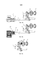
Фиг. 1 - схематичный вид в поперечном разрезе первого примера объемного двигателя системы экстренного запуска в соответствии с изобретением.FIG. 1 is a schematic cross-sectional view of a first example of a surround engine of an emergency start system in accordance with the invention.
Фиг. 2а и 2b - схематичный вид в продольном разрезе объемного двигателя, показанного на Фиг.1, до и после выброса пиротехнического газа.FIG. 2a and 2b are a schematic longitudinal sectional view of the volumetric engine shown in FIG. 1 before and after the release of pyrotechnic gas.
Фиг. 3а-3с - вид в перспективе, в поперечном разрезе по плоскости ВВ и в продольном разрезе по плоскости СС другого примера объемного двигателя системы экстренного запуска в соответствии с изобретением.FIG. 3a-3c is a perspective view, in transverse section along the plane BB and in longitudinal section along the plane CC, of another example of a three-dimensional engine of the emergency launch system in accordance with the invention.
Фиг. 4 - общий вид примера системы экстренного запуска в соответствии с изобретением, состоящей из электронного блока, пиротехнического генератора и объемного двигателя.FIG. 4 is a general view of an example of an emergency start system in accordance with the invention, consisting of an electronic unit, a pyrotechnic generator, and a three-dimensional engine.
Фиг. 5 - вид в разрезе электронного блока, показанного на Фиг. 4.FIG. 5 is a sectional view of the electronic unit shown in FIG. four.
Фиг. 6 - вид в разрезе пиротехнического генератора, показанного на Фиг. 4.FIG. 6 is a sectional view of the pyrotechnic generator shown in FIG. four.
Фиг. 7а - вид в разрезе двухступенчатого объемного двигателя, содержащего два двигателя с прямозубыми зубчатыми колесами.FIG. 7a is a sectional view of a two-stage displacement engine comprising two engines with spur gears.
Фиг. 7b - вид в разрезе двухступенчатого объемного двигателя, содержащего роликовый двигатель, связанный с двигателем с прямозубыми зубчатыми колесами.FIG. 7b is a sectional view of a two-stage displacement engine comprising a roller engine coupled to a spur gear motor.
Фиг. 8а - пример монтажа объемного двигателя системы запуска в соответствии с изобретением на валу коробки агрегатов турбомашины.FIG. 8a is an example of mounting a displacement engine of a start-up system in accordance with the invention on a shaft of a box of turbomachine units.
Фиг. 8b - монтаж этого объемного двигателя на кожухе, жестко соединенном с зубчатым колесом коробки агрегатов, показанной на Фиг. 8а.FIG. 8b is a mounting of this three-dimensional engine on a casing rigidly connected to the gear wheel of the assembly box shown in FIG. 8a.
Фиг. 8с - монтаж этого объемного двигателя непосредственно на валу каскада ВД турбомашины, показанного на Фиг. 8а.FIG. 8c shows the installation of this three-dimensional engine directly on the shaft of the VD cascade of the turbomachine shown in FIG. 8a.
ПОДРОБНОЕ ОПИСАНИЕDETAILED DESCRIPTION
В настоящем описании выражение «поперечный разрез» относится к проекции в плоскости, перпендикулярной к продольной оси двигателей, которые в основном расположены вдоль такой оси. Выражение «продольный разрез» обозначает вид в разрезе вдоль упомянутой продольной оси. Определения «верхний» или «нижний» относятся к соответствующим местам стенки или стороны устройства, находящегося в стандартном положении использования. Кроме того, идентичные элементы, описанные в соответствующих разделах, обозначены одинаковыми позициями.In the present description, the expression "transverse section" refers to a projection in a plane perpendicular to the longitudinal axis of the engines, which are mainly located along such an axis. The expression “longitudinal section” means a sectional view along said longitudinal axis. The definitions of “top” or “bottom” refer to the corresponding places on the wall or side of a device in its standard position of use. In addition, identical elements described in the corresponding sections are denoted by the same reference numerals.
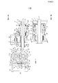
Как показано в поперечном разрезе на Фиг. 1, первый пример объемного двигателя 1 системы экстренного запуска в соответствии с изобретением содержит корпус 2, определяющий внутреннее пространство Е1, в котором находятся два прямозубых зубчатых колеса 3а и 3b, выполненных с возможностью вращения в противоположных направлениях (стрелки Ra и Rb) вокруг трансмиссионных валов 4а и 4b. Корпус 2 имеет две противоположные боковые стенки 2L и 2Lʹ, по существу симметричные относительно продольной плоскости II-II. Вход 21 газов и выход 22 газов, выполненные соответственно на стенках 2L и 2Lʹ, имеют одну и ту же ось А2, которая проходит по существу перпендикулярно к стенкам 2L и 2Lʹ посередине между зубчатыми передачами 3а и 3b.As shown in cross section in FIG. 1, a first example of a
В газовом входе 21 и в центре пиротехнического газогенератора 5 закреплен соединительный канал 2С для обеспечения выталкивания газов сгорания в двигатель 1. Этот газогенератор 5 содержит проперголевый блок 51, соединенный с запальным патроном 52.In the
Как показано на Фиг. 2 в продольном разрезе по плоскости II-II, корпус 2 двигателя 1 и вал 4b зубчатого колеса 3b продолжают друг друга в продольном направлении вдоль трансмиссионного вала 4b с осью зубчатой передачи XʹX для размещения вала 6 запускаемой установки генерирования энергии. Приемный вал 6 проходит через трансмиссионный вал 4b и соединяется за пределами вала 4b с центробежным цилиндрическим сцеплением 7.As shown in FIG. 2 in longitudinal section along plane II-II, the
В центробежном сцеплении 7 заключены подвижные кольцевые детали, - поршень 8а, муфта 8b и опора 8с, - для соединения во вращении между трансмиссионным валом 4b и сцеплением 7. Трансмиссионный вал 4b установлен на опорных подшипниках Р1 и Р2 в цилиндрических удлинениях 20а и 20b корпуса 2, а вал 4а зубчатого колеса 3а установлен в корпусе 2 при помощи механизма 40 с шариками и упругими пластинками.In the centrifugal clutch 7, movable annular parts are enclosed, a
На конце трансмиссионный вал 4b имеет конусный участок 41, на который опирается муфта 8b соответствующей ему усеченной конусной формы. Пружина 9, расположенная в пространстве, закрываемом сцеплением 7, между упором 8с и муфтой 8b, опирается одним концом на муфту 8b и другим концом на фланец 41F, выполненный на конце конусного участка 41.At the end, the
Кроме того, кольцевое пространство Е2, образованное в удлинении 20а корпуса 2 на периферии трансмиссионного вала 8b, сообщается на одном конце с внутренним пространством Е1 двигателя 1 и на другом конце с радиальным пространством Е3, закрытым боковой стороной 8F поршня 8а.In addition, the annular space E2 formed in the
Как показано на Фиг. 2b, когда газы, получаемые при горении проперголя, выталкиваются во внутреннее пространство Е1 (Фиг. 1) двигателя 1, часть этих газов нагнетается в кольцевое пространство Е2 до радиального пространства Е3. Под действием толкающего усилия газов на боковую сторону 8F, поршень 8а приводится в поступательное движение (стрелки F1) по оси X’X вдоль вала 4b, и действует соответствующим давлением на муфту 8b. Муфта 8b, состоящая из двух полумуфт, удерживаемых между поршнем 8а и опорой 8с, раздвигается в радиальном направлении (стрелки F2) посредством скольжения полумуфт вдоль конусного участка 41 и входит в плотный контакт с центробежным сцеплением 7. Сцепление приводится во вращение за счет трения и одновременно приводит во вращение приемный вал 6 запускаемой установки.As shown in FIG. 2b, when the gases produced by the combustion of the propergol are pushed into the inner space E1 (Fig. 1) of the
Как только давление газов падает ниже определенного порога, возвратная пружина 9 действует силой, достаточной для отталкивания муфты 8b в направлении, противоположном стрелке F1, и контакт этой муфты со сцеплением 7 прерывается: приемный вал 6 моментально отсоединяется.As soon as the gas pressure drops below a certain threshold, the
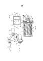
Другой пример объемного двигателя установки экстренного запуска в соответствии с изобретением показан в перспективе и в разрезе на Фиг. 3а-3с.Another example of a surround engine of an emergency start installation in accordance with the invention is shown in perspective and in section in FIG. 3a-3c.
Как показано на Фиг. 3а, объемный двигатель 100 снаружи выглядит, как и предыдущий двигатель, с корпусом 120, содержащим две боковые стенки 20L и 20Lʹ, и с центробежным сцеплением 170, установленным на цилиндрическом удлинении 120а корпуса вокруг трансмиссионного вала (см. Фиг. 3с). Для крепления двигателя на корпусе запускаемой установки на этом цилиндрическом удлинении 120а при помощи кольца 12В установлен фланец 130. На так называемой верхней стенке 12S корпуса 120 находится вход 121 газов.As shown in FIG. 3a, the
Как показано в поперечном разрезе на Фиг. 3b (разрез по плоскости ВВ Фиг. 3а), корпус 120 определяет внутреннее пространство Е11, в котором внутри рубашек 124 находятся два прямозубых зубчатых колеса 3а и 3b из предыдущего примера, выполненные с возможностью вращения в противоположных направлениях (стрелки Ra и Rb) вокруг трансмиссионных валов 40а и 40b. Входящие газы (стрелки F8) разделяются дефлектором 125, а рубашки имеют отверстия 126 для прохождения газов во внутреннее пространство Е11. Трансмиссионный вал 40b содержит центральное отверстие 4А, выполненное с возможностью пропускания части газов сгорания. Две противоположные боковые стенки 20L и 20Lʹ корпуса 120 являются по существу симметричными. Вход 121 газов и выход 122 газов, соответственно выполненные в верхней и нижней стенках, соответственно 12S и 12I, имеют одну и ту же ось симметрии А2, которая проходит в медианной плоскости Pm параллельно стенкам 20L и 20Lʹ. Удаление газов происходит (стрелка F10) через отверстия 126.As shown in cross section in FIG. 3b (section along the plane BB of FIG. 3a), the
На Фиг. 3с (в продольном разрезе по плоскости СС Фиг. 3а) видно, что средство соединения во вращении между трансмиссионным валом 40b, установленным на опорных подшипниках Р3 и Р4, и центробежным сцеплением 170, образовано конусным поршнем 18 и соответствующим конусным гнездом 18L, выполненным в кольцевой детали 19, жестко соединенной с центробежным сцеплением 170. Геликоидальная пружина 90 находится в отверстии 180 поршня 18 вдоль стержня 41, идущего от упора 43, жестко соединенного с концом трансмиссионного вала 40b. Пружина 90 расположена между упором 43 и заплечиком 181, образованным в дне отверстия 180 поршня 18. Кроме того, канал 140, имеющий продольный участок 14L и радиальный участок 14R, соединяет вход 121 газов корпуса 120 с центральным отверстием 4А трансмиссионного вала 40b.In FIG. 3c (in a longitudinal section along the plane CC of Fig. 3a), it is seen that the rotational connection between the
Когда при горении проперголевого газа высвобождаются газообразные продукты горения, основная часть газов приводит во вращение зубчатые колеса 3а и 3b двигателя 100 и валы 4а и 4b. В свою очередь, трансмиссионный вал 4b приводит в действие поршень 18. Меньшая часть газов отбирается в канал 140 (стрелки F3, F4 и F5) и направляется в центральное отверстие 4А вала 40b. Газы выбрасываются при этом на радиальную сторону 18R поршня 18 (стрелка F6), которая поступательно перемещается вдоль оси X’X трансмиссионного вала 40b. Поршень 18 входит в плотный контакт с конусным гнездом 18L и за счет трения приводит во вращение кольцевую деталь 19, а также центробежное сцепление 170, жестко соединенное с деталью 19.When gaseous products of combustion are released during the combustion of the pro-goal gas, the main part of the gases drives the
Как и в предыдущем примере, как только давление газов падает ниже определенного порога, возвратная пружина 90 действует силой, достаточной для отталкивания поршня 18 в направлении, противоположном стрелке F6, и контакт поршня с деталью 19, жестко соединенной со сцеплением 170, прерывается: приемный вал запускаемой установки, связанный со сцеплением 170, отсоединяется.As in the previous example, as soon as the gas pressure drops below a certain threshold, the
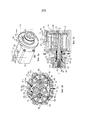
На Фиг. 4 показан общий вид системы 10 экстренного запуска в соответствии с изобретением. Эта система содержит электронный блок 3, пиротехнический генератор 5 и объемный двигатель 100. В частности, электронный блок 3 связан через электрический канал 11 с запальным патроном 52 пиротехнического генератора 5, который, в свою очередь, соединен с входом 121 двигателя 100 через жесткий металлический канал 12. Кроме того, электронный блок 3 связан с вычислительным устройством (не показано) запускаемой установки, в данном примере турбомашины, через электрический канал 13. Соединители 14, закрепленные при помощи винтов 15, обеспечивают соединение каналов 11-13 с электронным блоком 3, с пиротехническим генератором 5 и с объемным двигателем 100. Этот двигатель 100 содержит центробежное сцепление 170, связанное с трансмиссионным валом 40b для приведения во вращение вала запускаемой установки.In FIG. 4 shows a general view of an emergency start system 10 in accordance with the invention. This system comprises an
Как показано в разрезе на Фиг. 5, в электронном блоке 3 расположены батарея 31, представляющая собой автономный электрический источник энергии, и электронная карта 32 управления. Эта карта включает в себя термочувствительный компонент 33 и микроконтроллер 34 управления батареей 31, термочувствительным компонентом 33 и функциональными автотестами, а также сигналами срабатывания запального патрона 52 пиротехнического генератора 5. Проводники 11 и 13 соединены с блоком 3 при помощи соединителей 14.As shown in section in FIG. 5, a
Сигналы срабатывания включают в себя сигналы об обнаружении потенциального пожара, включаемые термочувствительным компонентом 33, и сигналы, управляемые вычислительным устройством в зависимости от данных, поступающих от датчиков скорости или от температурных датчиков.The triggering signals include potential fire detection signals activated by the temperature-
Предпочтительно электронная карта 32 содержит компонент 35 измерения температуры, управляемый микроконтроллером 34, чтобы отслеживать высокие значения температуры и позволять вычислительному устройству устанавливать срок службы без снижения безопасности работы.Preferably, the electronic card 32 comprises a temperature measuring component 35 controlled by the
Кроме того, на Фиг. 6 в разрезе показан пиротехнический генератор 5. Этот генератор содержит металлический корпус 53, в котором на вставках 54 находится проперголевый блок 51. Блок 51 окружен сбоку слоем замедлителя 55. На корпусе 53 жестко закреплен металлический кожух 56 для обеспечения герметичного закрывания. Запальный патрон 52 завинчен в канал 57, образованный в кожухе 56 и закрытый наконечником 57а, выполненным с возможностью расплавления при температуре сверх заранее установленного порога. Газообразные продукты сгорания проперголя, поджигаемого патроном 52, выходят через заслонку 58а регулируемого сопла 58, связанного с металлическим каналом 12, ведущим к объемному двигателю 100 (см. Фиг. 4).In addition, in FIG. 6, a
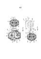
В варианте описанных выше примеров единственного объемного двигателя 1 или 100 на Фиг. 7а и 7b в разрезе показан двухступенчатый объемный двигатель, содержащий соответственно либо два двигателя 101 и 102 с прямозубыми зубчатыми колесами (Фиг. 7а), например, типа двигателя 100, либо роликовый или пластинчатый двигатель 200 (показан в разрезе) и двигатель 102 с прямозубыми зубчатыми колесами (фиг. 7b).In an embodiment of the above examples of a
Газы, высвобождаемые пиротехническим генератором, выталкиваются на вход 121 или 221 первой ступени (стрелки F7), образованной соответственно двигателем 101 с прямозубыми зубчатыми колесами (Фиг. 7а) или роликовым или пластинчатым двигателем 200 (Фиг. 1b), связанным на выходе со второй ступенью, установленной в виде тандема и образованной двигателем 102 с прямозубыми зубчатыми колесами. На выходах 122 или 222 первой ступени газы выбрасываются на вход 121 (стрелки F8) и внутрь (стрелки F9) второго двигателя 102 через рубашки 124. Предпочтительно второй двигатель 102 имеет размер, превышающий размер первого двигателя 101 или 200, чтобы избегать блокировки первого двигателя. Трансмиссионный 400 или центральный 600 вал первого двигателя, соответственно 101 или 200, установлен во вторичном валу 300 второго двигателя 102 (стрелки Ft), при этом трансмиссионный вал 500 второго двигателя обеспечивает приведение во вращение запускаемой установки. Газы выходят через выход 122 второго двигателя 102 (стрелки F10).The gases released by the pyrotechnic generator are pushed to the
В случае когда запускаемая установка является турбомашиной, содержащей вал каскада ВД, на Фиг. 8а-8с представлены примеры монтажа объемных двигателей 1 или 100 системы в соответствии с изобретением.In the case where the start-up installation is a turbomachine containing the shaft of the HP cascade, in FIG. 8a-8c show examples of mounting
Как показано в перспективе на Фиг. 8а, приемный вал, введенный в трансмиссионный вал 4b объемного двигателя 1, является валом 61 коробки 71 агрегатов, установленной на каскаде ВД 80 турбомашины 81. Коробка 71 агрегатов оснащена электрическим стартером 91, который представляет собой избыточный резервный элемент запуска.As shown in perspective in FIG. 8a, a receiving shaft inserted into the
Как показано в перспективе на Фиг. 8b, приемный вал 62 турбомашины 81 установлен на кожухе, жестко соединенном с зубчатым колесом коробки 71 агрегатов. Кожух является центробежным сцеплением 170 объемного двигателя 100.As shown in perspective in FIG. 8b, the receiving
Как показано в перспективе на Фиг. 8с, приемный вал, введенный в трансмиссионный вал 4b объемного двигателя 1, непосредственно является валом ВД 82 каскада ВД 80 турбомашины 81.As shown in perspective in FIG. 8c, a receiving shaft introduced into the
Изобретение не ограничивается описанными и показанными на фигурах примерами.The invention is not limited to the examples described and shown in the figures.
Например, в объемных двигателях можно использовать зубчатые колеса геликоидальной формы, обеспечивающие герметичность корпуса, или «прилегающие» зубчатые колеса.For example, in voluminous engines, helical gears can be used to ensure the tightness of the housing, or “adjacent” gears.
Альтернативно соединению посредством трения существуют другие средства сцепления: муфта свободного хода, электромагнитное зеркало (на токах Фуко), вязкое сцепление электрореологических или магнитореологических текучих сред.As an alternative to friction coupling, there are other means of coupling: a freewheel, an electromagnetic mirror (at Foucault currents), a viscous coupling of electrorheological or magnetorheological fluids.
Кроме двигателей с зубчатыми колесами и пластинчатых двигателей можно использовать роликовые роторы, используемые в сочетании с направляющими пазами в осевых фланцах.In addition to gear motors and rotary vane motors, roller rotors can be used that are used in combination with guide grooves in axial flanges.
Так, в случае установки типа термодинамического двигателя с циклом Стерлинга, или Эриксона, или эквивалентной установки, содержащей теплообменник или контур с регулируемым углом установки, приемный вал является валом привода теплообменника, и электронный блок включает в себя дополнительную функцию регулировки угла установки во время изохорных фаз цикла нагрева или конденсации цикла термодинамического двигателя.So, in the case of an installation of a type of a thermodynamic engine with a Sterling or Erickson cycle, or an equivalent installation containing a heat exchanger or a contour with an adjustable installation angle, the receiving shaft is the drive shaft of the heat exchanger, and the electronic unit includes an additional function to adjust the installation angle during isochoric phases heating or condensing cycle of a thermodynamic engine cycle.
Кроме того, естественно, число выступов или зубьев зубчатых колес может меняться, например, от 2 до 8 зубьев (как показано) и даже больше. Возвратные средства можно выбирать из: по меньшей мере, одной геликоидальной пружины, по меньшей мере, одной металлической пластинчатой пружины, электромагнита и поршневого газового патрона. Сигналы срабатывания включают в себя сигналы об обнаружении потенциального пожара термочувствительным компонентом и сигналы, управляемые вычислительным устройством.In addition, of course, the number of protrusions or teeth of the gears can vary, for example, from 2 to 8 teeth (as shown) and even more. Return means can be selected from: at least one helicoidal spring, at least one metal leaf spring, an electromagnet, and a piston gas cartridge. Triggering signals include potential fire detection by a thermosensitive component and signals controlled by a computing device.
Кроме того, электронная карта может включать в себя компонент измерения температуры, управляемый микроконтроллером, чтобы отслеживать высокие значения температур и позволять вычислительному устройству устанавливать срок службы без снижения безопасности работы.In addition, the electronic card may include a temperature measuring component controlled by a microcontroller to monitor high temperatures and allow the computing device to set a life without compromising operational safety.
Предпочтительно пиротехнические газогенераторы можно располагать в ряд в виде батареи в гнездах, установленных в барабане, обслуживаемом механизмом взвода, связанным с входным каналом корпуса объемного двигателя.Preferably, the pyrotechnic gas generators can be arranged in a row in the form of a battery in sockets mounted in a drum serviced by a cocking mechanism associated with an inlet channel of the surround engine housing.
Claims (13)
Applications Claiming Priority (3)
| Application Number | Priority Date | Filing Date | Title |
|---|---|---|---|
| FR1253938 | 2012-04-27 | ||
| FR1253938A FR2990004B1 (en) | 2012-04-27 | 2012-04-27 | METHOD AND SYSTEM FOR EMERGENCY STARTING ENERGY GENERATING ARCHITECTURE |
| PCT/FR2013/050863 WO2013160590A1 (en) | 2012-04-27 | 2013-04-18 | Method and system for the emergency start-up of an energy generator set |
Publications (2)
| Publication Number | Publication Date |
|---|---|
| RU2014142446A RU2014142446A (en) | 2016-06-20 |
| RU2621190C2 true RU2621190C2 (en) | 2017-06-01 |
Family
ID=46826641
Family Applications (1)
| Application Number | Title | Priority Date | Filing Date |
|---|---|---|---|
| RU2014142446A RU2621190C2 (en) | 2012-04-27 | 2013-04-18 | Method and system of emergency starting energy generation setting |
Country Status (12)
| Country | Link |
|---|---|
| US (1) | US10072580B2 (en) |
| EP (1) | EP2841742B1 (en) |
| JP (1) | JP6208216B2 (en) |
| KR (1) | KR102049130B1 (en) |
| CN (1) | CN104246181B (en) |
| CA (1) | CA2869361C (en) |
| ES (1) | ES2572093T3 (en) |
| FR (1) | FR2990004B1 (en) |
| IN (1) | IN2014DN08865A (en) |
| PL (1) | PL2841742T3 (en) |
| RU (1) | RU2621190C2 (en) |
| WO (1) | WO2013160590A1 (en) |
Families Citing this family (32)
| Publication number | Priority date | Publication date | Assignee | Title |
|---|---|---|---|---|
| FR3017417B1 (en) * | 2014-02-10 | 2018-10-26 | Safran Helicopter Engines | PYROTECHNIC DEVICE FOR DRIVING A ROTATING MACHINE |
| FR3019524B1 (en) * | 2014-04-03 | 2017-12-08 | Turbomeca | HELICOPTER ENGINE CHAIN INCORPORATING A PYROTECHNIC ENGINE ASSISTANCE MODULE AND HELICOPTER COMPRISING THE SAME |
| FR3019588B1 (en) | 2014-04-08 | 2019-06-14 | Safran Helicopter Engines | DEVICE FOR ASSISTING A SOLID PROPERGOL PROPULSIVE SYSTEM OF A MONOMOTING HELICOPTER, MONOMOTOR HELICOPTER COMPRISING SUCH DEVICE AND CORRESPONDING METHOD |
| US10054008B2 (en) * | 2015-02-09 | 2018-08-21 | United Technologies Corporation | Turbomachine accessory gearbox bracket |
| FR3033882B1 (en) * | 2015-03-16 | 2017-04-07 | Herakles | GAS GENERATOR |
| US10174678B2 (en) | 2016-02-12 | 2019-01-08 | United Technologies Corporation | Bowed rotor start using direct temperature measurement |
| US10436064B2 (en) | 2016-02-12 | 2019-10-08 | United Technologies Corporation | Bowed rotor start response damping system |
| US10508567B2 (en) | 2016-02-12 | 2019-12-17 | United Technologies Corporation | Auxiliary drive bowed rotor prevention system for a gas turbine engine through an engine accessory |
| US10443507B2 (en) | 2016-02-12 | 2019-10-15 | United Technologies Corporation | Gas turbine engine bowed rotor avoidance system |
| US10125636B2 (en) | 2016-02-12 | 2018-11-13 | United Technologies Corporation | Bowed rotor prevention system using waste heat |
| US10539079B2 (en) | 2016-02-12 | 2020-01-21 | United Technologies Corporation | Bowed rotor start mitigation in a gas turbine engine using aircraft-derived parameters |
| US10443505B2 (en) | 2016-02-12 | 2019-10-15 | United Technologies Corporation | Bowed rotor start mitigation in a gas turbine engine |
| US9664070B1 (en) | 2016-02-12 | 2017-05-30 | United Technologies Corporation | Bowed rotor prevention system |
| US10508601B2 (en) | 2016-02-12 | 2019-12-17 | United Technologies Corporation | Auxiliary drive bowed rotor prevention system for a gas turbine engine |
| US10040577B2 (en) | 2016-02-12 | 2018-08-07 | United Technologies Corporation | Modified start sequence of a gas turbine engine |
| US10125691B2 (en) | 2016-02-12 | 2018-11-13 | United Technologies Corporation | Bowed rotor start using a variable position starter valve |
| US10598047B2 (en) | 2016-02-29 | 2020-03-24 | United Technologies Corporation | Low-power bowed rotor prevention system |
| CN107404147A (en) * | 2016-05-20 | 2017-11-28 | 北京汽车股份有限公司 | Automobile and its emergency starting TRT |
| US10787933B2 (en) | 2016-06-20 | 2020-09-29 | Raytheon Technologies Corporation | Low-power bowed rotor prevention and monitoring system |
| US10358936B2 (en) | 2016-07-05 | 2019-07-23 | United Technologies Corporation | Bowed rotor sensor system |
| EP3273016B1 (en) | 2016-07-21 | 2020-04-01 | United Technologies Corporation | Multi-engine coordination during gas turbine engine motoring |
| US10618666B2 (en) | 2016-07-21 | 2020-04-14 | United Technologies Corporation | Pre-start motoring synchronization for multiple engines |
| EP3273006B1 (en) | 2016-07-21 | 2019-07-03 | United Technologies Corporation | Alternating starter use during multi-engine motoring |
| US10221774B2 (en) | 2016-07-21 | 2019-03-05 | United Technologies Corporation | Speed control during motoring of a gas turbine engine |
| US10384791B2 (en) | 2016-07-21 | 2019-08-20 | United Technologies Corporation | Cross engine coordination during gas turbine engine motoring |
| US10787968B2 (en) | 2016-09-30 | 2020-09-29 | Raytheon Technologies Corporation | Gas turbine engine motoring with starter air valve manual override |
| US10443543B2 (en) | 2016-11-04 | 2019-10-15 | United Technologies Corporation | High compressor build clearance reduction |
| US10823079B2 (en) | 2016-11-29 | 2020-11-03 | Raytheon Technologies Corporation | Metered orifice for motoring of a gas turbine engine |
| CN110291282B (en) * | 2016-12-15 | 2021-12-31 | 通用电气航空系统有限责任公司 | Air turbine starter with separator |
| US10823080B2 (en) | 2017-05-31 | 2020-11-03 | General Electric Company | Dual accessory gearbox |
| FR3082225B1 (en) | 2018-06-07 | 2020-06-05 | Safran Helicopter Engines | ASYMMETRIC PROPULSIVE HEAT RECOVERY SYSTEM |
| US11512645B2 (en) * | 2020-03-06 | 2022-11-29 | Goodrich Corporation | Solid-propellant gas generator assemblies and methods |
Citations (5)
| Publication number | Priority date | Publication date | Assignee | Title |
|---|---|---|---|---|
| FR1104252A (en) * | 1954-05-06 | 1955-11-17 | Snecma | Removable starter intended in particular for aircraft engines |
| FR1126010A (en) * | 1955-05-09 | 1956-11-13 | Air Equipement | Improvements to turbine starters |
| US2942415A (en) * | 1954-11-29 | 1960-06-28 | Bayard Gaston | System for feeding gases into a starting turbine |
| FR1334270A (en) * | 1962-09-25 | 1963-08-02 | Cessna Aircraft Co | Motor driven by pressurized fluid |
| RU2275957C1 (en) * | 2004-09-13 | 2006-05-10 | Российская Федерация, от имени которой выступает Государственный заказчик - Федеральное агентство по атомной энергии | Device for generating gas |
Family Cites Families (7)
| Publication number | Priority date | Publication date | Assignee | Title |
|---|---|---|---|---|
| FR1303228A (en) * | 1961-08-29 | 1962-09-07 | Sundstrand A G | Starter for motors |
| US3633360A (en) * | 1970-01-20 | 1972-01-11 | Talley Industries | Boost starter system |
| FR2475127A1 (en) * | 1980-02-06 | 1981-08-07 | Snecma | VOLUME VARIATION GAS GENERATOR |
| US6931856B2 (en) * | 2003-09-12 | 2005-08-23 | Mes International, Inc. | Multi-spool turbogenerator system and control method |
| FR2897895A1 (en) * | 2006-02-27 | 2007-08-31 | Hispano Suiza Sa | Transmission unit and starter-generator assembly for gas turbine, has synchronous generator and exciter placed on sides of pinion and with respective rotors mounted on shaft, and transmission unit and starter-generator placed in common case |
| FR2914697B1 (en) * | 2007-04-06 | 2012-11-30 | Turbomeca | DEVICE FOR ASSISTING THE TRANSIENT PHASES OF ACCELERATION AND DECELERATION |
| US8148834B2 (en) * | 2009-05-19 | 2012-04-03 | General Electric Company | Aircraft engine starting/generating system and method of control |
-
2012
- 2012-04-27 FR FR1253938A patent/FR2990004B1/en not_active Expired - Fee Related
-
2013
- 2013-04-18 CN CN201380021227.8A patent/CN104246181B/en not_active Expired - Fee Related
- 2013-04-18 RU RU2014142446A patent/RU2621190C2/en active
- 2013-04-18 PL PL13722505T patent/PL2841742T3/en unknown
- 2013-04-18 IN IN8865DEN2014 patent/IN2014DN08865A/en unknown
- 2013-04-18 WO PCT/FR2013/050863 patent/WO2013160590A1/en active Application Filing
- 2013-04-18 US US14/396,235 patent/US10072580B2/en active Active
- 2013-04-18 ES ES13722505T patent/ES2572093T3/en active Active
- 2013-04-18 EP EP13722505.8A patent/EP2841742B1/en active Active
- 2013-04-18 JP JP2015507577A patent/JP6208216B2/en not_active Expired - Fee Related
- 2013-04-18 CA CA2869361A patent/CA2869361C/en not_active Expired - Fee Related
- 2013-04-18 KR KR1020147028294A patent/KR102049130B1/en active IP Right Grant
Patent Citations (5)
| Publication number | Priority date | Publication date | Assignee | Title |
|---|---|---|---|---|
| FR1104252A (en) * | 1954-05-06 | 1955-11-17 | Snecma | Removable starter intended in particular for aircraft engines |
| US2942415A (en) * | 1954-11-29 | 1960-06-28 | Bayard Gaston | System for feeding gases into a starting turbine |
| FR1126010A (en) * | 1955-05-09 | 1956-11-13 | Air Equipement | Improvements to turbine starters |
| FR1334270A (en) * | 1962-09-25 | 1963-08-02 | Cessna Aircraft Co | Motor driven by pressurized fluid |
| RU2275957C1 (en) * | 2004-09-13 | 2006-05-10 | Российская Федерация, от имени которой выступает Государственный заказчик - Федеральное агентство по атомной энергии | Device for generating gas |
Non-Patent Citations (1)
| Title |
|---|
| АЛАБИН М.А. Запуск авиационных газотурбинных двигателей, М.: Машиностроение, 1968, с.22-23, с.37-39. * |
Also Published As
| Publication number | Publication date |
|---|---|
| PL2841742T3 (en) | 2016-08-31 |
| FR2990004A1 (en) | 2013-11-01 |
| US20150128592A1 (en) | 2015-05-14 |
| KR20150003189A (en) | 2015-01-08 |
| JP2015520821A (en) | 2015-07-23 |
| ES2572093T3 (en) | 2016-05-30 |
| FR2990004B1 (en) | 2014-04-18 |
| CA2869361A1 (en) | 2013-10-31 |
| EP2841742B1 (en) | 2016-03-30 |
| IN2014DN08865A (en) | 2015-05-22 |
| US10072580B2 (en) | 2018-09-11 |
| CN104246181B (en) | 2016-06-22 |
| JP6208216B2 (en) | 2017-10-04 |
| RU2014142446A (en) | 2016-06-20 |
| EP2841742A1 (en) | 2015-03-04 |
| KR102049130B1 (en) | 2019-11-26 |
| WO2013160590A1 (en) | 2013-10-31 |
| CA2869361C (en) | 2020-06-30 |
| CN104246181A (en) | 2014-12-24 |
Similar Documents
| Publication | Publication Date | Title |
|---|---|---|
| RU2621190C2 (en) | Method and system of emergency starting energy generation setting | |
| JP2015520821A5 (en) | ||
| US2842937A (en) | Aircraft engine cartridge starter control system | |
| EP3660324A1 (en) | Pump and sealing system | |
| CN109690052B (en) | Shaft breaking device for generator | |
| US3451214A (en) | Cold engine start facilitating apparatus | |
| RU2660725C2 (en) | Aircraft gas turbine engine emergency starting system and method | |
| CN110291282B (en) | Air turbine starter with separator | |
| KR100749003B1 (en) | Device of thrust termination for rocket motor | |
| EP3019703B1 (en) | Engine propulsion system | |
| CN106458323A (en) | Drive chain for a helicopter incorporating a pyrotechnic assistance drive module and helicopter comprising same | |
| US8763404B2 (en) | Systems, apparatuses, and methods of harnessing thermal energy of gas turbine engines | |
| RU2541595C1 (en) | Safety device for aircraft onboard automatics detonation circuits | |
| WO2019115271A1 (en) | Aircraft engine generator disconnect device | |
| RU2400688C1 (en) | System of rocket launching from launch container | |
| EP2842873B1 (en) | Short term, autonomous, electrical power supply system | |
| RU2794302C1 (en) | Gas compressor unit | |
| JP2009030529A (en) | Safety device | |
| RU2460965C1 (en) | Missile | |
| RU2329418C1 (en) | Chassis of military caterpillar vehicle | |
| EP2150707A1 (en) | Locking device | |
| US20190338709A1 (en) | Auxiliary system for driving a shaft of a helicopter propulsion system | |
| BR112016005119B1 (en) | AIRCRAFT TURBO-MACHINE EMERGENCY START SYSTEM, AIRCRAFT AND EMERGENCY START-UP METHOD OF AN AIRCRAFT TURBO MACHINE | |
| ITTO960020A1 (en) | RACK MOTOR |
Legal Events
| Date | Code | Title | Description |
|---|---|---|---|
| PD4A | Correction of name of patent owner |