RU2620915C2 - Apodized hybrid diffractive-refractive iol for pseudoaccommodation - Google Patents
Apodized hybrid diffractive-refractive iol for pseudoaccommodation Download PDFInfo
- Publication number
- RU2620915C2 RU2620915C2 RU2014135326A RU2014135326A RU2620915C2 RU 2620915 C2 RU2620915 C2 RU 2620915C2 RU 2014135326 A RU2014135326 A RU 2014135326A RU 2014135326 A RU2014135326 A RU 2014135326A RU 2620915 C2 RU2620915 C2 RU 2620915C2
- Authority
- RU
- Russia
- Prior art keywords
- diffraction
- refractive
- region
- optical power
- regions
- Prior art date
Links
Images
Classifications
-
- A—HUMAN NECESSITIES
- A61—MEDICAL OR VETERINARY SCIENCE; HYGIENE
- A61F—FILTERS IMPLANTABLE INTO BLOOD VESSELS; PROSTHESES; DEVICES PROVIDING PATENCY TO, OR PREVENTING COLLAPSING OF, TUBULAR STRUCTURES OF THE BODY, e.g. STENTS; ORTHOPAEDIC, NURSING OR CONTRACEPTIVE DEVICES; FOMENTATION; TREATMENT OR PROTECTION OF EYES OR EARS; BANDAGES, DRESSINGS OR ABSORBENT PADS; FIRST-AID KITS
- A61F2/00—Filters implantable into blood vessels; Prostheses, i.e. artificial substitutes or replacements for parts of the body; Appliances for connecting them with the body; Devices providing patency to, or preventing collapsing of, tubular structures of the body, e.g. stents
- A61F2/02—Prostheses implantable into the body
- A61F2/14—Eye parts, e.g. lenses, corneal implants; Implanting instruments specially adapted therefor; Artificial eyes
- A61F2/16—Intraocular lenses
- A61F2/1613—Intraocular lenses having special lens configurations, e.g. multipart lenses; having particular optical properties, e.g. pseudo-accommodative lenses, lenses having aberration corrections, diffractive lenses, lenses for variably absorbing electromagnetic radiation, lenses having variable focus
- A61F2/1654—Diffractive lenses
-
- A—HUMAN NECESSITIES
- A61—MEDICAL OR VETERINARY SCIENCE; HYGIENE
- A61F—FILTERS IMPLANTABLE INTO BLOOD VESSELS; PROSTHESES; DEVICES PROVIDING PATENCY TO, OR PREVENTING COLLAPSING OF, TUBULAR STRUCTURES OF THE BODY, e.g. STENTS; ORTHOPAEDIC, NURSING OR CONTRACEPTIVE DEVICES; FOMENTATION; TREATMENT OR PROTECTION OF EYES OR EARS; BANDAGES, DRESSINGS OR ABSORBENT PADS; FIRST-AID KITS
- A61F2/00—Filters implantable into blood vessels; Prostheses, i.e. artificial substitutes or replacements for parts of the body; Appliances for connecting them with the body; Devices providing patency to, or preventing collapsing of, tubular structures of the body, e.g. stents
- A61F2/02—Prostheses implantable into the body
- A61F2/14—Eye parts, e.g. lenses, corneal implants; Implanting instruments specially adapted therefor; Artificial eyes
- A61F2/16—Intraocular lenses
- A61F2/1613—Intraocular lenses having special lens configurations, e.g. multipart lenses; having particular optical properties, e.g. pseudo-accommodative lenses, lenses having aberration corrections, diffractive lenses, lenses for variably absorbing electromagnetic radiation, lenses having variable focus
- A61F2/1616—Pseudo-accommodative, e.g. multifocal or enabling monovision
- A61F2/1618—Multifocal lenses
-
- G—PHYSICS
- G02—OPTICS
- G02C—SPECTACLES; SUNGLASSES OR GOGGLES INSOFAR AS THEY HAVE THE SAME FEATURES AS SPECTACLES; CONTACT LENSES
- G02C2202/00—Generic optical aspects applicable to one or more of the subgroups of G02C7/00
- G02C2202/20—Diffractive and Fresnel lenses or lens portions
-
- G—PHYSICS
- G02—OPTICS
- G02C—SPECTACLES; SUNGLASSES OR GOGGLES INSOFAR AS THEY HAVE THE SAME FEATURES AS SPECTACLES; CONTACT LENSES
- G02C7/00—Optical parts
- G02C7/02—Lenses; Lens systems ; Methods of designing lenses
- G02C7/04—Contact lenses for the eyes
- G02C7/041—Contact lenses for the eyes bifocal; multifocal
- G02C7/044—Annular configuration, e.g. pupil tuned
-
- G—PHYSICS
- G02—OPTICS
- G02C—SPECTACLES; SUNGLASSES OR GOGGLES INSOFAR AS THEY HAVE THE SAME FEATURES AS SPECTACLES; CONTACT LENSES
- G02C7/00—Optical parts
- G02C7/02—Lenses; Lens systems ; Methods of designing lenses
- G02C7/06—Lenses; Lens systems ; Methods of designing lenses bifocal; multifocal ; progressive
Landscapes
- Health & Medical Sciences (AREA)
- Ophthalmology & Optometry (AREA)
- Cardiology (AREA)
- Oral & Maxillofacial Surgery (AREA)
- Transplantation (AREA)
- Engineering & Computer Science (AREA)
- Biomedical Technology (AREA)
- Heart & Thoracic Surgery (AREA)
- Vascular Medicine (AREA)
- Life Sciences & Earth Sciences (AREA)
- Animal Behavior & Ethology (AREA)
- General Health & Medical Sciences (AREA)
- Public Health (AREA)
- Veterinary Medicine (AREA)
- Prostheses (AREA)
- Eyeglasses (AREA)
- Diffracting Gratings Or Hologram Optical Elements (AREA)
Abstract
Description
ОБЛАСТЬ ТЕХНИКИFIELD OF TECHNOLOGY
Настоящее описание относится, в основном, к офтальмологическим линзам и, более конкретно, к аподизированным гибридным дифракционно-рефракционным интраокулярным линзам (ИОЛ) для псевдоаккомодации.The present description relates mainly to ophthalmic lenses and, more specifically, to apodized hybrid diffraction-refractive intraocular lenses (IOLs) for pseudo-accommodation.
УРОВЕНЬ ТЕХНИКИBACKGROUND
ИОЛ может быть имплантирована в глаз во время операции по удалению катаракты для замены природного хрусталика глаза. Цилиарные мышцы изменяют оптическую силу природного хрусталика глаза, обеспечивая аккомодацию для видения объектов, находящихся на различных расстояниях от глаза. Однако многие ИОЛ обеспечивают монофокальное действие, не предусматривая возможность аккомодации. Некоторые мультифокальные ИОЛ обладают дистанционной оптической силой, а также ближней оптической силой (например, за счет использования дифракционных структур), обеспечивая определенную степень псевдоаккомодации.An IOL can be implanted in the eye during cataract surgery to replace the natural lens of the eye. The ciliary muscles alter the optical power of the natural lens of the eye, providing accommodation for seeing objects at different distances from the eye. However, many IOLs provide a monofocal effect, without providing for the possibility of accommodation. Some multifocal IOLs have remote optical power as well as near optical power (for example, due to the use of diffraction structures), providing a certain degree of pseudo accommodation.
КРАТКОЕ ОПИСАНИЕSHORT DESCRIPTION
В некоторых вариантах реализации офтальмологическая линза содержит оптический элемент. Указанный оптический элемент имеет оптическую ось и поверхности, включая переднюю поверхность и заднюю поверхность. По меньшей мере одна из поверхностей имеет внутреннюю рефракционную область и рефракционно-дифракционную структуру, расположенную снаружи указанной внутренней рефракционной области в направлении от указанной оптической оси. Внутреннюю рефракционную область выполняют с возможностью рефракционного содействия оптической силе дистанционного фокуса. Указанная рефракционно-дифракционная структура содержит одну или более дифракционных областей и одну или боле рефракционных областей. Дифракционную область выполняют с возможностью дифракционного содействия многозонной оптической силе, а рефракционную область выполняют с возможностью рефракционного содействия оптической силе дистанционного фокуса.In some embodiments, the ophthalmic lens comprises an optical element. The specified optical element has an optical axis and surfaces, including the front surface and the rear surface. At least one of the surfaces has an internal refractive region and a refractive-diffractive structure located outside said internal refractive region in a direction away from said optical axis. The internal refractive region is performed with the possibility of refractive assistance to the optical power of the remote focus. The specified refractive-diffraction structure contains one or more diffraction regions and one or more refractive regions. The diffraction region is performed with the possibility of diffraction assistance to the multi-band optical power, and the refractive region is performed with the possibility of refraction assistance to the optical power of the remote focus.
КРАТКОЕ ОПИСАНИЕ ЧЕРТЕЖЕЙBRIEF DESCRIPTION OF THE DRAWINGS
Далее в качестве примеров будут более подробно описаны иллюстративные варианты реализации настоящего описания со ссылкой на приложенные фигуры, в которых:Next, as examples, illustrative embodiments of the present description will be described in more detail with reference to the attached figures, in which:
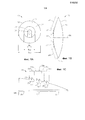
Фиг. 1A-1C схематически иллюстрируют гибридную дифракционно-рефракционную интраокулярную линзу (ИОЛ) в соответствии с некоторыми вариантами реализации: Фиг. 1А иллюстрирует вид на переднюю поверхность ИОЛ, Фиг. 1В иллюстрирует поперечное сечение ИОЛ и Фиг. 1С иллюстрирует более подробный вид поперечного сечения ИОЛ;FIG. 1A-1C schematically illustrate a hybrid diffraction-refractive intraocular lens (IOL) in accordance with some embodiments: FIG. 1A illustrates a view of the front surface of the IOL; FIG. 1B illustrates the cross section of the IOL and FIG. 1C illustrates a more detailed cross-sectional view of the IOL;
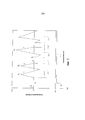
Фиг. 2 иллюстрирует пример профиля внутренней рефракционной области и рефракционно-дифракционную структуру;FIG. 2 illustrates an example of a profile of an internal refractive region and a refractive-diffraction structure;
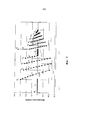
Фиг. 3 иллюстрирует другой пример профиля внутренней рефракционной области и рефракционно-дифракционную структуру; иFIG. 3 illustrates another example of a profile of an internal refractive region and a refractive-diffraction structure; and
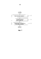
Фиг. 4 иллюстрирует пример способа получения оптического элемента гибридной дифракционно-рефракционной ИОЛ.FIG. 4 illustrates an example of a method for producing an optical element of a hybrid diffractive-refractive IOL.
ОПИСАНИЕ ИЛЛЮСТРАТИВНЫХ ВАРИАНТОВ РЕАЛИЗАЦИИDESCRIPTION OF ILLUSTRATIVE EMBODIMENTS
Ссылаясь на данное описание и чертежи, подробно представлены иллюстративные варианты описанных приборов, систем и способов. Описание и чертежи не подразумеваются исчерпывающими или иным образом определяющими пределы или ограничивающими формулу изобретения до конкретных вариантов реализации, показанных на чертежах и раскрытых в данном описании. Несмотря на то, что чертежи представляют собой возможные варианты реализации, указанные чертежи не обязательно следует масштабировать, а некоторые детали могут быть увеличены, удалены или частично разрезаны для лучшей иллюстрации вариантов реализации.Referring to this description and drawings, illustrative options of the described devices, systems and methods are presented in detail. The description and drawings are not intended to exhaustively or otherwise define the limits or limit the claims to the specific embodiments shown in the drawings and disclosed herein. Although the drawings are possible implementations, these drawings need not be scaled, and some details may be enlarged, deleted, or partially cut to better illustrate the embodiments.
Фиг. 1A-1C схематически иллюстрируют гибридную дифракционно-рефракционную интраокулярную линзу (ИОЛ) 10 в соответствии с некоторыми вариантами реализации. Фиг. 1A иллюстрирует вид на переднюю поверхность 14 ИОЛ 10, Фиг. 1В иллюстрирует поперечное сечение ИОЛ 10, и Фиг. 1С иллюстрирует более подробный вид поперечного сечения ИОЛ 10.FIG. 1A-1C schematically illustrate a hybrid diffraction-refractive intraocular lens (IOL) 10 in accordance with some embodiments. FIG. 1A illustrates a view of the
Гибридная дифракционно-рефракционная ИОЛ 10 содержит смесь дифракционных и рефракционных областей, которые обеспечивают многозонное зрение. «Многозонное» относится к двум или трем любым из следующих дистанций зрения: ближнее, среднее и дальнее (или дистанционное) зрение. Ближнее зрение относится к видению ближних объектов, находящихся на расстоянии около 2 или менее футов от глаза. Среднее зрение относится к видению объектов на среднем расстоянии, находящихся на удалении от около 2 до 20 футов (например, от 2 до 3 футов) от глаза. Дистанционное зрение относится к видению удаленных объектов, находящихся на расстоянии около 20 или более футов от глаза «Ближнее зрение» может включать ближнее зрение и среднее зрение.Hybrid diffraction-refractive IOL 10 contains a mixture of diffraction and refraction regions that provide multi-zone vision. “Multi-zone” refers to two or three of any of the following distances: near, middle, and far (or distant) vision. Near vision refers to seeing near objects that are about 2 feet or less from the eye. Medium vision refers to seeing objects at an average distance that are about 2 to 20 feet (for example, 2 to 3 feet) from the eye. Remote vision refers to the vision of distant objects about 20 or more feet from the eye. Near vision may include near vision and secondary vision.
Область ИОЛ 10 может способствовать оптической силе зоны для обеспечения видения в этой зоне за счет фокусировки световых лучей от объекта в этой зоне на фокусной точке сетчатки. Например, область может способствовать ближней оптической силе с обеспечением ближнего зрения за счет фокусировки световых лучей от объекта, находящегося вблизи, на ближней фокусной точке, может способствовать оптической силе среднего фокуса с обеспечением среднего зрения за счет фокусировки световых лучей от объекта, находящегося на среднем расстоянии, на средней фокусной точке, и/или может способствовать дистанционной оптической силе с обеспечением дистанционного зрения за счет фокусировки световых лучей от удаленного объекта на дистанционной фокусной точке.Region IOL 10 can contribute to the optical power of the zone to provide vision in this zone due to the focusing of light rays from an object in this zone at the focal point of the retina. For example, a region can contribute to near optical power by providing near vision by focusing light rays from an object located close to a near focal point, and can contribute to optical power by medium focus by providing medium vision by focusing light rays from an object located at an average distance , at the mid-focal point, and / or can contribute to remote optical power while providing remote vision by focusing light rays from a distant object to instantaneous focal point.
ИОЛ 10 содержит оптический элемент. Оптический элемент 12 может иметь любой подходящий диаметр Dопт, например, в диапазоне от 5 до 7 мм, такое значение как от 5,5 до 6,5 мм, например, около 6 мм. Оптический элемент 12 может содержать любой подходящий биосовместимый материал, такой как биосовместимый полимерный материал. Примеры включают, без ограничения, мягкий акриловый материал (такой как ACRYSOF, поперечно-сшитый сополимер 2-фенилэтилакрилата и 2-фенилэтилметакрилата), силикон и гидрогель. Этот материал может содержать оптические фильтры, которые могут улучать остроту зрения и/или защищать ткань сетчатки от потенциально вредных длин волн. Хотя это не показано, ИОЛ 10 также может содержать одну или более фиксирующих элементов (например, гаптических элементов), которые могут облегчать размещение ИОЛ 10 в глазу пациента.IOL 10 contains an optical element. The
Оптический элемент 12 имеет переднюю поверхность 14 и заднюю поверхность 16, последовательно центрированные относительно оптической оси OA. Передняя поверхность 14 и задняя поверхность 16 могут иметь любой подходящий основной профиль. В иллюстрированном примере каждая поверхность 14, 16 имеет выпуклый основной профиль. В других вариантах реализации одна или обе поверхности могут иметь вогнутый или плоский основной профиль. Номинальная оптическая сила оптического элемента 12 может быть определена по основным профилям в комбинации с коэффициентом преломления материала, образующего оптический элемент 12. В некоторых вариантах реализации номинальная оптическая сила может быть монофокальной рефракционной силой оптического элемента 12 для зрачков с диаметром менее чем диаметр Dвн внутренней рефракционной области 20 (описанной ниже).The
В некоторых вариантах реализации передняя поверхность 14 имеет вспомогательный профиль, помимо основного профиля. В данном примере вспомогательный профиль передней поверхности 14 содержит внутреннюю рефракционную область 20, рефракционно-дифракционную структуру 22 и внешнюю рефракционную область 24. Внутренняя рефракционная область 20 расположена вокруг оптической оси OA, а диаметр Dвн внутренней рефракционной области 20 может иметь любое подходящее значение, такое как значение в любом из следующих диапазонов: от 0,8 до 1 мм, от 0,90 до 1,0 мм, например приблизительно 0,938 мм.In some embodiments, the
Внутренняя рефракционная область 20 может быть выполнена с возможностью рефракционного содействия оптической силе дистанционного фокуса. Внутренняя рефракционная область 20 может рефракционно способствовать оптической силе дистанционного фокуса за счет преломления световых лучей от удаленного объекта до фокуса лучей на дистанционной фокусной точке сетчатки с обеспечением дистанционного видения.The internal
В некоторых вариантах реализации внутренняя рефракционная область 20 может обеспечивать некоторые преимущества. Например, рефракционная область в целом обеспечивает более высокую передачу энергии, чем дифракционная область. Поэтому ИОЛ с внутренней рефракционной областью 20 обеспечивает возможность более высокой передачи энергии, чем ИОЛ с центральной дифракционной областью. В качестве другого примера, рефракционная область обладает более высокими допусками к местоположению, в котором световые лучи входят в указанную область, а также к небольшим рефракционным аномалиям, чем дифракционная область. Следовательно, ИОЛ с центральной рефракционной областью 20 обладает более высокими допусками к смещению центра ИОЛ в глазу, чем ИОЛ с центральной дифракционной областью.In some embodiments, the internal
Рефракционно-дифракционная структура 22 расположена снаружи указанной внутренней рефракционной области 20 в направлении от оптической оси OA. Диаметр Dр-д рефракционно-дифракционной структуры 22 может иметь любое подходящее значение, такое как от 3 до 4 мм, от 3,2 до 3,8 мм или от 3,3 до 3,5 мм, например приблизительно 3,4 мм. В некоторых вариантах реализации диаметр Dр-д не может быть больше чем диаметр среднего зрачка. Для более крупных зрачков на внешнюю рефракционную зону 24 может быть направлено большее количество энергии для дистанционного фокуса, чтобы минимизировать эффект гало.The refractive-
В некоторых вариантах реализации рефракционно-дифракционная структура 22 содержит одну или более дифракционных областей 30 (30а-с) и одну или более рефракционных областей 32 (32а-b). Дифракционная область 30 может быть выполнена с возможностью дифракционного содействия за счет дифракции световых лучей с помощью дифракционной решетки, с обеспечением многозонного видения. Дифракционная область 30 может способствовать многозонной оптической силе, как описано выше. Рефракционная область 32 может быть выполнена с возможностью рефракционного содействия оптической силе дистанционного фокуса таким же образом, как и внутренняя рефракционная область 20.In some embodiments, the
В некоторых вариантах реализации дифракционная область 30 имеет множество концентрических колец, которые образуют дифракционную решетку. Указанная дифракционная решетка преломляет световые лучи для фокусировки света одновременно в двух местах с получением двух отдельных фокусных точек, таких как любые две из следующих: дистанционные, средние или ближние фокусные точки. Дифракционные области 30 имеют ступеньки (или эшелетт) 36 из отдельных ступенек высотой 40, которые преломляют свет на один или более порядков. Расположение ступенек 36 определяет зону ближнего зрения, а высота ступенек 40 каждой из ступени 36 контролирует долю света, которая направлена на фокусные точки. В общем, более высокие ступени 36 направляют большее количество света в ближнюю фокусную точку, а более низкие ступени 36 направляют большее количество света в дистанционную фокусную точку.In some embodiments, the
Ступени 36 могут иметь любую подходящую высоту ступеней 40. В некоторых вариантах реализации ступени 36 аподизированы, так что высота ступеней 40, в основном, уменьшается с увеличением расстояния от оптической оси OA. Например, высота ступеней 40 может составлять 1,3 микрона возле центра и уменьшаться до 0,2 микрона возле периметра. Ступени 36 могут быть аподизированы любым подходящим способом. В некоторых вариантах реализации ступени 36 поперек различных дифракционных областей 30 могут быть точно аподизированы, так что высота ступеней 40 уменьшается (или по меньшей мере не увеличивается) с увеличением расстояния от оптической оси OA. В других вариантах реализации ступени 36 поперек различных дифракционных областей 30 могут быть, в основном, аподизированы так, что большинство высот ступеней 40 уменьшается (или по меньшей мере не увеличивается) с увеличением расстояния от оптической оси OA, но по меньшей мере одна высота ступени «не аподизированной» ступени, которая находится гораздо дальше от оптической оси OA, является больше, чем высота ступени, которая расположена ближе к оптической оси OA. В других вариантах реализации ступени 36 в дифракционной области 30 могут быть аподизированы, а ступени 36 поперек других дифракционных областей 30 не обязательно (но могут быть) аподизированы. Например, высота ступеней 40 дифракционной области 30а может снижаться с увеличением расстояния от оптической оси ОА, а высота ступеней 40 в дифракционной области 30b может точно так же уменьшаться, но высота не аподизированной ступени 36 дифракционной области 30b может быть больше, чем высота ступени 36 дифракционной области 30а.
В некоторых вариантах реализации аподизация обеспечивает возможность постепенного перехода света между дистанционными, средними и ближними фокусными точками. В этих вариантах реализации более высокие ступени 36 направляют большее количество света в ближнюю фокусную точку, а более низкие ступени 36 направляют большее количество света в дистанционную фокусную точку. Постепенный переход энергии между рефракциями приводит к все более и более мелким точкам дефокусировки. Вкратце, свет проходит через дифракционную область 30, ступени 36 дают волны, которые пересекают различные фокусные точки с образованием отдельных изображений.In some implementations, apodization allows for the gradual transition of light between distant, middle, and near focal points. In these embodiments,
Световая энергия может быть распределена любым подходящим образом. Например, X% может быть направлено в дистанционную фокусную точку, и Y% может быть направлено в ближнюю фокусную точку, где X равен 50 или более, такое значение как от 55 до 65, например, приблизительно 60, такое значение как 58,9, и Y равен 50 или менее, такое значение как от 20 до 30, например, приблизительно 26, такое значение как 25,5.Light energy can be distributed in any suitable way. For example, X% can be sent to the focal point, and Y% can be sent to the near focal point, where X is 50 or more, a value from 55 to 65, for example, about 60, a value like 58.9, and Y is 50 or less, a value such as from 20 to 30, for example, approximately 26, a value such as 25.5.
Высота ступеней 40 может быть рассчитана любым подходящим образом. Например, высота ступеней H может быть рассчитана по Уравнению (1):The height of the
H = ![]()
![]()
где P представляет собой фазовую высоту, λ представляет собой заданную длину волны, nИОЛ представляет собой коэффициент преломления ИОЛ, и nср представляет собой коэффициент преломления среды, в которую помещена ИОЛ. Заданная длина волны может быть узкой областью видимого спектра, которую используют для определения оптических характеристик ИОЛ для минимизации хроматической аберрации. P может быть обобщен как Pm, где m = 0, 1, 2, 3, …. Параметр m может быть выбран в соответствии с аддидацией и/или внешней границей аподизированной зоны. Если длина волны λ, коэффициент преломления ИОЛ nИОЛ и коэффициент преломления среды nср являются постоянными, то Pm может быт использован для обозначения высоты ступени.where P is the phase height, λ is the predetermined wavelength, n IOL is the refractive index of the IOL, and n cp is the refractive index of the medium in which the IOL is placed. The specified wavelength may be a narrow region of the visible spectrum, which is used to determine the optical characteristics of the IOL to minimize chromatic aberration. P can be generalized as P m , where m = 0, 1, 2, 3, .... The parameter m can be selected in accordance with the add and / or external boundary of the apodized zone. If the wavelength λ, the refractive index of the IOL n IOL and the refractive index of the medium n sr are constant, then P m can be used to indicate the height of the step.
Внешняя рефракционная область 19 передней поверхности распространяется от внешней границы рефракционно-дифракционной структуры 22 до периферии оптического элемента 12. Внешняя рефракционная область 19 может оказывать рефракционное содействие оптической силе дистанционного фокуса для зрачков крупных размеров, например, в условиях низкого освещения.The external refractive region 19 of the front surface extends from the external border of the refractive-
В некоторых вариантах реализации оптический элемент 12 может обеспечивать более высокое значение модуляционной передаточной функции (МПФ) по сравнению с известными ИОЛ. Оптический элемент 12 может достигать значения функционального чтения 20/40 или лучше на ближнем расстоянии для зрачка среднего размера.In some embodiments, the
Фиг. 2 иллюстрирует пример профиля внутренней рефракционной области 20 и рефракционно-дифракционную структуру 22. В этом примере рефракционно-дифракционная структура 22 содержит дифракционные области 30 (30a-c) и рефракционные области 32 (32a-b). Дифракционные области 30 имеют ступени 1-4 с высотой ступеней P1-P4. Ступень 4 представляет собой не аподизированную ступень. Ступень 4 находится гораздо дальше от оптической оси ОА, чем ступень 1, но высота ступени P4 больше, чем высота ступени P1. В некоторых вариантах реализации высота ступеней P0 и P3 может быть одинаковой.FIG. 2 illustrates an example of a profile of an internal
Фиг. 3 иллюстрирует другой пример профиля внутренней рефракционной области 20 и рефракционно-дифракционную структуру 22. В этом примере рефракционно-дифракционная структура 22 содержит дифракционные области 30 (30a-b) и рефракционную область 32 (32a). Дифракционные области 30 имеют ступени 1-11 с высотой ступеней P1-P11. Ступень 6 представляет собой не аподизированную ступень. Ступень 6 находится гораздо дальше от оптической оси ОА, чем ступени 1-4, но высота ступени P6 больше, чем высота ступеней P1-P4.FIG. 3 illustrates another example of the profile of the internal
Фиг. 4 иллюстрирует пример способа получения оптического элемента 12 гибридной дифракционно-рефракционной ИОЛ 10. Оптический элемент 12 может быть изготовлен в соответствии с любым подходящим способом. В некоторых вариантах реализации профили поверхностей проектируют на стадии 110, а затем изготавливают оптический элемент 12 с указанными профилями, используя любой подходящий способ. В некоторых вариантах реализации заготовку линзы помещают в держатель для линз на стадии 112. Затем заготовке линзы придают форму на стадии 114 с получением указанных профилей. Подходящие методики придания формы могут включать любой способ формовки, пригодный для указанных материалов, включая, но не ограничиваясь этим, формование, абляцию и/или обточку.FIG. 4 illustrates an example of a method for producing an
В одном примере указанный способ включает установку заготовки линзы в держатель для линз. Заготовке линзы придают форму с получением оптического элемента, имеющего оптическую ось и множество поверхностей, содержащих переднюю поверхность и заднюю поверхность. Формование включает придание формы по меньшей мере одной из поверхностей с получением внутренней рефракционной области и рефракционно-дифракционной структуры, расположенной снаружи указанной внутренней рефракционной области в направлении от указанной оптической оси. Внутреннюю рефракционную область выполняют с возможностью рефракционного содействия оптической силе дистанционного фокуса. Указанная рефракционно-дифракционная структура содержит одну или более дифракционных областей и одну или боле рефракционных областей. Дифракционную область выполняют с возможностью дифракционного содействия многозонной оптической силе, а рефракционную область выполняют с возможностью рефракционного содействия оптической силе дистанционного фокуса.In one example, said method includes inserting a lens preform into a lens holder. The lens blank is shaped into an optical member having an optical axis and a plurality of surfaces comprising a front surface and a rear surface. Molding involves shaping at least one of the surfaces to provide an internal refractive region and a refractive-diffractive structure located outside the specified internal refractive region in the direction from the specified optical axis. The internal refractive region is performed with the possibility of refractive assistance to the optical power of the remote focus. The specified refractive-diffraction structure contains one or more diffraction regions and one or more refractive regions. The diffraction region is performed with the possibility of diffraction assistance to the multi-band optical power, and the refractive region is performed with the possibility of refraction assistance to the optical power of the remote focus.
Профиль ИОЛ 10 может быть рассчитан с помощью компонента, который может включать интерфейс, логический, запоминающий и/или другой подходящий элемент, любой из которых может включать аппаратное оборудование и/или программное оборудование. Интерфейс может принимать входящие данные, отправлять исходящие данные, обрабатывать входящие и/или исходящие данные и/или выполнять другие подходящие операции. Логический элемент может выполнять операции указанного компонента, например выполнять инструкции для создания исходящих данных из входящих данных. Логический элемент может быть закодирован в памяти и может выполнять операции при их исполнении компьютером. Логический элемент может быть процессором, таким как один или более компьютеров, одним или более микропроцессорами, одним или более приложениями и/или другим логическим элементом. Память может хранить информацию и может включать один или более реальных, машиночитаемых и/или машиноисполняемых информационных носителей. Примеры памяти включают компьютерную память (например, Оперативное Запоминающее Устройство (ОЗУ) или Постоянное Запоминающее Устройство (ПЗУ)), массовое запоминающее устройство (например, жесткий диск), съемный информационный носитель (например, компакт-диск (CD) или цифровой видеодиск (DVD)), базы данных и/или сетевые системы хранения данных (например, сервер) и/или другие машиночитаемые носители.The
В конкретных вариантах реализации расчет профиля ИОЛ 10 может быть выполнен одним или более машиночитаемыми носителями, которые закодированы компьютерной программой, программным обеспечением, машиноисполняемыми инструкциями и/или инструкциями, которые могут быть выполнены компьютером. В конкретных вариантах реализации указанные операции могут быть выполнены одним или более машиночитаемыми информационными носителями, содержащими компьютерную программу, и/или закодированными компьютерной программой, и/или имеющими записанную и/или закодированную компьютерную программу.In specific embodiments, the calculation of the profile of the
Хотя настоящее раскрытие было описано в контексте определенных вариантов реализации, специалистам в данной области понятны модификации (такие как изменения, замещения, дополнения, опущения и/или другие модификации) указанных вариантов реализации. Соответственно, к этим вариантам реализации могут быть сделаны модификации без отклонения от рамок настоящего изобретения. Например, могут быть сделаны модификации к системам и аппаратам, описанным в настоящем документе. Компоненты систем и аппаратов могут быть интегрированными или отдельными, а операции систем и аппаратов могут быть выполнены с помощью большего, меньшего количества или с помощью других компонентов. В качестве другого примера, могут быть сделаны модификации к способам, описанным в настоящем документе. Способы могут включать большее, меньшее количество стадий или другие стадии, и эти стадии могут быть выполнены в любом подходящем порядке.Although the present disclosure has been described in the context of certain embodiments, those skilled in the art will understand modifications (such as changes, substitutions, additions, omissions, and / or other modifications) to these embodiments. Accordingly, modifications can be made to these embodiments without departing from the scope of the present invention. For example, modifications can be made to the systems and apparatuses described herein. Components of systems and apparatuses may be integrated or separate, and operations of systems and apparatuses may be performed using more, less, or other components. As another example, modifications to the methods described herein may be made. The methods may include more, fewer stages or other stages, and these stages can be performed in any suitable order.
Возможны другие модификации, без отклонения от общей идеи настоящего изобретения. Например, представленное описание иллюстрирует варианты реализации в конкретных практических применениях, специалистам в данной области понятны другие применения. Кроме того, в данной области техники, рассмотренной в настоящем документе, происходит дальнейшее изменение, и описанные системы, аппараты и способы следует использовать с такими будущими изменениями.Other modifications are possible without deviating from the general idea of the present invention. For example, the description provided illustrates implementation options for specific practical applications; other applications are understood by those skilled in the art. In addition, a further change is occurring in the art discussed herein, and the described systems, apparatuses and methods should be used with such future changes.
Рамки настоящего изобретения не следует определять со ссылкой на представленное описание. В соответствии с патентным законодательством, настоящее описание поясняет и иллюстрирует принципы и способы использования настоящего изобретения с помощью иллюстративных вариантов реализации. Настоящее описание дает возможность специалистам в данной области использовать представленные системы, аппараты и способы в различных вариантах реализации и с различными модификациями, но его не следует использовать для определения рамок настоящего изобретения.The scope of the present invention should not be determined with reference to the description provided. In accordance with patent law, the present description explains and illustrates the principles and methods of using the present invention using illustrative embodiments. The present description allows specialists in this field to use the presented systems, devices and methods in various embodiments and with various modifications, but it should not be used to determine the scope of the present invention.
Рамки настоящего изобретения следует определять со ссылкой на формулу изобретения и полный объем эквивалентов, на которые дает права указанная формула изобретения. Все термины в формуле изобретения следует толковать в самом широком рациональном понимании и их стандартном значении, понятном для специалистов в данной области, если в настоящем документе нет явного указания на обратное. Например, использование терминов в единственном числе следует понимать как обозначение одного или нескольких указанных элементов, если в пункте формулы изобретения нет явного указание на обратное. В качестве другого примера, «каждый» относится к каждому члену группы или к каждому члену подмножества указанной группы, где группа может включать ноль, один или более одного элемента. Таким образом, настоящее изобретение может быть модифицировано, и рамки настоящего изобретения следует определять не со ссылкой на представленное описание, а со ссылкой на формулу изобретения и полный объем ее эквивалентов.The scope of the present invention should be determined with reference to the claims and the full scope of equivalents to which the rights indicated claims. All terms in the claims should be interpreted in the broadest rational sense and their standard meaning, understandable to specialists in this field, unless this document explicitly indicates otherwise. For example, the use of the terms in the singular should be understood as the designation of one or more of these elements, unless the clause of the invention explicitly indicates otherwise. As another example, “each” refers to each member of a group or to each member of a subset of a specified group, where the group may include zero, one or more than one element. Thus, the present invention can be modified, and the scope of the present invention should not be determined with reference to the description, but with reference to the claims and the full scope of its equivalents.
Claims (38)
Applications Claiming Priority (3)
| Application Number | Priority Date | Filing Date | Title |
|---|---|---|---|
| US13/364,911 US8556417B2 (en) | 2012-02-02 | 2012-02-02 | Apodized hybrid diffractive-refractive IOL for pseudo-accommodation |
| US13/364,911 | 2012-02-02 | ||
| PCT/US2013/023376 WO2013116133A1 (en) | 2012-02-02 | 2013-01-28 | Apodized hybrid diffractive-refractive iol for pseudo-accommodation |
Publications (2)
| Publication Number | Publication Date |
|---|---|
| RU2014135326A RU2014135326A (en) | 2016-03-27 |
| RU2620915C2 true RU2620915C2 (en) | 2017-05-30 |
Family
ID=48902606
Family Applications (1)
| Application Number | Title | Priority Date | Filing Date |
|---|---|---|---|
| RU2014135326A RU2620915C2 (en) | 2012-02-02 | 2013-01-28 | Apodized hybrid diffractive-refractive iol for pseudoaccommodation |
Country Status (15)
| Country | Link |
|---|---|
| US (1) | US8556417B2 (en) |
| EP (1) | EP2773288B1 (en) |
| JP (1) | JP6258869B2 (en) |
| KR (1) | KR20140121815A (en) |
| CN (1) | CN104080422B (en) |
| AU (1) | AU2013215437B2 (en) |
| BR (1) | BR112014016603A8 (en) |
| CA (1) | CA2856888C (en) |
| ES (1) | ES2671269T3 (en) |
| IL (1) | IL233169A0 (en) |
| IN (1) | IN2014CN04451A (en) |
| MX (1) | MX347216B (en) |
| PH (1) | PH12014501197B1 (en) |
| RU (1) | RU2620915C2 (en) |
| WO (1) | WO2013116133A1 (en) |
Families Citing this family (21)
| Publication number | Priority date | Publication date | Assignee | Title |
|---|---|---|---|---|
| US9335563B2 (en) | 2012-08-31 | 2016-05-10 | Amo Groningen B.V. | Multi-ring lens, systems and methods for extended depth of focus |
| BRPI0916248A2 (en) * | 2008-07-15 | 2015-11-03 | Alcon Inc | ophthalmic lens |
| DE102014004381B4 (en) * | 2014-03-26 | 2023-08-10 | Rodenstock Gmbh | Improved ophthalmic lens for presbyopia correction and method of manufacture and apparatus |
| CA2991484A1 (en) * | 2015-07-27 | 2017-02-02 | Amo Wavefront Sciences Llc | Optical imaging and measurement systems and methods for cataract surgery and treatment planning |
| EP3150170B1 (en) * | 2015-10-02 | 2017-12-06 | Rayner Intraocular Lenses Limited | Multifocal lens and method of manufacturing the same |
| WO2017137839A1 (en) | 2016-02-09 | 2017-08-17 | Amo Groningen B.V. | Progressive power intraocular lens, and methods of use and manufacture |
| US10675146B2 (en) | 2016-02-24 | 2020-06-09 | Alcon Inc. | Multifocal lens having reduced visual disturbances |
| US9968440B2 (en) * | 2016-02-29 | 2018-05-15 | Novartis Ag | Ophthalmic lens having an extended depth of focus |
| US10568734B2 (en) * | 2016-03-03 | 2020-02-25 | Novartis Ag | Adjusting the apodization pattern for diffractive IOLs |
| CA3056707A1 (en) | 2017-03-17 | 2018-09-20 | Amo Groningen B.V. | Diffractive intraocular lenses for extended range of vision |
| US10420638B2 (en) * | 2017-04-27 | 2019-09-24 | Novartis Ag | Multifocal ophthalmic lens having chromatic aberration correction |
| US11523897B2 (en) * | 2017-06-23 | 2022-12-13 | Amo Groningen B.V. | Intraocular lenses for presbyopia treatment |
| WO2019002390A1 (en) | 2017-06-28 | 2019-01-03 | Amo Groningen B.V. | Extended range and related intraocular lenses for presbyopia treatment |
| AU2018292024A1 (en) | 2017-06-28 | 2020-01-02 | Amo Groningen B.V. | Diffractive lenses and related intraocular lenses for presbyopia treatment |
| US11327210B2 (en) | 2017-06-30 | 2022-05-10 | Amo Groningen B.V. | Non-repeating echelettes and related intraocular lenses for presbyopia treatment |
| CA3100676A1 (en) * | 2018-12-06 | 2020-06-11 | Amo Groningen B.V. | Diffractive lenses for presbyopia treatment |
| CN109581558B (en) * | 2018-12-26 | 2021-01-15 | 中国科学院长春光学精密机械与物理研究所 | Preparation method of multifocal diffraction element and multifocal diffraction element |
| CN112198577B (en) * | 2019-10-23 | 2022-04-26 | 东莞东阳光医疗智能器件研发有限公司 | Ophthalmic lens |
| EP4085292A1 (en) | 2019-12-30 | 2022-11-09 | AMO Groningen B.V. | Lenses having diffractive profiles with irregular width for vision treatment |
| EP4120960A4 (en) * | 2020-03-20 | 2024-04-10 | Roop, Prakhyat | Lens providing both positive and negative diffraction |
| KR20230150068A (en) * | 2022-04-21 | 2023-10-30 | 한양대학교 산학협력단 | Combined diffractive multi-focal intraocular lens |
Citations (5)
| Publication number | Priority date | Publication date | Assignee | Title |
|---|---|---|---|---|
| RU2372062C2 (en) * | 2006-05-17 | 2009-11-10 | Алькон Меньюфэкчуринг, Лтд. | Highest-order aberration correction in intraocular lenses |
| US20100097569A1 (en) * | 2008-10-20 | 2010-04-22 | Advanced Medical Optics, Inc. | Multifocal Intraocular Lens |
| US20100131060A1 (en) * | 2008-11-20 | 2010-05-27 | Simpson Michael J | Diffractive multifocal intraocular lens with modified central distance zone |
| US20100312336A1 (en) * | 2009-06-09 | 2010-12-09 | Xin Hong | Zonal diffractive multifocal intraocular lens with central monofocal diffractive region |
| RU2436135C2 (en) * | 2004-08-16 | 2011-12-10 | Экссид Имиджинг Лтд. | Apparatus for increasing depth of focus |
Family Cites Families (11)
| Publication number | Priority date | Publication date | Assignee | Title |
|---|---|---|---|---|
| EP0109753B1 (en) * | 1982-10-27 | 1988-07-27 | Pilkington Plc | Bifocal contact lens comprising a plurality of concentric zones |
| CN2251459Y (en) * | 1994-12-26 | 1997-04-09 | 中国科学院物理研究所 | Diffraction-refraction configuration composite laser beam conversion mirror |
| DE60035698D1 (en) * | 1999-09-03 | 2007-09-06 | Carle John Trevor De | bifocal lenses |
| US6951391B2 (en) * | 2003-06-16 | 2005-10-04 | Apollo Optical Systems Llc | Bifocal multiorder diffractive lenses for vision correction |
| US20070171362A1 (en) * | 2004-12-01 | 2007-07-26 | Simpson Michael J | Truncated diffractive intraocular lenses |
| US7481532B2 (en) * | 2006-02-09 | 2009-01-27 | Alcon, Inc. | Pseudo-accommodative IOL having multiple diffractive patterns |
| US8619362B2 (en) | 2006-08-01 | 2013-12-31 | Valdemar Portney | Multifocal diffractive ophthalmic lens with multifocal base surface |
| US20080300679A1 (en) * | 2007-06-01 | 2008-12-04 | Altmann Griffith E | Diffractive Intraocular Lens |
| US20090088840A1 (en) * | 2007-10-02 | 2009-04-02 | Simpson Michael J | Zonal diffractive multifocal intraocular lenses |
| US20090164008A1 (en) * | 2007-12-21 | 2009-06-25 | Xin Hong | Lens surface with combined diffractive, toric, and aspheric components |
| US8709079B2 (en) * | 2009-06-09 | 2014-04-29 | Novartis Ag | IOL with varying correction of chromatic aberration |
-
2012
- 2012-02-02 US US13/364,911 patent/US8556417B2/en active Active
-
2013
- 2013-01-28 KR KR1020147015663A patent/KR20140121815A/en active IP Right Grant
- 2013-01-28 IN IN4451CHN2014 patent/IN2014CN04451A/en unknown
- 2013-01-28 CA CA2856888A patent/CA2856888C/en not_active Expired - Fee Related
- 2013-01-28 EP EP13743279.5A patent/EP2773288B1/en active Active
- 2013-01-28 BR BR112014016603A patent/BR112014016603A8/en not_active Application Discontinuation
- 2013-01-28 WO PCT/US2013/023376 patent/WO2013116133A1/en active Application Filing
- 2013-01-28 JP JP2014555603A patent/JP6258869B2/en active Active
- 2013-01-28 MX MX2014006941A patent/MX347216B/en active IP Right Grant
- 2013-01-28 ES ES13743279.5T patent/ES2671269T3/en active Active
- 2013-01-28 RU RU2014135326A patent/RU2620915C2/en not_active IP Right Cessation
- 2013-01-28 AU AU2013215437A patent/AU2013215437B2/en not_active Ceased
- 2013-01-28 CN CN201380004928.0A patent/CN104080422B/en not_active Expired - Fee Related
-
2014
- 2014-05-27 PH PH12014501197A patent/PH12014501197B1/en unknown
- 2014-06-16 IL IL233169A patent/IL233169A0/en unknown
Patent Citations (5)
| Publication number | Priority date | Publication date | Assignee | Title |
|---|---|---|---|---|
| RU2436135C2 (en) * | 2004-08-16 | 2011-12-10 | Экссид Имиджинг Лтд. | Apparatus for increasing depth of focus |
| RU2372062C2 (en) * | 2006-05-17 | 2009-11-10 | Алькон Меньюфэкчуринг, Лтд. | Highest-order aberration correction in intraocular lenses |
| US20100097569A1 (en) * | 2008-10-20 | 2010-04-22 | Advanced Medical Optics, Inc. | Multifocal Intraocular Lens |
| US20100131060A1 (en) * | 2008-11-20 | 2010-05-27 | Simpson Michael J | Diffractive multifocal intraocular lens with modified central distance zone |
| US20100312336A1 (en) * | 2009-06-09 | 2010-12-09 | Xin Hong | Zonal diffractive multifocal intraocular lens with central monofocal diffractive region |
Also Published As
| Publication number | Publication date |
|---|---|
| MX347216B (en) | 2017-04-20 |
| EP2773288A4 (en) | 2015-05-20 |
| WO2013116133A1 (en) | 2013-08-08 |
| IL233169A0 (en) | 2014-07-31 |
| IN2014CN04451A (en) | 2015-09-04 |
| CN104080422B (en) | 2017-03-01 |
| BR112014016603A2 (en) | 2017-06-13 |
| ES2671269T3 (en) | 2018-06-05 |
| JP6258869B2 (en) | 2018-01-10 |
| RU2014135326A (en) | 2016-03-27 |
| AU2013215437A1 (en) | 2014-06-19 |
| KR20140121815A (en) | 2014-10-16 |
| EP2773288A1 (en) | 2014-09-10 |
| PH12014501197A1 (en) | 2014-09-08 |
| JP2015511145A (en) | 2015-04-16 |
| AU2013215437B2 (en) | 2017-10-19 |
| US8556417B2 (en) | 2013-10-15 |
| US20130201445A1 (en) | 2013-08-08 |
| PH12014501197B1 (en) | 2014-09-08 |
| BR112014016603A8 (en) | 2017-07-04 |
| MX2014006941A (en) | 2014-09-22 |
| CA2856888C (en) | 2019-10-29 |
| CN104080422A (en) | 2014-10-01 |
| CA2856888A1 (en) | 2013-08-08 |
| EP2773288B1 (en) | 2018-04-18 |
Similar Documents
| Publication | Publication Date | Title |
|---|---|---|
| RU2620915C2 (en) | Apodized hybrid diffractive-refractive iol for pseudoaccommodation | |
| US11684469B2 (en) | Multifocal lens having reduced chromatic aberrations | |
| JP6955001B2 (en) | Intraocular lens with extended depth of focus | |
| RU2508077C2 (en) | Zonal diffraction multifocal intraocular lens | |
| RU2526426C2 (en) | Difraction multifocal lens with modified central space area | |
| RU2418311C2 (en) | Pseudo-accommodative intraocular lenses with multiple diffraction structures | |
| RU2383312C2 (en) | Apodised aspherical diffraction lenses | |
| RU2501054C2 (en) | Accommodative intraocular lens (iol) having toric optical element and extended focal depth | |
| US9089421B2 (en) | Method and system for providing an intraocular lens having an improved depth of field | |
| JP6981987B2 (en) | Multifocal lens with reduced visual impairment | |
| CA2685381A1 (en) | Iol peripheral surface designs to reduce negative dysphotopsia | |
| KR20120035182A (en) | Zonal diffractive multifocal intraocular lens with central monofocal diffractive region | |
| CA2685367A1 (en) | Iol peripheral surface designs to reduce negative dysphotopsia |
Legal Events
| Date | Code | Title | Description |
|---|---|---|---|
| MM4A | The patent is invalid due to non-payment of fees |
Effective date: 20210129 |