RU2619721C2 - Image capture device, image capture system and control method for image capture device - Google Patents
Image capture device, image capture system and control method for image capture device Download PDFInfo
- Publication number
- RU2619721C2 RU2619721C2 RU2014137122A RU2014137122A RU2619721C2 RU 2619721 C2 RU2619721 C2 RU 2619721C2 RU 2014137122 A RU2014137122 A RU 2014137122A RU 2014137122 A RU2014137122 A RU 2014137122A RU 2619721 C2 RU2619721 C2 RU 2619721C2
- Authority
- RU
- Russia
- Prior art keywords
- image
- data
- pixel region
- region
- image capturing
- Prior art date
Links
- 238000000034 method Methods 0.000 title claims abstract description 19
- 238000012545 processing Methods 0.000 claims abstract description 70
- 238000007906 compression Methods 0.000 claims description 34
- 230000006835 compression Effects 0.000 claims description 34
- 230000008859 change Effects 0.000 claims description 29
- 230000003287 optical effect Effects 0.000 claims description 12
- 238000012935 Averaging Methods 0.000 claims description 11
- 238000003702 image correction Methods 0.000 abstract description 7
- 239000000126 substance Substances 0.000 abstract 1
- 238000012937 correction Methods 0.000 description 57
- 230000009467 reduction Effects 0.000 description 12
- 238000010586 diagram Methods 0.000 description 10
- 230000007246 mechanism Effects 0.000 description 5
- 230000015556 catabolic process Effects 0.000 description 4
- 238000006731 degradation reaction Methods 0.000 description 4
- 238000011161 development Methods 0.000 description 4
- 230000006870 function Effects 0.000 description 4
- 238000005516 engineering process Methods 0.000 description 3
- 238000011156 evaluation Methods 0.000 description 3
- 238000012986 modification Methods 0.000 description 3
- 230000004048 modification Effects 0.000 description 3
- 238000013144 data compression Methods 0.000 description 2
- 238000001228 spectrum Methods 0.000 description 2
- 230000015572 biosynthetic process Effects 0.000 description 1
- 238000006243 chemical reaction Methods 0.000 description 1
- 238000010276 construction Methods 0.000 description 1
- 230000007547 defect Effects 0.000 description 1
- 239000004973 liquid crystal related substance Substances 0.000 description 1
- 230000035945 sensitivity Effects 0.000 description 1
- 230000011664 signaling Effects 0.000 description 1
- 230000007704 transition Effects 0.000 description 1
Images
Classifications
-
- G—PHYSICS
- G06—COMPUTING; CALCULATING OR COUNTING
- G06V—IMAGE OR VIDEO RECOGNITION OR UNDERSTANDING
- G06V10/00—Arrangements for image or video recognition or understanding
- G06V10/20—Image preprocessing
-
- G—PHYSICS
- G02—OPTICS
- G02B—OPTICAL ELEMENTS, SYSTEMS OR APPARATUS
- G02B13/00—Optical objectives specially designed for the purposes specified below
-
- G—PHYSICS
- G06—COMPUTING; CALCULATING OR COUNTING
- G06T—IMAGE DATA PROCESSING OR GENERATION, IN GENERAL
- G06T1/00—General purpose image data processing
-
- G—PHYSICS
- G06—COMPUTING; CALCULATING OR COUNTING
- G06V—IMAGE OR VIDEO RECOGNITION OR UNDERSTANDING
- G06V20/00—Scenes; Scene-specific elements
- G06V20/10—Terrestrial scenes
-
- G—PHYSICS
- G11—INFORMATION STORAGE
- G11B—INFORMATION STORAGE BASED ON RELATIVE MOVEMENT BETWEEN RECORD CARRIER AND TRANSDUCER
- G11B20/00—Signal processing not specific to the method of recording or reproducing; Circuits therefor
- G11B20/00007—Time or data compression or expansion
-
- G—PHYSICS
- G11—INFORMATION STORAGE
- G11B—INFORMATION STORAGE BASED ON RELATIVE MOVEMENT BETWEEN RECORD CARRIER AND TRANSDUCER
- G11B20/00—Signal processing not specific to the method of recording or reproducing; Circuits therefor
- G11B20/22—Signal processing not specific to the method of recording or reproducing; Circuits therefor for reducing distortions
-
- G—PHYSICS
- G11—INFORMATION STORAGE
- G11B—INFORMATION STORAGE BASED ON RELATIVE MOVEMENT BETWEEN RECORD CARRIER AND TRANSDUCER
- G11B20/00—Signal processing not specific to the method of recording or reproducing; Circuits therefor
- G11B20/24—Signal processing not specific to the method of recording or reproducing; Circuits therefor for reducing noise
-
- H—ELECTRICITY
- H01—ELECTRIC ELEMENTS
- H01L—SEMICONDUCTOR DEVICES NOT COVERED BY CLASS H10
- H01L27/00—Devices consisting of a plurality of semiconductor or other solid-state components formed in or on a common substrate
- H01L27/14—Devices consisting of a plurality of semiconductor or other solid-state components formed in or on a common substrate including semiconductor components sensitive to infrared radiation, light, electromagnetic radiation of shorter wavelength or corpuscular radiation and specially adapted either for the conversion of the energy of such radiation into electrical energy or for the control of electrical energy by such radiation
-
- H—ELECTRICITY
- H04—ELECTRIC COMMUNICATION TECHNIQUE
- H04N—PICTORIAL COMMUNICATION, e.g. TELEVISION
- H04N25/00—Circuitry of solid-state image sensors [SSIS]; Control thereof
- H04N25/60—Noise processing, e.g. detecting, correcting, reducing or removing noise
- H04N25/67—Noise processing, e.g. detecting, correcting, reducing or removing noise applied to fixed-pattern noise, e.g. non-uniformity of response
- H04N25/671—Noise processing, e.g. detecting, correcting, reducing or removing noise applied to fixed-pattern noise, e.g. non-uniformity of response for non-uniformity detection or correction
- H04N25/673—Noise processing, e.g. detecting, correcting, reducing or removing noise applied to fixed-pattern noise, e.g. non-uniformity of response for non-uniformity detection or correction by using reference sources
-
- H—ELECTRICITY
- H04—ELECTRIC COMMUNICATION TECHNIQUE
- H04N—PICTORIAL COMMUNICATION, e.g. TELEVISION
- H04N5/00—Details of television systems
- H04N5/76—Television signal recording
- H04N5/765—Interface circuits between an apparatus for recording and another apparatus
- H04N5/77—Interface circuits between an apparatus for recording and another apparatus between a recording apparatus and a television camera
- H04N5/772—Interface circuits between an apparatus for recording and another apparatus between a recording apparatus and a television camera the recording apparatus and the television camera being placed in the same enclosure
-
- H—ELECTRICITY
- H04—ELECTRIC COMMUNICATION TECHNIQUE
- H04N—PICTORIAL COMMUNICATION, e.g. TELEVISION
- H04N5/00—Details of television systems
- H04N5/76—Television signal recording
- H04N5/91—Television signal processing therefor
- H04N5/911—Television signal processing therefor for the suppression of noise
-
- G—PHYSICS
- G11—INFORMATION STORAGE
- G11B—INFORMATION STORAGE BASED ON RELATIVE MOVEMENT BETWEEN RECORD CARRIER AND TRANSDUCER
- G11B20/00—Signal processing not specific to the method of recording or reproducing; Circuits therefor
- G11B20/00007—Time or data compression or expansion
- G11B2020/00072—Time or data compression or expansion the compressed signal including a video signal
Landscapes
- Engineering & Computer Science (AREA)
- Signal Processing (AREA)
- Multimedia (AREA)
- Physics & Mathematics (AREA)
- General Physics & Mathematics (AREA)
- Theoretical Computer Science (AREA)
- Power Engineering (AREA)
- Computer Hardware Design (AREA)
- Condensed Matter Physics & Semiconductors (AREA)
- Microelectronics & Electronic Packaging (AREA)
- Electromagnetism (AREA)
- Optics & Photonics (AREA)
- Studio Devices (AREA)
- Transforming Light Signals Into Electric Signals (AREA)
- Television Signal Processing For Recording (AREA)
- Facsimile Image Signal Circuits (AREA)
- Image Processing (AREA)
Abstract
Description
Уровень техникиState of the art
Область техники, к которой относится изобретениеFIELD OF THE INVENTION
[0001] Настоящее изобретение относится к устройству захвата изображений, системе захвата изображений и способу управления для устройства захвата изображений.[0001] The present invention relates to an image capturing apparatus, an image capturing system, and a control method for an image capturing apparatus.
Описание предшествующего уровня техникиDescription of the Related Art
[0002] Число пикселов, которое может записываться в устройства захвата изображений, такие как цифровые видеокамеры, возрастает в последние годы. Оно тесно связано со стандартами мониторов для отображения видео, записываемого посредством устройств захвата изображений. В частности, в будущем планируется переход от так называемого стандарта SD (стандартной четкости) к так называемому стандарту HD (высокой четкости) и переход к мониторам, имеющим еще более высокое разрешение.[0002] The number of pixels that can be recorded in image capturing devices, such as digital video cameras, has been increasing in recent years. It is closely related to monitor standards for displaying video recorded by image capture devices. In particular, in the future it is planned to switch from the so-called SD standard (standard definition) to the so-called HD standard (high definition) and the transition to monitors with even higher resolution.
[0003] HD-разрешение составляет, главным образом, 1920 пикселов в горизонтальном направлении на 1080 пикселов в вертикальном направлении (упоминается далее как 1920×1080 пикселов), а разрешение так называемых 4K2K-мониторов, считающихся следующим поколением, составляет 3840×2160 пикселов, что в четыре раза превышает число пикселов в HD-стандарте.[0003] The HD resolution is mainly 1920 pixels in the horizontal direction by 1080 pixels in the vertical direction (hereinafter referred to as 1920 × 1080 pixels), and the resolution of the so-called 4K2K monitors considered to be the next generation is 3840 × 2160 pixels, which is four times the number of pixels in the HD standard.
Кроме того, стандарт, разрабатываемый для цифровых кинотеатров, предоставляет 4096×2160 пикселов, что выше числа пикселов в 4K2K-стандарте. Кроме того, так называемый 8K4K-стандарт считается следующим поколением после 4K2K-стандарта, и этот стандарт обеспечивает 7680×4320 пикселов. В этом стандарте считается, что число пикселов для цифрового кинотеатра должно составлять более 8K в горизонтальном направлении.In addition, the standard being developed for digital cinemas provides 4096 × 2160 pixels, which is higher than the number of pixels in the 4K2K standard. In addition, the so-called 8K4K standard is considered the next generation after the 4K2K standard, and this standard provides 7680 × 4320 pixels. This standard considers that the number of pixels for a digital cinema should be more than 8K in the horizontal direction.
[0004] Это изменение также сопровождается необходимостью для устройств захвата изображений иметь возможность записывать более высокое число пикселов. Например, чтобы быть совместимыми с числом записываемых пикселов в вышеуказанных телевизорах по стандарту Super High-Vision, линзы, датчики изображений, LSI обработки изображений для выполнения цифровой обработки для видеосигналов, LSI видеовывода для внешнего вывода видеосигналов и т.п. должны быть совместимыми с высоким числом пикселов. Число пикселов датчиков изображений также должно быть совместимым с числом пикселов в телевизоре по стандарту Super High-Vision.[0004] This change is also accompanied by the need for image capture devices to be able to record a higher number of pixels. For example, to be compatible with the number of recordable pixels in the aforementioned Super High-Vision TVs, lenses, image sensors, LSI image processing to perform digital processing for video signals, LSI video output for external video output, etc. Must be compatible with a high pixel count. The number of pixels of the image sensors must also be compatible with the number of pixels in the TV according to the Super High-Vision standard.
[0005] В последние годы возникают случаи, в которых CMOS-датчики изображений, используемые в качестве датчиков изображений в устройствах захвата изображений, формируют различные типы шума вследствие своей конструкции. Конкретные примеры такого шума включают в себя FPN (шум с фиксированным спектром) в вертикальном направлении, шум в вертикальной линии, вызываемый посредством неоднородности чувствительности (PRNU), и шум, вызываемый посредством неоднородности темнового тока (DSNU). Обычно, FPN-коррекция выполняется в реальном времени в LSI обработки изображений в устройствах захвата изображений и т.п. FPN-коррекция выполняется с использованием данных, полученных из пиксельной области оптического уровня черного (OB) датчика изображений.[0005] In recent years, there have been cases in which CMOS image sensors used as image sensors in image capturing devices generate various types of noise due to their construction. Specific examples of such noise include vertical FPN (noise with fixed spectrum) noise, vertical line noise caused by sensitivity non-uniformity (PRNU), and noise caused by dark current inhomogeneity (DSNU). Typically, FPN correction is performed in real time in LSI image processing in image capture devices and the like. FPN correction is performed using data obtained from the pixel region of the optical black level (OB) of the image sensor.
[0006] Тем не менее, поскольку объем информации в расчете на кадр является большим в видеосигнале, который имеет высокое число пикселов, его корректирование в реальном времени влечет за собой высокую нагрузку по обработке. Это приводит к проблемам увеличения масштаба LSI обработки изображений и повышения потребления мощности.[0006] However, since the amount of information per frame is large in a video signal that has a high number of pixels, its real-time correction entails a high processing load. This leads to problems of scaling up LSI image processing and increasing power consumption.
[0007] Выложенный патент (Япония) номер 2007-300282 раскрывает систему, в которой данные изображений из датчика изображений записываются в качестве необработанных данных, не подвергнутых обработке изображений, и затем обработка изображений выполняется впоследствии. С использованием технологии в выложенном патенте (Япония) номер 2007-30028 данные изображений могут непосредственно записываться в качестве необработанных данных без подвергания обработке коррекции, такой как FPN-коррекция в реальном времени, в силу этого позволяя уменьшать нагрузку по обработке во время захвата изображений. Обработка проявки может выполняться для необработанных данных впоследствии без наложения большой нагрузки на LSI обработки изображений.[0007] Patent Laid-Open (Japan) No. 2007-300282 discloses a system in which image data from an image sensor is recorded as raw data not subjected to image processing, and then image processing is subsequently performed. Using the technology in Patent Laid-Open (Japan), No. 2007-30028, image data can be directly recorded as raw data without being subjected to correction processing, such as real-time FPN correction, thereby reducing the processing load during image capture. Development processing may be performed on the raw data subsequently without imposing a heavy load on the LSI image processing.
[0008] Тем не менее, когда используется технология в выложенном патенте (Япония) номер 2007-300282, обработка коррекции, которая использует данные пиксельной OB-области, такая как FPN-коррекция, выполняется впоследствии, и, следовательно, выходные изображения из датчика изображений записываются в качестве необработанных данных, которые также включают в себя пиксельную OB-область. По этой причине необработанные данные имеют большой размер и увеличивается емкость, расходуемая в носителе записи.[0008] However, when the technology in Japanese Patent Laid-open No. 2007-300282 is used, correction processing that uses pixel OB region data, such as FPN correction, is performed subsequently, and therefore, output images from the image sensor recorded as raw data, which also includes a pixel OB region. For this reason, the raw data is large and the capacity consumed in the recording medium increases.
Сущность изобретенияSUMMARY OF THE INVENTION
[0009] Настоящее изобретение осуществлено в свете таких обстоятельств и предоставляет технологию, в случае, если обработка коррекции, которая использует данные пиксельной OB-области, выполняется после записи данных изображений, для уменьшения объема данных пиксельной OB-области, которые записываются, при одновременном подавлении снижения качества при обработке коррекции.[0009] The present invention is implemented in the light of such circumstances and provides a technology if correction processing that uses pixel OB region data is performed after recording image data to reduce the amount of pixel OB region data that is recorded while suppressing it. quality degradation during correction processing.
[0010] Согласно аспекту настоящего изобретения, предусмотрено устройство захвата изображений, содержащее модуль захвата изображений, который включает в себя датчик изображений, который имеет эффективную пиксельную область и опорную пиксельную область, которая выводит опорный сигнал для коррекции выходного сигнала эффективной пиксельной области; модуль уменьшения, выполненный с возможностью, в случае, если удовлетворяется предварительно определенное условие, уменьшать объем данных для данных опорной пиксельной области, которые соответствуют опорной пиксельной области в данных изображений, полученных посредством модуля захвата изображений; и модуль записи, выполненный с возможностью записывать данные изображений после обработки, выполняемой посредством модуля уменьшения.[0010] According to an aspect of the present invention, there is provided an image capturing apparatus comprising an image capturing module that includes an image sensor that has an effective pixel region and a reference pixel region that outputs a reference signal for correcting an output signal of the effective pixel region; a reduction module, configured to, if a predetermined condition is satisfied, reduce the amount of data for the reference pixel region data that correspond to the reference pixel region in the image data obtained by the image capturing module; and a recording module, configured to record image data after processing performed by the reduction module.
[0011] Согласно другому аспекту настоящего изобретения, предусмотрена система захвата изображений, содержащая модуль захвата изображений, который включает в себя датчик изображений, который имеет эффективную пиксельную область и опорную пиксельную область, которая выводит опорный сигнал для коррекции выходного сигнала эффективной пиксельной области; модуль уменьшения, выполненный с возможностью, в случае, если удовлетворяется предварительно определенное условие, уменьшать объем данных для данных опорной пиксельной области, которые соответствуют опорной пиксельной области в данных изображений, полученных посредством модуля захвата изображений; модуль записи, выполненный с возможностью записывать данные изображений после обработки, выполняемой посредством модуля уменьшения; и модуль управления, выполненный с возможностью управлять модулем захвата изображений, модулем уменьшения и модулем записи.[0011] According to another aspect of the present invention, there is provided an image capturing system comprising an image capturing module that includes an image sensor that has an effective pixel region and a reference pixel region that outputs a reference signal for correcting an output signal of the effective pixel region; a reduction module, configured to, if a predetermined condition is satisfied, reduce the amount of data for the reference pixel region data that correspond to the reference pixel region in the image data obtained by the image capturing module; a recording module, configured to record image data after processing performed by the reduction module; and a control unit configured to control an image capturing unit, a reduction unit, and a recording unit.
[0012] Согласно еще одному аспекту настоящего изобретения, предусмотрен способ управления для устройства захвата изображений, которое содержит модуль захвата изображений, который включает в себя датчик изображений, который имеет эффективную пиксельную область и опорную пиксельную область, которая выводит опорный сигнал для коррекции выходного сигнала эффективной пиксельной области, причем способ управления содержит этап уменьшения, в случае, если удовлетворяется предварительно определенное условие, уменьшения объема данных для данных опорной пиксельной области, которые соответствуют опорной пиксельной области в данных изображений, полученных посредством модуля захвата изображений; и этап записи для записи данных изображений после обработки, выполняемой на этапе уменьшения.[0012] According to yet another aspect of the present invention, there is provided a control method for an image pickup device that includes an image pickup module that includes an image sensor that has an effective pixel region and a reference pixel region that outputs a reference signal for correcting an output signal of an effective a pixel region, the control method comprising the step of reducing, if a predetermined condition is satisfied, reducing the amount of data for the data reference pixel region which correspond to the reference pixel region in the image data obtained by the image pickup unit; and a recording step for recording image data after processing performed in the reduction step.
[0013] Дополнительные признаки настоящего изобретения должны становиться очевидными из нижеприведенного описания примерных вариантов осуществления со ссылкой на прилагаемые чертежи.[0013] Further features of the present invention will become apparent from the following description of exemplary embodiments with reference to the accompanying drawings.
Краткое описание чертежейBrief Description of the Drawings
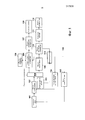
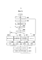
[0014] Фиг. 1 является схемой, показывающей функциональные блоки устройства 100 захвата изображений согласно первому варианту осуществления.[0014] FIG. 1 is a diagram showing functional blocks of an
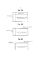
[0015] Фиг. 2A является схемой, показывающей общую конфигурацию пикселов датчика 102 изображений.[0015] FIG. 2A is a diagram showing an overall pixel configuration of an
[0016] Фиг. 2B является схемой, показывающей видеосигнал, полученный посредством подвергания видеосигнала, показанного на Фиг. 2A, обработке усреднения в вертикальной пиксельной OB-области, показанной на Фиг. 3A.[0016] FIG. 2B is a diagram showing a video signal obtained by subjecting the video signal shown in FIG. 2A, the averaging processing in the vertical pixel OB region shown in FIG. 3A.
[0017] Фиг. 2C является схемой, показывающей видеосигнал, полученный посредством дополнительного подвергания видеосигнала, показанного на Фиг. 2B, обработке усреднения в горизонтальной пиксельной OB-области.[0017] FIG. 2C is a diagram showing a video signal obtained by additionally exposing the video signal shown in FIG. 2B, averaging processing in a horizontal pixel OB region.
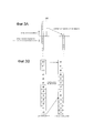
[0018] Фиг. 3A является концептуальной схемой обработки усреднения, выполняемой для одного столбца в вертикальной пиксельной OB-области.[0018] FIG. 3A is a conceptual averaging processing scheme performed for a single column in a vertical pixel OB region.
[0019] Фиг. 3B является концептуальной схемой обработки для уменьшения числа битов пикселов пиксельной OB-области.[0019] FIG. 3B is a conceptual processing diagram for reducing the number of pixel bits of a pixel OB region.
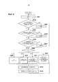
[0020] Фиг. 4 является блок-схемой последовательности операций способа, показывающей последовательность операций обработки сжатия пиксельной OB-области согласно первому варианту осуществления.[0020] FIG. 4 is a flowchart showing a flowchart of compression processing of a pixel OB region according to the first embodiment.
[0021] Фиг. 5 является блок-схемой последовательности операций способа, показывающей последовательность операций обработки сжатия пиксельной OB-области согласно второму варианту осуществления.[0021] FIG. 5 is a flowchart showing a flowchart of compression processing of a pixel OB region according to a second embodiment.
Подробное описание вариантов осуществленияDetailed Description of Embodiments
[0022] Далее описываются варианты осуществления настоящего изобретения со ссылками на прилагаемые чертежи. Следует отметить, что объем настоящего изобретения задается посредством формулы изобретения и никоим образом не ограничивается посредством вариантов осуществления, описанных ниже. Помимо этого, не все комбинации признаков, описанных в вариантах осуществления, обязательно требуются для реализации настоящего изобретения.[0022] Embodiments of the present invention will now be described with reference to the accompanying drawings. It should be noted that the scope of the present invention is defined by the claims and is in no way limited by the embodiments described below. In addition, not all combinations of features described in the embodiments are necessarily required to implement the present invention.
[0023] Первый вариант осуществления[0023] First Embodiment
Фиг. 1 является схемой, показывающей функциональные блоки устройства 100 захвата изображений согласно первому варианту осуществления. На Фиг. 1, оптическая линза 101 собирает основной свет. Оптическая линза 101 типично имеет механизм фокусировки для фокусировки, механизм диафрагмы для регулирования количества света и глубины резкости и механизм изменения масштаба для изменения фокусного расстояния. Следует отметить, что если линза является однофокусной линзой, механизм изменения масштаба не предоставляется. Кроме того, если линза является линзой с панорамирующей фокусировкой, фокус находится только в одной точке в бесконечности, и механизм фокусировки не предоставляется. Чтобы уменьшать стоимость линзы, предусмотрены случаи, когда позиция диафрагмы задается как одна позиция, и ND-фильтр для регулирования количества света используется в качестве замены. В настоящем варианте осуществления, любая оптическая линза может быть использована в качестве оптической линзы 101 при условии, что она пропускает свет для того, чтобы формировать изображение на датчике 102 изображений.FIG. 1 is a diagram showing functional blocks of an
[0024] Датчик 102 изображений принимает падающий свет из оптической линзы 101, преобразует его в электрический сигнал и выводит электрический сигнал. Типичные примеры датчика изображений включают в себя датчик изображений на основе CCD (прибора с зарядовой связью) и CMOS-датчик изображений. Датчик изображений, который непосредственно выводит аналоговый видеосигнал, может быть использован в качестве датчика 102 изображений. Альтернативно, можно использовать датчик изображений, который внутренне выполняет обработку AD (аналого-цифрового) преобразования и выводит видеосигнал в формате цифровых данных, таком как LVDS (дифференциальная передача сигналов низкого напряжения).[0024] The
[0025] Температурный датчик 103 измеряет температуру датчика 102 изображений и передает измеренную температуру в микроконтроллер 113. Разделитель 104 видеосигнала разделяет видеосигнал из датчика 102 изображений на несколько сигналов.[0025] The
[0026] Схема 105 побитового сдвига и вертикального суммирования уменьшает число пикселов в разделенном видеосигнале из разделителя 104 видеосигнала посредством выполнения при необходимости такой обработки, как побитовый сдвиг, усреднение или прореживание, в частности, для пиксельной области оптического уровня черного (OB). Усреднение выполняется посредством вертикального суммирования пикселов с использованием линейного запоминающего устройства 106, которое временно сохраняет данные строки.[0026] The bitwise shift and vertical summing
[0027] Информация, указывающая обработку сжатия сигналов (обработку для уменьшения числа пикселов), выполняемую посредством схемы 105 побитового сдвига и вертикального суммирования, присоединяется к каждому кадру в качестве метаданных посредством модуля 107 добавления метаданных. К этим метаданным обращаются, когда впоследствии выполняется обработка коррекции, которая использует данные пиксельной OB-области (например, коррекция шума с фиксированным спектром (FPN)).[0027] Information indicating signal compression processing (processing to reduce the number of pixels) performed by the bit shift and vertical summing
[0028] Носитель 108 записи записывает видеосигнал, который включает в себя данные пиксельной OB-области в качестве необработанных данных. Данные пиксельной OB-области, которые записываются, сжимаются посредством схемы 105 побитового сдвига и вертикального суммирования по мере необходимости.[0028] The
[0029] Модуль 109 сжатия видео уменьшает число пикселов в кадрах разделенного видеосигнала из разделителя 104 видеосигнала посредством выполнения обработки для выполнения суммирования для всего видеосигнала, обработки для прореживания части видеосигнала и т.п. Здесь, обработка сжатия видеосигналов (обработка для уменьшения числа пикселов) выполняется с тем, чтобы уменьшать число пикселов до величины, при которой модуль 110 коррекции изображений (описан ниже) может выполнять обработку коррекции, такую как FPN-коррекция в реальном времени.[0029] The
[0030] Модуль 110 коррекции изображений выполняет обработку коррекции, такую как FPN-коррекция в реальном времени, для сжатого видеосигнала (уменьшенных данных изображений) из модуля 109 сжатия видео. Модуль 110 коррекции изображений вычисляет значение оценки характеристик сигналов, связанных с экспозицией, фокусом, коррекцией изображений при тряске и т.п., на основе скорректированного видеосигнала и передает значение оценки в микроконтроллер 113.[0030] The
[0031] Процессор 111 проявки имеет типичные функции обработки изображений в устройстве 100 захвата изображений и выполняет различные типы обработки проявки, такие как уменьшение уровня шума, гамма-коррекция, коррекция искажений, цифровая обработка усиления и коррекция дефектов. Процессор 111 проявки включает в себя запоминающую схему для сохранения значений настроек, которые требуются в различных типах коррекции и обработки изображений.[0031] The developing
[0032] Модуль 112 отображения отображает видео, получающееся в результате обработки проявки, выполняемой посредством процессора 111 проявки. Модуль 112 отображения типично представляет собой жидкокристаллический монитор, видоискатель и т.п., присоединенный к устройству 100 захвата изображений. Пользователь устройства 100 захвата изображений может проверять угол обзора, экспозицию и т.п. с использованием модуля 112 отображения.[0032] The
[0033] Микроконтроллер 113 определяет операции оптической линзы 101, датчика 102 изображений и т.п. на основе значения оценки характеристик сигналов из модуля 110 коррекции изображений, температурной информации из температурного датчика 103 и т.п., и управляет модулем 114 управления датчиком изображений и модулем 115 управления линзами на основе определенных операций. Модуль 114 управления датчиком изображений и модуль 115 управления линзами, соответственно, управляют датчиком 102 изображений и оптической линзой 101 на основе инструкций из микроконтроллера 113.[0033] The
[0034] Далее подробно описываются операции, выполняемые посредством схемы 105 побитового сдвига и вертикального суммирования, со ссылкой на Фиг. 2A-2C и Фиг. 3A и 3B. Фиг. 2A является схемой, показывающей общую конфигурацию пикселов датчика 102 изображений. Пикселы датчика 102 изображений включают в себя эффективную пиксельную область считывания изображений, которая принимает свет из линзы и преобразует его в видеосигнал, и пиксельную область оптического уровня черного (OB), которая блокирует свет из линзы и выводит уровень черного. В частности, пиксельная OB-область, размещенная выше или ниже эффективной пиксельной области считывания изображений, называется вертикальной пиксельной OB-областью, а пиксельная OB-область, размещенная слева или справа от эффективной пиксельной области считывания изображений, называется горизонтальной пиксельной OB-областью. Эти пиксельные OB-области используются, главным образом, при горизонтальной OB-фиксации для регулирования уровня черного видеосигнала, при FPN-коррекции датчика изображений и т.п.[0034] Next, operations performed by the bit shift and vertical summing
[0035] В настоящем варианте осуществления, данные изображений записываются на носитель 108 записи без подвергания горизонтальной OB-фиксации, FPN-коррекции датчика изображений и т.п. По этой причине для надлежащей обработки и воспроизведения записанного видео впоследствии, данные из пиксельной OB-области (данные пиксельной OB-области) также должны записываться на носитель 108 записи вместе с необработанным видео, которое представляет собой необработанный видеосигнал из эффективной пиксельной области считывания изображений (данные эффективной пиксельной области считывания изображений). Тем не менее, поскольку исходное необработанное видео не подвергнуто обработке сжатия, объем данных в расчете на кадр является очень высоким. По этой причине схема 105 побитового сдвига и вертикального суммирования сжимает пиксельную OB-область в диапазоне отсутствия большого влияния на горизонтальную OB-фиксацию и FPN-коррекцию датчика изображений.[0035] In the present embodiment, image data is recorded on the
[0036] Фиг. 3A является концептуальной схемой обработки усреднения, выполняемой для одного столбца в вертикальной пиксельной OB-области. Схема 105 побитового сдвига и вертикального суммирования может усреднять пиксельную OB-область по столбцам и сжимать каждый столбец в один пиксел. Хотя не показано, аналогичное сжатие также может выполняться для горизонтальной пиксельной OB-области.[0036] FIG. 3A is a conceptual averaging processing scheme performed for a single column in a vertical pixel OB region. The bitwise shift and vertical stacking
[0037] Фиг. 2B является схемой, показывающей видеосигнал, полученный посредством подвергания видеосигнала, показанного на Фиг. 2A, обработке усреднения в вертикальной пиксельной OB-области, показанной на Фиг. 3A. На Фиг. 2B вертикальная пиксельная OB-область сжата до одной строки, и объем данных уменьшен по сравнению с Фиг. 2A.[0037] FIG. 2B is a diagram showing a video signal obtained by subjecting the video signal shown in FIG. 2A, the averaging processing in the vertical pixel OB region shown in FIG. 3A. In FIG. 2B, the vertical pixel OB region is compressed to one row, and the data volume is reduced compared to FIG. 2A.
[0038] Кроме того, Фиг. 2C является схемой, показывающей видеосигнал, полученный посредством дополнительного подвергания видеосигнала, показанного на Фиг. 2B, обработке усреднения в горизонтальной пиксельной OB-области. На Фиг. 2C горизонтальная пиксельная OB-область сжата до одного столбца, и объем данных уменьшен по сравнению с Фиг. 2B.[0038] In addition, FIG. 2C is a diagram showing a video signal obtained by additionally exposing the video signal shown in FIG. 2B, averaging processing in a horizontal pixel OB region. In FIG. 2C, the horizontal pixel OB region is compressed to one column, and the data volume is reduced compared to FIG. 2B.
[0039] Фиг. 3B является концептуальной схемой обработки для уменьшения числа битов пикселов пиксельной OB-области. Как показано на Фиг. 3B, схема 105 побитового сдвига и вертикального суммирования отсекает четыре младших бита из цифровых данных, первоначально включающих в себя 12-битовые пикселы, посредством выполнения побитового сдвига. Это позволяет получать данные, в которых каждый пиксел сжат до восьми битов. Объем данных пиксельной OB-области может быть дополнительно уменьшен посредством применения этой обработки уменьшения числа битов для видеосигналов, показанных на Фиг. 2A-2C.[0039] FIG. 3B is a conceptual processing diagram for reducing the number of pixel bits of a pixel OB region. As shown in FIG. 3B, the bit-shift and vertical-
[0040] В настоящем варианте осуществления, устройство 100 захвата изображений выполняет обработку сжатия (уменьшение объема данных) для пиксельной OB-области в диапазоне, в котором качество при обработке коррекции, которая использует пиксельную OB-область, сильно не снижается. Примеры обработки коррекции, которая использует пиксельную OB-область, включают в себя OB-фиксацию для коррекции компоненты смещения (например, изменение уровня черного) на основе данных пиксельной OB-области и FPN-коррекцию для коррекции компоненты шума (например, FPN) на основе данных пиксельной OB-области. Хотя ниже описывается только FPN-коррекция, чтобы упрощать описание, базовые идеи касательно OB-фиксации являются аналогичными базовым идеям при FPN-коррекции.[0040] In the present embodiment, the
[0041] Чтобы определять величину снижения качества при обработке коррекции, которая использует пиксельную OB-область, устройство 100 захвата изображений может использовать предварительно определенные условия захвата изображений (такие параметры, как скорость срабатывания затвора, усиление и температура датчика 102 изображений), которые влияют на целевую компоненту коррекции (изменение уровня черного или FPN). Устройство 100 захвата изображений сравнивает параметры между текущим кадром (данными изображений, полученными при захвате текущего изображения) и предыдущим кадром (данными изображений, полученными при захвате предыдущего изображения) и определяет величину, до которой должна сжиматься пиксельная OB-область согласно степени изменения параметров.[0041] In order to determine the amount of quality reduction in the correction processing that uses the pixel OB region, the
[0042] Фиг. 4 является блок-схемой последовательности операций способа, показывающей последовательность операций обработки сжатия пиксельной OB-области согласно первому варианту осуществления. Базовая идея касательно обработки сжатия состоит в том, что пиксельная OB-область сжимается тем в большей степени, чем меньше величина изменения целевой компоненты коррекции (изменение уровня черного, FPN и т.п.) относительно предыдущего кадра. В качестве одного примера в настоящем варианте осуществления, устройство 100 захвата изображений определяет величину сжатия пиксельной OB-области согласно тому, сколько из трех параметров (а именно, скорость срабатывания затвора, усиление и температура датчика 102 изображений) изменено со времени, когда захвачен предыдущий кадр. Тем не менее, критерии определения не ограничены этим и устройство 100 захвата изображений может использовать любые параметры и любые критерии при условии, что они соответствуют базовой идее, описанной выше.[0042] FIG. 4 is a flowchart showing a flowchart of compression processing of a pixel OB region according to the first embodiment. The basic idea regarding compression processing is that the pixel OB region is compressed to a greater extent, the smaller the change in the target correction component (change in black level, FPN, etc.) relative to the previous frame. As one example in the present embodiment, the
[0043] Обработка этой блок-схемы последовательности операций способа начинается, когда устройство 100 захвата изображений начинает захват видео. На этапе S401 микроконтроллер 113 инициализирует переменную N, которая служит для подсчета числа параметров, которые изменены, равной 0.[0043] The processing of this flowchart begins when the
[0044] На этапе S402 микроконтроллер 113 определяет то, изменена или нет скорость срабатывания затвора текущего кадра относительно предыдущего кадра. Если она изменена, микроконтроллер 113 прибавляет 1 к N на этапе S403. Если она не изменена, процедура пропускает этап S403 и переходит к этапу S404.[0044] In step S402, the
[0045] Скорость срабатывания затвора является временем экспонирования датчика 102 изображений, и темновой ток и т.п. датчика 102 изображений и FPN датчика 102 изображений отличаются между случаем, в котором время экспонирования составляет, например, 1/2000 секунды, и случаем, в котором оно составляет 1/2 секунды. По этой причине, если скорость срабатывания затвора изменяется, подробные данные пиксельной OB-области требуются для того, чтобы подавлять снижение качества при FPN-коррекции. Согласно блок-схеме последовательности операций способа на Фиг. 4, 1 прибавляется к N, если изменена скорость срабатывания затвора, и, как следствие, снижается величина сжатия пиксельной OB-области, и можно подавлять снижение качества при FPN-коррекции.[0045] The shutter speed is the exposure time of the
[0046] На этапе S404 микроконтроллер 113 определяет то, изменено или нет общее усиление в датчике 102 изображение и в устройстве 100 захвата изображений в текущем кадре относительно предыдущего кадра. Если изменено усиление усилителя и т.п. в датчике 102 изображений, изменяется FPN датчика 102 изображений, и, следовательно, подробные данные пиксельной OB-области требуются для того, чтобы подавлять снижение качества при FPN-коррекции. С учетом этого, если определено то, что усиление изменено, микроконтроллер 113 прибавляет 1 к N на этапе S405. Если усиление не изменено, процедура пропускает этап S405 и переходит к этапу S406.[0046] In step S404, the
[0047] На этапе S406 микроконтроллер 113 определяет то, изменена или нет температура датчика 102 изображений во время захвата текущего кадра относительно температуры во время захвата предыдущего кадра. Если температура изменяется, изменяется темновой ток и т.п. датчика 102 изображений, и изменяется FPN датчика 102 изображений, и, следовательно, подробные данные пиксельной OB-области требуются для того, чтобы подавлять снижение качества при FPN-коррекции. С учетом этого, если определено то, что температура изменена, микроконтроллер 113 прибавляет 1 к N на этапе S407. Если температура не изменена, процедура пропускает этап S407 и переходит к этапу S408.[0047] In step S406, the
[0048] Следует отметить, что пороговое значение может быть использовано для того, чтобы определять то, изменяется или нет параметр на некоторых или всех этапах S402, S404 и S406. Например, на этапе S404, микроконтроллер 113 может определять то, что усиление изменено, если изменение усиления превышает или равно пороговому значению Δy (дБ: децибел), и определять то, что усиление не изменено, если изменение усиления меньше Δy (дБ). Значение порогового значения Δy (дБ) является значением, уникальным для устройства 100 захвата изображений, и определяется на основе абсолютной величины FPN включенного датчика 102 изображений. Альтернативно, если усиление усилителя и т.п. в датчике 102 изображений изменено, микроконтроллер 113 может определять то, что усиление изменено независимо от значения Δy (дБ). В другом примере, на этапе S406, микроконтроллер 113 может определять то, что температура изменена, если изменение температуры превышает или равно пороговому значению Δz, и определять то, что температура не изменена, если изменение температуры меньше Δz. Значение порогового значения Δz является значением, уникальным для устройства 100 захвата изображений, и определяется на основе абсолютной величины темнового тока включенного датчика 102 изображений.[0048] It should be noted that the threshold value may be used to determine whether or not the parameter is changed in some or all of the steps S402, S404, and S406. For example, in step S404, the
[0049] На этапе S408 микроконтроллер 113 переходит к одной из нескольких ветвей обработки согласно значению переменной N. В частности, если N=3, на этапе S409 микроконтроллер 113 инструктирует схеме 105 побитового сдвига и вертикального суммирования не сжимать данные пиксельной OB-области. Если N=2, на этапе S410 микроконтроллер 113 инструктирует схеме 105 побитового сдвига и вертикального суммирования усреднять вертикальную пиксельную OB-область, как показано на Фиг. 2B. Если N=1, на этапе S411 микроконтроллер 113 инструктирует схеме 105 побитового сдвига и вертикального суммирования усреднять вертикальную пиксельную OB-область и горизонтальную пиксельную OB-область, как показано на Фиг. 2C. Если N=0, на этапе S412 микроконтроллер 113 инструктирует схеме 105 побитового сдвига и вертикального суммирования усреднять вертикальную пиксельную OB-область и горизонтальную пиксельную OB-область, как показано на Фиг. 2C, и затем уменьшать число битов, как показано на Фиг. 3B.[0049] In step S408, the
[0050] Следует отметить, что способ сжатия данных пиксельной OB-области не ограничивается способом, показанным на Фиг. 2B, 2C и 3B. Например, данные пиксельной OB-области могут сжиматься посредством выполнения усреднения для пикселов в пиксельной OB-области в единицах двух пикселов.[0050] It should be noted that the data compression method of the pixel OB region is not limited to the method shown in FIG. 2B, 2C and 3B. For example, pixel OB region data may be compressed by performing averaging for pixels in the pixel OB region in units of two pixels.
[0051] На этапе S413 информация, указывающая обработку сжатия, выполняемую посредством схемы 105 побитового сдвига и вертикального суммирования (информация, указывающая то, как сжаты данные пиксельной OB-области), добавляется в видеосигнал в качестве метаданных посредством модуля 107 добавления метаданных. Причина этого состоит в том, что число пикселов и объем данных в расчете на кадр изменяются, когда FPN-коррекция выполняется впоследствии, и, следовательно, невозможно надлежащим образом выполнять FPN-коррекцию, пока состояние сжатия данных пиксельной OB-области не записано.[0051] In step S413, information indicating the compression processing performed by the bit shift and vertical summing circuit 105 (information indicating how the pixel OB region data is compressed) is added to the video signal as metadata by the
[0052] На этапе S414 устройство 100 захвата изображений записывает данные текущего кадра на носитель 108 записи вместе с метаданными. Процедура затем переходит к этапу S401, и аналогичная обработка повторяется для следующего кадра.[0052] In step S414, the
[0053] Как описано выше, согласно первому варианту осуществления, устройство 100 захвата изображений сжимает пиксельную OB-область согласно степени, в которой целевая компонента коррекции, которая должна быть скорректирована на основе данных пиксельной OB-области (компонента смещения или компонента шума), изменена относительно предыдущего кадра. В частности, устройство 100 захвата изображений сжимает пиксельную OB-область, если степень изменения меньше или равна пороговому значению (в примере на Фиг. 4, в случае, в котором N=2, 1 или 0), и не сжимает пиксельную OB-область в ином случае (в примере на Фиг. 4, в случае, в котором N=3). Кроме того, в случае, если пиксельная OB-область сжимается, устройство 100 захвата изображений сжимает данные пиксельной OB-области тем в большей степени, чем меньше величина изменения целевой компоненты коррекции относительно предыдущего кадра.[0053] As described above, according to the first embodiment, the
[0054] Соответственно, в случае, если обработка коррекции, которая использует данные пиксельной OB-области, выполняется после записи данных изображений, можно уменьшать объем данных пиксельной OB-области, который записывается, при одновременном подавлении снижения качества при обработке коррекции.[0054] Accordingly, in the event that correction processing that uses pixel OB region data is performed after recording image data, it is possible to reduce the amount of pixel OB region data that is recorded while suppressing a quality reduction in the correction processing.
[0055] Модификации[0055] Modifications
На блок-схеме последовательности операций способа по Фиг. 4, устройство 100 захвата изображений определяет степень изменения целевой компоненты коррекции относительно предыдущего кадра на основе изменения условия захвата изображений, которое вносит вклад в формирование целевой компоненты коррекции (такого параметра, как скорость срабатывания затвора) относительно предыдущего кадра. Напротив, в модификации, описанной ниже, степень изменения целевой компоненты коррекции, включенной в полноразмерные данные изображений относительно предыдущего кадра, определяется на основе целевой компоненты коррекции, включенной в уменьшенные данные изображений, сформированные посредством модуля 109 сжатия видео.In the flowchart of FIG. 4, the
[0056] В частности, в сочетании с обработкой коррекции, выполняемой для уменьшенных данных изображений, модуль 110 коррекции изображений обнаруживает целевую компоненту коррекции, включенную в уменьшенные данные изображений, и уведомляет микроконтроллер 113 относительно обнаруженной целевой компоненты коррекции. Микроконтроллер 113 определяет степень изменения целевой компоненты коррекции, включенной в уменьшенные данные изображений, посредством сравнения сообщенной целевой компоненты коррекции с целевой компонентой коррекции, включенной в уменьшенные данные изображений предыдущего кадра. Считается, что изменение целевой компоненты коррекции, включенной в полноразмерные данные изображений, примерно соответствует изменению целевой компоненты коррекции, включенной в уменьшенные данные изображений. С учетом этого, на основе степени изменения целевой компоненты коррекции, включенной в уменьшенные данные изображений, микроконтроллер 113 инструктирует схеме 105 побитового сдвига и вертикального суммирования уменьшать объем данных пиксельной OB-области в большей степени, чем меньше степень изменения.[0056] In particular, in combination with the correction processing performed for the reduced image data, the
[0057] Второй вариант осуществления[0057] Second Embodiment
Во втором варианте осуществления описывается конфигурация, в которой удаляются данные пиксельной OB-области, чтобы значительно уменьшать объем данных пиксельной OB-области. Кроме того, в конфигурации, описанной ниже, в случае, если пиксельная OB-область сжата в нескольких кадрах, полученных посредством многократного выполнения захвата изображений последовательно, пиксельная OB-область не сжимается в кадре, полученном в следующем случае захвата изображений, независимо от степени изменения целевой компоненты коррекции. В настоящем варианте осуществления, базовая конфигурация устройства 100 захвата изображений является аналогичной базовой конфигурации в первом варианте осуществления (см. Фиг. 1).In a second embodiment, a configuration is described in which pixel OB region data is deleted to significantly reduce the data volume of the pixel OB region. In addition, in the configuration described below, if the pixel OB region is compressed in several frames obtained by repeatedly capturing images in series, the pixel OB region is not compressed in the frame obtained in the following image capture case, regardless of the degree of change target correction components. In the present embodiment, the basic configuration of the
[0058] Фиг. 5 является блок-схемой последовательности операций способа, показывающей последовательность операций обработки сжатия пиксельной OB-области согласно второму варианту осуществления. Этапам на этой блок-схеме последовательности операций способа, которые служат для выполнения обработки, идентичной или аналогичной этапам на Фиг. 4, присвоены идентичные ссылки с номерами, и эти этапы не описываются.[0058] FIG. 5 is a flowchart showing a flowchart of compression processing of a pixel OB region according to a second embodiment. The steps in this flowchart that serve to perform processing identical to or similar to the steps in FIG. 4, identical reference numbers are assigned, and these steps are not described.
[0059] На этапе S501, микроконтроллер 113 инициализирует переменную M, которая служит для подсчета числа последовательных кадров, в которых пиксельная OB-область сжата, равной 0.[0059] In step S501, the
[0060] На этапе S502 микроконтроллер 113 определяет то, превышает или равно либо нет M пороговому значению Th. Если оно превышает или равно пороговому значению, процедура переходит к этапу S409, в котором микроконтроллер 113 инструктирует схеме 105 побитового сдвига и вертикального суммирования не сжимать данные пиксельной OB-области. Таким образом, если сжатие пиксельной OB-области продолжается для числа кадров, превышающего или равного пороговому значению, определение этапа S408 не выполняется, и данные пиксельной OB-области не сжимаются независимо от того, изменено или нет условие захвата изображений. Следует отметить, что если датчик 102 изображений приводится в действие при 60 кадрах/с, пороговое значение Th задается равным, например, 60. В этом случае, кадр, имеющий записанной всю пиксельную OB-область, всегда создается однократно каждую секунду.[0060] In step S502, the
[0061] Если N=0 на этапе S408, процедура переходит к этапу S503, на котором микроконтроллер 113 инструктирует схеме 105 побитового сдвига и вертикального суммирования удалять пиксельную OB-область. Таким образом, в настоящем варианте осуществления, если изменение условия захвата изображений является очень небольшим (т.е. если изменение целевой компоненты коррекции является очень небольшим), пиксельная OB-область удаляется вместо сжатия.[0061] If N = 0 in step S408, the procedure proceeds to step S503, in which the
[0062] В случае, если данные пиксельной OB-области не должны сжиматься, процедура переходит к этапу S504, на котором микроконтроллер 113 инициализирует переменную M равной 0. С другой стороны, в случае, если данные пиксельной OB-области должны сжиматься или удаляться, процедура переходит к этапу S505, S506 или S507, на котором микроконтроллер 113 прибавляет 1 к переменной M.[0062] If the data of the pixel OB region should not be compressed, the procedure proceeds to step S504, in which the
[0063] Как описано выше, согласно второму варианту осуществления, если N=0 на этапе S408 (т.е. если изменение условия захвата изображений является очень небольшим), устройство 100 захвата изображений удаляет данные пиксельной OB-области перед записью данных изображений. Кроме того, если пиксельная OB-область сжата в нескольких кадрах, полученных посредством многократного выполнения захвата изображений последовательно, устройство 100 захвата изображений не сжимает пиксельную OB-область в кадре, полученном в следующем случае захвата изображений, независимо от степени изменения целевой компоненты коррекции. Это позволяет значительно уменьшать объем данных пиксельной OB-области и подавлять снижение качества при обработке коррекции.[0063] As described above, according to the second embodiment, if N = 0 in step S408 (ie, if the change in the image capturing condition is very small), the
[0064] Другие варианты осуществления[0064] Other embodiments
Варианты осуществления настоящего изобретения также могут быть реализованы посредством компьютера системы или устройства, которое считывает и выполняет машиноисполняемые инструкции, записанные на носителе хранения данных (например, на энергонезависимом машиночитаемом носителе хранения данных), чтобы выполнять функции одного или более вышеописанных вариантов осуществления настоящего изобретения, и посредством способа, осуществляемого посредством компьютера системы или устройства, например, посредством считывания и выполнения машиноисполняемых инструкций из носителя хранения данных, чтобы выполнять функции одного или более вышеописанных вариантов осуществления. Компьютер может содержать одно или более из центрального процессора (CPU), микропроцессора (MPU) или другой схемы и может включать в себя сеть отдельных компьютеров или отдельных процессоров компьютера. Машиноисполняемые инструкции могут предоставляться в компьютер, например, из сети или носителя хранения данных. Носитель хранения данных может включать в себя, например, одно или более жесткого диска, оперативного запоминающего устройства (RAM), постоянного запоминающего устройства (ROM), устройства хранения распределенных вычислительных систем, оптического диска (такого как компакт-диск (CD), универсальный цифровой диск (DVD) или Blu-Ray-диск (BD)™), устройства флэш-памяти, карты памяти и т.п.Embodiments of the present invention may also be implemented by a computer system or device that reads and executes computer-executable instructions recorded on a storage medium (e.g., non-volatile computer-readable storage medium) to perform the functions of one or more of the above-described embodiments of the present invention, and by a method implemented by a computer system or device, for example, by reading and executing a machine executable instructions from the storage medium to perform the functions of one or more of the above embodiments. A computer may comprise one or more of a central processing unit (CPU), microprocessor (MPU), or other circuitry, and may include a network of individual computers or individual computer processors. Computer-executable instructions may be provided to a computer, for example, from a network or storage medium. A storage medium may include, for example, one or more hard drives, random access memory (RAM), read-only memory (ROM), storage devices for distributed computing systems, an optical disk (such as a compact disc (CD), universal digital a disc (DVD) or a Blu-ray disc (BD) ™), flash memory devices, memory cards, etc.
[0065] Хотя настоящее изобретение описано со ссылкой на примерные варианты осуществления, следует понимать, что изобретение не ограничено раскрытыми примерными вариантами осуществления. Объем нижеследующей формулы изобретения должен соответствовать самой широкой интерпретации, так что он заключает в себе все такие модификации и эквивалентные структуры и функции.[0065] Although the present invention has been described with reference to exemplary embodiments, it should be understood that the invention is not limited to the disclosed exemplary embodiments. The scope of the following claims should be accorded the broadest interpretation so that it encompasses all such modifications and equivalent structures and functions.
Claims (19)
Applications Claiming Priority (2)
| Application Number | Priority Date | Filing Date | Title |
|---|---|---|---|
| JP2013-193490 | 2013-09-18 | ||
| JP2013193490A JP6271926B2 (en) | 2013-09-18 | 2013-09-18 | Imaging device, control method thereof, and program |
Publications (2)
| Publication Number | Publication Date |
|---|---|
| RU2014137122A RU2014137122A (en) | 2016-04-10 |
| RU2619721C2 true RU2619721C2 (en) | 2017-05-17 |
Family
ID=52580041
Family Applications (1)
| Application Number | Title | Priority Date | Filing Date |
|---|---|---|---|
| RU2014137122A RU2619721C2 (en) | 2013-09-18 | 2014-09-12 | Image capture device, image capture system and control method for image capture device |
Country Status (5)
| Country | Link |
|---|---|
| US (1) | US9721609B2 (en) |
| JP (1) | JP6271926B2 (en) |
| CN (1) | CN104469186B (en) |
| DE (1) | DE102014013446A1 (en) |
| RU (1) | RU2619721C2 (en) |
Families Citing this family (11)
| Publication number | Priority date | Publication date | Assignee | Title |
|---|---|---|---|---|
| KR102443218B1 (en) * | 2016-01-06 | 2022-09-15 | 삼성전자주식회사 | Electronic apparatus and operating method thereof |
| JP2017143340A (en) * | 2016-02-08 | 2017-08-17 | 株式会社デンソー | Information processing apparatus and program |
| JP2018006785A (en) * | 2016-06-27 | 2018-01-11 | ソニーセミコンダクタソリューションズ株式会社 | Signal processing apparatus, imaging apparatus, and signal processing method |
| US10721426B2 (en) * | 2017-08-31 | 2020-07-21 | Canon Kabushiki Kaisha | Solid-state image sensor, image capture apparatus and image capture method |
| DE102018203969A1 (en) * | 2018-03-15 | 2019-09-19 | Conti Temic Microelectronic Gmbh | Automobile camera with raw image signal interface |
| JP7146424B2 (en) | 2018-03-19 | 2022-10-04 | キヤノン株式会社 | Photoelectric conversion device and imaging system |
| US20190356877A1 (en) * | 2018-05-17 | 2019-11-21 | Sony Semiconductor Solutions Corporation | Image sensor with s/h-to-adc voltage range matching |
| JP7114412B2 (en) | 2018-09-04 | 2022-08-08 | キヤノン株式会社 | LENS DEVICE AND CAMERA SYSTEM INCLUDING THE SAME |
| JP7321686B2 (en) | 2018-09-04 | 2023-08-07 | キヤノン株式会社 | LENS DEVICE AND CAMERA SYSTEM INCLUDING THE SAME |
| CN110365922B (en) * | 2019-07-03 | 2021-09-14 | 成都微光集电科技有限公司 | Black level correction method of image sensor |
| CN110365925B (en) * | 2019-07-11 | 2021-08-31 | 北京安酷智芯科技有限公司 | Reading circuit, and method and device for determining bias circuit noise |
Citations (5)
| Publication number | Priority date | Publication date | Assignee | Title |
|---|---|---|---|---|
| JP2010200109A (en) * | 2009-02-26 | 2010-09-09 | Canon Inc | Imaging device, control method, and program |
| US20100231761A1 (en) * | 2009-03-16 | 2010-09-16 | Canon Kabushiki Kaisha | Image sensor and image capturing apparatus |
| US20110310269A1 (en) * | 2010-06-16 | 2011-12-22 | Seiko Epson Corporation | Image-capturing device and timing control circuit |
| RU2463663C2 (en) * | 2007-05-31 | 2012-10-10 | Панасоник Корпорэйшн | Image capturing apparatus, additional information providing and additional information filtering system |
| WO2013024659A1 (en) * | 2011-08-15 | 2013-02-21 | Canon Kabushiki Kaisha | Image capturing apparatus, method of controlling the same and program |
Family Cites Families (12)
| Publication number | Priority date | Publication date | Assignee | Title |
|---|---|---|---|---|
| JPH11112885A (en) * | 1997-10-03 | 1999-04-23 | Olympus Optical Co Ltd | Camera |
| JP2005175930A (en) | 2003-12-11 | 2005-06-30 | Canon Inc | Image pickup device, its signal processing method, and image pickup system |
| US7750955B2 (en) | 2004-08-31 | 2010-07-06 | Canon Kabushiki Kaisha | Image signal processing apparatus, image signal processing method and camera using the image signal processing apparatus |
| JP2006115078A (en) | 2004-10-13 | 2006-04-27 | Matsushita Electric Ind Co Ltd | Device and method for signal processing of image data |
| JP4625685B2 (en) | 2004-11-26 | 2011-02-02 | 株式会社東芝 | Solid-state imaging device |
| JP4351658B2 (en) | 2005-07-21 | 2009-10-28 | マイクロン テクノロジー, インク. | Memory capacity reduction method, memory capacity reduction noise reduction circuit, and memory capacity reduction device |
| JP2007300282A (en) | 2006-04-28 | 2007-11-15 | Sony Corp | Imaging apparatus, image processing method, and computer/program |
| JP4385060B2 (en) * | 2007-05-16 | 2009-12-16 | シャープ株式会社 | Solid-state imaging device and electronic information device |
| JP2009017459A (en) | 2007-07-09 | 2009-01-22 | Fujifilm Corp | Ccd solid-state imaging element, driving method thereof, and imaging apparatus |
| JP5231284B2 (en) * | 2008-03-31 | 2013-07-10 | 富士フイルム株式会社 | Imaging apparatus, imaging method, and program |
| JP5126346B2 (en) | 2010-11-24 | 2013-01-23 | カシオ計算機株式会社 | Imaging apparatus, image processing method, and program |
| JP5871496B2 (en) | 2011-06-24 | 2016-03-01 | キヤノン株式会社 | Imaging apparatus and driving method thereof |
-
2013
- 2013-09-18 JP JP2013193490A patent/JP6271926B2/en not_active Expired - Fee Related
-
2014
- 2014-09-11 US US14/483,429 patent/US9721609B2/en not_active Expired - Fee Related
- 2014-09-12 RU RU2014137122A patent/RU2619721C2/en active
- 2014-09-12 DE DE201410013446 patent/DE102014013446A1/en not_active Withdrawn
- 2014-09-16 CN CN201410471892.3A patent/CN104469186B/en not_active Expired - Fee Related
Patent Citations (5)
| Publication number | Priority date | Publication date | Assignee | Title |
|---|---|---|---|---|
| RU2463663C2 (en) * | 2007-05-31 | 2012-10-10 | Панасоник Корпорэйшн | Image capturing apparatus, additional information providing and additional information filtering system |
| JP2010200109A (en) * | 2009-02-26 | 2010-09-09 | Canon Inc | Imaging device, control method, and program |
| US20100231761A1 (en) * | 2009-03-16 | 2010-09-16 | Canon Kabushiki Kaisha | Image sensor and image capturing apparatus |
| US20110310269A1 (en) * | 2010-06-16 | 2011-12-22 | Seiko Epson Corporation | Image-capturing device and timing control circuit |
| WO2013024659A1 (en) * | 2011-08-15 | 2013-02-21 | Canon Kabushiki Kaisha | Image capturing apparatus, method of controlling the same and program |
Also Published As
| Publication number | Publication date |
|---|---|
| DE102014013446A1 (en) | 2015-03-19 |
| JP6271926B2 (en) | 2018-01-31 |
| US20150078725A1 (en) | 2015-03-19 |
| JP2015061199A (en) | 2015-03-30 |
| RU2014137122A (en) | 2016-04-10 |
| US9721609B2 (en) | 2017-08-01 |
| CN104469186A (en) | 2015-03-25 |
| CN104469186B (en) | 2017-10-24 |
Similar Documents
| Publication | Publication Date | Title |
|---|---|---|
| RU2619721C2 (en) | Image capture device, image capture system and control method for image capture device | |
| US9635289B2 (en) | Image capturing apparatus, control method thereof, and storage medium | |
| JP5746521B2 (en) | IMAGING DEVICE, ITS CONTROL METHOD, PROGRAM, AND STORAGE MEDIUM | |
| JP2010147816A (en) | Imaging apparatus and control method thereof | |
| KR102229152B1 (en) | Image photographing appratus | |
| US20170310878A1 (en) | Image capturing apparatus and control method thereof | |
| US20170257591A1 (en) | Signal processing apparatus, image capturing apparatus, control apparatus, signal processing method, and control method | |
| KR20100096523A (en) | Apparatus and method for processing image data | |
| JP4985220B2 (en) | Image processing apparatus, camera, image processing program, and image processing method | |
| US9900533B2 (en) | Image processing apparatus and method, and image capturing apparatus | |
| JP2008109504A (en) | Imaging device and correcting method | |
| JP2013219665A (en) | Imaging device, control method therefor, and program | |
| CN103581578A (en) | Image pickup apparatus and image pickup method | |
| US20190387172A1 (en) | Image capturing apparatus, method of controlling same, and storage medium | |
| JP2010130238A (en) | Defect correcting circuit and imaging device with same | |
| US9282245B2 (en) | Image capturing apparatus and method of controlling the same | |
| US10397587B2 (en) | Image processing apparatus and control method thereof | |
| US10205870B2 (en) | Image capturing apparatus and control method thereof | |
| US10178342B2 (en) | Imaging system, imaging apparatus, and control method for controlling the same | |
| JP2011166422A (en) | Imaging apparatus | |
| US10015362B2 (en) | Image capturing apparatus for resizing raw image data and control method thereof | |
| JP2014107739A (en) | Imaging device and control method therefor | |
| JP2015216601A (en) | Imaging device, control method for the same and program | |
| JP2010050730A (en) | Imaging apparatus and defect correction apparatus | |
| JP2008072512A (en) | Photographing apparatus and its control method, and photographing system |