RU2619048C2 - Heater and containing its image heating device - Google Patents
Heater and containing its image heating device Download PDFInfo
- Publication number
- RU2619048C2 RU2619048C2 RU2015119674A RU2015119674A RU2619048C2 RU 2619048 C2 RU2619048 C2 RU 2619048C2 RU 2015119674 A RU2015119674 A RU 2015119674A RU 2015119674 A RU2015119674 A RU 2015119674A RU 2619048 C2 RU2619048 C2 RU 2619048C2
- Authority
- RU
- Russia
- Prior art keywords
- substrate
- electrode
- heater
- contact
- electrical contacts
- Prior art date
Links
Images

Classifications
-
- H—ELECTRICITY
- H05—ELECTRIC TECHNIQUES NOT OTHERWISE PROVIDED FOR
- H05B—ELECTRIC HEATING; ELECTRIC LIGHT SOURCES NOT OTHERWISE PROVIDED FOR; CIRCUIT ARRANGEMENTS FOR ELECTRIC LIGHT SOURCES, IN GENERAL
- H05B3/00—Ohmic-resistance heating
- H05B3/0014—Devices wherein the heating current flows through particular resistances
-
- H—ELECTRICITY
- H05—ELECTRIC TECHNIQUES NOT OTHERWISE PROVIDED FOR
- H05B—ELECTRIC HEATING; ELECTRIC LIGHT SOURCES NOT OTHERWISE PROVIDED FOR; CIRCUIT ARRANGEMENTS FOR ELECTRIC LIGHT SOURCES, IN GENERAL
- H05B3/00—Ohmic-resistance heating
-
- G—PHYSICS
- G03—PHOTOGRAPHY; CINEMATOGRAPHY; ANALOGOUS TECHNIQUES USING WAVES OTHER THAN OPTICAL WAVES; ELECTROGRAPHY; HOLOGRAPHY
- G03G—ELECTROGRAPHY; ELECTROPHOTOGRAPHY; MAGNETOGRAPHY
- G03G15/00—Apparatus for electrographic processes using a charge pattern
- G03G15/20—Apparatus for electrographic processes using a charge pattern for fixing, e.g. by using heat
- G03G15/2003—Apparatus for electrographic processes using a charge pattern for fixing, e.g. by using heat using heat
- G03G15/2014—Apparatus for electrographic processes using a charge pattern for fixing, e.g. by using heat using heat using contact heat
- G03G15/2039—Apparatus for electrographic processes using a charge pattern for fixing, e.g. by using heat using heat using contact heat with means for controlling the fixing temperature
- G03G15/2042—Apparatus for electrographic processes using a charge pattern for fixing, e.g. by using heat using heat using contact heat with means for controlling the fixing temperature specially for the axial heat partition
-
- G—PHYSICS
- G03—PHOTOGRAPHY; CINEMATOGRAPHY; ANALOGOUS TECHNIQUES USING WAVES OTHER THAN OPTICAL WAVES; ELECTROGRAPHY; HOLOGRAPHY
- G03G—ELECTROGRAPHY; ELECTROPHOTOGRAPHY; MAGNETOGRAPHY
- G03G15/00—Apparatus for electrographic processes using a charge pattern
- G03G15/20—Apparatus for electrographic processes using a charge pattern for fixing, e.g. by using heat
- G03G15/2003—Apparatus for electrographic processes using a charge pattern for fixing, e.g. by using heat using heat
- G03G15/2014—Apparatus for electrographic processes using a charge pattern for fixing, e.g. by using heat using heat using contact heat
- G03G15/2053—Structural details of heat elements, e.g. structure of roller or belt, eddy current, induction heating
-
- H—ELECTRICITY
- H05—ELECTRIC TECHNIQUES NOT OTHERWISE PROVIDED FOR
- H05B—ELECTRIC HEATING; ELECTRIC LIGHT SOURCES NOT OTHERWISE PROVIDED FOR; CIRCUIT ARRANGEMENTS FOR ELECTRIC LIGHT SOURCES, IN GENERAL
- H05B3/00—Ohmic-resistance heating
- H05B3/02—Details
- H05B3/03—Electrodes
-
- H—ELECTRICITY
- H05—ELECTRIC TECHNIQUES NOT OTHERWISE PROVIDED FOR
- H05B—ELECTRIC HEATING; ELECTRIC LIGHT SOURCES NOT OTHERWISE PROVIDED FOR; CIRCUIT ARRANGEMENTS FOR ELECTRIC LIGHT SOURCES, IN GENERAL
- H05B3/00—Ohmic-resistance heating
- H05B3/02—Details
- H05B3/06—Heater elements structurally combined with coupling elements or holders
-
- G—PHYSICS
- G03—PHOTOGRAPHY; CINEMATOGRAPHY; ANALOGOUS TECHNIQUES USING WAVES OTHER THAN OPTICAL WAVES; ELECTROGRAPHY; HOLOGRAPHY
- G03G—ELECTROGRAPHY; ELECTROPHOTOGRAPHY; MAGNETOGRAPHY
- G03G2215/00—Apparatus for electrophotographic processes
- G03G2215/20—Details of the fixing device or porcess
- G03G2215/2003—Structural features of the fixing device
- G03G2215/2016—Heating belt
- G03G2215/2035—Heating belt the fixing nip having a stationary belt support member opposing a pressure member
Landscapes
- Physics & Mathematics (AREA)
- General Physics & Mathematics (AREA)
- Fixing For Electrophotography (AREA)
- Resistance Heating (AREA)
- Control Of Resistance Heating (AREA)
- Control Or Security For Electrophotography (AREA)
Abstract
Description
Область техники, к которой относится изобретение и уровень техникиFIELD OF THE INVENTION
[0001] Известно устройство формирования изображений, в котором проявленное тонером изображение формируется на листе и закрепляется на листе посредством нагревания и давления в устройстве закрепления. Что касается такого устройства закрепления, предложен тип устройства закрепления (выложенная заявка на патент Японии Hei 6-250539), в котором теплогенерирующий элемент (нагреватель) контактирует с внутренней поверхностью тонкой гибкой ленты, чтобы приложить тепло к ленте. Такое устройство закрепления имеет преимущество в том, что конструкция имеет низкую теплоемкость, и, таким образом, обеспечивается быстрое повышение температуры при операции закрепления.[0001] An image forming apparatus is known in which a toner image is formed on a sheet and fixed to the sheet by heating and pressure in the fixing device. With regard to such a fixing device, a type of fixing device is proposed (Japanese Patent Application Laid-Open Hei 6-250539) in which a heat generating element (heater) contacts the inner surface of a thin flexible tape to apply heat to the tape. Such a fixing device has the advantage that the structure has a low heat capacity, and thus, a rapid temperature increase during the fixing operation is provided.
[0002] Нагреватель, раскрытый в выложенной заявке на патент Японии Hei 6-250539, содержит множество электродов, расположенных в продольном направлении подложки, для соединения с теплогенерирующим элементом, простирающимся в продольном направлении упомянутой подложки. Электроды, имеющие разные полярности, размещены попеременно, так что электрические токи текут через теплогенерирующий элемент между смежными электродами. Более конкретно, электрод, имеющий одну из полярностей, соединен с электропроводной линией, обеспеченной на одной стороне оконечного участка подложки вне теплогенерирующего элемента относительно направления по ширине, а электрод, имеющий другую из полярностей, соединен с электропроводной линией, обеспеченной на другой стороне оконечного участка подложки вне теплогенерирующего элемента относительно направления по ширине. Таким образом, когда между электропроводными линиями подано напряжение, теплогенерирующий элемент генерирует тепло во всей продольной области.[0002] The heater disclosed in Japanese Patent Application Laid-open Hei 6-250539 comprises a plurality of electrodes arranged in the longitudinal direction of the substrate for connecting to a heat generating element extending in the longitudinal direction of said substrate. Electrodes having different polarities are arranged alternately, so that electric currents flow through a heat generating element between adjacent electrodes. More specifically, an electrode having one of the polarities is connected to a conductive line provided on one side of the terminal portion of the substrate outside the heat generating element with respect to the width direction, and an electrode having the other of polarities is connected to a conductive line provided on the other side of the terminal portion of the substrate outside the heat generating element relative to the width direction. Thus, when voltage is applied between the electrical conductive lines, the heat generating element generates heat in the entire longitudinal region.
[0003] Однако устройство закрепления, раскрытое в выложенной заявке на патент Японии Hei 6-250539, имеет момент, который следует улучшить относительно неоднородности генерации тепла теплогенерирующего элемента. Как описано выше, в устройстве закрепления напряжение подают между электропроводными линиями с одной стороны оконечного участка нагревателя относительно продольного направления. Однако электропроводные линии имеют некоторые сопротивления, и, таким образом, напряжение, поданное между электропроводными линиями, уменьшается по направлению к другой стороне оконечного участка подложки. Таким образом, количество сгенерированного тепла ниже на другой стороне оконечного участка, чем на одной стороне оконечного участка теплогенерирующего элемента. Когда в устройстве закрепления используется нагреватель, закрепленное изображение тем самым включает в себя дефект изображения, такой как неравномерность глянца. Таким образом, желательно обеспечить нагреватель, с помощью которого может быть предотвращена неоднородность генерации тепла.[0003] However, the fixing device disclosed in Japanese Patent Application Laid-Open Hei 6-250539 has a point that should be improved regarding the heterogeneity of heat generation of the heat generating element. As described above, in the clamping device, a voltage is applied between the conductive lines on one side of the end portion of the heater relative to the longitudinal direction. However, the conductive lines have some resistances, and thus, the voltage applied between the conductive lines decreases towards the other side of the terminal portion of the substrate. Thus, the amount of heat generated is lower on the other side of the terminal portion than on one side of the terminal portion of the heat generating element. When a heater is used in the fixing device, the fixed image thereby includes an image defect, such as gloss unevenness. Thus, it is desirable to provide a heater with which heat generation heterogeneity can be prevented.
Сущность изобретенияSUMMARY OF THE INVENTION
[0004] Задача настоящего изобретения состоит в обеспечении нагревателя, с которым предотвращается неоднородность генерации тепла.[0004] An object of the present invention is to provide a heater with which heterogeneity of heat generation is prevented.
[0005] Другая задача настоящего изобретения состоит в обеспечении устройства нагревания изображения, с которым предотвращается неоднородность генерации тепла.[0005] Another object of the present invention is to provide an image heating apparatus with which heat generation heterogeneity is prevented.
[0006] В соответствии с аспектом настоящего изобретения обеспечен нагреватель, применимый с устройством нагревания изображения, включающим в себя участок подачи электроэнергии, снабженный первой клеммой и второй клеммой и бесконечной лентой для нагревания изображения на листе, причем упомянутый нагреватель соединяется с лентой для нагревания этой ленты и содержит подложку; множество контактных участков, включающее в себя по меньшей мере один первый контактный участок, обеспеченный на упомянутой подложке и электрически соединяемый с первой клеммой, и множество вторых контактных участков, обеспеченных на упомянутой подложке и электрически соединяемых со второй клеммой; множество электродных участков, размещенных в продольном направлении упомянутой подложки с заданными промежутками; множество участков электропроводных линий, электрически соединяющих упомянутые электродные участки с соответствующими упомянутыми контактными участками, так что упомянутый электродный участок, электрически соединенный с упомянутым первым контактным участком, и упомянутый электродный участок, электрически соединенный с упомянутыми вторыми контактными участками, размещены поочередно в продольном направлении упомянутой подложки; и множество теплогенерирующих участков, обеспеченных между смежными электродными участками, соответственно, для генерации тепла посредством снабжения электрической энергией между смежными электродными участками, причем все упомянутые первые контактные участки обеспечены на одной стороне оконечного участка упомянутой подложки относительно продольного направления, и все упомянутые вторые контактные участки обеспечены на другой стороне оконечного участка упомянутой подложки относительно продольного направления.[0006] In accordance with an aspect of the present invention, there is provided a heater applicable to an image heating apparatus including an electric power supply portion provided with a first terminal and a second terminal and an endless tape for heating an image on a sheet, said heater connecting to a tape for heating this tape and contains a substrate; a plurality of contact portions including at least one first contact portion provided on said substrate and electrically connected to the first terminal, and a plurality of second contact portions provided on said substrate and electrically connected to the second terminal; a plurality of electrode portions arranged in a longitudinal direction of said substrate at predetermined intervals; a plurality of sections of electrical conductive lines electrically connecting said electrode sections to respective said contact sections, such that said electrode section electrically connected to said first contact section and said electrode section electrically connected to said second contact sections are alternately arranged in a longitudinal direction of said substrate ; and a plurality of heat generating sections provided between adjacent electrode sections, respectively, for generating heat by supplying electrical energy between adjacent electrode sections, wherein all said first contact sections are provided on one side of an end section of said substrate with respect to a longitudinal direction, and all said second contact sections are provided on the other side of the terminal portion of said substrate with respect to the longitudinal direction.
[0007] Дополнительные признаки настоящего изобретения станут очевидны из следующего описания иллюстративных вариантов осуществления со ссылкой на приложенные чертежи.[0007] Further features of the present invention will become apparent from the following description of illustrative embodiments with reference to the attached drawings.
Краткое описание чертежей Brief Description of the Drawings
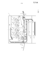
[0008] Фиг. 1 - вид в разрезе устройства формирования изображений в соответствии с вариантом осуществления 1 настоящего изобретения.[0008] FIG. 1 is a sectional view of an image forming apparatus according to
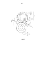
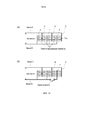
[0009] Фиг. 2 - вид в разрезе устройства нагревания изображения в соответствии с вариантом осуществления 1 настоящего изобретения.[0009] FIG. 2 is a sectional view of an image heating apparatus according to
[0010] Фиг. 3 - вид спереди устройства нагревания изображения в соответствии с вариантом осуществления 1 настоящего изобретения.[0010] FIG. 3 is a front view of an image heating apparatus according to
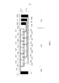
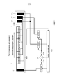
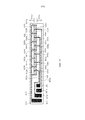
[0011] Фиг. 4 иллюстрирует конструкцию нагревателя по варианту осуществления 1.[0011] FIG. 4 illustrates a structure of a heater according to
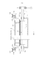
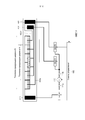
[0012] Фиг. 5 иллюстрирует конструкционную связь устройства нагревания изображения в соответствии с вариантом осуществления 1.[0012] FIG. 5 illustrates the structural relationship of the image heating apparatus according to
[0013] Фиг. 6 иллюстрирует соединитель.[0013] FIG. 6 illustrates a connector.
[0014] Фиг. 7 иллюстрирует соединитель.[0014] FIG. 7 illustrates a connector.
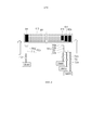
[0015] Фиг. 8 иллюстрирует размещение электрических контактов в варианте осуществления 1.[0015] FIG. 8 illustrates the placement of electrical contacts in
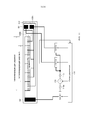
[0016] Фиг. 9 иллюстрирует конструкционную связь устройства нагревания изображения в соответствии с вариантом осуществления 2.[0016] FIG. 9 illustrates the structural relationship of the image heating apparatus according to Embodiment 2.
[0017] Фиг. 10 иллюстрирует размещение электрических контактов в варианте осуществления 2.[0017] FIG. 10 illustrates the placement of electrical contacts in Embodiment 2.
[0018] Фиг. 11 иллюстрирует конструкционную связь устройства нагревания изображения в соответствии с вариантом осуществления 3.[0018] FIG. 11 illustrates the structural relationship of the image heating apparatus according to Embodiment 3.
[0019] Фиг. 12 иллюстрирует размещение электрических контактов в варианте осуществления 3.[0019] FIG. 12 illustrates the placement of electrical contacts in Embodiment 3.
[0020] Фиг. 13 является схемой соединений традиционного нагревателя.[0020] FIG. 13 is a connection diagram of a conventional heater.
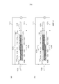
[0021] Фиг. 14 является иллюстрацией (a) типа генерации тепла, используемого с нагревателем, и иллюстрацией (b) типа переключения для теплогенерирующей области, используемой с нагревателем.[0021] FIG. 14 is an illustration (a) of a type of heat generation used with a heater, and an illustration (b) of a type of switching for a heat generating region used with a heater.
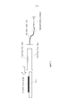
[0022] Фиг. 15 является иллюстрацией нагревателя из сравнительного примера.[0022] FIG. 15 is an illustration of a heater from a comparative example.
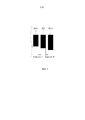
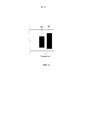
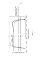
[0023] Фиг. 16 - график сравнительного испытания.[0023] FIG. 16 is a graph of a comparative test.
Описание вариантов осуществленияDescription of Embodiments
[0024] Варианты осуществления настоящего изобретения будут описаны совместно с прилагаемыми чертежами. В этом варианте осуществления устройством формирования изображений является лазерный принтер, использующий электрофотографический процесс в качестве примера. Лазерный принтер будет называться просто принтером.[0024] Embodiments of the present invention will be described in conjunction with the accompanying drawings. In this embodiment, the image forming apparatus is a laser printer using an electrophotographic process as an example. A laser printer will simply be called a printer.
[Вариант осуществления 1][Embodiment 1]
[Устройство формирования изображений][Imaging Device]
[0025] Фиг. 1 является видом в разрезе принтера 1, который является устройством формирования изображений по этому варианту осуществления. Принтер 1 содержит узел 10 формирования изображений и устройство 40 закрепления, в которых проявленное тонером изображение, сформированное на светочувствительном барабане 11, переносится на лист P и закрепляется на листе P, при этом на листе P формируется изображение. Со ссылкой на фиг. 1 будут подробно описаны конструкции устройства.[0025] FIG. 1 is a sectional view of a
[0026] Как показано на фиг. 1, принтер 1 включает в себя узлы 10 формирования изображений для формирования проявленных тонером изображений соответствующего цвета Y (желтый), M (пурпурный), C (голубой) и Bk (черный). Узлы 10 формирования изображений включают в себя соответственные светочувствительные барабаны 11 (11Y, 11M, 11C, 11Bk), соответствующие цветам Y, M, C, Bk, расположенные в названном порядке с левой стороны. Вокруг каждого барабана 11 обеспечены аналогичные элементы следующим образом: зарядное устройство 12 (12Y, 12M, 12C, 12Bk); экспонирующее устройство 13 (13Y, 13M, 13C, 13Bk); проявляющее устройство 14 (14Y, 14M, 14C, 14Bk); ракель 17 (17Y, 17M, 17C, 17Bk) первичного переноса; и устройство 15 (15Y, 15M, 15C, 15Bk) очистки. Конструкция для формирования проявленного тонером изображения цвета Bk будет описана как репрезентативная, а описания для других цветов пропущены для простоты посредством назначения аналогичных ссылочных позиций. Таким образом, элементы будут просто называться светочувствительным барабаном 11, зарядным устройством 12, экспонирующим устройством 13, проявляющим устройством 14, ракелем 17 первичного переноса и устройством 15 очистки с этими ссылочными позициями.[0026] As shown in FIG. 1, the
[0027] Светочувствительный барабан 11 в качестве электрофотографического светочувствительного элемента вращается посредством движущего источника (не показан) в направлении, обозначенном стрелкой (направление против часовой стрелки на фиг. 1). Вокруг светочувствительного барабана 11 обеспечены зарядное устройство 12, экспонирующее устройство 13, проявляющее устройство 14, ракель 17 первичного переноса и устройство 15 очистки в названном порядке.[0027] The photosensitive drum 11, as an electrophotographic photosensitive member, is rotated by a moving source (not shown) in the direction indicated by an arrow (counterclockwise direction in FIG. 1). Around the photosensitive drum 11, a charger 12, an
[0028] Поверхность светочувствительного барабана 11 электрически заряжается зарядным устройством 12. После этого поверхность светочувствительного барабана 11 подвергается воздействию лазерного луча с помощью экспонирующего устройства 13 в соответствии с информацией об изображении, так что формируется электростатическое скрытое изображение. Электростатическое скрытое изображение проявляется проявляющим устройством 14 в проявленное тонером изображение с цветом Bk. При этом аналогичные процессы выполняются для других цветов. Проявленное тонером изображение последовательно переносится со светочувствительного барабана 11 на ленту 31 промежуточного переноса ракелем 17 первичного переноса (первичный перенос). Тонер, остающийся на светочувствительном барабане 11 после первичного переноса изображения, удаляется устройством 15 очистки. Посредством этого поверхность светочувствительного барабана 11 очищается, чтобы быть подготовленной для следующего формирования изображения.[0028] The surface of the photosensitive drum 11 is electrically charged by the charger 12. After that, the surface of the photosensitive drum 11 is exposed to the laser beam by the
[0029] С другой стороны, лист P, содержащийся в подающей кассете 20, помещенной в лоток 25 для подачи нескольких листов, захватывается механизмом подачи (не показан) и подается на пару роликов выравнивания. Лист P является элементом, на котором формируется изображение. Конкретные примеры листа P представляют собой простую бумагу, плотный лист, лист из полимерного материала, пленку диапроектора и т.п. Пара роликов 23 выравнивания однажды останавливает лист P для подачи с корректным наклоном. Затем ролики 23 выравнивания подают лист P между лентой 31 промежуточного переноса и роликом 35 вторичного переноса синхронизированно с проявленным тонером изображением на ленте 31 промежуточного переноса. Ролик 35 функционирует для переноса проявленных тонером цветных изображений с ленты 31 на лист P. После этого лист P подается в устройство 40 закрепления (устройство нагревания изображения). Устройство 40 закрепления прикладывает тепло и давление к проявленному тонером изображению T на листе P, чтобы закрепить проявленное тонером изображение на листе P.[0029] On the other hand, the sheet P contained in the
[Устройство закрепления][Fastener]
[0030] Будет описано устройство 40 закрепления, которое является устройством нагревания изображения, используемым в принтере 1. Фиг. 2 является видом в разрезе устройства 40 закрепления. Фиг. 3 является видом спереди устройства 40 закрепления. Фиг. 5 иллюстрирует конструкционную связь устройства 40 закрепления.[0030] An
[0031] Устройство 40 закрепления является устройством нагревания изображения для нагревания изображения на листе блоком 60 нагревателя (блоком 60). Блок 60 включает в себя гибкую тонкую закрепляющую ленту 603 и нагреватель 600, контактирующий с внутренней поверхностью ленты 603 для нагревания этой ленты 603 (конструкция с низкой теплоемкостью). Таким образом, лента 603 может быть эффективно нагрета, так что в начале операции закрепления достигается быстрое повышение температуры. Как показано на фиг. 2, лента 603 зажата между нагревателем 600 и прижимным роликом 70 (роликом 70), посредством которых сформирован зажим N. Лента 603 вращается в обозначенном стрелкой направлении (по часовой стрелке на фиг. 2), а ролик 70 вращается в обозначенном стрелкой направлении (против часовой стрелки на фиг. 2), чтобы зажать и загрузить лист P, поданный к зажиму N. При этом тепло от нагревателя 600 подводится к листу P через ленту 603 и, таким образом, проявленное тонером изображение T на листе P нагревается и прижимается зажимом N так, что проявленное тонером изображение закрепляется на листе P посредством нагревания и давления. Лист P, прошедший через фиксирующий зажим N, отделяется от ленты 603 и выгружается. В этом варианте осуществления процесс закрепления выполняется, как описано выше. Конструкция устройства 40 закрепления будет описана подробно.[0031] The fixing
[0032] Блок 60 является блоком для нагревания и прижимания изображения на листе P. Продольное направление блока 60 параллельно по отношению к продольному направлению ролика 70. Блок 60 содержит нагреватель 600, держатель 601 нагревателя, опору 602 и ленту 603.[0032]
[0033] Нагреватель 600 является нагревающим элементом для нагревания ленты 603, контактирующим с возможностью скольжения с внутренней поверхностью ленты 603. Нагреватель 600 прижимается к внутренней поверхности ленты 603 по направлению к ролику 70 так, чтобы обеспечить желаемую ширину зажима N. Размеры нагревателя 600 в этом варианте осуществления составляют 5-20 мм в ширину (размер измерен в направлении слева направо на фиг. 2), 350-400 мм в длину (размер измерен в направлении спереди назад на фиг. 2) и 0,5-2 мм по толщине. Нагреватель 600 содержит подложку 610, удлиненную в направлении, перпендикулярном направлению подачи листа P (в направлении по ширине листа P), и теплогенерирующий резистор 620 (теплогенерирующий элемент 620).[0033] The
[0034] Нагреватель 600 закреплен на нижней поверхности держателя 601 нагревателя вдоль продольного направления держателя 601 нагревателя. В этом варианте осуществления теплогенерирующий элемент 620 обеспечен на задней стороне подложки 610, которая не находится в скользящем соприкосновении с лентой 603, но теплогенерирующий элемент 620 может быть обеспечен на передней поверхности подложки 610, которая находится в скользящем соприкосновении с лентой 603. Однако теплогенерирующий элемент 620 предпочтительно обеспечивают на задней стороне подложки 610, посредством чего достигается эффект однородного нагревания подложки 610 с точки зрения предотвращения неоднородного приложения тепла, которое может быть вызвано не теплогенерирующим участком теплогенерирующего элемента 620. Далее будут описаны подробные сведения о нагревателе 600.[0034] A
[0035] Лента 603 является цилиндрической (бесконечной) лентой (пленкой) для нагревания изображения на листе в зажиме N. Например, лента 603 содержит материал-основу 603a, расположенный на нем упругий слой 603b и разделительный слой 603c на упругом слое 603b. Материал-основы 603a может быть сделан из металлического материала, такого как нержавеющая сталь или никель, или теплостойкой смолы, такой как полиимид. Упругий слой 603b может быть сделан из упругого и теплостойкого материала, такого как кремнийорганический каучук или фторсодержащий каучук. Разделительный слой 603c может быть сделан из фторированной смолы или кремнийорганической смолы.[0035] The
[0036] Лента 603 по этому варианту осуществления имеет размеры приблизительно 30 мм по внешнему диаметру, приблизительно 330 мм в длину (размер измерен в направлении спереди назад на фиг. 2), приблизительно 30 мкм в толщину, а материалом материала-основы 603a является никель. Упругий слой 603b из кремнийорганического каучука, имеющий толщину приблизительно 400 мкм, сформирован на материале-основе 603a, и трубка из фторсодержащей смолы (разделительный слой 603c), имеющая толщину приблизительно 20 мкм, покрывает упругий слой 603b.[0036] The
[0037] Контактная поверхность ленты подложки 610 может быть снабжена слоем полиимида, имеющим толщину приблизительно 10 мкм, в качестве скользящего слоя 603d. Когда обеспечен слой полиимида, сопротивление трения между закрепляющей лентой 603 и нагревателем 600 является низким и, таким образом, может быть подавлен износ внутренней поверхности ленты 603. Чтобы дополнительно увеличить способность к скольжению, на внутреннюю поверхность ленты может быть нанесена смазка, такая как консистентная смазка.[0037] The contact surface of the tape of the
[0038] Держатель 601 нагревателя (держатель 601) поддерживает нагреватель 600 в состоянии направления нагревателя 600 к внутренней поверхности ленты 603. Держатель 601 имеет полудугообразное поперечное сечение (поверхность на фиг. 2) и регулирует орбиту вращения ленты 603. Держатель 601 может быть сделан из теплостойкой смолы или т.п. В этом варианте осуществления это Zenite 7755 (товарная марка), доступный от Dupont.[0038] The
[0039] Опора 602 поддерживает нагреватель 600 посредством держателя 601. Опору 602 предпочтительно делают из материала, который нелегко деформируется, даже когда к нему подано высокое давление, и в этом варианте осуществления, она сделана из SUS304 (нержавеющей стали).[0039] The
[0040] Как показано на фиг. 3, опора 602 поддерживается левым и правым фланцами 411a и 411b на противоположных оконечных участках относительно продольного направления. Фланцы 411a и 411b могут называться просто фланцем 411. Фланец 411 регулирует движение ленты 603 в продольном направлении и конфигурацию направления по окружности ленты 603. Фланец 411 сделан из теплостойкой смолы и т.п. В этом варианте осуществления это PPS (полифениленсульфидная смола).[0040] As shown in FIG. 3, the
[0041] Между фланцем 411a и прижимной ручкой 414a сжата прижимающая пружина 415a. Кроме того, между фланцем 411b и прижимной ручкой 414b сжата прижимающая пружина 415b. Прижимающие пружины 415a и 415b могут называться просто прижимающей пружиной 415. При такой конструкции упругая сила прижимающей пружины 415 прикладывается к нагревателю 600 через фланец 411 и опору 602. Лента 603 прижимается к верхней поверхности ролика 70 с заданной прижимающей силой с формированием зажима N, имеющего заданную ширину зажима. В этом варианте осуществления давление составляет приблизительно 156,8 Н на одной стороне оконечного участка и в целом приблизительно 313,6 Н (32 кгс).[0041] A
[0042] Как показано на фиг. 3, соединитель 700 обеспечен в качестве элемента подачи электроэнергии, электрически соединенного с нагревателем 600, для подачи электроэнергии на нагреватель 600. Соединители 700a, 700b могут называться просто соединителем 700. Соединитель 700 обеспечен с возможностью отсоединения на одном оконечном по длине участке нагревателя 600. Соединитель 700 обеспечен с возможностью отсоединения на другом оконечном по длине участке нагревателя 600. Соединитель 700 легко монтируется с возможностью отсоединения на нагревателе 600 и, таким образом, сборка устройства 40 закрепления и замена нагревателя 600 или ленты 603 при повреждении нагревателя 600 является простой, тем самым обеспечивая хорошую возможность для технического обслуживания. Подробные сведения о соединителе 700 будут описаны далее.[0042] As shown in FIG. 3, a connector 700 is provided as an electric power supply element electrically connected to a
[0043] Как показано на фиг. 2, ролик 70 является элементом формирования зажима, который контактирует с наружной поверхностью ленты 603 для взаимодействия с лентой 603, с формированием зажима N. Ролик 70 имеет многослойную конструкцию на металлическом сердечнике, при этом многослойная конструкция включает в себя упругий слой 72 на металлическом сердечнике 71 и разделительный слой 73 на упругом слое 72. Примеры материалов металлического сердечника 71 включают в себя SUS (нержавеющую сталь), SUM (содержащую серу легкообрабатываемую сталь), Al (алюминий) и т.п. Примеры материалов упругого слоя 72 включают в себя слой из упругого твердого каучука, слой из упругой вспененной резины, слой из упругой пористой резины и т.п. Примеры материалов разделительного слоя 73 включают в себя фторсодержащую смолу.[0043] As shown in FIG. 2, the
[0044] Ролик 70 по этому варианту осуществления включает в себя металлический сердечник из стали, упругий слой 72 из вспененного кремнийорганического каучука на металлическом сердечнике 71 и разделительный слой 73 из трубки из фторсодержащей смолы на упругом слое 72. Размеры участка ролика 70, имеющего упругий слой 72 и разделительный слой 73, составляют приблизительно 25 мм по внешнему диаметру и приблизительно 330 мм в длину.[0044] The
[0045] Термистор 630 является температурным датчиком, обеспеченным на задней стороне нагревателя 600 (на противоположной стороне относительно стороны скользящей поверхности). Термистор 630 связан с нагревателем 600 в таком состоянии, что он изолирован от теплогенерирующего элемента 620. Термистор 630 имеет функцию регистрации температуры нагревателя 600. Как показано на фиг. 5, термистор 630 соединен со схемой 100 управления с помощью аналого-цифрового (A/D) преобразователя и подает в схему 100 управления выходной сигнал, соответствующий зарегистрированной температуре.[0045] The
[0046] Схема 100 управления содержит схему, включающую в себя центральный процессор (ЦП; CPU), работающий для различных управлений, энергонезависимый носитель, такой как постоянное запоминающее устройство (ПЗУ: ROM), хранящий различные программы. Программы хранятся в ПЗУ, а ЦП считывает и исполняет их, чтобы выполнить различные управления. Схема 100 управления может быть интегральной схемой, такой как специализированная интегральная схема (ASIC), если она способна выполнять подобное действие.[0046] The
[0047] Как показано на фиг. 5, схема 100 управления электрически соединена с источником 110 напряжения так, чтобы управлять подачей электропитания от источника 110 напряжения. Схема 100 управления электрически соединена с термистором 630, чтобы принимать выходной сигнал термистора 630.[0047] As shown in FIG. 5, the
[0048] Схема 100 управления использует информацию о температуре, полученную от термистора 630, для управления подачей электропитания для источника 110 напряжения. В частности, схема 100 управления управляет электроэнергией для нагревателя 600 через источник 110 напряжения на основе выходного сигнала термистора 630. В этом варианте осуществления схема 100 управления выполняет управление волновым числом выходного сигнала источника 110 напряжения для регулирования количества генерируемого нагревателем 600 тепла. Посредством такого управления нагреватель 600 поддерживается при заданной температуре (например, приблизительно 180 градусов по Цельсию).[0048] The
[0049] Как показано на фиг. 3, металлический сердечник 71 ролика 70 удерживается с возможностью вращения подшипниками 41a и 41b, обеспеченными на задней стороне и передней стороне боковой пластины 41, соответственно. Один осевой конец металлического сердечника снабжен шестерней G для передачи движущей силы от двигателя M металлическому сердечнику 71 ролика 70. Как показано на фиг. 2, ролик 70, принимающий движущую силу от двигателя M, вращается в направлении, обозначенном стрелкой (в направлении по часовой стрелке). В зажиме N движущая сила передается ленте 603 посредством ролика 70, так что лента 603 вращается в направлении, обозначенном стрелкой (в направлении против часовой стрелки).[0049] As shown in FIG. 3, the
[0050] Двигатель M является приводной частью для приведения в движение ролика 70 через шестерню G. Как показано на фиг. 5, схема 100 управления электрически соединена с двигателем M, чтобы управлять подачей электропитания на двигатель M. Когда электроэнергия подается под управлением схемы 100 управления, двигатель M начинает вращать шестерню G.[0050] The motor M is the drive part for driving the
[0051] Схема 100 управления управляет вращением двигателя M. Схема 100 управления вращает ролик 70 и ленту 603 с использованием двигателя M на заданной скорости. Она управляет двигателем таким образом, что скорость листа P, зажатого и загружаемого зажимом N при операции закрепления, совпадает с заданной скоростью процесса (например, приблизительно 200 мм/с).[0051] The
[Нагреватель][Heater]
[0052] Будет подробно описана конструкция нагревателя 600, используемого в устройстве 40 закрепления. Фиг. 4 иллюстрирует конструкцию нагревателя по варианту осуществления 1. Фиг. 6 иллюстрирует соединитель. Часть (a) фиг. 14 иллюстрирует тип генерации тепла, используемый в нагревателе 600. Часть (b) фиг. 14 иллюстрирует тип переключения теплогенерирующей области, используемый нагревателем 600.[0052] The structure of the
[0053] Нагреватель 600 по этому варианту осуществления является нагревателем, использующим тип генерации тепла, показанный на частях (a) и (b) фиг. 14. Как показано на части (a) фиг. 14, электроды с первого по третий электрически соединены с электропроводной линией A, а электроды с четвертого по шестой электрически соединены с электропроводной линией B. Электроды, соединенные с электропроводными линиями A, и электроды, соединенные с электропроводными линиями B, чередуются (размещаются поочередно) вдоль продольного направления (направления слева направо на части (a) фиг. 14), а теплогенерирующие элементы электрически присоединены между смежными электродами. Когда между электропроводной линией A и электропроводной линией B подают напряжение V, между смежными электродами вырабатывается разность потенциалов. В результате электрические токи текут через теплогенерирующие элементы, а направления электрических токов через смежные теплогенерирующие элементы являются противоположными друг другу. Как показано на части (b) фиг. 14, между электропроводной линией B и шестым электродом обеспечен переключатель и т.п., и когда переключатель разомкнут, второй электрод и шестой электрод C находятся под одинаковым потенциалом и, таким образом, электрический ток не течет через теплогенерирующий элемент между ними. В этой системе теплогенерирующие элементы, расположенные в продольном направлении, независимо снабжаются энергией, так что только часть теплогенерирующих элементов может быть снабжена энергией при выключении части из них. Другими словами, в системе теплогенерирующая область может быть изменена посредством обеспечения переключателя и т.п. в электропроводной линии. В нагревателе 600 теплогенерирующая область теплогенерирующего элемента 620 может быть изменена с использованием вышеописанной системы.[0053] The
[0054] При снабжении энергией теплогенерирующий элемент генерирует тепло независимо от направления электрического тока, но предпочтительно, чтобы теплогенерирующие элементы и электроды располагались таким образом, чтобы токи текли вдоль продольного направления. Такое размещение имеет преимущество перед размещением, в котором направления электрических токов являются направлением по ширине, перпендикулярном продольному направлению (направлением сверху вниз на части (a) фиг. 14) со следующей точки зрения. Когда генерация джоулева тепла производится посредством снабжения электрической энергией теплогенерирующего элемента, этот теплогенерирующий элемент генерирует тепло соответственно значению своего сопротивления, и, таким образом, размеры и материал теплогенерирующего элемента выбирают в соответствии с направлением электрического тока так, чтобы значение сопротивления находилось на желаемом уровне. Размер подложки, на которой обеспечен теплогенерирующий элемент, очень мал в направлении ширины по сравнению с размером в продольном направлении. Таким образом, если электрический ток течет в направлении ширины, трудно обеспечить теплогенерирующему элементу желаемое значение сопротивления, используя материал с низким сопротивлением. С другой стороны, когда электрический ток течет в продольном направлении, относительно легко обеспечить теплогенерирующему элементу желаемое значение сопротивления, используя материал с низким сопротивлением. Кроме того, когда для теплогенерирующего элемента используется материал с высоким сопротивлением, может возникнуть неоднородность температуры вследствие неоднородности толщины теплогенерирующего элемента, когда он снабжается энергией. Например, когда материал теплогенерирующего элемента нанесен на подложку вдоль продольного направления посредством трафаретной печати и т.п., может возникнуть неоднородность толщины примерно 5% в направлении по ширине. Это вызвано тем, что неоднородность нанесения материала теплогенерирующего элемента возникает из-за небольшого перепада давлений в направлении ширины наносящего ракеля. Поэтому предпочтительно, чтобы теплогенерирующие элементы и электроды располагались так, чтобы электрические токи текли в продольном направлении.[0054] When supplied with energy, the heat generating element generates heat regardless of the direction of the electric current, but it is preferable that the heat generating elements and electrodes are arranged so that currents flow along the longitudinal direction. Such an arrangement takes precedence over an arrangement in which the directions of electric currents are a width direction perpendicular to the longitudinal direction (top to bottom direction on part (a) of FIG. 14) from the following point of view. When the Joule heat is generated by supplying electric energy to a heat generating element, this heat generating element generates heat according to its resistance value, and thus, the dimensions and material of the heat generating element are selected in accordance with the direction of the electric current so that the resistance value is at the desired level. The size of the substrate on which the heat generating element is provided is very small in the width direction compared with the size in the longitudinal direction. Thus, if the electric current flows in the width direction, it is difficult to provide the heat generating element with the desired resistance value using a material with low resistance. On the other hand, when electric current flows in the longitudinal direction, it is relatively easy to provide the heat generating element with the desired resistance value using a material with low resistance. In addition, when a material with a high resistance is used for the heat generating element, temperature inhomogeneity may occur due to the heterogeneity of the thickness of the heat generating element when it is supplied with energy. For example, when the material of the heat generating element is deposited on the substrate along the longitudinal direction by screen printing or the like, a thickness inhomogeneity of about 5% in the width direction can occur. This is due to the fact that the heterogeneity of the application of the material of the heat-generating element occurs due to a small pressure drop in the direction of the width of the applying doctor blade. Therefore, it is preferable that the heat generating elements and electrodes are arranged so that electric currents flow in the longitudinal direction.
[0055] В этом случае, когда электроэнергия подается индивидуально к теплогенерирующим элементам, размещенным в продольном направлении, предпочтительно, чтобы электроды и теплогенерирующие элементы располагались так, чтобы направления электрических токов чередовались между смежными элементами. Что касается размещений теплогенерирующих элементов и электродов, предполагается разместить каждый теплогенерирующий элемент с присоединением к электродам на своих противоположных концах в продольном направлении, и при этом электроэнергия подается в продольном направлении. Однако при таком размещении между смежными теплогенерирующими элементами обеспечиваются два электрода, и в результате имеется вероятность короткого замыкания. Кроме того, число необходимых электродов велико, и в результате между смежными теплогенерирующими элементами имеется большой не теплогенерирующий участок. Таким образом, предпочтительно разместить теплогенерирующие элементы и электроды таким образом, чтобы электрод был общим для смежных теплогенерирующих элементов. При таком размещении можно избежать вероятности короткого замыкания между упомянутыми электродами, и не теплогенерирующий участок может быть сделан маленьким.[0055] In this case, when electric power is supplied individually to the heat generating elements arranged in the longitudinal direction, it is preferable that the electrodes and the heat generating elements are arranged so that the directions of the electric currents alternate between adjacent elements. With regard to the placement of heat-generating elements and electrodes, it is proposed to place each heat-generating element with connection to the electrodes at their opposite ends in the longitudinal direction, and while the electricity is supplied in the longitudinal direction. However, with this arrangement, two electrodes are provided between adjacent heat generating elements, and as a result there is a possibility of a short circuit. In addition, the number of electrodes needed is large, and as a result, between adjacent heat-generating elements there is a large non-heat-generating area. Thus, it is preferable to place the heat generating elements and electrodes in such a way that the electrode is common to adjacent heat generating elements. With this arrangement, the likelihood of a short circuit between said electrodes can be avoided, and a non-heat generating portion can be made small.
[0056] В этом варианте осуществления общая электропроводная линия 640 соответствует электропроводной линии A по части (a) фиг. 14, а противоположные электропроводные линии 650, 660a, 660b соответствуют электропроводной линии B. Кроме того, общие электроды 652a-652g соответствуют электродам с первого по третий части (a) по фиг. 14, а противоположные электроды 652a-652d, 662a, 662b соответствуют электродам с четвертого по шестой. Теплогенерирующие элементы 620a-620l соответствуют теплогенерирующим элементам по части (a) фиг. 14. В дальнейшем общие электроды 642a-642g являются просто общим электродом 642. Противоположные электроды 652a-652e называются просто противоположным электродом 652. Противоположные электропроводные линии 660a, 660b называются просто противоположной электропроводной линией 660. Теплогенерирующие элементы 620a-620l называются просто теплогенерирующим элементом 620. Конструкция нагревателя 600 будет подробно описана со ссылкой на прилагаемые чертежи.[0056] In this embodiment, the common
[0057] Как показано на фиг. 4 и 6, нагреватель 600 содержит подложку 610, теплогенерирующий элемент 620 на подложке 610, электропроводный рисунок (электропроводную линию) и слой 680 изоляционного покрытия, покрывающий теплогенерирующий элемент 620 и электропроводный рисунок.[0057] As shown in FIG. 4 and 6, the
[0058] Подложка 610 определяет размеры и конфигурацию нагревателя 600 и является контактирующей с лентой 603 вдоль продольного направления подложки 610. Материал подложки 610 является керамическим материалом, таким как оксид алюминия, нитрид алюминия или т.п., который имеет высокую теплостойкость, теплопроводность, хорошие электроизоляционные свойства или т.п. В этом варианте осуществления подложка является плоским элементом из оксида алюминия, имеющим длину (измеренную в направлении слева направо на фиг. 4) приблизительно 400 мм, ширину (в направлении сверху вниз на фиг. 4) приблизительно 8 мм и толщину приблизительно 1 мм.[0058] The
[0059] На задней стороне подложки 610 теплогенерирующий элемент 620 и электропроводный рисунок (электропроводная линия) обеспечены посредством способа печати толстых пленок (способа трафаретной печати) с использованием электропроводной пасты для нанесения толстых плёнок. В этом варианте осуществления для электропроводного рисунка используется серебряная паста, так что удельное сопротивление является низким, а для теплогенерирующего элемента 620 используется паста сплава серебра и палладия, так что удельное сопротивление является высоким. Как показано на фиг. 6, теплогенерирующий элемент 620 и электропроводный рисунок покрыты слоем 680 изоляционного покрытия из теплостойкого стекла, так что они электрически защищены от утечки и короткого замыкания.[0059] On the back side of the
[0060] Как показано на фиг. 4, на одной стороне оконечного участка подложки 610 относительно продольного направления обеспечены электрические контакты 641 как часть электропроводного рисунка. На другой стороне 610b оконечного участка подложки 610 относительно продольного направления обеспечены электрические контакты 651, 661a, 661b как часть электропроводного рисунка. В центральной области 610c подложки 610 относительно продольного направления обеспечены теплогенерирующий элемент 620 и общий электрод 642, и противоположные электроды 652, 662 как часть электропроводного рисунка. На одной стороне 610d оконечного участка подложки 610 вне теплогенерирующего элемента 620 относительно направления по ширине обеспечена общая электропроводная линия 640 как часть электропроводного рисунка. На другой стороне 610e оконечного участка подложки 610 вне теплогенерирующего элемента 620 относительно направления по ширине обеспечены противоположные электропроводные линии 650 и 660 как часть электропроводного рисунка.[0060] As shown in FIG. 4,
[0061] Теплогенерирующие элементы 620 (620a-620l) являются резисторами для генерации джоулева тепла при подаче на них электропитания. Теплогенерирующий элемент 620 является одним теплогенерирующим элементом, простирающимся в продольном направлении на подложке 610, и расположен в области 610c (фиг. 4), смежной с центральным участком подложки 610. Теплогенерирующий элемент 620 имеет желаемую величину сопротивления и имеет ширину (измеренную в направлении по ширине подложки 610) 1-4 мм, толщину 5-20 мкм. Теплогенерирующий элемент 620 в этом варианте осуществления имеет ширину приблизительно 2 мм и толщину приблизительно 10 мкм. Общая длина теплогенерирующего элемента 620 в продольном направлении составляет приблизительно 320 мм, которая достаточна для покрытия ширины листа P размера A4 (приблизительно 297 мм по ширине).[0061] The heat generating elements 620 (620a-620l) are resistors for generating Joule heat when power is supplied to them. The heat-generating
[0062] На теплогенерирующий элемент 620 с интервалами в продольном направлении наслоены семь общих электродов 642a-642g, которые будут описаны далее. Другими словами, теплогенерирующий элемент 620 разделен на шесть секций общими электродами 642a-642g вдоль продольного направления. Длины каждой из секций, измеренные в продольном направлении подложки 610, составляют приблизительно 53,3 мм. На центральных участках соответствующих секций теплогенерирующего элемента 620 наслоен один из шести противоположных электродов 652, 662 (652a-652d, 662a, 662b). Таким образом, теплогенерирующий элемент 620 разделен на 12 подсекций. Теплогенерирующий элемент 620, разделенный на 12 подсекций, может рассматриваться как множество теплогенерирующих элементов 620a-620l. Другими словами, теплогенерирующие элементы 620a-620l электрически соединяют друг с другом смежные электроды. Длины подсекций, измеренные в продольном направлении подложки 610, составляют приблизительно 26,7 мм. Величины сопротивления подсекций теплогенерирующего элемента 620 относительно продольного направления составляют приблизительно 120 Ом. При такой конструкции теплогенерирующий элемент 620 способен генерировать тепло в частичной области или областях относительно продольного направления.[0062] Seven
[0063] Удельные сопротивления теплогенерирующих элементов 620 относительно продольного направления являются однородными, а теплогенерирующие элементы 620a-620l имеют практически одинаковые размеры. Таким образом, величины сопротивления теплогенерирующих элементов 620a-620l практически равны. Когда они снабжаются электроэнергией параллельно, распределение генерации тепла теплогенерирующего элемента 620 является однородным. Однако не является неизбежным, что теплогенерирующие элементы 620a-620l имеют практически одинаковые размеры и/или практически одинаковые удельные сопротивления. Например, величины сопротивления теплогенерирующих элементов 620a и 620l могут быть отрегулированы таким образом, чтобы предотвратить снижение температуры в оконечных по длине участках теплогенерирующего элемента 620. В тех положениях теплогенерирующего элемента 620, где обеспечены общий электрод 642 и противоположный электрод 652, 662, генерация тепла теплогенерирующего элемента 620 практически нулевая. Однако функция однородности тепла подложки 610 делает влияние на процесс закрепления незначительным, если ширина электрода составляет, например, не больше 1 мм. В этом варианте осуществления ширина каждого электрода составляет не больше 1 мм. Общие электроды 642 (642a-642g) являются частью вышеописанного электропроводного рисунка. Общий электрод 642 простирается в направлении по ширине подложки 610 перпендикулярно продольному направлению теплогенерирующего элемента 620. В этом варианте осуществления общий электрод 642 наслоен на теплогенерирующий элемент 620. Общие электроды 642 являются нечетными электродами из электродов, соединенных с теплогенерирующим элементом 620, если считать от одного конца по длине теплогенерирующего элемента 620. Общий электрод 642 соединен с одним контактом 110a источника 110 напряжения через общую электропроводную линию 640, как будет описано далее.[0063] The resistivities of the
[0064] Противоположные электроды 652, 662 являются частью вышеописанного электропроводного рисунка. Противоположные электроды 652, 662 простираются в направлении по ширине подложки 610 перпендикулярно продольному направлению теплогенерирующего элемента 620. Противоположные электроды 652, 662 наслоены на теплогенерирующий элемент 620. Противоположные электроды 652, 662 являются прочими электродами из электродов, соединенных с теплогенерирующим элементом 620, помимо вышеописанного общего электрода 642. Таким образом, в этом варианте осуществления они являются четными электродами, если считать от одного конца по длине теплогенерирующего элемента 620.[0064] Opposite electrodes 652, 662 are part of the above-described conductive pattern. Opposite electrodes 652, 662 extend in the direction along the width of the
[0065] Таким образом, общий электрод 642 и противоположные электроды 662, 652 размещаются поочередно вдоль продольного направления теплогенерирующего элемента. Противоположные электроды 652, 662 соединены с другим контактом 110b источника 110 напряжения через противоположные электропроводные линии 650, 660, как будет описано далее.[0065] Thus, the common electrode 642 and the opposite electrodes 662, 652 are placed alternately along the longitudinal direction of the heat generating element. Opposite electrodes 652, 662 are connected to another terminal 110b of the
[0066] Общий электрод 642 и противоположный электрод 652, 662 функционируют как множество электродных участков для подачи электроэнергии на теплогенерирующий элемент 620.[0066] The common electrode 642 and the opposite electrode 652, 662 function as a plurality of electrode sections for supplying electricity to the
[0067] В этом варианте осуществления нечетные электроды являются общими электродами 642, а четные электроды являются противоположными электродами 652, 662, но конструкция нагревателя 600 не ограничена этим примером. Например, четные электроды могут быть общими электродами 642, и нечетные электроды могут быть противоположными электродами 652, 662.[0067] In this embodiment, the odd electrodes are common electrodes 642, and the even electrodes are opposite electrodes 652, 662, but the design of the
[0068] Кроме того, в этом варианте осуществления четыре из всех противоположных электродов, соединенных с теплогенерирующим элементом 620, являются противоположным электродом 652. В этом варианте осуществления два из всех противоположных электродов, соединенных с теплогенерирующим элементом 620, являются противоположным электродом 662. Однако распределение противоположных электродов не ограничено этим примером и может быть изменено в зависимости от теплогенерирующей ширины нагревателя 600. Например, два электрода могут быть противоположным электродом 652, а четыре электрода могут быть противоположным электродом 662.[0068] Furthermore, in this embodiment, four of all opposite electrodes connected to the
[0069] Общая электропроводная линия 640 является частью вышеописанного электропроводного рисунка. Общая электропроводная линия 640 простирается вдоль продольного направления подложки 610 по направлению к одной стороне 610a оконечного участка подложки на одной стороне 610d оконечного участка подложки. Общая электропроводная линия 640 соединена с общими электродами 642 (642a-642g), которые в свою очередь соединены с теплогенерирующим элементом 620 (620a-620l). Общая электропроводная линия 640 соединена с электрическим контактом 641, который будет описан далее. В этом варианте осуществления, чтобы гарантировать изоляцию из слоя 680 изоляционного покрытия, между общей электропроводной линией 640 и каждым противоположным электродом обеспечен промежуток приблизительно 400 мкм.[0069] The common
[0070] Противоположная электропроводная линия 650 является частью вышеописанного электропроводного рисунка. Противоположная электропроводная линия 650 простирается вдоль продольного направления подложки 610 по направлению к другому оконечному участку 610a подложки на другой стороне 610e оконечного участка подложки. Противоположная электропроводная линия 650 соединена с противоположными электродами 652 (652a-652d), которые, в свою очередь, соединены с теплогенерирующими элементами 620 (620c-620j), противоположная электропроводная линия 650 соединена с электрическим контактом 651, который будет описан далее.[0070] The opposite
[0071] Противоположная электропроводная линия 660 (660a, 660b) является частью вышеописанного электропроводного рисунка. Противоположная электропроводная линия 660a простирается вдоль продольного направления подложки 610 по направлению к другому оконечному участку 610a подложки на другой стороне 610e оконечного участка подложки. Противоположная электропроводная линия 660a соединена с противоположным электродом 662a, который, в свою очередь, соединен с теплогенерирующим элементом 620 (620a, 620b). Противоположная электропроводная линия 660a соединена с электрическим контактом 661a, который будет описан далее. Противоположная электропроводная линия 660b простирается вдоль продольного направления подложки 610 по направлению к другому оконечному участку 610b подложки на другой стороне 610e оконечного участка подложки. Противоположная электропроводная линия 660b соединена с противоположным электродом 662b, который, в свою очередь, соединен с теплогенерирующим элементом 620 (620k, 620l). Противоположная электропроводная линия 660b соединена с электрическим контактом 661b, который будет описан далее. В этом варианте осуществления, чтобы гарантировать изоляцию из слоя 680 изоляционного покрытия, между противоположной электропроводной линией 660b и общим электродом 642 обеспечен промежуток приблизительно 400 мкм. Кроме того, между противоположными электропроводными линиями 660a и 650 и между противоположными электропроводными линиями 600b и 650 обеспечены промежутки приблизительно 100 мкм.[0071] The opposite conductive line 660 (660a, 660b) is part of the above-described conductive pattern. The opposite
[0072] Электрические контакты 641, 651, 661a, 661b являются частью вышеописанного электропроводного рисунка. На одной стороне 610a оконечного участка подложки обеспечен электрический контакт. На другой стороне 610b оконечного участка подложки обеспечены электрические контакты 651, 661a, 661b. Как показано на фиг. 6, участок, включающий в себя электрические контакты 641, 651, 661a, 661b, не покрыт слоем 680 изоляционного покрытия, так что электрические контакты 641, 651, 661a, 661b открыты. Таким образом, электрический контакт 641 может контактировать и электрически соединяться с соединителем 700a. Электрические контакты 651, 661a, 661b могут контактировать и электрически соединяться с соединителем 700b.[0072]
[0073] Когда напряжение подают между электрическим контактом 641 и электрическим контактом 651 через соединение между нагревателем 600 и соединителем 700, между общим электродом 642 (642b-642f) и противоположным электродом 652 (652a-652d) вырабатывается разность потенциалов. Таким образом, через теплогенерирующие элементы 620c, 620d, 620e, 620f, 620g, 620h, 620i, 620j токи текут вдоль продольного направления подложки 610, и направления токов через смежные теплогенерирующие элементы являются практически противоположными друг другу. Теплогенерирующие элементы 620c, 620d, 620e, 620f, 620g, 620h, 620i соответственно генерируют тепло как первая теплогенерирующая область.[0073] When a voltage is applied between the
[0074] Когда напряжение подают между электрическим контактом 641 и электрическим контактом 661a через соединение между нагревателем 600 и соединителем 700, между общим электродом 642a-642b и противоположным электродом 662a вырабатывается разность потенциалов. Таким образом, через теплогенерирующие элементы 620a, 620b токи текут вдоль продольного направления подложки 610, и направления токов через смежные теплогенерирующие элементы являются практически противоположными друг другу. Теплогенерирующие элементы 620a, 620b генерируют тепло как вторая теплогенерирующая область.[0074] When a voltage is applied between the
[0075] Когда напряжение подают между электрическим контактом 641 и электрическим контактом 661b через соединение между нагревателем 600 и соединителем 700, между общими электродами 642f и 642g и противоположным электродом 662b через общую электропроводную линию 640 и противоположную электропроводную линию 660b вырабатывается разность потенциалов. Таким образом, через теплогенерирующие элементы 620k, 620l токи текут вдоль продольного направления подложки 610, и направления токов через смежные теплогенерирующие элементы являются практически противоположными друг другу. Теплогенерирующие элементы 620k, 620l генерируют тепло как третья теплогенерирующая область.[0075] When a voltage is applied between the
[0076] Таким образом, при выборе электрических контактов, снабжаемых напряжением, может снабжаться энергией желаемый один или несколько из теплогенерирующих элементов 620a - 620l.[0076] Thus, when selecting electrical contacts energized, the desired one or more of the
[Соединитель][Connector]
[0077] Будет подробно описан соединитель 700, используемый с устройством 40 закрепления. Фиг. 7 иллюстрирует контактную клемму. Соединители 700a и 700b по этому варианту осуществления электрически соединены с нагревателем 600 посредством монтажа на нагревателе 600. Как показано на фиг. 6, соединитель 700a содержит контактную клемму 710, электрически соединяемую с электрическим контактом 641. Контактная клемма 710 покрыта корпусом 750. Соединитель 700b включает в себя контактную клемму 720a, электрически соединяемую с электрическим контактом 661a, контактную клемму 720b, электрически соединяемую с электрическим контактом 661b, и контактную клемму 730, электрически соединяемую с электрическим контактом 651. Все контактные клеммы 720a, 720b, 730 находятся в корпусе 750b. Соединители 700a, 700b смонтированы на нагревателе 600 так, чтобы зажимать нагреватель 600 на его передней и задней поверхности, посредством чего контактные клеммы соединяются с электрическими контактами, соответственно. В устройстве 40 закрепления по этому варианту осуществления, имеющему вышеописанные конструкции, для электрического соединения между соединителями и электрическими контактами не используется никакая пайка и т.п. Таким образом, электрическое соединение между нагревателем 600 и соединителем 700, которые нагреваются во время операции закрепления, может выполняться и сохраняться с высокой надежностью. В устройстве 40 закрепления по этому варианту осуществления соединитель 700 является монтируемым с возможностью отсоединения относительно нагревателя 600 и, таким образом, лента 603 и/или нагреватель 600 могут быть без труда заменены. Конструкция соединителя 700 будет описана подробно.[0077] A connector 700 used with an
[0078] Как показано на фиг. 6, соединитель 700, снабженный металлическими контактными клеммами 710, монтируется на нагревателе 600 в направлении по ширине подложки 610 на одной стороне 610a оконечного участка подложки от оконечного участка подложки 610 относительно направления по ширине. Соединитель 700b, снабженный контактными клеммами 720b, 730, смонтирован на нагревателе 600 от оконечного по длине участка на другой стороне 610b оконечного участка подложки.[0078] As shown in FIG. 6, a connector 700 provided with
[0079] Замена ленты 603 и/или нагревателя 600 желательно выполнять с монтажом и демонтажом соединителя 700a. Это вызвано тем, что соединитель 700a имеет только одну контактную клемму и, таким образом, даже если положение монтажа относительно нагревателя 600 немного отклонено, контактная клемма вряд ли соединится с электрическим контактом, отличным от электрического контакта 641 (отсутствует подверженность короткому замыканию). Другими словами, при конструкции по этому варианту осуществления монтаж и демонтаж соединителя 700a относительно нагревателя 600 может быть выполнен с дополнительной безопасностью. Конструкция соединителя 700 будет описана подробно.[0079] It is desirable to replace the
[0080] Контактные клеммы 710, 720a, 720b, 730 будут описаны с помощью контактной клеммы 710 в качестве примера. Контактная клемма 710 функционирует для электрического соединения электрического контакта 641 с переключателем SW643, который будет описан далее. Как показано на фиг. 7, контактная клемма 710 снабжена кабелем 712 для электрического соединения между переключателем SW643 и электрическим контактом 711 для обеспечения соприкосновения с электрическим контактом 641. Контактная клемма 710 имеет канало-подобную конфигурацию и при перемещении в направлении, обозначенном стрелкой на фиг. 6, она может принять нагреватель 600. Участок контактной клеммы 710, который контактирует с электрическим контактом, снабжен электрическим контактом 711, который контактирует с электрическим контактом 641, посредством чего между электрическим контактом 641 и контактной клеммой 710 устанавливается электрическое соединение. Электрический контакт 711 имеет свойство пластинчатой пружины и, таким образом, контактирует с электрическим контактом 641, одновременно прижимаясь к нему. Таким образом, контакт 710 обхватывает нагреватель 600 между передней и задней сторонами, чтобы закрепить положение нагревателя 600.[0080]
[0081] Аналогичным образом, контактная клемма 720a функционирует, чтобы обеспечивать контакт электрического контакта 661a с переключателем SW663, который будет описан далее. Контактная клемма 720a снабжена кабелем 722a для электрического соединения между переключателем SW643 и электрическим контактом 721a для обеспечения контакта с электрическим контактом 661a.[0081] Similarly, the
[0082] Аналогичным образом, контактная клемма 720b функционирует, чтобы обеспечивать контакт электрического контакта 661b с переключателем SW663, который будет описан далее. Контактная клемма 720b снабжена кабелем 722b для электрического соединения между переключателем SW663 и электрическим контактом 721b для обеспечения контакта с электрическим контактом 661b.[0082] Similarly, the
[0083] Аналогичным образом, контактная клемма 730 функционирует, чтобы обеспечивать контакт электрического контакта 651 с переключателем SW653, который будет описан далее. Контактная клемма 730 снабжена кабелем 732 для электрического соединения между переключателем SW653 и электрическим контактом 731 для обеспечения контакта с электрическим контактом 651.[0083] Similarly, the
[0084] Контактная клемма 710 из металла целиком поддерживается корпусом 750a из материала смолы. Контактная клемма 710 расположена в корпусе 750a таким образом, чтобы быть соединяемой с электрическим контактом 641, когда соединитель 700a монтируют на нагревателе 600.[0084] The
[0085] Контактные клеммы 720a, 720b, 730 из металла целиком поддерживаются корпусом 750b из материала смолы. Контактные клеммы 720b, 720b, 730 обеспечены в корпусе 750b с зазорами между смежными клеммами, чтобы они могли быть соединяемыми с электрическими контактами 661a, 661b, 651, соответственно, когда соединитель 700 монтируют на нагревателе 600. Между смежными контактными клеммами обеспечены перегородки для электрической изоляции между смежными контактными клеммами.[0085] The
[0086] В этом варианте осуществления соединитель 700 монтируют в направлении по ширине подложки 610, но этот способ монтажа не ограничивает настоящее изобретение. Например, конструкция может быть такова, что соединитель 700 монтируют в продольном направлении подложки.[0086] In this embodiment, the connector 700 is mounted in the width direction of the
[Подача электроэнергии на нагреватель][Electricity supply to the heater]
[0087] Будет описан способ подачи электроэнергии на нагреватель 600. Устройство 40 закрепления по этому варианту осуществления способно изменять ширину теплогенерирующей области нагревателя 600 посредством управления подачей электроэнергии на нагреватель 600 в соответствии с размером ширины листа P. При такой конструкции тепло может эффективно подводиться к листу P. В устройстве 40 закрепления по этому варианту осуществления центр листа P при подаче листа P выровнен с центром устройства 40 закрепления, и, таким образом, теплогенерирующая область простирается от центрального участка. Подача электроэнергии на нагреватель 600 будет описана совместно с прилагаемыми чертежами.[0087] A method for supplying electricity to the
[0088] Источник 110 напряжения является цепью для подачи электроэнергии на нагреватель 600. В этом варианте осуществления используется имеющийся в продаже источник напряжения (источник напряжения переменного тока) с эффективным значением приблизительно 100 В (однофазный переменный ток). Источник 110 напряжения по этому варианту осуществления снабжен контактом 110a источника напряжения и контактом 110b источника напряжения, имеющими разные электрические потенциалы. Источник 110 напряжения может быть источником напряжения постоянного тока, если он имеет функцию подачи электроэнергии на нагреватель 600.[0088] The
[0089] Как показано на фиг. 5, схема 100 управления электрически соединена с переключателем SW643, переключателем SW653 и переключателем SW663, соответственно, для управления переключателем SW643, переключателем SW653 и переключателем SW663, соответственно.[0089] As shown in FIG. 5, the
[0090] Переключатель SW643 является переключателем (реле), обеспеченным между контактом 110a источника напряжения и электрическим контактом 641. Переключатель SW643 выполняет соединение или разъединение между контактом 110a источника напряжения и электрическим контактом 641 в соответствии с командами от схемы 100 управления. Переключатель SW653 является переключателем, обеспеченным между контактом 110b источника напряжения и электрическим контактом 651. Переключатель SW653 выполняет соединение или разъединение между контактом 110b источника напряжения и электрическим контактом 651 в соответствии с командами от схемы 100 управления. Переключатель SW663 является переключателем, обеспеченным между контактом 110b источника напряжения и электрическим контактом 661 (661a, 661b). Переключатель SW663 выполняет соединение или разъединение между контактом 110b источника напряжения и электрическим контактом 661 (661a, 661b) в соответствии с командами от схемы 100 управления.[0090] The switch SW643 is a switch (relay) provided between the
[0091] Когда схема 100 управления принимает команды по выполнению задания, схема 100 управления извлекает информацию о размере ширины листа P, подвергаемого процессу закрепления. В соответствии с информацией о размере ширины листа P, комбинацией ВКЛ\ВЫКЛ переключателя SW643, переключателя SW653, переключателя SW663 управляют таким образом, чтобы теплогенерирующая ширина теплогенерирующего элемента 620 соответствовала листу P. При этом схема 100 управления, источник 110 напряжения, переключатель SW643, переключатель SW653, переключатель SW663 и соединитель 700 функционируют как участок подачи электроэнергии для подачи электроэнергии на нагреватель 600.[0091] When the
[0092] Когда лист P является листом большого размера (максимальный применимый размер ширины), то есть когда в продольном направлении загружается лист размера A3, или когда лист размера A4 загружается в альбомной ориентации, ширина листа P составляет приблизительно 297 мм. Таким образом, схема 100 управления управляет подачей электропитания, чтобы обеспечить теплогенерирующую ширину B (фиг. 5) теплогенерирующего элемента 620. Чтобы произвести это, схема 100 управления приводит в состояние ВКЛ все переключатели: переключатель SW643, переключатель SW653, переключатель SW663. В результате на нагреватель 600 подается электроэнергия через электрические контакты 641, 661a, 661b, 651, и все 12 подсекций теплогенерирующего элемента 620 генерируют тепло. При этом нагреватель 600 однородно генерирует тепло в области шириной приблизительно 320 мм, что соответствует листу P шириной приблизительно 297 мм.[0092] When sheet P is a large sheet (maximum usable width), that is, when a sheet of size A3 is loaded in the longitudinal direction, or when a sheet of size A4 is loaded in landscape orientation, the width of sheet P is approximately 297 mm. Thus, the
[0093] Когда размер листа P небольшой (более узкий, чем максимальная ширина), то есть, когда лист размера A4 загружается продольно, или когда лист размера A5 загружается в альбомной ориентации, ширина листа P составляет приблизительно 210 мм. Таким образом, схема 100 управления обеспечивает теплогенерирующую ширину A (фиг. 5) теплогенерирующего элемента 620. Таким образом, схема 100 приводит в состояние ВКЛ переключатель SW643, переключатель SW653 и приводит в состояние ВЫКЛ переключатель SW663. В результате нагреватель 600 снабжается электроэнергией через электрические контакты 641, 651, так что только 8 подсекций из 12 подсекций теплогенерирующих элементов 620 генерируют тепло. При этом нагреватель 600 однородно генерирует тепло в области шириной приблизительно 213 мм, что соответствует листу P шириной приблизительно 210 мм.[0093] When the sheet size P is small (narrower than the maximum width), that is, when a sheet of size A4 is loaded longitudinally, or when a sheet of size A5 is loaded in landscape orientation, the width of sheet P is approximately 210 mm. Thus, the
[Размещение электрического контакта][Placing electrical contact]
[0094] Будет описано расположение или размещение электрических контактов. Фиг. 8 показывает размещение электрических контактов в этом варианте осуществления. В этом варианте осуществления общая электропроводная линия 640, соединенная с контактом 110a источника напряжения, расположена на одной стороне 610d оконечного участка подложки, а противоположные электропроводные линии 650, 660a, 660b, соединенные с контактом 110b источника напряжения, расположены на другой стороне 610b оконечного участка подложки относительно направления по ширине подложки. При этом размещении предотвращается короткое замыкание между электропроводными линиями. В этом варианте осуществления электрический контакт, соединенный с контактом 110a источника напряжения, расположен на одной стороне 610a оконечного участка подложки, а электрический контакт, соединенный с контактом 110b источника напряжения, расположен на одной стороне 610b оконечного участка подложки относительно продольного направления подложки. Более конкретно, электрический контакт 641 расположен на одной стороне 610a оконечного участка подложки, а электрические контакты 651, 661a, 661b расположены на одной стороне оконечного участка подложки. При таком размещении в этом варианте осуществления могут быть гарантированы достаточные расстояния для изоляции между электрическими контактами, соединенными с разными контактами источника напряжения. При уменьшении промежутка между электрическими контактами, соединенными с одним и тем же контактом источника напряжения, может быть предотвращено увеличение длины подложки вследствие размещения электрических контактов вдоль продольного направления. Кроме того, посредством разделения электрических контактов, соединенных с разными контактами источника напряжения, на соответствующие оконечные участки относительно продольного направления подложки, можно предотвратить неоднородность генерации тепла теплогенерирующего элемента, обусловленную падением напряжения на электропроводных линиях. Будет сделано подробное описание совместно с прилагаемыми чертежами.[0094] An arrangement or arrangement of electrical contacts will be described. FIG. 8 shows the arrangement of electrical contacts in this embodiment. In this embodiment, a common electrical
[0095] Как описано здесь выше, в этом варианте осуществления электрический контакт 641 расположен на одной стороне 610a оконечного участка подложки, а электрические контакты 651, 661a, 661b расположены на другой стороне 610b оконечного участка подложки. Каждый электрический контакт имеет размер не менее 2,5 мм × 2,5 мм (в направлении по ширине и в продольном направлении подложки), чтобы уверенно принимать электроэнергию от контактной клеммы, и его область предпочтительно находится под напряжением. В этом варианте осуществления размеры электрического контакта 641 составляют приблизительно 7 мм × приблизительно 3 мм, электрического контакта 661a - приблизительно 7 мм × приблизительно 3 мм, электрического контакта 661b - приблизительно 5 мм × приблизительно 3 мм, и электрического контакта 651- приблизительно 6 мм × приблизительно 3 мм.[0095] As described above, in this embodiment, the
[0096] Как описано здесь выше, участок подложки 610, снабженный электрическими контактами 641, 651, 661a, 661b, не покрыт слоем изоляционного покрытия. Таким образом, электрические контакты открыты, и, следовательно, существует вероятность электрической утечки и/или короткого замыкания. Короткое замыкание, обусловленное разрядом из-за утечки по поверхности, как правило, происходит между электрическими контактами, соединенными с разными контактами источника напряжения. Таким образом, желательно, чтобы между электрическими контактами, соединенными с разными контактами источника напряжения, был обеспечен достаточный промежуток (изоляционное расстояние) для электрической изоляции. Однако увеличение изоляционного расстояния приводит к увеличенному размеру подложки 610. Таким образом, желательно рассматривать такое размещение электрических контактов, которое не увеличивает длину подложки 610.[0096] As described hereinabove, a portion of the
[0097] В устройстве 40 закрепления по этому варианту осуществления задают электрический контакт, соединенный с контактом 110a источника напряжения, и электрический контакт, соединенный с контактом 110b источника напряжения. Более конкретно, электрический контакт 641a соединен с контактом 110a источника напряжения, а электрические контакты 651, 661a, 661b соединены с контактом 110b источника напряжения. Другими словами, электрический контакт 641 и электрические контакты 651, 661a, 661b соединены с разными контактами источника напряжения (противоположные полярности), и, таким образом, между ними вырабатывается большая разность потенциалов, что приводит к относительно большей вероятности разряда из-за утечки по поверхности. При этих обстоятельствах, в этом варианте осуществления электрический контакт 641 расположен на одной стороне 610a оконечного участка подложки, а электрические контакты 651, 661a, 661b расположены на другой стороне 610b оконечного участка подложки, посредством чего между электрическим контактом 641 и электрическими контактами 651, 661a, 661b обеспечиваются достаточные изоляционные расстояния.[0097] In the fixing
[0098] Электрические контакты 651, 661a, 661b, расположенные на другой стороне 610b оконечного участка подложки, которые расположены смежно друг с другом, соединены с одним и тем же контактом источника напряжения. Таким образом, никакая большая разность потенциалов между этими электрическими контактами не вырабатывается. Таким образом, промежуток A между электрическими контактами 651 и 661b и промежуток B между электрическими контактами 651 и 661a являются достаточными, чтобы эффективно предотвратить короткое замыкание, обусловленное разрядом из-за утечки по поверхности. Таким образом, промежуток A и промежуток B будут достаточными, если обеспечена функциональная изоляция, чтобы гарантировать нормальное функционирование нагревателя 600, и они могут быть минимизированы. Однако с учетом допусков монтажа соединителя 700b и/или возможного короткого замыкания, обусловленного тепловым расширением подложки 610, промежуток A и промежуток B в этом варианте осуществления составляют приблизительно 1,5 мм. Когда промежуток между электрическими контактами 651 и 661b не является постоянным из-за отсутствия параллелизма между электрическими контактами 651 и 661b, минимальная величина промежутка считается как промежуток A. Когда промежуток между электрическими контактами 651 и 661a не является постоянным из-за отсутствия параллелизма между электрическими контактами 651 и 661a, минимальная величина промежутка считается как промежуток B.[0098]
[0099] Будет рассмотрен случай, в котором электрические контакты, соединенные с разными контактами источника напряжения, обеспечены смежно друг с другом. Японский закон о безопасности электроприборов и материалов (приложенная таблица) предусматривает, что на заряженном участке или в другом положении с разными полярностями, где напряжение между линиями составляет 50В-150В, требуемое расстояние зазора (длина пути утечки по поверхности) составляет приблизительно 2,5 мм. В этом варианте осуществления с учетом допусков монтажа соединителя 700 и/или теплового расширения подложки 610 промежуток E составляет приблизительно 4,0 мм.[0099] A case will be considered in which electrical contacts connected to different contacts of a voltage source are provided adjacent to each other. The Japanese Law on the Safety of Electrical Appliances and Materials (attached table) provides that in a charged area or in another position with different polarities, where the voltage between the lines is 50V-150V, the required clearance distance (creepage distance along the surface) is approximately 2.5 mm . In this embodiment, taking into account the mounting tolerances of the connector 700 and / or thermal expansion of the
[0100] При разделении электрических контактов, соединенных с разными контактами источника напряжения, на одну сторону 610a оконечного участка подложки и другую сторону 610b оконечного участка, промежуток между смежными электрическими контактами может быть уменьшен. Более конкретно, промежуток между смежными друг с другом электрическими контактами может быть уменьшен до менее чем 4,0 мм (более предпочтительно менее чем 2,5 мм). Таким образом, может быть предотвращено увеличение размеров подложки в продольном направлении подложки вследствие размещения электрических контактов вдоль продольного направления.[0100] By separating the electrical contacts connected to the different contacts of the voltage source on one
[0101] Кроме того, в этом варианте осуществления электрический контакт 641, электрически соединенный с одной из упомянутых клемм, и электрические контакты 661a, 651, 661b, электрически соединенные с упомянутой другой клеммой, расположены на противоположных оконечных участках подложки, посредством чего может быть предотвращена неоднородность температуры теплогенерирующего элемента относительно продольного направления.[0101] Furthermore, in this embodiment, an
[0102] Теплогенерирующий элемент 620d расположен в положении, более отдаленном от электрического контакта, чем теплогенерирующий элемент 620c, относительно продольного направления подложки. Таким образом, длина дорожки электропроводной линии 640, действующей между электрическим контактом 641 и электродом 642c, больше, чем длина дорожки электропроводной линии 640, обеспечивающей соединение между электрическим контактом и электродом 642b. С другой стороны, длина дорожки электропроводной линии 650, обеспечивающей соединение между электрическим контактом 651 и электродом 652a, больше, чем длина дорожки электропроводной линии 650, обеспечивающей соединение между электрическим контактом 651 и электродом 652b. Другими словами, длина электропроводной линии, обеспечивающей соединение между теплогенерирующим элементом 620d и электрическим контактом, больше, чем длина электропроводной линии, обеспечивающей соединение между теплогенерирующим элементом 620c и электрическим контактом, а длина электропроводной линии, обеспечивающей соединение между теплогенерирующим элементом 620c и электрическим контактом 651, больше, чем длина электропроводной линии, обеспечивающей соединение между теплогенерирующим элементом 620d и электрическим контактом 651.[0102] The
[0103] Таким образом, падение напряжения, обусловленное сопротивлением электропроводных линий, может быть уравновешено между противоположными оконечными по длине участками подложки. Другими словами, может быть предотвращено формирование разности количества выделенного тепла между теплогенерирующим элементом 620d и теплогенерирующим элементом 620c. То же самое применимо к другим теплогенерирующим элементам, помимо теплогенерирующего элемента 620d и теплогенерирующего элемента 620c.[0103] Thus, the voltage drop due to the resistance of the conductive lines can be balanced between the opposite terminal lengths of the substrate. In other words, a difference in the amount of heat generated between the
[0104] Фиг. 15 показывает нагреватель из сравнительного примера. В этом варианте осуществления электрические контакты 661a, 651, 661b обеспечены на другой стороне 610b оконечного участка подложки, но в сравнительном примере электрические контакты 661a, 651, 661b обеспечены на одной стороне 610a оконечного участка подложки. Другими словами, все электрические контакты обеспечены на одной стороне оконечного участка подложки. Нагреватель из сравнительного примера является таким же, как нагреватель по этому варианту осуществления, за исключением положений электрических контактов 661a, 651, 661b и дорожек электропроводных линий 660a, 650, 660b.[0104] FIG. 15 shows a heater from a comparative example. In this embodiment,
[0105] Были выполнены сравнительные испытания с использованием нагревателя из сравнительного примера и нагревателя по этому варианту осуществления, чтобы проверить состояние теплогенерирующего участка теплогенерирующего элемента 620. В сравнительных испытаниях напряжение 100 В подавали между электрическим контактом 641 и электрическими контактами 661a, 651, 661b, и спустя несколько секунд после подачи напряжения измеряли распределение температуры теплогенерирующего участка 620 с использованием термокамеры в каждом нагревателе по этому варианту осуществления и нагревателе из сравнительного примера. Фиг. 16 показывает результат сравнительных испытаний. Абсцисса графика на фиг. 16 представляет положения теплогенерирующего элемента в продольном направлении на основе центрального по длине положения (мм). Одна оконечная сторона от центра обозначена знаком "минус", а другая оконечная сторона обозначена знаком "плюс". Ордината графика на фиг. 16 представляет собой температуру поверхности теплогенерирующего элемента (в градусах по Цельсию).[0105] Comparative tests were performed using the heater of the comparative example and the heater of this embodiment to check the condition of the heat generating portion of the
[0106] Как показано на фиг. 16, в сравнительном примере температура одного оконечного участка теплогенерирующего элемента составляет приблизительно 230 градусов по Цельсию, а температура другого оконечного участка теплогенерирующего элемента составляет приблизительно 200 градусов по Цельсию. Таким образом, в сравнительном примере существует перепад температур приблизительно 30 градусов по Цельсию между противоположными оконечными участками теплогенерирующего элемента относительно продольного направления. С другой стороны, в случае этого варианта осуществления, температуры теплогенерирующего элемента на противоположных оконечных участках составляют приблизительно 210 градусов по Цельсию. Таким образом, перепад температур является небольшим по продольному направлению в этом варианте осуществления. Таким образом, по сравнению с устройством закрепления, снабженным нагревателем из сравнительного примера, устройство закрепления, снабженное нагревателем по этому варианту осуществления, может производить удовлетворительные изображения с меньшей неоднородностью глянца.[0106] As shown in FIG. 16, in a comparative example, the temperature of one end portion of the heat generating element is approximately 230 degrees Celsius, and the temperature of the other end portion of the heat generating element is approximately 200 degrees Celsius. Thus, in the comparative example, there is a temperature difference of about 30 degrees Celsius between the opposite end portions of the heat generating element relative to the longitudinal direction. On the other hand, in the case of this embodiment, the temperatures of the heat generating element in the opposite terminal sections are approximately 210 degrees Celsius. Thus, the temperature difference is small in the longitudinal direction in this embodiment. Thus, compared with the fixing device provided with the heater of the comparative example, the fixing device equipped with the heater of this embodiment can produce satisfactory images with less gloss heterogeneity.
[Вариант осуществления 2][Embodiment 2]
[0107] Будет описан нагреватель в соответствии с вариантом осуществления 2 настоящего изобретения. Фиг. 9 является иллюстрацией структурного соотношения устройства нагревания изображения по этому варианту осуществления. Фиг. 8 показывает размещение электрических контактов в этом варианте осуществления. В варианте осуществления 1 электрический контакт 661a, соединенный с противоположной электропроводной линией 660a, и электрический контакт 661b, соединенный с противоположной электропроводной линией 660b, обеспечены отдельно. В этом варианте осуществления обеспечен электрический контакт 661, соединенный с противоположной электропроводной линией 660a и противоположной электропроводной линией 660b. Таким образом, электрический контакт 661 по этому варианту осуществления функционирует как электрические контакты 661a, 661b по варианту осуществления 1. С помощью этой конструкции по этому варианту осуществления уменьшают длину подложки. Подробные сведения о нагревателе 600 по этому варианту осуществления будут описаны совместно с чертежами. Конструкции устройства 40 закрепления по варианту осуществления 2 являются существенно такими же, как по варианту осуществления 1, за исключением конструкций, относящихся к нагревателю 600. В описании этого варианта осуществления одинаковые ссылочные позиции, как в варианте осуществления 1, присвоены элементам, имеющим соответствующие функции в этом варианте осуществления, и их подробное описание пропущено для простоты.[0107] A heater in accordance with Embodiment 2 of the present invention will be described. FIG. 9 is an illustration of the structural relationship of the image heating apparatus of this embodiment. FIG. 8 shows the arrangement of electrical contacts in this embodiment. In
[0108] Как показано на фиг. 9, теплогенерирующий элемент 620 нагревателя 600 по этому варианту осуществления снабжается электроэнергией от электрического контакта 641, обеспеченного на одной стороне 610a оконечного участка подложки, и электрических контактов 651, 661, обеспеченных на другой стороне 610b оконечного участка подложки. На этой другой стороне 610b оконечного участка подложки электрический контакт 661 и электрический контакт 651 размещены в продольном направлении подложки 610.[0108] As shown in FIG. 9, the
[0109] В нагревателе 600 по этому варианту осуществления противоположные электропроводные линии 660a и 660b простираются так, что окружают электрический контакт 651. При такой конструкции противоположные электропроводные линии 660a и 660b соединены с электрическим контактом 661. Электрический контакт 661 функционирует как электрические контакты 661a и 661b по варианту осуществления 1.[0109] In the
[0110] В этом варианте осуществления размер электрического контакта 661 составляет приблизительно 7 мм × приблизительно 3 мм, а размер электрического контакта 651 составляет приблизительно 6 мм × приблизительно 3 мм.[0110] In this embodiment, the size of the
[0111] Электрические контакты 651, 661, расположенные на другой стороне 610b оконечного участка подложки, которые расположены смежно друг с другом, соединены с одним и тем же контактом источника напряжения. Таким образом, промежуток C между электрическими контактами 651 и 661, показанный на фиг. 10, будет достаточным, если обеспечена функциональная изоляция, чтобы гарантировать нормальное функционирование нагревателя 600, и они могут быть минимизированы. Однако с учетом допусков монтажа соединителя 700b и/или возможного короткого замыкания, обусловленного тепловым расширением подложки 610, промежуток C в этом варианте осуществления составляет приблизительно 1,5 мм. Когда промежуток между электрическими контактами 651 и 661b не является постоянным из-за отсутствия параллелизма между электрическими контактами 651 и 661b, минимальное значение промежутка считается как промежуток C.[0111]
[0112] При разделении электрических контактов, соединенных с разными контактами источника напряжения, на одну сторону 610a оконечного участка подложки и другую сторону 610b оконечного участка, промежуток между смежными электрическими контактами может быть уменьшен. Более конкретно, промежуток между смежными друг с другом электрическими контакты может быть уменьшен до менее чем 4,0 мм (более предпочтительно менее чем 2,5 мм). Таким образом, может быть предотвращено увеличение размеров подложки в продольном направлении подложки вследствие размещения электрических контактов вдоль продольного направления. В этом варианте осуществления множество противоположных электропроводных линий 660a, 660b соединено с единственным электрическим контактом 661, и, таким образом, число электрических контактов меньше, чем в варианте осуществления 1. Таким образом, длина подложки 610 может быть уменьшена, на соответственно один электрический контакт (приблизительно 3 мм) плюс один промежуток (приблизительно 1,5 мм).[0112] By separating the electrical contacts connected to the different contacts of the voltage source on one
[Вариант осуществления 3][Embodiment 3]
[0113] Будет описан нагреватель в соответствии с вариантом осуществления 3 настоящего изобретения. Фиг. 11 является иллюстрацией структурного соотношения устройства нагревания изображения по этому варианту осуществления. Фиг. 12 показывает размещение электрических контактов в этом варианте осуществления. В варианте осуществления 2 электрические контакты 651 и 661 размещены в продольном направлении подложки на другой стороне 610b оконечного участка подложки. В варианте осуществления 3 электрические контакты 651 и 661 размещены в направлении по ширине подложки на другой стороне 610b оконечного участка подложки. С помощью этой конструкции по этому варианту осуществления уменьшают длину подложки. Подробные сведения о нагревателе 600 по этому варианту осуществления будут описаны совместно с чертежами. Конструкции устройства 40 закрепления по варианту осуществления 3 являются существенно такими же, как по варианту осуществления 2, за исключением конструкций, относящихся к нагревателю 600. В описании этого варианта осуществления одинаковые ссылочные позиции, как в варианте осуществления 2, присвоены элементам, имеющим соответствующие функции в этом варианте осуществления, и их подробное описание пропущено для простоты.[0113] A heater in accordance with Embodiment 3 of the present invention will be described. FIG. 11 is an illustration of a structural relationship of an image heating apparatus of this embodiment. FIG. 12 shows the arrangement of electrical contacts in this embodiment. In Embodiment 2,
[0114] Как показано на фигуре 11, в нагревателе 600 по этому варианту осуществления теплогенерирующий элемент 620 снабжается электроэнергией через электрические контакты 641, 651, 661, обеспеченные на одной стороне оконечного участка подложки 610 относительно продольного направления. Электрический контакт 661 расположен смежно с электрическим контактом 641 с промежутком между ними, и они размещены в продольном направлении подложки 610. Электрический контакт 651 расположен смежно с электрическим контактом 641 с промежутком между ними, и они размещены в продольном направлении подложки 610. Электрический контакт 661 расположен смежно с электрическим контактом 651 с промежутком между ними, и они размещены в направлении по ширине подложки.[0114] As shown in FIG. 11, in the
[0115] В нагревателе 600 по этому варианту осуществления противоположные электропроводные линии 660a и 660b простираются так, что окружают электрический контакт 651. При такой конструкции противоположные электропроводные линии 660a и 660b соединены с электрическим контактом 661. Электрический контакт 661 функционирует как электрические контакты 661a и 661b по варианту осуществления 1.[0115] In the
[0116] В этом варианте осуществления размер электрического контакта 661 составляет приблизительно 7 мм × приблизительно 3 мм, и размер электрического контакта 651 составляет приблизительно 6 мм × приблизительно 3 мм.[0116] In this embodiment, the size of the
[0117] Электрические контакты 651, 661, расположенные на другой стороне 610b оконечного участка подложки, которые расположены смежно друг с другом, соединены с одним и тем же контактом источника напряжения. Таким образом, промежуток D между электрическими контактами 651 и 661, показанный на фиг. 12, будет достаточным, если обеспечена функциональная изоляция, чтобы гарантировать нормальное функционирование нагревателя 600, и они могут быть минимизированы. Однако с учетом допусков монтажа соединителя 700b и/или возможного короткого замыкания, обусловленного тепловым расширением подложки 510, промежуток D в этом варианте осуществления составляет приблизительно 1,5 мм. Когда промежуток между электрическими контактами 651 и 661 является не постоянным из-за отсутствия параллелизма между электрическими контактами 651 и 661, минимальное значение промежутка считается как промежуток D. При такой конструкции может быть уменьшена ширина электрических контактов. В этом варианте осуществления ширина электрических контактов в целом на другой стороне 610b оконечного участка подложки составляет приблизительно 7,5 мм, и, таким образом, электрические контакты могут быть размещены на подложке 610, имеющей ширину приблизительно 8 мм.[0117]
[0118] При разделении электрических контактов, соединенных с разными контактами источника напряжения, на одну сторону 610a оконечного участка подложки и другую сторону 610b оконечного участка, промежуток между смежными электрическими контактами может быть уменьшен. Более конкретно, промежуток между смежными друг с другом электрическими контактами может быть уменьшен до менее чем 4,0 мм (более предпочтительно до менее чем 2,5 мм). Таким образом, при уменьшении промежутка между электрическими контактами два электрических контакта могут быть размещены в направлении по ширине. Другими словами, по сравнению с вариантом осуществления 2 число электрических контактов, размещенных в продольном направлении подложки 610, уменьшено на один в этом варианте осуществления. Таким образом, длина подложки 610 может быть уменьшена соответственно на один электрический контакт (приблизительно 3 мм) плюс один промежуток (приблизительно 1,5 мм).[0118] By separating the electrical contacts connected to the different contacts of the voltage source on one
[0119] Сами по себе нагреватели в предыдущих вариантах осуществления могут быть обобщенно представлены следующим образом.[0119] The heaters themselves in the previous embodiments may be summarized as follows.
A. Нагреватель, включающий в себя удлиненную подложку; первый электрод, обеспеченный на подложке, смежный с одним концом по длине подложки; второй электрод, обеспеченный на подложке, смежный с другим концом по длине подложки и электрически изолированный от первого электрода; третий электрод, обеспеченный на подложке, смежный с другим концом по длине подложки и электрически изолированный от первого электрода и от второго электрода; первую общую электропроводную линию, обеспеченную на подложке и электрически соединенную с первым электродом; вторую общую электропроводную линию, обеспеченную на подложке и электрически соединенную со вторым электродом; третью общую электропроводную линию, обеспеченную на подложке и электрически соединенную с третьим электродом; первую группу электрических контактов, обеспеченных на подложке и электрически соединенных с первым электродом; вторую группу электрических контактов, обеспеченных на подложке, при этом электрические контакты первой группы и второй группы размещены вдоль продольного направления подложки чередующимся образом, вторая группа электрических контактов включает в себя первую подгруппу электрических контактов и вторую подгруппу электрических контактов, электрические контакты первой подгруппы электрически соединены со второй общей электропроводной линией, а электрические контакты второй подгруппы электрически соединены с третьей общей электропроводной линией; и удлиненный снабжаемый электропитанием участок нагревателя, обеспеченный на поверхности подложки между первым электродом и вторым электродом и электрически соединенный с электрическими контактами первой группы и второй группы на поверхности участка нагревателя ближе к подложке.A. A heater including an elongated substrate; a first electrode provided on a substrate adjacent to one end along the length of the substrate; a second electrode provided on the substrate adjacent to the other end along the length of the substrate and electrically isolated from the first electrode; a third electrode provided on the substrate adjacent to the other end along the length of the substrate and electrically isolated from the first electrode and from the second electrode; a first common conductive line provided on the substrate and electrically connected to the first electrode; a second common conductive line provided on the substrate and electrically connected to the second electrode; a third common conductive line provided on the substrate and electrically connected to the third electrode; a first group of electrical contacts provided on the substrate and electrically connected to the first electrode; a second group of electrical contacts provided on the substrate, wherein the electrical contacts of the first group and the second group are arranged alternately along the longitudinal direction of the substrate, the second group of electrical contacts includes a first subgroup of electrical contacts and a second subgroup of electrical contacts, electrical contacts of the first subgroup are electrically connected to the second common conductive line, and the electrical contacts of the second subgroup are electrically connected to the third common electrical one line; and an elongated electrically powered heater portion provided on the surface of the substrate between the first electrode and the second electrode and electrically connected to electrical contacts of the first group and the second group on the surface of the heater portion closer to the substrate.
B. Нагреватель, включающий в себя удлиненную подложку; первый электрод, обеспеченный на подложке, смежный с одним концом по длине подложки; второй электрод, обеспеченный на подложке, смежный с другим концом по длине подложки и электрически изолированный от первого электрода; третий электрод, обеспеченный на подложке, смежный с другим концом по длине подложки и электрически изолированный от первого электрода и от второго электрода; первую общую электропроводную линию, обеспеченную на подложке и электрически соединенную с первым электродом; вторую общую электропроводную линию, обеспеченную на подложке и электрически соединенную со вторым электродом; третью общую электропроводную линию, обеспеченную на подложке и электрически соединенную с третьим электродом; первую группу электрических контактов, обеспеченных на подложке и электрически соединенных с первым электродом; вторую группу электрических контактов, обеспеченных на подложке, при этом электрические контакты первой группы и второй группы размещены вдоль продольного направления подложки чередующимся образом, вторая группа электрических контактов включает в себя первую подгруппу электрических контактов и вторую подгруппу электрических контактов, электрические контакты первой подгруппы электрически соединены со второй общей электропроводной линией, а электрические контакты второй подгруппы электрически соединены с третьей общей электропроводной линией; и удлиненный снабжаемый электропитанием участок нагревателя, обеспеченный на поверхности подложки между первым электродом и вторым электродом и электрически соединенный с электрическими контактами первой группы и второй группы на поверхности участка нагревателя, удаленного от подложки.B. A heater including an elongated substrate; a first electrode provided on a substrate adjacent to one end along the length of the substrate; a second electrode provided on the substrate adjacent to the other end along the length of the substrate and electrically isolated from the first electrode; a third electrode provided on the substrate adjacent to the other end along the length of the substrate and electrically isolated from the first electrode and from the second electrode; a first common conductive line provided on the substrate and electrically connected to the first electrode; a second common conductive line provided on the substrate and electrically connected to the second electrode; a third common conductive line provided on the substrate and electrically connected to the third electrode; a first group of electrical contacts provided on the substrate and electrically connected to the first electrode; a second group of electrical contacts provided on the substrate, wherein the electrical contacts of the first group and the second group are arranged alternately along the longitudinal direction of the substrate, the second group of electrical contacts includes a first subgroup of electrical contacts and a second subgroup of electrical contacts, electrical contacts of the first subgroup are electrically connected to the second common conductive line, and the electrical contacts of the second subgroup are electrically connected to the third common electrical one line; and an elongated electrically powered heater portion provided on the surface of the substrate between the first electrode and the second electrode and electrically connected to electrical contacts of the first group and the second group on the surface of the heater portion remote from the substrate.
C. Нагреватель, включающий в себя удлиненную подложку; первый электрод, обеспеченный на подложке, смежный с одним концом по длине подложки; второй электрод, обеспеченный на подложке, смежный с другим концом по длине подложки и электрически изолированный от первого электрода; третий электрод, обеспеченный на подложке, смежный с другим концом по длине подложки и электрически изолированный от первого электрода и от второго электрода; первую общую электропроводную линию, обеспеченную на подложке и электрически соединенную с первым электродом; вторую общую электропроводную линию, обеспеченную на подложке и электрически соединенную со вторым электродом; третью общую электропроводную линию, обеспеченную на подложке и электрически соединенную с третьим электродом; первую группу электрических контактов, обеспеченных на подложке и электрически соединенных с первым электродом; вторую группу электрических контактов, обеспеченных на подложке, при этом электрические контакты первой группы и второй группы размещены вдоль продольного направления подложки чередующимся образом, вторая группа электрических контактов включает в себя первую подгруппу электрических контактов и вторую подгруппу электрических контактов, электрические контакты первой подгруппы электрически соединены со второй общей электропроводной линией, а электрические контакты второй подгруппы электрически соединены с третьей общей электропроводной линией; и удлиненный снабжаемый электропитанием участок нагревателя, обеспеченный на поверхности подложки между первым электродом и вторым электродом, при этом участок нагревателя включает в себя части, которые электрически изолированы друг от друга и которые обеспечены между и в контакте со смежными из электрических контактов первой и второй групп на поверхности участка нагревателя ближе к подложке.C. A heater including an elongated substrate; a first electrode provided on a substrate adjacent to one end along the length of the substrate; a second electrode provided on the substrate adjacent to the other end along the length of the substrate and electrically isolated from the first electrode; a third electrode provided on the substrate adjacent to the other end along the length of the substrate and electrically isolated from the first electrode and from the second electrode; a first common conductive line provided on the substrate and electrically connected to the first electrode; a second common conductive line provided on the substrate and electrically connected to the second electrode; a third common conductive line provided on the substrate and electrically connected to the third electrode; a first group of electrical contacts provided on the substrate and electrically connected to the first electrode; a second group of electrical contacts provided on the substrate, wherein the electrical contacts of the first group and the second group are arranged alternately along the longitudinal direction of the substrate, the second group of electrical contacts includes a first subgroup of electrical contacts and a second subgroup of electrical contacts, electrical contacts of the first subgroup are electrically connected to the second common conductive line, and the electrical contacts of the second subgroup are electrically connected to the third common electrical one line; and an elongated electrically powered heater portion provided on a substrate surface between the first electrode and the second electrode, wherein the heater portion includes parts that are electrically isolated from each other and which are provided between and in contact with adjacent electrical contacts of the first and second groups on the surface of the heater portion is closer to the substrate.
D. Нагреватель, включающий в себя удлиненную подложку; первый электрод, обеспеченный на подложке, смежный с одним концом по длине подложки; второй электрод, обеспеченный на подложке, смежный с другим концом по длине подложки и электрически изолированный от первого электрода; третий электрод, обеспеченный на подложке, смежный с другим концом по длине подложки и электрически изолированный от первого электрода и от второго электрода; первую общую электропроводную линию, обеспеченную на подложке и электрически соединенную с первым электродом; вторую общую электропроводную линию, обеспеченную на подложке и электрически соединенную со вторым электродом; третью общую электропроводную линию, обеспеченную на подложке и электрически соединенную с третьим электродом; первую группу электрических контактов, обеспеченных на подложке и электрически соединенных с первым электродом; вторую группу электрических контактов, обеспеченных на подложке, при этом электрические контакты первой группы и второй группы размещены вдоль продольного направления подложки чередующимся образом, вторая группа электрических контактов включает в себя первую подгруппу электрических контактов и вторую подгруппу электрических контактов, электрические контакты первой подгруппы электрически соединены со второй общей электропроводной линией, а электрические контакты второй подгруппы электрически соединены с третьей общей электропроводной линией; и удлиненный снабжаемый электропитанием участок нагревателя, обеспеченный на поверхности подложки между первым электродом и вторым электродом, при этом участок нагревателя включает в себя части, которые электрически изолированы друг от друга, и которые обеспечены между и в контакте со смежными из электрических контактов первой и второй групп на поверхности участка нагревателя, удаленного от подложки.D. A heater including an elongated substrate; a first electrode provided on a substrate adjacent to one end along the length of the substrate; a second electrode provided on the substrate adjacent to the other end along the length of the substrate and electrically isolated from the first electrode; a third electrode provided on the substrate adjacent to the other end along the length of the substrate and electrically isolated from the first electrode and from the second electrode; a first common conductive line provided on the substrate and electrically connected to the first electrode; a second common conductive line provided on the substrate and electrically connected to the second electrode; a third common conductive line provided on the substrate and electrically connected to the third electrode; a first group of electrical contacts provided on the substrate and electrically connected to the first electrode; a second group of electrical contacts provided on the substrate, wherein the electrical contacts of the first group and the second group are arranged alternately along the longitudinal direction of the substrate, the second group of electrical contacts includes a first subgroup of electrical contacts and a second subgroup of electrical contacts, electrical contacts of the first subgroup are electrically connected to the second common conductive line, and the electrical contacts of the second subgroup are electrically connected to the third common electrical one line; and an elongated electrically powered heater portion provided on a substrate surface between the first electrode and the second electrode, wherein the heater portion includes parts that are electrically isolated from each other and which are provided between and in contact with adjacent electrical contacts of the first and second groups on the surface of the heater portion remote from the substrate.
(Другие варианты осуществления)(Other embodiments)
[0120] Настоящее изобретение не ограничено конкретными размерами в упомянутых вариантах осуществления. Размеры могут быть изменены должным образом специалистом в области техники в зависимости от ситуаций. Варианты осуществления могут быть модифицированы в концепции настоящего изобретения.[0120] The present invention is not limited to the specific dimensions in said embodiments. Dimensions can be changed properly by a specialist in the field of technology depending on the situation. Embodiments may be modified in the concept of the present invention.
[0121] Теплогенерирующая область нагревателя 600 не ограничена вышеописанными примерами, которые основаны на том, что центр листов при их подаче выровнен с центром устройства закрепления. В качестве альтернативы теплогенерирующие области нагревателя 600 могут быть модифицированы таким образом, чтобы удовлетворять случаю, в котором один край листов при их подаче выровнен с краем устройства закрепления. Более конкретно, теплогенерирующие элементы, соответствующие теплогенерирующей области A, не являются теплогенерирующими элементами 620c-620j, а являются теплогенерирующими элементами 620a-620e. При таком размещении, когда теплогенерирующая область переключается с области для листа небольшого размера на область для листа большого размера, теплогенерирующая область не расширяется в обоих противоположных оконечных участках. Теплогенерирующая область может быть увеличена на одной стороне оконечного участка.[0121] The heat-generating region of the
[0122] Число рисунков теплогенерирующей области нагревателя 600 не ограничено двумя. Например, могут быть обеспечены три или более рисунка.[0122] The number of patterns of the heat generating region of the
[0123] Число электрических контактов ограничено тремя или четырьмя. Могут быть обеспечены пять или более электрических контактов, если электрический контакт, соединенный с контактом 110a источника напряжения, расположен на одной стороне 610a оконечного участка подложки, а электрический контакт, соединенный с контактом 110b источника напряжения, расположен на другой стороне 610b оконечного участка подложки. Например, в варианте осуществления 1 на одной стороне 610a оконечного участка подложки может быть обеспечен электрический контакт, который соединен с контактом 110a источника напряжения и который отличается от электрического контакта 641. Аналогичным образом, в варианте осуществления 1 на другой стороне 610b оконечного участка подложки может быть обеспечен электрический контакт, который соединен с контактом 110b источника напряжения, и который отличается от электрического контакта 651, 661a, 661b.[0123] The number of electrical contacts is limited to three or four. Five or more electrical contacts may be provided if the electrical contact connected to the
[0124] Способ формирования теплогенерирующего элемента 620 не ограничен раскрытыми в вариантах осуществления 1, 2. В варианте осуществления 1 общий электрод 642 и противоположные электроды 652, 662 наслоены на теплогенерирующий элемент 620, простирающийся в продольном направлении подложки 610. Однако электроды формируются в форме массива, простирающегося в продольном направлении подложки 610, и теплогенерирующие элементы 620a - 620l могут быть сформированы между смежными электродами.[0124] The method of forming the
[0125] Лента 603 не ограничена лентой, поддерживаемой нагревателем 600 на её внутренней поверхности и приводимой в движение роликом 70. Например, так называемый тип блока ленты, в котором лента простирается вокруг множества роликов и приводится в движение одним из роликов. Однако конструкции по вариантам осуществления 1-4 являются предпочтительными с точки зрения низкой теплоемкости.[0125] The
[0126] Элемент, взаимодействующий с лентой 603 с формированием зажима N, не ограничен элементом ролика, таким как ролик 70. Например, это может быть так называемый прижимающий ленту блок, включающий в себя ленту, простирающуюся вокруг множества роликов.[0126] The element cooperating with the
[0127] Устройство формирования изображений, которое является принтером 1, не ограничено устройством, способным формировать полноцветное изображение, но может быть устройством формирования монохромных изображений. Устройство формирования изображений может быть, например, копировальным аппаратом, факсимильным аппаратом, многофункциональным аппаратом, имеющим их функцию, и т.п.[0127] An image forming apparatus, which is a
[0128] Устройство нагревания изображений не ограничено устройством для закрепления проявленного тонером изображения на листе P. Оно может быть устройством для закрепления полузакрепленного проявленного тонером изображения в полностью закрепленное изображение или устройством для нагревания уже закрепленного изображения. Таким образом, устройство 40 закрепления в качестве устройства нагревания изображений может быть, например, устройством нагревания поверхностей для регулирования глянцевитости и/или поверхностных свойств изображения.[0128] The image heating device is not limited to a device for fixing a toner-developed image to a sheet P. It can be a device for fixing a semi-fixed toner-developed image to a fully fixed image or a device for heating an already fixed image. Thus, the fixing
[0129] Хотя настоящее изобретение было описано со ссылкой на иллюстративные варианты осуществления, следует понимать, что изобретение не ограничено раскрытыми иллюстративными вариантами осуществления. Объем следующей формулы изобретения должен предоставить самую широкую интерпретацию для охвата всех таких модификаций и эквивалентных конструкций и функций.[0129] Although the present invention has been described with reference to illustrative embodiments, it should be understood that the invention is not limited to the disclosed illustrative embodiments. The scope of the following claims is to provide the broadest interpretation so as to encompass all such modifications and equivalent structures and functions.
Claims (92)
Applications Claiming Priority (2)
| Application Number | Priority Date | Filing Date | Title |
|---|---|---|---|
| JP2014108592 | 2014-05-26 | ||
| JP2014-108592 | 2014-05-26 |
Publications (2)
| Publication Number | Publication Date |
|---|---|
| RU2015119674A RU2015119674A (en) | 2016-12-20 |
| RU2619048C2 true RU2619048C2 (en) | 2017-05-11 |
Family
ID=53191544
Family Applications (1)
| Application Number | Title | Priority Date | Filing Date |
|---|---|---|---|
| RU2015119674A RU2619048C2 (en) | 2014-05-26 | 2015-05-25 | Heater and containing its image heating device |
Country Status (7)
| Country | Link |
|---|---|
| US (1) | US9596718B2 (en) |
| EP (1) | EP2950160A1 (en) |
| JP (1) | JP6579798B2 (en) |
| KR (1) | KR20150136021A (en) |
| CN (1) | CN105137732B (en) |
| BR (1) | BR102015012048A2 (en) |
| RU (1) | RU2619048C2 (en) |
Families Citing this family (10)
| Publication number | Priority date | Publication date | Assignee | Title |
|---|---|---|---|---|
| US9519250B2 (en) | 2015-01-14 | 2016-12-13 | Canon Kabushiki Kaisha | Heater and image heating apparatus, the heater having heat generating portions disposed offset from a center line of a substrate |
| US10631371B2 (en) * | 2015-01-30 | 2020-04-21 | Rohm Co., Ltd. | Heater |
| JP6739957B2 (en) * | 2016-03-24 | 2020-08-12 | キヤノン株式会社 | Heater and fixing device |
| JP6818419B2 (en) * | 2016-03-24 | 2021-01-20 | キヤノン株式会社 | A heater and an image heating device equipped with this |
| US10838332B2 (en) * | 2016-07-21 | 2020-11-17 | Canon Kabushiki Kaisha | Image heating device |
| JP6942991B2 (en) * | 2017-03-30 | 2021-09-29 | ブラザー工業株式会社 | Fixing device |
| KR102307720B1 (en) * | 2017-11-06 | 2021-10-05 | 캐논 가부시끼가이샤 | Heater and fixing device |
| US11163264B2 (en) | 2019-08-08 | 2021-11-02 | Ricoh Company, Ltd. | Image forming apparatus |
| US11143991B2 (en) * | 2019-08-08 | 2021-10-12 | Ricoh Company, Ltd. | Image forming apparatus including a cooler and a heater |
| KR20210115409A (en) * | 2020-03-13 | 2021-09-27 | 휴렛-팩커드 디벨롭먼트 컴퍼니, 엘.피. | Heating belt supported by member having protruding region |
Citations (4)
| Publication number | Priority date | Publication date | Assignee | Title |
|---|---|---|---|---|
| US6456819B1 (en) * | 1999-07-30 | 2002-09-24 | Canon Kabushiki Kaisha | Image heating apparatus |
| US20120121306A1 (en) * | 2009-09-11 | 2012-05-17 | Canon Kabushiki Kaisha | Heater, image heating device with the heater and image forming apparatus therein |
| US20120201581A1 (en) * | 2009-12-21 | 2012-08-09 | Canon Kabushiki Kaisha | Heater and image heating apparatus having the heater installed therein |
| US20120201582A1 (en) * | 2009-12-21 | 2012-08-09 | Canon Kabushiki Kaisha | Heater and image heating apparatus including same |
Family Cites Families (31)
| Publication number | Priority date | Publication date | Assignee | Title |
|---|---|---|---|---|
| US5376773A (en) | 1991-12-26 | 1994-12-27 | Canon Kabushiki Kaisha | Heater having heat generating resistors |
| JP3284580B2 (en) * | 1992-03-19 | 2002-05-20 | キヤノン株式会社 | heater |
| JPH06250539A (en) * | 1993-02-26 | 1994-09-09 | Canon Inc | Heating device |
| US6084208A (en) | 1993-02-26 | 2000-07-04 | Canon Kabushiki Kaisha | Image heating device which prevents temperature rise in non-paper feeding portion, and heater |
| JPH07160131A (en) * | 1993-12-01 | 1995-06-23 | Canon Inc | Heating device |
| JPH08152795A (en) * | 1994-11-30 | 1996-06-11 | Toshiba Lighting & Technol Corp | Fixing heater and device and image forming device |
| JP2001257055A (en) * | 2000-03-09 | 2001-09-21 | Canon Inc | Heating device and image forming device |
| JP2001255775A (en) * | 2000-03-10 | 2001-09-21 | Canon Inc | Fixing device and image forming device |
| JP4599176B2 (en) * | 2004-01-23 | 2010-12-15 | キヤノン株式会社 | Image heating apparatus and heater used in the apparatus |
| WO2005089022A1 (en) * | 2004-03-12 | 2005-09-22 | Matsushita Electric Industrial Co., Ltd. | Heating element and production method therefor |
| JP4241476B2 (en) | 2004-04-01 | 2009-03-18 | キヤノン株式会社 | Image heating apparatus and image forming apparatus |
| JP4636866B2 (en) | 2004-12-14 | 2011-02-23 | キヤノン株式会社 | Image heating device |
| JP4810117B2 (en) * | 2005-04-18 | 2011-11-09 | キヤノン株式会社 | Image forming apparatus |
| JP4533233B2 (en) | 2005-05-02 | 2010-09-01 | キヤノン株式会社 | Image heating device |
| US7729628B2 (en) | 2005-09-13 | 2010-06-01 | Canon Kabushiki Kaisha | Image heating apparatus including a transition temperature lower than a target low temperature |
| US7457557B2 (en) * | 2006-04-05 | 2008-11-25 | Xerox Corporation | High precision-heating and fusing apparatus |
| JP5224663B2 (en) | 2006-08-09 | 2013-07-03 | キヤノン株式会社 | Image heating device |
| JP5224664B2 (en) | 2006-08-09 | 2013-07-03 | キヤノン株式会社 | Image heating device |
| US7483664B2 (en) * | 2006-10-04 | 2009-01-27 | Xerox Corporation | Fusing apparatus having a segmented external heater |
| JP5053786B2 (en) | 2007-10-09 | 2012-10-17 | キヤノン株式会社 | Image forming apparatus |
| JP5335545B2 (en) | 2009-05-11 | 2013-11-06 | キヤノン株式会社 | Image heating device |
| JP5558953B2 (en) | 2010-07-27 | 2014-07-23 | キヤノン株式会社 | Image forming apparatus |
| JP5572478B2 (en) * | 2010-08-04 | 2014-08-13 | シャープ株式会社 | Fixing apparatus and image forming apparatus |
| JP5665485B2 (en) | 2010-11-02 | 2015-02-04 | キヤノン株式会社 | Image forming apparatus |
| JP2012181355A (en) | 2011-03-01 | 2012-09-20 | Canon Inc | Image forming system |
| JP2013044838A (en) | 2011-08-23 | 2013-03-04 | Canon Inc | Image formation apparatus |
| JP6128915B2 (en) * | 2012-05-10 | 2017-05-17 | キヤノン株式会社 | Power supply connector and fixing device using the connector |
| JP5875460B2 (en) | 2012-05-14 | 2016-03-02 | キヤノン株式会社 | Heating body and image heating apparatus provided with the heating body |
| JP5959944B2 (en) | 2012-06-05 | 2016-08-02 | キヤノン株式会社 | Image heating device |
| JP6071366B2 (en) * | 2012-09-19 | 2017-02-01 | キヤノン株式会社 | Heater and image heating apparatus equipped with the heater |
| JP6271899B2 (en) * | 2013-07-30 | 2018-01-31 | キヤノン株式会社 | Image heating apparatus and image forming apparatus |
-
2015
- 2015-05-20 JP JP2015103242A patent/JP6579798B2/en active Active
- 2015-05-22 EP EP15168844.7A patent/EP2950160A1/en not_active Withdrawn
- 2015-05-22 KR KR1020150072109A patent/KR20150136021A/en not_active Application Discontinuation
- 2015-05-22 US US14/719,474 patent/US9596718B2/en active Active
- 2015-05-25 RU RU2015119674A patent/RU2619048C2/en active
- 2015-05-25 BR BR102015012048A patent/BR102015012048A2/en not_active Application Discontinuation
- 2015-05-26 CN CN201510275973.0A patent/CN105137732B/en active Active
Patent Citations (4)
| Publication number | Priority date | Publication date | Assignee | Title |
|---|---|---|---|---|
| US6456819B1 (en) * | 1999-07-30 | 2002-09-24 | Canon Kabushiki Kaisha | Image heating apparatus |
| US20120121306A1 (en) * | 2009-09-11 | 2012-05-17 | Canon Kabushiki Kaisha | Heater, image heating device with the heater and image forming apparatus therein |
| US20120201581A1 (en) * | 2009-12-21 | 2012-08-09 | Canon Kabushiki Kaisha | Heater and image heating apparatus having the heater installed therein |
| US20120201582A1 (en) * | 2009-12-21 | 2012-08-09 | Canon Kabushiki Kaisha | Heater and image heating apparatus including same |
Also Published As
| Publication number | Publication date |
|---|---|
| EP2950160A1 (en) | 2015-12-02 |
| BR102015012048A2 (en) | 2015-12-29 |
| KR20150136021A (en) | 2015-12-04 |
| JP2016006501A (en) | 2016-01-14 |
| RU2015119674A (en) | 2016-12-20 |
| US20150341986A1 (en) | 2015-11-26 |
| JP6579798B2 (en) | 2019-09-25 |
| CN105137732A (en) | 2015-12-09 |
| US9596718B2 (en) | 2017-03-14 |
| CN105137732B (en) | 2019-01-15 |
Similar Documents
| Publication | Publication Date | Title |
|---|---|---|
| RU2619048C2 (en) | Heater and containing its image heating device | |
| US9497802B2 (en) | Heater and image heating apparatus including the same | |
| RU2615589C2 (en) | Heater and containing it image heating device | |
| US9423736B2 (en) | Heater and image heating apparatus including the same | |
| EP2977823B1 (en) | Heater and image heating apparatus including the same | |
| US9513592B2 (en) | Heater, image heating apparatus including the heater and manufacturing method of the heater | |
| US9488938B2 (en) | Heater and image heating apparatus including the same | |
| EP3001252B1 (en) | Heater, image heating apparatus including the heater and manufacturing method of the heater | |
| US9519250B2 (en) | Heater and image heating apparatus, the heater having heat generating portions disposed offset from a center line of a substrate |