KR20150136021A - Heater and image heating apparatus including the same - Google Patents
Heater and image heating apparatus including the same Download PDFInfo
- Publication number
- KR20150136021A KR20150136021A KR1020150072109A KR20150072109A KR20150136021A KR 20150136021 A KR20150136021 A KR 20150136021A KR 1020150072109 A KR1020150072109 A KR 1020150072109A KR 20150072109 A KR20150072109 A KR 20150072109A KR 20150136021 A KR20150136021 A KR 20150136021A
- Authority
- KR
- South Korea
- Prior art keywords
- substrate
- electrode
- heater
- contact
- electrical contacts
- Prior art date
Links
Images


Classifications
-
- H—ELECTRICITY
- H05—ELECTRIC TECHNIQUES NOT OTHERWISE PROVIDED FOR
- H05B—ELECTRIC HEATING; ELECTRIC LIGHT SOURCES NOT OTHERWISE PROVIDED FOR; CIRCUIT ARRANGEMENTS FOR ELECTRIC LIGHT SOURCES, IN GENERAL
- H05B3/00—Ohmic-resistance heating
-
- G—PHYSICS
- G03—PHOTOGRAPHY; CINEMATOGRAPHY; ANALOGOUS TECHNIQUES USING WAVES OTHER THAN OPTICAL WAVES; ELECTROGRAPHY; HOLOGRAPHY
- G03G—ELECTROGRAPHY; ELECTROPHOTOGRAPHY; MAGNETOGRAPHY
- G03G15/00—Apparatus for electrographic processes using a charge pattern
- G03G15/20—Apparatus for electrographic processes using a charge pattern for fixing, e.g. by using heat
- G03G15/2003—Apparatus for electrographic processes using a charge pattern for fixing, e.g. by using heat using heat
- G03G15/2014—Apparatus for electrographic processes using a charge pattern for fixing, e.g. by using heat using heat using contact heat
- G03G15/2053—Structural details of heat elements, e.g. structure of roller or belt, eddy current, induction heating
-
- H—ELECTRICITY
- H05—ELECTRIC TECHNIQUES NOT OTHERWISE PROVIDED FOR
- H05B—ELECTRIC HEATING; ELECTRIC LIGHT SOURCES NOT OTHERWISE PROVIDED FOR; CIRCUIT ARRANGEMENTS FOR ELECTRIC LIGHT SOURCES, IN GENERAL
- H05B3/00—Ohmic-resistance heating
- H05B3/0014—Devices wherein the heating current flows through particular resistances
-
- G—PHYSICS
- G03—PHOTOGRAPHY; CINEMATOGRAPHY; ANALOGOUS TECHNIQUES USING WAVES OTHER THAN OPTICAL WAVES; ELECTROGRAPHY; HOLOGRAPHY
- G03G—ELECTROGRAPHY; ELECTROPHOTOGRAPHY; MAGNETOGRAPHY
- G03G15/00—Apparatus for electrographic processes using a charge pattern
- G03G15/20—Apparatus for electrographic processes using a charge pattern for fixing, e.g. by using heat
- G03G15/2003—Apparatus for electrographic processes using a charge pattern for fixing, e.g. by using heat using heat
- G03G15/2014—Apparatus for electrographic processes using a charge pattern for fixing, e.g. by using heat using heat using contact heat
- G03G15/2039—Apparatus for electrographic processes using a charge pattern for fixing, e.g. by using heat using heat using contact heat with means for controlling the fixing temperature
- G03G15/2042—Apparatus for electrographic processes using a charge pattern for fixing, e.g. by using heat using heat using contact heat with means for controlling the fixing temperature specially for the axial heat partition
-
- G03G15/2089—
-
- H—ELECTRICITY
- H05—ELECTRIC TECHNIQUES NOT OTHERWISE PROVIDED FOR
- H05B—ELECTRIC HEATING; ELECTRIC LIGHT SOURCES NOT OTHERWISE PROVIDED FOR; CIRCUIT ARRANGEMENTS FOR ELECTRIC LIGHT SOURCES, IN GENERAL
- H05B3/00—Ohmic-resistance heating
- H05B3/02—Details
- H05B3/03—Electrodes
-
- H—ELECTRICITY
- H05—ELECTRIC TECHNIQUES NOT OTHERWISE PROVIDED FOR
- H05B—ELECTRIC HEATING; ELECTRIC LIGHT SOURCES NOT OTHERWISE PROVIDED FOR; CIRCUIT ARRANGEMENTS FOR ELECTRIC LIGHT SOURCES, IN GENERAL
- H05B3/00—Ohmic-resistance heating
- H05B3/02—Details
- H05B3/06—Heater elements structurally combined with coupling elements or holders
-
- G—PHYSICS
- G03—PHOTOGRAPHY; CINEMATOGRAPHY; ANALOGOUS TECHNIQUES USING WAVES OTHER THAN OPTICAL WAVES; ELECTROGRAPHY; HOLOGRAPHY
- G03G—ELECTROGRAPHY; ELECTROPHOTOGRAPHY; MAGNETOGRAPHY
- G03G2215/00—Apparatus for electrophotographic processes
- G03G2215/20—Details of the fixing device or porcess
- G03G2215/2003—Structural features of the fixing device
- G03G2215/2016—Heating belt
- G03G2215/2035—Heating belt the fixing nip having a stationary belt support member opposing a pressure member
Abstract
Description
시트 상에 토너의 화상을 형성하고, 이것을 정착장치에 의해 가열, 가압함으로써 시트에 화상을 정착시키는 화상 형성 장치가 알려져 있다. 이러한 정착장치에서, 얇은 가요성 벨트 내면에 발열체(히터)를 접촉시켜서 벨트에 열을 부여하는 유형의 정착장치가 제안되어 있다(일본 특허 공개 평6-250539호 공보). 이러한 정착장치는 구성이 낮은 열용량을 갖고, 따라서, 정착 동작이 가능한 수준까지의 온도 상승이 빠르다.There is known an image forming apparatus for forming an image of a toner on a sheet and heating and pressing the toner by a fixing device to fix the image on the sheet. In such a fixing device, there has been proposed a fixing device of a type in which a heating element (heater) is brought into contact with the inner surface of a thin flexible belt to apply heat to the belt (JP-A-6-250539). Such a fixing device has a low heat capacity and thus a temperature rise to a level at which fusing operation is possible is fast.
일본 특허 공개 평6-250539호에 개시된 히터는 기판의 길이 방향으로 연장하는 복수의 발열체와의 접속을 위해 기판의 길이방향으로 배열된 복수의 전극을 포함한다. 다른 극성을 갖는 전극들이 교대로 배열되어 인접한 전극들 사이의 발열체를 통해 전류가 흐른다. 특히, 일 극성을 갖는 전극은 폭 방향으로 발열체를 초과하여 기판의 일 단부측에 제공된 배선과 연결되고, 다른 극성을 갖는 전극은 폭 방향으로 발열체를 초과하여 기판의 다른 타단부측에 제공된 배선과 접속된다. 따라서, 배선 사이에 전압이 인가될 때, 발열체는 전체 길이방향 영역에서 발열한다.The heater disclosed in JP-A-6-250539 includes a plurality of electrodes arranged in the longitudinal direction of the substrate for connection with a plurality of heating elements extending in the longitudinal direction of the substrate. The electrodes having different polarities are alternately arranged and current flows through the heating element between the adjacent electrodes. In particular, the electrode having one polarity is connected to the wiring provided on one end side of the substrate in the width direction and the wiring provided on the other end side of the substrate in excess of the heating element in the width direction, Respectively. Therefore, when a voltage is applied between the wirings, the heat generating element generates heat in the entire longitudinal direction region.
그러나, 일본 특허 공개 평6-250539호에 개시된 정착장치는 발열체의 발열 비균일성에 관하여 개선되어야 할 문제를 포함하고 있다. 상술한 바와 같이, 정착장치에서, 길이방향으로 히터의 일 단부측으로부터 배선 사이에 전압이 인가된다. 그러나, 배선은 소정 저항을 가지며, 따라서, 배선 사이에 인가된 전압은 기판의 타단부측을 향해 감소한다. 따라서, 발열체의 일 단부측에서보다 타단부측에서 발열량이 더 낮다. 이러한 히터가 정착 장치에 사용되면, 그에 의해 정착된 화상은 광택 불균일성 같은 화상 결함을 포함한다. 따라서, 발열 비균일성의 발생이 억제되는 히터를 제공하는 것이 바람직하다. However, the fixing device disclosed in Japanese Patent Application Laid-Open No. 6-250539 includes a problem to be improved with respect to heat nonuniformity of the heating element. As described above, in the fixing device, a voltage is applied between the wirings from one end side of the heater in the longitudinal direction. However, the wiring has a predetermined resistance, so that the voltage applied between the wirings decreases toward the other end side of the substrate. Therefore, the calorific value is lower at the other end side than at the one end side of the heat generating element. When such a heater is used in a fixing apparatus, the image fixed thereby includes image defects such as gloss nonuniformity. Therefore, it is desirable to provide a heater in which generation of heat non-uniformity is suppressed.
본 발명의 목적은 발열 비균일성의 발생이 억제되는 히터를 제공하는 것이다.An object of the present invention is to provide a heater in which generation of heat non-uniformity is suppressed.
본 발명의 다른 목적은 발열 비균일성의 발생이 억제되는 화상 가열 장치를 제공하는 것이다.Another object of the present invention is to provide an image heating apparatus in which generation of heat non-uniformity is suppressed.
본 발명의 일 양태에 따라서, 제1 단자 및 제2 단자를 구비하는 급전부 및 시트 상의 화상을 가열하기 위한 엔드리스 벨트를 포함하는 화상 가열 장치와 함께 사용할 수 있는 히터가 제공되며, 상기 히터는 상기 벨트를 가열하기 위해 상기 벨트와 접촉가능하고, 상기 히터는 기판; 상기 기판 상에 제공되어 제1 단자와 전기적으로 접속될 수 있는 적어도 하나의 제1 접점부 및 상기 기판 상에 제공되어 제2 단자와 전기적으로 접속될 수 있는 복수의 제2 접점부를 포함하는 복수의 접점부; 미리 정해진 간격을 두고 상기 기판의 길이 방향으로 배열된 복수의 전극부; 상기 제1 접점부와 전기적으로 접속된 상기 전극부 및 상기 제2 접점부와 전기적으로 접속된 상기 전극부가 상기 기판의 길이 방향으로 교대로 배열되도록 상기 접점부 중 각각의 접점부와 상기 전극부를 전기적으로 접속하는 복수의 배선부; 및 인접한 전극부 사이의 급전에 의해 발열하도록 인접한 전극부 사이에 각각 제공되는 복수의 발열부를 포함하고, 상기 제1 접점부 모두는 길이방향으로 상기 기판이 일 단부측에 제공되고, 상기 제2 접점부 모두는 길이방향으로 상기 기판의 타단부측에 제공된다.According to an aspect of the present invention, there is provided a heater usable with an image heating apparatus including a feeder including a first terminal and a second terminal, and an endless belt for heating an image on a sheet, The heater being contactable with the belt to heat the belt, the heater comprising: a substrate; A plurality of first contact portions provided on the substrate and capable of being electrically connected to the first terminals and a plurality of second contact portions provided on the substrate and capable of being electrically connected to the second terminals, A contact portion; A plurality of electrode portions arranged in a longitudinal direction of the substrate at predetermined intervals; The electrode portions electrically connected to the first contact portions and the electrode portions electrically connected to the second contact portions are alternately arranged in the longitudinal direction of the substrate so that the respective contact portions and the electrode portions of the contact portions are electrically A plurality of wiring portions connected to the plurality of wiring portions; And a plurality of heat generating portions provided between adjacent electrode portions so as to generate heat by power supply between adjacent electrode portions, wherein both of the first contact portions are provided on one end side of the substrate in the longitudinal direction, Are all provided on the other end side of the substrate in the longitudinal direction.
첨부 도면을 참조로 하는 예시적 실시예에 대한 이하의 설명으로부터 본 발명의 다른 특징을 명확히 알 수 있을 것이다.Other features of the invention will be apparent from the following description of an illustrative embodiment with reference to the accompanying drawings.
도 1은 본 발명의 실시예 1에 따른 화상 형성 장치의 단면도이다.
도 2는 본 발명의 실시예 1에 따른 화상 가열 장치의 단면도이다.
도 3은 본 발명의 실시예 1에 따른 화상 가열 장치의 정면도이다.
도 4는 실시예 1의 히터의 구성도이다.
도 5는 실시예 1에 따른 화상 가열 장치의 구성 관계를 예시한다.
도 6은 커넥터를 예시한다.
도 7은 커넥터를 예시한다.
도 8은 실시예 1의 전기접점의 배치를 예시한다.
도 9는 실시예 2에 따른 화상 가열 장치의 구성 관계를 예시한다.
도 10은 실시예 2의 전기접점의 배치를 예시한다.
도 11은 실시예 3에 따른 화상 가열 장치의 구성 관계를 예시한다.
도 12는 실시예 3의 전기접점의 배치를 예시한다.
도 13은 종래의 히터의 회로도이다.
도 14는 히터와 함께 사용되는 발열 유형의 예시도 (a) 및 히터와 함께 사용되는 발열 영역의 전환 유형의 예시도(b)이다.
도 15는 비교예의 히터의 예시도이다.
도 16은 비교 테스트의 그래프이다.1 is a sectional view of an image forming apparatus according to
2 is a cross-sectional view of an image heating apparatus according to
3 is a front view of an image heating apparatus according to
4 is a configuration diagram of the heater of the first embodiment.
5 illustrates the configuration of the image heating apparatus according to the first embodiment.
Figure 6 illustrates a connector.
Figure 7 illustrates a connector.
8 illustrates the arrangement of the electrical contacts of the first embodiment.
Fig. 9 illustrates the configuration of the image heating apparatus according to the second embodiment.
10 illustrates the arrangement of the electrical contacts of the second embodiment.
11 illustrates the configuration of the image heating apparatus according to the third embodiment.
12 illustrates the arrangement of the electrical contacts of the third embodiment.
13 is a circuit diagram of a conventional heater.
Fig. 14 is an exemplary view (a) of a heating type used with a heater and an exemplary view (b) of a switching type of a heating region used with the heater. Fig.
15 is an illustration of a heater of a comparative example.
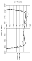
16 is a graph of a comparison test.
본 발명의 실시 형태를 첨부 도면을 참조로 설명한다. 본 실시예에서, 화상 형성 장치는 예로서 전자 사진 프로세스를 이용한 레이저 빔 프린터이다. 이 레이저 빔 프린터를 간단히 프린터라 칭한다.Embodiments of the present invention will be described with reference to the accompanying drawings. In this embodiment, the image forming apparatus is a laser beam printer using an electrophotographic process as an example. This laser beam printer is simply referred to as a printer.
[실시예 1][Example 1]
[화상 형성 장치][Image Forming Apparatus]
도 1은, 본 실시예의 화상 형성 장치인 프린터(1)의 단면도이다. 프린터(1)는 화상 형성 스테이션(10)과 정착 장치(40)를 포함하고, 감광 드럼(11)에 형성한 토너 화상이 시트 P에 전사되고 시트 P에 정착되어, 시트 P에 화상이 형성된다. 도 1을 참조하여 장치의 구성을 상세하게 설명한다.1 is a sectional view of the
도 1에 도시한 바와 같이, 프린터(1)는 Y(옐로우), M(마젠타), C(시안), Bk(블랙)의 각 색의 토너 화상을 형성하는 화상 형성 스테이션(10)을 구비하고 있다. 화상 형성 스테이션(10)은 좌측부터 순서대로 Y, M, C, Bk의 색에 대응한 각각의 감광 드럼(11)(11Y, 11M, 11C, 11Bk)을 구비하고 있다. 각 감광 드럼(11)의 주위에는 다음과 같은 유사한 요소들이 제공된다: 대전기(12)(12Y, 12M, 12C, 12Bk); 노광 장치(13)(13Y, 13M, 13C, 13Bk); 현상 장치(14)(14Y, 14M, 14C, 14Bk); 1차 전사 블레이드(17)(17Y, 17M, 17C, 17Bk) 및 클리너(15)(15Y, 15M, 15C, 15Bk). Bk색의 토너 화상을 형성하는 구성에 대해서 대표해서 설명하고, 타색에 대해서는 동일한 기호를 사용해서 기재해서 그 설명을 생략한다. 따라서, 상기 요소들은 감광 드럼(11), 대전기(12), 노광 장치(13), 현상 장치(14), 1차 전사 블레이드(17), 클리너(15)이라고 칭한다.1, the
전자 사진 감광체로서의 감광 드럼(11)은 구동원(도시하지 않음)에 의해 화살표 방향(도 1의 반시계 방향)으로 회전한다. 감광 드럼(11)의 주위에는, 대전기(12), 노광 장치(13), 현상 장치(14), 1차 전사 블레이드(17) 및 클리너(15)가 기재 순서대로 제공된다.The
감광 드럼(11)의 표면은 대전기(12)에 의해 전기적으로 대전된다. 그후, 감광 드럼(11)은 화상 정보에 따라서 노광 장치(13)에 의해 레이저 빔에 노광되어, 정전 잠상이 형성된다. 이 정전 잠상은, 현상 장치(14)에 의해 Bk색의 토너 화상이 된다. 이때 다른 색에 대해서도 마찬가지의 공정이 행해진다. 토너 화상은 감광 드럼(11)으로부터 1차 전사 블레이드(17)에 의해, 중간 전사 벨트(31)에 순차적으로 전사된다(1차 전사). 1차 전사 후, 감광 드럼(11)에 남은 토너는, 클리너(15)에 의해 제거된다. 이렇게 해서, 감광 드럼(11)의 표면은 다음 화상을 위해 준비되도록 청정해진다.The surface of the
한편, 급송 카세트(20) 또는 멀티 급송 트레이(25)에 놓인 시트 P는, 급송 기구(도시하지 않음)에 의해 픽업되고 한 쌍의 정합 롤러에 급송된다. 시트 P는 그 표면에 화상이 형성되는 부재이다. 시트 P의 구체적 예로서, 보통지, 두꺼운 종이, 수지제 시트, 영사기용 필름 등이 있다. 정합 롤러 쌍(23)은 사행 급송을 교정하기 위해 시트 P를 일단 정지시킨다. 그후, 정합 롤러(23)는 중간 전사 벨트(31) 상의 토너 화상과 동기화하여, 시트 P를 중간 전사 벨트(31)와 2차 전사 롤러(35)의 사이로 급송한다. 롤러(35)는 벨트(31)로부터의 컬러의 토너 화상을 시트 P에 전사한다. 그 후, 시트 P는 정착장치(화상 가열 장치)(40)로 급송된다. 정착장치(40)는 시트 P상의 토너 화상 T 를 가열, 가압해서 시트 P에 정착한다.On the other hand, the sheet P laid on the
[정착장치][Fixing device]
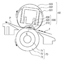
프린터(1)에 사용되는 화상 가열 장치인 정착장치(40)에 대해서 설명한다. 도 2는 정착장치(40)의 단면도이다. 도 3은 정착장치(40)의 정면도이다. 도 5는 정착장치(40)의 구성 관계를 예시한다.A fixing
정착장치(40)는, 히터 유닛(60)(유닛(60))에 의해 시트상의 화상을 가열하는 화상 가열 장치이다. 유닛(60)은 가요성의 얇은 정착 벨트(603)와, 벨트(603)를 가열하기 위해 벨트(603)의 내면에 접촉하는 히터(600)를 포함한다(저 열용량 구조). 따라서, 벨트(603)을 효율적으로 가열할 수 있고, 정착 개시 시의 신속한 온도 상승이 달성된다. 도 2에 도시한 바와 같이, 벨트(603)는 히터(600)와 가압 롤러(70)(롤러(70))에 끼움 지지되고, 이에 의해, 닙부 N이 형성된다. 벨트(603)는 화살표 방향(시계 방향, 도 2)으로 회전하고, 롤러(70)는 화살표 방향(반시계 방향, 도 2)(29)으로 회전하여, 닙부 N에 공급된 시트 P를 끼움 지지해서 급송한다. 이때, 히터(600)의 열이 벨트(603)를 통해 시트 P에 부여되기 때문에 시트 P상의 토너 화상 T는 닙부 N에서 가열 및 가압되고, 그래서, 이 열 및 압력에 의해 토너 화상이 시트 P에 정착된다. 정착 닙부 N을 통과한 시트 P는 벨트(603)로부터 분리되어 배출된다. 본 실시예에서, 상술한 바와 같이 해서 정착 처리가 행하여진다. 정착장치(40)의 구성에 대해서 상세하게 설명한다.The fixing
유닛(60)은 시트 P상의 화상을 가열 및 가압하기 위한 유닛이다. 유닛(60)의 길이 방향은 롤러(70)의 길이 방향과 평행하다. 유닛(60)은 히터(600)와, 히터 홀더(601)와, 지지 스테이(602)와, 벨트(603)를 구비하고 있다.The
히터(600)는 벨트(603)의 내면에 미끄럼이동가능하게 접촉해서 벨트(603)을 가열하는 가열 부재이다. 히터(600)는 닙부 N의 폭이 원하는 폭이 되게, 벨트(603)를 그 내면측으로부터 롤러(70)를 향해서 가압한다. 본 실시예에서, 히터(600)의 치수는 폭(도 2의 좌우 방향으로 측정된 치수)이 5 내지 20mm이고, 길이(도 2의 전후 방향으로 측정된 치수)가 350 내지 400mm이며, 두께가 0.5 내지 2mm이다. 히터(600)는 시트 P의 급송 방향에 직교하는 방향(시트 P의 폭 방향)으로 세장형인 기판(610)과, 저항 발열체(620)(발열체(620))를 구비하고 있다.The
히터(600)는 히터 홀더(601)의 하면에 히터 홀더(601)의 길이 방향을 따라서 고정되어 있다. 본 실시예에서, 벨트(603)와 미끄럼 접촉하지 않는 기판(610)의 이면측에 발열체(620)가 제공되어 있지만, 발열체(620)는 벨트(603)와 활주 접촉하는 기판(610)의 전면측에 제공될 수 있다. 그러나, 발열체(620)의 비 발열부에 의해 유발되는 비균일 열적용을 방지하기 위한 견지에서 기판(610)의 균일한 가열 효과가 얻어지는 기판(610)의 이면 측에 발열체(620)를 제공하는 구성이 바람직하다. 히터(600)의 세부 사항을 후술한다.The
벨트(603)는 시트상의 화상을 닙부 N에서 가열하는 원통 형상(엔드리스)의 벨트(필름)이다. 벨트(603)는 예를 들어 기재(603a)와, 기재 위의 탄성층(603b)과, 탄성층(603b) 위의 이형층(603c)을 포함한다. 기재(603a)는 스테인리스나 니켈 등의 금속재료나, 폴리이미드 등의 내열 수지 등이 사용된다. 탄성층(603b)은 실리콘 고무, 불소 함유 고무 등의 탄성 및 내열성을 갖는 재료로 이루어질 수 있다. 이형층(603c)은 불소 수지나 실리콘 수지로 이루어질 수 있다.The
본 실시예의 벨트(603)는 외경이 약 30mm, 길이(도 2의 전후방향으로 측정된 치수)가 약 330mm, 두께가 약 30㎛인 치수를 가지고, 기재(603a)의 재료는 니켈이다. 기재(603a) 위에 두께 약 400㎛의 실리콘 고무의 탄성층(603b)이 형성되고, 두께 약 20㎛의 불소 수지 튜브(이형층(603c))가 탄성층(603b)을 피복하고 있다.The
기판(610)의 벨트 접촉면은 활주층(603d)으로서 두께 약 10㎛의 폴리이미드 층이 제공될 수 있다. 폴리이미드층을 설치한 경우, 정착 벨트(603)와 히터(600)의 사이의 마찰 저항을 저감해서 벨트(603) 내면의 마모를 억제할 수 있다. 또한 활주성을 높이기 위해서, 벨트 내면에 그리스 등의 윤활제가 도포될 수 있다.The belt contact surface of the
히터 홀더(601)(홀더(601))는 히터(600)를 벨트(603)의 내면을 향해서 가압한 상태로 히터(600)를 보유하는 역할을 한다. 홀더(601)는 반원호 형상 단면(도 2의 표면)을 가지며, 벨트(603)의 회전 궤도를 규제하는 역할을 한다. 홀더(601)는 내열성의 수지 등으로 이루어질 수 있다. 본 예에서, 이는 듀퐁사의 Zenite 7755(상품명)이다.The heater holder 601 (holder 601) serves to hold the
지지 스테이(602)는 홀더(601)를 거쳐서 히터(600)를 지지한다. 지지 스테이(602)는 높은 압력이 인가되어도 쉽게 변형되지 않는 재료로 이루어지는 것이 바람직하며, 본 예에서, 이는 SUS304(스테인리스강)으로 이루어진다.The
도 3에 도시한 바와 같이, 지지 스테이(602)는 그 길이 방향의 양 단부에서, 좌우의 플랜지(411a, 411b)에 지지되고 있다. 플랜지들(411a, 411b)은 간단히 플랜지(411)라 지칭될 수 있다. 플랜지(411)는 벨트(603)의 길이 방향 이동 및 벨트(603)의 둘레 방향의 구조를 규제하고 있다. 플랜지(411)는 내열성의 수지 등으로 이루어진다. 본 실시예에서는 이는 PPS(폴리페닐렌술피드)이다.As shown in Fig. 3, the
플랜지(411a)와 가압 아암(414a)의 사이에는 가압 스프링(415a)이 압축된다. 또한, 플랜지(411b)와 가압 아암(414b)의 사이에도 가압 스프링(415b)이 압축된다. 가압 스프링들(415a, 415b)은 간단히 가압 스프링(415)이라 지칭될 수 있다. 이와 같은 구성에 의해, 플랜지(411) 및 지지 스테이(602)를 거쳐 가압 스프링(415)의 탄성력이 히터(600)에 전해진다. 벨트(603)는 롤러(70)의 상면에 대하여 소정의 가압력으로 가압되어, 소정 니부 폭을 갖는 닙부 N가 형성된다. 본 실시예에서 가압력은 일단부측이 약 156.8N이고, 총가압력이 약 313.6N(32 kgf)이다.A
도 3에 도시한 바와 같이, 커넥터(700)는 히터(600)에 급전을 행하기 위해서 히터(600)와 전기적으로 접속된 급전 부재로서 제공된다. 커넥터(700a, 700b)는 간단히 커넥터(700)라 지칭된다. 커넥터(700)는 히터(600)의 길이 방향 일단부 측에 착탈가능하게 설치된다. 커넥터(700)는 히터(600)의 길이방향 타단부에 착탈가능하게 제공된다. 커넥터(700)는 히터(600)에 대하여 쉽게 착탈가능하게 설치되며, 따라서, 정착장치(40)의 조립이나, 히터(600) 손상시 벨트(603) 나 히터(600)의 교환이 용이하며, 따라서, 양호한 유지 보수성을 제공한다. 커넥터(700)의 세부사항을 후술한다.As shown in Fig. 3, the connector 700 is provided as a power supply member electrically connected to the
도 2에 도시한 바와 같이, 롤러(70)는 벨트(603)의 외면에 접촉함으로써 벨트(603)과 협동해서 닙부 N을 형성하는 닙 형성 부재이다. 롤러(70)는 금속제의 코어 금속 상의 다층 구조를 가지며, 이 다층 구조는 코어 금속(71) 상의 탄성층(72), 탄성층(72) 위의 이형층(73)을 포함한다. 코어 금속(71)의 재료 예는 SUS(스테인리스강), SUM(황 및 황 복합 쾌삭강 강재), Al(알루미늄) 등을 포함한다. 탄성층(72)의 재료 예는 탄성 솔리드 고무층, 탄성 발포 고무층, 탄성 다공성 고무층 등을 포함한다. 이형층(73)의 재료 예는 불소 수지 재료를 포함한다.2, the
본 실시예의 롤러(70)는 철제의 코어 금속과, 코어 금속(71) 상의 발포 실리콘 고무의 탄성층(72)과, 탄성층(72) 상의 불소 수지 튜브의 이형층(73)을 포함한다. 롤러(70)의 탄성층(72) 및 이형층(73)을 갖는 부분의 치수는 외경이 약 25mm이고, 길이가 약 330mm이다.The
서미스터(630)는 히터(600)의 이면측(활주 표면측의 반대측)에 설치된 온도 센서이다. 서미스터(630)는 발열체(620)로부터 절연된 상태에서 히터(600)에 결합된다. 서미스터(630)는 히터(600)의 온도를 검지하는 기능을 갖는다. 도 5에 도시한 바와 같이, 서미스터(630)는 A/D 컨버터(도시하지 않음)를 통해 제어 회로(100)와 접속되어 있고, 검지한 온도에 따른 출력을 제어 회로(100)에 송신한다.The
제어 회로(100)는 각종 제어를 위해 동작하는 CPU와, 각종 프로그램을 기억한 ROM 등의 불휘발성 매체를 구비한 회로를 포함한다. 이 ROM에는 프로그램이 기억되고, CPU가 이것을 판독해서 실행함으로써, 각종 제어를 실행한다. 제어 회로(100)는 유사한 동작을 수행할 수 있으면 ASIC 등의 집적 회로일 수 있다.The
도 5에 도시한 바와 같이, 제어 회로(100)는 전원(110)의 전력 공급을 제어하도록 전원(110)과 전기적으로 접속되어 있다. 제어 회로(100)는 서미스터(630)의 출력을 취득하도록 서미스터(630)에 전기적으로 접속되어 있다. 제어 회로(100)는 서미스터(630)로부터 취득한 온도 정보를 전원(110)의 급전 제어에 사용한다. 특히, 제어 회로(100)는 서미스터(630)의 출력을 바탕으로, 전원(110)을 을 통해 히터(600)에 공급하는 전력을 제어하고 있다. 본 실시예에서 제어 회로(100)가 전원(110)의 출력 파수 제어를 행함으로써, 히터(600)의 발열량을 조정한다. 이러한 제어를 행함으로써, 히터(600)는 소정의 온도(예를 들어, 약 180℃)로 일정하게 유지된다.As shown in Fig. 5, the
도 3에 도시한 바와 같이, 롤러(70)의 코어 금속(71)은 각각 측판(41)의 후방측과 전방측에 제공된 베어링(41a, 41b)에 의해 회전가능하게 보유되어 있다. 또한, 코어 금속의 축선 방향의 일 단부에는 기어 G가 설치되어 모터 M의 구동력을 롤러(70)의 코어 금속(71)에 전달한다. 도 2에 도시한 바와 같이, 모터 M으로부터의 구동력을 전달받은 롤러(70)는 화살표 방향(시계 방향)으로 회전한다. 닙부 N에서, 롤러(70)에 의해 벨트(603)에 구동력이 전달됨으로써, 벨트(603)가 화살표 방향(반시계 방향)으로 회전된다.3, the
모터 M은, 기어 G를 통해서 롤러(70)를 구동하는 구동부이다. 도 5에 도시한 바와 같이, 제어 회로(100)는 모터 M의 급전을 제어하기 위해서 모터 M에 전기적으로 접속되어 있다. 제어 회로(100)의 제어에 의해 전기 에너지가 공급되면, 모터 M는 기어 G를 회전시키기 시작한다.The motor M is a drive unit that drives the
제어 회로(100)는 모터 M의 회전을 제어한다. 제어 회로(100)는 모터 M를 사용하여 롤러(70)와 벨트(603)를 소정의 속도로 회전시킨다. 이는 정착 처리 작업에서 닙부 N에서 끼움 지지 및 반송되는 시트 P의 속도가, 소정의 프로세스 스피드(예를 들어, 약 200[mm/sec])와 같도록 모터를 제어한다.The
[히터][heater]
정착장치(40)에 사용되는 히터(600)의 구성을 상세하게 설명한다. 도 4는 실시예 1의 히터의 구성을 예시한다. 도 6은 커넥터를 예시한다. 도 14의 부분 (a)은 히터(600)에 사용되는 발열 방식을 예시한다. 도 14의 부분 (b)는 히터(600)에 사용되는 발열 영역의 전환 방식을 예시한다.The configuration of the
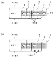
본 실시예의 히터(600)은 도 14의 부분 (a) 및 (b)에 예시된 발열 방식을 사용하는 히터이다. 도 14의 부분 (a)에 도시한 바와 같이, A 배선에는 제1 내지 제3 전극이 접속되어 있고, B 배선에는 제4 내지 제6 전극이 접속되어 있다. A 배선에 접속된 전극과 B 배선에 접속된 전극은 길이 방향(도 14의 부분 (a)의 좌우 방향)을 따라 간삽(교번적으로 배열)되어 있고, 발열체가 인접한 전극들 사이에 전기적으로 접속되어 있다. A 배선과 B 배선의 사이에 전압 V가 인가되면, 인접하는 전극의 사이에는 전위차가 발생한다. 결과적으로, 발열체를 통해 전류가 흐르고, 인접하는 발열체 사이의 전류는 서로 반대이다. 이러한 유형의 히터에서, 상술한 방식으로 열이 발생된다. 도 14의 부분(b)에 도시된 바와 같이, B 배선과 제6 전극의 사이에 스위치 등이 제공되며, 스위치가 개방되면, 제2 전극과 제6 전극은 동일 전위이므로, 그 사이의 발열체에는 전류가 흐르지 않게 된다. 이러한 시스템에서, 길이 방향으로 배열된 발열체는 독립적으로 통전이 이루어지고, 그래서, 일부를 오프 상태로 절환함으로써 발열체의 일부만이 통전될 수 있다. 즉, 이러한 시스템에서, 발열 영역은 배선에 스위치 등을 설치함으로써 변경될 수 있다. 히터(600)에서, 발열체(620)의 발열 영역은 상술한 시스템을 사용하여 변경될 수 있다.The
발열체는 통전시 전류의 방향에 관계없이 발열하지만, 길이 방향을 따른 방향으로 전류가 흐르도록 발열체와 전극을 배치하는 것이 바람직하다. 이런 배열은 전류의 방향이 길이 방향(도 11의 부분 (a)의 상하방향)에 수직인 폭 방향인 배열에 비해 이하의 관점에서 유리하다. 발열체에 통전해서 주울 발열을 시킬 경우, 발열체는 그 저항값에 따른 발열을 행하며, 따라서, 발열체는 저항값이 원하는 값이 되도록 전류의 방향에 따라서 치수 및 재질이 선택된다. 발열체를 설치하는 기판의 치수는, 길이 방향에 비하여 폭 방향으로 매우 짧다. 그로 인해, 폭 방향으로 전류를 흘리는 경우, 저저항의 재료를 사용해서 발열체에 원하는 저항값을 제공하는 것이 곤란하다. 한편, 길이 방향으로 전류를 흘리는 경우, 저 저항의 재료를 사용해서 발열체에 원하는 저항값을 갖게 하는 것이 비교적 용이하다. 또한, 발열체에 고저항의 재료를 사용하는 경우, 통전시 발열체의 두께 비균일성에 의해 온도 비균일성을 초래할 우려가 있다. 예를 들어, 스크린인쇄 등에 의해 기판의 길이 방향을 따라서 발열체 재료를 도포하는 경우, 폭 방향으로 약 5%의 두께 비균일성이 초래될 수 있다. 이는 도장 블레이드에 의한 폭 방향의 작은 압력 편차에 기인하여 발열체 재료의 도장 불균일성이 발생하기 때문이다. 따라서, 길이 방향으로 통전하게 발열체와 전극을 배치하는 것이 바람직하다.It is preferable to dispose the heating element and the electrode so that the current flows in the direction along the longitudinal direction, though the heating element generates heat irrespective of the direction of the current upon energization. This arrangement is advantageous in view of the following in comparison with the arrangement in which the direction of the current is in the width direction perpendicular to the longitudinal direction (the up-and-down direction of the portion (a) in Fig. 11). When the joule heat is generated by energizing the heating element, the heating element generates heat in accordance with the resistance value, and accordingly, the heating element is selected in dimensions and materials according to the direction of the current so that the resistance value becomes a desired value. The size of the substrate on which the heat generating element is mounted is very short in the width direction as compared with the longitudinal direction. Therefore, when a current flows in the width direction, it is difficult to provide a desired resistance value to the heating element by using a low resistance material. On the other hand, when a current flows in the longitudinal direction, it is relatively easy to make the heating element have a desired resistance value by using a low resistance material. In addition, when a material having a high resistance is used for the heating element, there is a fear that temperature ununiformity is caused by nonuniform thickness of the heating element at the time of energization. For example, when the heating material is applied along the longitudinal direction of the substrate by screen printing or the like, thickness nonuniformity of about 5% in the width direction may be caused. This is because coating irregularity of the heating body material occurs due to a small pressure deviation in the width direction by the coating blades. Therefore, it is preferable to dispose the heating element and the electrode in the longitudinal direction.
길이 방향으로 배열된 발열체에 개별적으로 통전을 행하는 경우, 인접하는 발열체에서 흐르는 전류의 방향이 엇갈리게 되도록 발열체와 전극을 배치하는 것이 바람직하다. 발열체와 전극의 배열에 대하여, 양단에서 전극과 각각 접속된 발열체를 길이방향으로 배열하고 길이 방향으로 전력을 공급하는 것을 고려할 수 있다. 그러나, 이 배열에서는 인접하는 발열체간에 2개의 전극이 제공되어 단락의 우려가 있다. 또한, 필요한 전극의 수가 증가하고, 인접한 발열체 사이에 큰 비 발열부가 발생된다. 따라서, 인접하는 발열체 사이에 전극이 공용되도록 발열체와 전극을 배치하는 것이 바람직하다. 이 배열에 의해, 전극간에서의 단락의 우려를 해소하고, 또한, 비 발열부를 작게 할 수 있다.It is preferable to dispose the heating element and the electrodes so that the directions of the currents flowing in the adjacent heating elements are shifted when individually energizing the heating elements arranged in the longitudinal direction. Regarding the arrangement of the heating element and the electrodes, it is conceivable that the heating elements connected to the electrodes at both ends are arranged in the longitudinal direction and power is supplied in the longitudinal direction. However, in this arrangement, two electrodes are provided between adjacent heating elements, which may cause a short circuit. In addition, the number of necessary electrodes increases, and a large non-heating portion is generated between adjacent heating elements. Therefore, it is preferable to arrange the heating element and the electrode so that the electrodes are shared between the adjacent heating elements. With this arrangement, the possibility of a short circuit between the electrodes can be solved, and the non-heating portion can be made smaller.
본 실시예에서, 도 14의 부분 (a)의 A 배선에 상당하는 것이 공통 배선(640)이며, B 배선에 상당하는 것이 대향 배선(650, 660a, 660b)이다. 또한, 도 14의 부분 (a)의 제1 내지 제3 전극에 상당하는 것이 공통 전극(642a 내지 642g)이며, 제4 내지 제6 전극에 상당하는 것이, 대향 전극(652a 내지 652d, 662a, 662b)이다. 도 14의 부분 (a)의 발열체에 상당하는 것이 발열체(620a 내지 620l)이다. 이후, 공통 전극(642a 내지 642g)를 간단히 공통 전극(642)이라 칭한다. 대향 전극(652a 내지 652e)을 간단히 대향 전극(652)이라 칭한다. 대향 전극(652a 내지 652e)를 간단히 대향 전극(652)이라 칭한다. 대향 배선(660a, 660b)를 간단히 대향 배선(660)이라 칭한다. 발열체(620a 내지 620l)를 간단히 발열체(620)라 칭한다. 히터(600)의 구성에 대해서 도면을 사용해서 상세하게 설명한다.In this embodiment, the
도 4 및 도 6에 도시한 바와 같이, 히터(600)는 기판(610)과, 기판(610) 상의 발열체(620)와, 도체의 패턴(배선)과, 발열체(620)와 도체의 패턴(배선)을 덮는 절연 코트층(680)을 구비하고 있다.4 and 6, the
기판(610)은 히터(600)의 치수나 구성을 결정하며, 기판(610)의 길이 방향을 따라서 벨트(603)에 접촉가능하다.The
기판(610)의 재료는 내열성, 열전도성, 전기 절연성 등이 우수한 알루미나, 질화 알루미늄 등의 세라믹 재료이다. 본 실시예에서는 길이(도 4의 좌우 방향으로 측정됨)가 약 400mm, 폭(도 4의 상하 방향으로 측정됨)이 약 8mm, 두께가 약 1mm인 알루미나의 판 부재이다.The material of the
기판(610)의 이면 상에는, 도전성 후막 페이스트를 사용해서 후막인쇄법(스크린인쇄법)에 의해 발열체(620)와 도체 패턴(배선)이 제공된다. 본 실시예에서, 도체 패턴에는 저항률이 낮아지도록 은 페이스트가 사용되고, 발열체(620)에는 저항률이 높아지도록 은-팔라듐 합금의 페이스트가 사용되고 있다. 도 6에 도시한 바와 같이, 발열체(620)와 도체의 패턴은, 내열성 유리로 이루어지는 절연 코트층(680)에 의해 피복되어 있어, 누설이나 단락으로부터 전기적으로 보호되고 있다.On the back surface of the
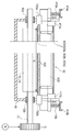
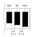
도 4에 도시한 바와 같이, 기판(610)의 길이 방향 일단부에는, 도체 패턴의 일부로서의 전기접점(641)이 설치된다. 길이방향으로 기판(610)의 타단부측(610b)에는, 도체 패턴의 일부로서 전기접점(651, 661a, 661b)이 제공된다. 길이방향으로 기판(610)의 중앙 영역(610c)에는 발열체(620)와 도체 패턴의 일부로서의 대향 전극(652, 662) 및 공통 전극(642)이 제공된다. 폭 방향에 관하여 발열체(620)를 초과한 기판(610)의 일단부측(610d)에는, 도체 패턴의 일부로서의 공통 배선(640)이 설치된다. 폭 방향에 관하여 발열체(620)를 초과한 기판(610)의 타단부측(610e)에는, 도체 패턴의 일부로서의 대향 배선(650, 660)이 설치된다.As shown in Fig. 4, at one longitudinal end portion of the
발열체(620)(620a 내지 620l)는 급전시 줄 열을 발생하는 저항체이다. 발열체(620)는 기판(610) 위로 길이 방향으로 연장하는 1개의 발열체이며, 기판(610)의 중앙 부근의 영역(610c)(도 4)에 배치된다. 발열체(620)는 원하는 저항값을 가지며, 1 내지 4mm의 폭(기판(610)의 폭 방향으로 측정됨) 및 5 내지 20㎛의 두께를 갖는다. 본 실시예의 발열체(620)는 폭이 약 2mm이고, 두께가 약 10㎛이다. 발열체(620)의 길이 방향 총 길이는 약 320mm이며, 이는 A4사이즈(폭 약 297mm)의 시트 P의 폭에 작용되기에 충분하다.The heat generating elements 620 (620a to 620l) are resistors that generate heat in the feed line. The
발열체(620) 상에는 후술하는 7개의 공통 전극(642a 내지 642g)이 길이 방향으로 간격을 두고 적층되어 있다. 환언하면, 발열체(620)는 공통 전극(642a 내지 642g)에 의해 길이 방향으로 6개의 구간으로 격리되어 있다. 각 구간의 기판(610)의 길이 방향으로 측정된 길이는 약 53.3mm이다. 발열체(620)의 각 구간의 중앙부에는 6개의 대향 전극(652, 662)(652a 내지 652d, 662a, 662b) 중 1개가 적층되어 있다. 이렇게 해서, 발열체(620)는 12개의 소 구간으로 분할된다. 12개의 소 구간으로 분할된 발열체(620)는 복수의 발열체(620a 내지 620l)로 간주할 수 있다. 달리 말하면, 복수의 발열체(620a 내지 620l)는 인접하는 전극을 서로 전기적으로 접속한다. 기판(610)의 길이 방향으로 측정된 소 구간의 길이는 약 26.7mm이다. 발열체(620)의 소 구간의 길이 방향 저항값은 약 120Ω다. 이와 같은 구성에 의해, 발열체(620)는 길이 방향에 관하여 부분적 영역 또는 영역들에서 발열할 수 있다.Seven
발열체(620)의 길이 방향의 저항률은 균일하고, 발열체(620a 내지 620l)는 대략 동등한 치수를 갖는다. 그로 인해, 각 발열체(620a 내지 620l)의 저항값은 실질적으로 동등하다. 병렬로 급전되는 경우, 발열체(620)의 발열 분포는 균일하다. 그러나, 발열체(620a 내지 620l)가 실질적으로 동등한 치수 및/또는 실질적으로 동등한 저항률을 가지는 것이 필수적인 것은 아니다. 예를 들어, 발열체(620)의 길이방향 단부에서의 온도 저하를 방지하도록 발열체(620a와 620l)의 저항값이 조절될 수 있다. 공통 전극(642) 및 대향 전극(652, 662)이 형성된 발열체(620) 상의 위치에서, 발열체(620)의 발열은 실질적으로 0이다. 그러나, 전극의 폭을 1mm 이하로 억제하는 경우, 기판(610)의 가열 균일화 기능에 의해 정착 처리에 대한 영향을 무시할 수 있게 된다. 본 실시예의 각 전극의 폭은 1mm 이하이다.The resistivity in the longitudinal direction of the
공통 전극(642)(642a 내지 642g)은 상술한 도체 패턴의 일부이다. 공통 전극(642)은 발열체(620)의 길이 방향과 직교하는 기판(610)의 폭 방향으로 연장한다. 본 실시예에서 공통 전극(642)은 발열체(620) 상에 적층된다. 공통 전극(642)은 발열체(620)에 접속된 전극 중, 발열체(620)의 길이 방향 일단부로부터 셀 때 홀수 번째의 전극들이다. 공통 전극(642)은 후술하는 공통 배선(640) 등을 통해 전원(110)의 일 접점(110a)에 접속되어 있다.The common electrodes 642 (642a to 642g) are part of the conductor pattern described above. The common electrode 642 extends in the width direction of the
대향 전극(652, 662)은, 상술한 도체 패턴의 일부이다. 대향 전극(652, 662)은 발열체(620)의 길이 방향과 직교하는 기판(610)의 폭 방향으로 연장한다. 대향 전극(652, 662)은 발열체(620) 상에 적층된다. 대향 전극(652, 662)은 발열체(620)에 접속된 전극 중, 상술한 공통 전극(642)이외의 전극이다. 즉, 본 실시예에서, 발열체(620)의 길이 방향 일단부로부터 셀 때, 짝수 번째 전극들이다.The counter electrodes 652 and 662 are part of the conductor pattern described above. The opposing electrodes 652 and 662 extend in the width direction of the
즉, 공통 전극(642)과 대향 전극(662, 652)은 발열체의 길이 방향으로 교대로 배열된다. 대향 전극(652, 662)은 후술하는 대향 배선(650, 660)을 통해 전원(110)의 다른 접점(110b)에 접속되어 있다.That is, the common electrode 642 and the opposing electrodes 662 and 652 are alternately arranged in the longitudinal direction of the heat generating element. The counter electrodes 652 and 662 are connected to the
공통 전극(642) 및 대향 전극(652, 662)은 발열체(620)에 급전을 위한 복수의 전극부로서 기능한다. 본 실시예에서, 홀수 번째 전극들이 공통 전극(642)이고, 짝수 번째 전극들이 대향 전극(652, 662)이지만, 히터(600)의 구조는 이러한 예에 한정되지 않는다. 예를 들어, 짝수 번째 전극들이 공통 전극(642)이고, 홀수 번째 전극들이 대향 전극(652, 662)일 수 있다.The common electrode 642 and the counter electrodes 652 and 662 function as a plurality of electrode portions for feeding the
또한, 본 실시예에서, 발열체(620)에 접속된 모든 대향 전극 중에 4개가 대향 전극(652)이다. 본 실시예에서, 발열체(620)에 접속된 모든 대향 전극 중에 2개가 대향 전극(662)이다. 그러나, 대향 전극의 배당은 본 실시예에 한정되지 않고, 히터(600)의 발열 폭에 따라서 변경될 수 있다. 예를 들어, 대향 전극(652)이 2개, 대향 전극(662)이 4개일 수 있다.In this embodiment, four of the counter electrodes connected to the
공통 배선(640)은 상술한 도체 패턴의 일부이다. 공통 배선(640)은 기판의 일단부측(610d)에서 기판(610)의 길이 방향을 따라서 기판의 일단부측(610a)을 향해 연장한다. 공통 배선(640)은 발열체(620)(620a 내지 620l)에 접속된 공통 전극(642)(642a 내지 642g)에 접속되어 있다. 공통 배선(640)은 후술하는 전기접점(641)에 접속되어 있다. 본 실시예에서는, 절연 코트층(680)의 절연을 보증하기 위해, 공통 배선(640)과 각 대향 전극과의 사이에 약 400㎛의 간격을 설정하고 있다.The
대향 배선(650)은 상술한 도체 패턴의 일부이다. 대향 배선(650)은 기판의 타단부측(610e)에서 기판(610)의 길이 방향을 따라서 기판의 다른 단부(610b)를 향해 연장한다. 대향 배선(650)은 발열체(620)(620c 내지 620j)에 접속된 대향 전극(652)(652a 내지 652d)에 접속되어 있다. 대향 배선(650)은 후술하는 전기접점(651)에 접속되어 있다.The
대향 배선(660)(660a, 660b)은 상술한 도체 패턴의 일부이다. 대향 배선(660a)은 기판의 타단부측(610e)에서 기판(610)의 길이 방향을 따라서 기판의 다른 단부(610a)를 향해 연장한다. 대향 배선(660a)은 발열체(620)(620a, 620b)에 접속된 대향 전극(662a)에 접속되어 있다. 대향 배선(660a)은 후술하는 전기접점(661a)에 접속되어 있다. 대향 배선(660b)은 기판의 타단부측(610e)에서 기판(610)의 길이 방향을 따라서 기판의 다른 단부(610b)를 향해 연장한다. 대향 배선(660b)은 발열체(620)(620k, 620l)에 접속된 대향 전극(662a)에 접속되어 있다. 또한, 대향 배선(660b)은 후술하는 전기접점(661b)에 접속되어 있다. 본 실시예에서, 절연 코트층(680)에 의한 절연을 보증하기 위해, 대향 배선(660b)과 공통 전극(642)의 사이에 약 400㎛의 간격이 제공된다. 또한, 대향 배선(660a와 650)의 사이 및 대향 배선(600b와 650)의 사이에는 약 100㎛의 간격이 제공된다.The counter wiring 660 (660a, 660b) is a part of the above-described conductor pattern. The
전기접점(641, 651, 661a, 661b)은 상술한 도체 패턴의 일부이다. 기판의 일 단부측(610a)에 전기접점이 제공된다. 기판의 타탄부측(610b)에 전기 접점(651, 661a, 661b)이 제공된다. 도 6에 도시된 바와 같이, 전기접점(641, 651, 661a, 661b)을 포함하는 부분은 절연 코트층(680)으로 피복되어 있지 않아서 전기접점(641, 651, 661a, 661b)이 노출된다. 따라서, 전기접점(641)은 커넥터(700a)와 접촉하고 전기적으로 접속될 수 있다. 전기 접점(651, 661a, 661b)은 커넥터(700b)와 접촉하고 전기적으로 접속될 수 있다.The
히터(600)와 커넥터(700) 사이의 접속을 통해 전기접점(641)과 전기접점(651)의 사이에 전압이 인가된 경우, 공통 전극(642)(642b 내지 642f)과 대향 전극(652)(652a 내지 652d)의 사이에 전위차가 발생한다. 그로 인해, 발열체(620c, 620d, 620e, 620f, 620g, 620h, 620i, 620j)를 통해, 기판(610)의 길이 방향을 따라 전류가 흐르며, 인접한 발열체를 통한 전류의 방향은 서로 실질적으로 반대이다. 제1 발열 영역으로서의 발열체(620c, 620d, 620e, 620f, 620g, 620h, 620i)가 각각 발열한다. When a voltage is applied between the
히터(600)와 커넥터(700) 사이의 접속을 통해, 전기접점(641)과 전기접점(661a)의 사이에 전압이 인가된 경우, 공통 전극(642a 내지 642b)과 대향 전극(662a)의 사이에 전위차가 발생한다. 그로 인해, 발열체(620a, 620b)를 통해, 기판(610)의 길이 방향을 따라 전류가 흐르며, 인접한 발열체를 통한 전류의 방향은 실질적으로 서로 반대이다. 제2 발열 영역으로서의 발열체(620a, 620b)가 발열한다.When a voltage is applied between the
히터(600)와 커넥터(700) 사이의 접속을 통해, 전기접점(641)과 전기접점(661b)의 사이에 전압이 인가된 경우, 공통 배선(640) 및 대향 배선(660b)을 통해 공통 전극(642f 및 642g)과 대향 전극(662a)의 사이에 전위차가 발생한다. 그로 인해, 발열체(620k, 620l)를 통해, 기판(610)의 길이 방향을 따라 전류가 흐르며, 인접하는 발열체를 통한 전류의 방향은 실질적으로 서로 반대이다. 제3 발열 영역으로서의 발열체(620k, 620l)가 각각 발열한다.When a voltage is applied between the
이러한 방식으로, 전압이 공급되는 전기접점을 선택함으로써, 발열체(620a 내지 620l) 중에서 원하는 발열체 또는 발열체들에 선택적으로 통전할 수 있다.In this way, by selecting the electrical contact to which the voltage is supplied, it is possible to selectively energize a desired heating element or heating elements among the
[커넥터][connector]
정착장치(40)에 사용되는 커넥터(700)를 상세하게 설명한다. 도 7은 콘텍트 단자를 예시한다. 본 실시예의 커넥터(700a, 700b)는 히터(600)에 대한 장착에 의해 히터(600)와 전기적으로 접속된다. 도 6에 도시된 바와 같이, 커넥터(700a)는 전기 접점(641)과 전기적으로 접속될 수 있는 콘텍트 단자(710)를 포함한다. 콘텍트 단자(710)는 하우징(750)에 의해 덮여있다. 커넥터(700b)는 전기접점(661a)과 전기적으로 접속가능한 콘텍트 단자(720a), 전기접점(661b)과 전기적으로 접속가능한 콘텍트 단자(720b) 및 전기 접점(651)과 전기적으로 접속가능한 코텍트 단자(730)를 포함한다. 콘텍트 단자(720a, 720b, 730)는 모두 하우징(750b) 내에 있다. 커넥터(700a, 700b)는 그 전후 표면에서 히터(600)를 끼움지지하도록 히터(600)에 장착되며, 그에 의해, 콘텍트 단자가 각각 전기접점과 접속된다. 상술한 구성을 갖는 본 실시예의 정착장치(40)에서는, 커넥터와 전기접점 사이의 전기적 접속에 납땜 등이 사용되지 않는다. 그로 인해, 정착 처리의 동작 동안 온도가 상승하는, 히터(600)와 커넥터(700) 사이의 전기적 접속이 높은 신뢰도로 달성 및 유지될 수 있다. 본 실시예의 정착장치(40)에서, 커넥터(700)는 히터(600)에 대하여 분리가능하게 장착되고, 따라서, 벨트(603)나 히터(600)가 어려움 없이 교체될 수 있다. 커넥터(700)의 구성을 상세하게 설명한다.The connector 700 used in the fixing
도 6에 도시한 바와 같이, 금속제의 콘택트 단자(710)를 구비한 커넥터(700)는 복 방향으로 기판(610)의 일 단부로부터 기판의 일단부측(610a)에서 기판(610)의 폭 방향으로 히터(600)에 설치된다. 콘텍트 단자(720b, 730)를 구비한 커넥터(700b)는 기판의 타단부측(610b)에서 길이방향 단부로부터 히터(600)에 장착된다.6, a connector 700 having a
벨트(603) 및/또는 히터(600)의 교체는 커넥터(700a)의 장착 및 탈착으로 바람직하게 수행된다. 이는 커넥터(700a)가 유일한 콘텍트 단자이고, 따라서, 히터(600)에 대한 장착 위치가 미소하게 이탈되는 경우에도 콘텍트 단자가 전기접점(641) 이외의 전기접점과 접속될 가능성이 없기 때문이다(단락 우려가 없음). 달리 말하면, 본 실시예의 구성에서, 히터(600)에 대한 커넥터(700a)의 장착 및 탈착은 더 안전하게 수행될 수 있다. 커넥터(700)의 구조를 상세히 설명한다.Replacement of the
콘택트 단자(710, 720a, 720b, 730)에 대해서 콘택트 단자(710)를 예로 들어 설명한다. 콘택트 단자(710)는 전기접점(641)과 후술하는 스위치(SW643)를 전기적으로 접속하도록 기능한다. 도 7에 도시된 바와 같이, 콘택트 단자(710)는 전기접점(641)에 접촉하기 위한 전기접점(711)과, 스위치(SW643)에 접속하기 위한 케이블(712)을 구비하고 있다. 콘택트 단자(710)는 채널형 구조를 가지며, 도 6의 화살표 방향으로 이동시킴으로써 히터(600)를 수용할 수 있다. 콘택트 단자(710)의 전기접점과 접촉하는 부분에는 전기접점(711)이 설치되어 있고, 이 전기접점(711)은 전기접점(641)과 접촉하며, 이에 의해, 전기접점(641)과 콘택트 단자(710) 사이의 전기적 접속이 형성된다. 이 전기접점(711)은 판 스프링 특성을 갖고 있으며, 따라서, 가압하면서 전기접점(641)과 접촉한다. 그로 인해, 콘택트 단자(710)는 히터(600) 위치를 고정하기 위해 전후 측부 사이에 히터(600)를 개재한다.The
유사하게, 콘택트 단자(720a)는 전기접점(661a)과 후술하는 스위치(SW663)를 전기적으로 접촉시키는 기능을 한다. 콘택트 단자(720a)는 전기접점(661a)에 대한 접촉을 위한 전기접점(721a)과 스위치(SW643) 사이의 전기적 접속을 위한 케이블(722a)을 구비하고 있다.Similarly, the
유사하게, 콘택트 단자(720b)는 전기접점(661b)과 후술하는 스위치(SW663)를 접촉시키도록 기능한다. 콘택트 단자(720b)는 전기접점(661b)에 접촉하기 위한 전기접점(721b)과 스위치(SW663) 사이의 전기적 접속을 위한 케이블(722b)을 구비하고 있다.Similarly, the
유사하게, 콘택트 단자(730)는 전기접점(651)과 후술하는 스위치(SW653)를 접촉시키도록 기능한다. 콘택트 단자(730)는 전기접점(651)에 접촉하기 위한 전기접점(731)과, 스위치(SW653) 사이의 전기적 접속을 위한 케이블(732)을 구비하고 있다.Similarly, the
금속제 콘텍트 단자(710)는 수지제 하우징(750a)에 의해 일체로 지지된다. 콘텍트 단자(710)는 커넥터(700a)가 히터(600)에 장착될 때 전기접점(641)과 접속가능하도록 하우징(750a) 내에 배치된다.The
금속제의 콘택트 단자(720a, 720b, 730)는 수지제의 하우징(750b)에 의해 일체로 유지되고 있다. 콘택트 단자(720a, 720b, 730)는 히터(600)에 커넥터(700)을 설치하는 때에 전기접점(661a, 661b, 651)에 각각 접속가능하게 인접한 것들 사이에 간격을 두어서 하우징(750b) 내에서 배열된다. 콘택트 단자간에, 격벽이 형성되어, 인접한 콘택트 단자 사이를 전기적으로 절연한다.The
본 실시예에서, 커넥터(700)가 기판(610)의 폭 방향으로 장착되지만, 이러한 장착 방법은 본 발명을 제한하지 않는다. 예를 들어, 커넥터(700)가 기판의 길이 방향으로 장착되도록 구조가 이루어질 수 있다.In this embodiment, the connector 700 is mounted in the width direction of the
[히터에 대한 급전][Feeding for heater]
히터(600)에 대한 급전 방법에 대해서 설명한다. 본 실시예의 정착장치(40)는 시트 P의 폭 사이즈에 따라서 히터(600)로의 급전을 제어함으로써, 히터(600)의 발열 영역의 폭 사이즈를 변경가능하다. 이와 같은 구성에 의해, 시트 P에 효율적으로 열을 공급할 수 있다. 본 실시예의 정착장치(40)에서, 정착 장치(40)의 중심과 시트 P의 중심이 정렬된 상태로 시트 P가 급송되며, 따라서, 발열 영역도 중앙부로부터 연장한다. 히터(600)로의 급전에 대해서 도면과 연계하여 상세하게 설명한다.The power supply method for the
전원(110)은 히터(600)에 전력을 공급하기 위한 회로이다. 본 실시예에서는 실효값(단상교류)이 약 100V의 상용 전원(교류 전원)을 사용하고 있다. 본 실시예의 전원(110)은 다른 전위를 갖는 전원 접점(110a)과 전원 접점(110b)을 구비하고 있다. 히터(600)에 전력을 공급하는 기능을 갖고 있으면, 전원(110)은 직류 전원이어도 된다.The
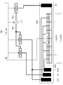
도 5에 도시한 바와 같이, 제어 회로(100)는 스위치(SW643), 스위치(SW653), 스위치(SW663)를 제어하기 위해서 스위치(SW643), 스위치(SW653), 스위치(SW663)에 각각 전기적으로 접속되어 있다.5, the
스위치(SW643)는 전원 접점(110a)과 전기접점(641)의 사이에 설치된 스위치(릴레이)이다. 스위치(SW643)는 제어 회로(100)로부터의 지시에 따라, 전원 접점(110a)과 전기접점(641) 사이를 접속하거나 접속해제한다. 스위치(SW653)는 전원 접점(110b)과, 전기접점(651)의 사이에 설치된 스위치이다. 스위치(SW643)는 제어 회로(100)로부터의 지시에 따라, 전원 접점(110b)와 전기접점(651) 사이를 접속하거나 접속해제한다. 스위치(SW663)는 전원 접점(110b)과, 전기접점(661)(661a, 661b)의 사이에 설치된 스위치이다. 스위치(SW663)는 제어 회로(100)로부터의 지시에 따라, 전원 접점(110b)과 전기접점(661)(661a, 661b) 사이를 접속하거나 접속해제한다.The switch SW643 is a switch (relay) provided between the
제어 회로(100)가 작업의 실행 지시를 수신할 때, 제어 회로(100)는 정착 처리에 사용되는 시트 P의 폭 사이즈 정보를 취득한다. 시트 P의 폭 사이즈 정보에 따라서, 스위치(SW643), 스위치(SW653), 스위치(SW663)의 온/오프 조합이 제어되어 발열체(620)의 발열 폭이, 시트 P를 가열 처리하기에 적합한 발열 폭이 되게 한다. 이때, 제어 회로(100), 전원(110), 스위치(SW643), 스위치(SW653), 스위치(SW663) 및 커넥터(700)는 히터(600)에 급전하는 급전부로서 기능한다.When the
시트 P가 대사이즈(장치에 사용가능한 최대 사이즈)인 경우, 즉, A3 사이즈 시트가 길이방향으로 급송되거나 A4 사이즈가 가로배향 형태로 급송되는 경우, 시트 P의 폭 사이즈는 약 297mm이 된다. 그로 인해, 제어 회로(100)는 발열체(620)의 발열 폭 B(도 5)를 제공하도록 급전을 제어한다. 이를 위해, 제어 회로(100)는 스위치(SW643), 스위치(SW653) 및 스위치(SW663) 모두를 온 상태가 되게 한다. 그 결과, 히터(600)에는 전기접점(641, 661a, 661b, 651)을 통해 전력이 공급되고, 발열체(620)의 12개 소구간 모두가 발열한다. 이때, 히터(600)는 약 297mm의 시트 P에 맞도록 약 320mm의 영역에 걸쳐 균일하게 발열한다.If the sheet P is a large size (maximum size that can be used in the apparatus), that is, if the A3 size sheet is fed in the longitudinal direction or the A4 size is fed in the transverse orientation form, the width size of the sheet P becomes about 297 mm. Thereby, the
시트 P의 사이즈가 소사이즈(최대 폭보다 좁음)인 경우, 즉, A4 사이즈 시트가 길이방향으로 급송되거나 A5 사이즈 시트가 가로배향 형태로 급송되는 경우, 시트 P의 폭은 약 210mm이 된다. 따라서, 제어 회로(100)는 발열체(620)의 발열 폭 A(도 5)를 제공한다. 따라서, 제어 회로(100)는 스위치(SW643), 스위치(SW653)를 온 상태로 하고, 스위치(SW663)를 오프 상태로 한다. 그 결과, 히터(600)에는 전기접점(641, 651)을 통해 급전이 행하여져, 발열체(620)의 12개의 소 구간 중 8개의 소 구간이 발열한다. 이때, 히터(600)는 약 210mm의 시트 P에 맞도록 약 213mm영역에 걸쳐 균일하게 발열한다.When the size of the sheet P is small (narrower than the maximum width), that is, when the A4 size sheet is fed in the longitudinal direction or the A5 size sheet is fed in the transverse orientation form, the width of the sheet P becomes about 210 mm. Thus, the
[전기 접점의 배치][Arrangement of electrical contacts]
전기접점의 배치 또는 배열을 설명한다. 도 8은 본 실시예에서의 전기접점의 배치도이다. 본 실시예에서, 전원 접점(110a)에 접속되는 공통 배선(640)이 기판의 일단부측(610d)에 배치되고, 전원 접점(110b)에 접속되는 대향 배선(650, 660a, 660b)이 기판의 폭 방향으로 기판의 타단부측(610b)에 배치되어 있다. 이러한 배치에 의해, 배선간의 단락이 방지된다. 본 실시예에서, 전원 접점(110a)에 접속되는 전기접점이 기판의 일단부측(610a)에 배치되고, 전원 접점(110b)에 접속되는 전기접점이 기판의 길이방향으로 기판의 일단부측(610b)에 배치되어 있다. 구체적으로, 기판의 일단부측(610a)에 전기접점(641)이 배치되고, 기판의 일단부측에 전기접점(651, 661a, 661b)이 배치된다. 이와 같은 구성으로 함으로써, 다른 전원 접점에 접속되는 전기접점간에 충분한 절연 거리가 보증된다. 동일한 전원 접점 측에 접속되는 전기접점간의 간격을 감소시킴으로써, 전기접점을 기판의 길이 방향으로 배열하는 것에 의한 기판의 길이 증가를 억제하고 있다. 나아가, 다른 전원 접점에 접속되는 전기접점을, 기판의 길이 방향 각 단부에 나누어서 배치함으로써, 전압 강하에 기인한 발열체의 발열 불균일성이 억제될 수 있다. 도면을 사용해서 상세하게 설명한다.The arrangement or arrangement of the electrical contacts will be described. 8 is a layout diagram of electrical contacts in this embodiment. In this embodiment, the
본 실시예에서는 상술한 바와 같이, 기판의 일단부측(610a)에 전기접점(641)이 설치되고, 기판의 타단부측(610b)에 전기접점(651, 661a, 661b)이 설치된다. 각 전기접점은 각 콘택트 단자로부터의 급전을 확실하게 받을 수 있도록, 2.5mm x 2.5mm 이상(기판의 폭 방향 및 길이 방향)의 크기를 가지며, 그 면적이 넓은 것이 바람직하다. 본 실시예에서, 전기접점(641)의 치수는 약 7mm x 약 3mm이며, 전기접점(661a)의 치수는 약 7mm x 약 3mm이며, 전기접점(661b)의 치수는 약 5mm x 약 3mm이며, 전기접점(651)의 치수는 약 6mm x 약 3mm이다.In this embodiment, as described above, the
상술한 바와 같이, 전기접점(641, 651, 661a, 661b)이 설치된 기판(610)의 부분은 절연 코트층을 갖지 않는다. 즉, 전기접점은 노출되어 있고, 전기 누설 및/또는 단락이 발생할 우려가 있다. 다른 전원 접점에 접속되는 전기접점간에 연면방전(creepage discharge)에 의한 단락이 발생하기 쉽다. 따라서, 다른 전원 접점에 접속되는 전기접점간에는 절연을 위한 충분한 간격(절연 거리)을 제공하는 것이 바람직하다. 그런데, 절연 거리를 크게 하면 기판(610) 사이즈가 증가되게 된다. 따라서, 기판(610)의 길이를 증가시키지 않도록 전기접점의 배치가 고려되는 것이 바람직하다.As described above, the portion of the
본 실시예의 정착장치(40)에서는, 전원 접점(110a)에 접속되는 전기접점과 전원 접점(110b)에 접속되는 전기접점이 미리 정해져 있다. 상세하게는, 전기접점(641a)은 전원 접점(110a)에 접속되고, 전기접점(651, 661a, 661b)은 전원 접점(110b)에 접속된다. 즉, 전기접점(641)과 전기접점(651, 661a, 661b)은 다른 전원 접점(대향 극성)에 접속되고, 따라서, 그 사이에 큰 전위차가 발생해서 연면방전에 의한 단락을 발생하기 쉽다. 이러한 환경에서, 본 실시예에서는, 기판의 일단부측(610a)에 전기접점(641)을 배치하고, 기판의 타단부측(610b)에 전기접점(651, 661a, 661b)을 배치함으로써, 전기접점(641)과 전기접점(651, 661a, 661b)의 사이에 충분한 절연 거리가 제공된다.In the fixing
서로 인접하게 배치된 기판의 타단부측(610b)에 배치된 전기접점(651, 661a, 661b)은 같은 전원 접점에 접속된다. 그로 인해, 이들 전기접점간에서는 큰 전위차가 발생하지 않는다. 즉, 전기접점(651과 661b) 사이의 간극 A와 전기접점(651과 661a) 사이의 간극 B는 연면방전에 의한 단락을 효과적으로 방지하기에 충분하다. 따라서, 간극 A 및 간극 B에는, 히터(600)가 정상 동작하기 위한 기능 절연이 제공된다면 충분하며, 이들은 최소화될 수 있다. 그러나, 커넥터(700b)의 설치 오차 및/또는 기판(610)의 열팽창에 기인하여 발생할 수 있는 단락을 고려하여, 본 실시예에서 간극 A 및 간극 B는 약 1.5mm이다. 전기접점(651과 661b) 사이의 비평행성으로 인해 전기접점(651과 661b)의 간격이 일정하지 않은 경우, 간격의 최솟값이 간극 A로 간주된다. 전기접점(651과 661a) 사이의 비평행성으로 인해 전기접점(651과 661a)의 간격이 일정하지 않은 경우, 이 간격의 최소값은 간극 B로 간주된다.The
다른 전원 접점에 접속되는 전기접점이 이웃해서 배치될 경우를 고려한다. 일본 전기 기기 및 재료 안전 법(첨부 표의 부록표)는 선간전압이 50V 내지 150V 사이인 다른 극성의 다른 위치 또는 충전부에서, 요구 공간 거리(연면 거리)는 약 2.5mm이다. 본 실시예에서는, 커넥터(700)의 설치 오차 및/또는 기판(610)의 열팽창에 기인하는 단락을 고려하여, 간극 E는 약 4.0mm이다.Consider the case where electrical contacts connected to different power contacts are placed next to each other. The Japanese Electrical Appliance and Material Safety Law (Appendix table in the attached table) shows that the required clearance distance (creepage distance) is about 2.5 mm at different polarity positions or live parts with line voltage between 50V and 150V. In the present embodiment, the gap E is about 4.0 mm in consideration of the installation error of the connector 700 and / or the short circuit due to the thermal expansion of the
다른 전원 접점에 접속되는 전기접점을 기판의 일단부측(610a)과 타단부측(610b)으로 분할함으로써, 인접하는 전기접점간의 간격을 감소시킬 수 있다. 상세하게는, 서로 인접하는 전기접점간의 간격이 4.0mm 미만(보다 바람직하게는 2.5mm 미만)으로 감소시킬 수 있다. 따라서, 전기접점을 길이 방향으로 배열하는 것에 의한 기판의 길이 방향으로의 기판의 확대를 억제할 수 있다.The interval between the adjacent electrical contacts can be reduced by dividing the electrical contact connected to the other power contact point into one
또한, 본 실시예와 같이, 단자 중 하나에 전기적으로 접속되는 전기접점(641)과, 다른 단자 측에 전기적으로 접속되는 전기접점(661a, 651, 661b)을 기판의 대향 단부 부분에 배치함으로써, 발열체의 길이 방향 온도 비균일성이 억제될 수 있다.By arranging the
기판의 길이 방향에서, 발열체(620d)는 발열체(620c)보다도 전기접점(641)로부터 먼 위치에 배치된다. 따라서, 전기접점(641)과 전극(642c) 사이에 작용하는 배선(640)의 경로 길이는, 전기접점(641)과 전극(642b) 사이를 접속하는 배선(640)의 경로 길이보다 길다. 한편, 전기접점(651)과 전극(652a)을 접속하는 배선(650)의 경로 길이는 전기접점(651)과 전극(652b)을 접속하는 배선(650)의 경로 길이보다 길다. 환언하면, 발열체(620d)와 전기접점을 접속하는 배선의 길이는 발열체(620c)와 전기접점을 접속하는 배선의 길이보다 길고, 발열체(620c)와 전기접점(651)을 접속하는 배선의 길이는 발열체(620d)와 전기접점(651)을 접속하는 배선의 길이보다 길다.In the longitudinal direction of the substrate, the
따라서, 배선의 저항에 의한 전압 강하가 기판의 길이방향 대향 단부들 사이에서 상쇄될 수 있다. 달리 말해서, 발열체(620d)와 발열체(620c)의 발열량에 편차가 발생하는 것을 억제할 수 있다. 동일한 바가 발열체(620d)와 발열체(620c) 이외의 다른 발열체에 대해서도 적용된다.Thus, the voltage drop due to the resistance of the wiring can be offset between the longitudinally opposite ends of the substrate. In other words, it is possible to suppress a deviation in the amount of heat generated between the
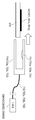
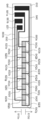
도 15는 비교예의 히터를 도시한다. 본 실시예에서, 전기접점(661a, 651, 661b)은 기판의 타단부측(610b)에 제공되지만, 비교예에서, 전기접점(661a, 651, 661b)은 기판의 일단부측(610a)에 제공된다. 즉, 비교예에서는, 모든 전기접점이 기판의 일단부 측에 제공된다. 비교예의 히터는 전기접점(661a, 651, 661b)의 위치와, 배선(660a, 650, 660b)의 경로이외의 구성은 본 실시예의 히터와 동일하다.Fig. 15 shows a heater of a comparative example. In the present embodiment, the
상술한 비교예의 히터와 본 실시예의 히터를 사용해서 발열체(620)의 발열 부분의 상태를 점검하기 위해 비교시험이 이루어졌다. 비교시험에서, 본 실시예의 히터 및 비교예의 히터 각각에서, 전기접점(641)과 전기접점(661a, 651, 661b)의 사이에 100V의 전압을 인가하고, 몇초 후의 발열부(620)의 온도 분포가 열 카메라에서 계측되었다. 도 16은 비교시험의 결과를 도시한다. 도 16의 그래프 횡축은 길이방향 중심 위치를 기준으로 한 길이방향의 발열체의 위치(mm)이다. 발열체의 일단부측을 마이너스, 발열체의 타단부측을 플러스로 나타낸다. 도 16의 그래프 종축은 발열체의 표면 온도(℃)이다.A comparative test was conducted to check the state of the heating portion of the
도 16에 도시한 바와 같이, 비교예에서는 발열체의 일단부의 온도가 약 230℃이고, 발열체의 타단부의 온도는 약 200℃이다. 즉, 비교예에서는 발열체의 길이 방향 양단에서 약 30℃의 온도 편차가 존재한다. 한편, 본 실시예의 경우에, 양 단부에서 발열체의 온도는 약 210℃이다. 즉, 본 실시예에서는 길이 방향에 걸친 온도 편차가 작다. 따라서, 비교예의 히터를 구비한 정착장치와 비교해서 본 실시예의 히터를 구비한 정착장치는, 정착 처리 시에 화상의 광택 비균일성이 발생하기 어렵고, 양호한 화상을 출력할 수 있다.As shown in Fig. 16, in the comparative example, the temperature of one end of the heating element is about 230 deg. C, and the temperature of the other end of the heating element is about 200 deg. That is, in the comparative example, there is a temperature deviation of about 30 占 폚 at both ends in the longitudinal direction of the heat generating element. On the other hand, in the case of this embodiment, the temperature of the heating element at both ends is about 210 占 폚. That is, in this embodiment, the temperature deviation across the longitudinal direction is small. Therefore, as compared with the fixing device having the heater of the comparative example, the fixing device provided with the heater of this embodiment hardly causes gloss unevenness of the image during the fixing process, and can output a good image.
[실시예 2][Example 2]
본 발명의 실시예 2에 따른 히터에 대해서 설명한다. 도 9는 본 실시예에서의 화상 가열 장치의 구성 관계의 예시도이다. 도 8은 본 실시예에서의 전기접점의 배치를 도시한다. 실시예 1에서는, 대향 배선(660a)에 접속되는 전기접점(661a)과, 대향 배선(660b)에 접속되는 전기접점(661b)이 별개로 제공된다. 본 실시예에서는, 대향 배선(660a)과 대향 배선(660b)에 접속되는 전기접점(661)이 설치된다. 즉, 본 실시예의 전기접점(661)은 실시예 1의 전기접점(661a, 661b)으로서 기능한다. 본 실시예의 이러한 구조에 의해, 기판의 길이가 감소된다. 도면을 사용해서 본 실시예의 히터(600)의 세부사항을 설명한다. 실시예 2의 정착장치(40)의 구성은 히터(600)에 관한 구성이외는 실시예 1의 것들과 기본적으로 동일하다. 본 실시예의 설명에서, 본 실시예의 대응하는 기능을 갖는 요소에 대해서는 실시예 1과 동일한 참조 번호가 부여되고 그 상세한 설명은 간결성을 위해 생략한다.A heater according to a second embodiment of the present invention will be described. Fig. 9 is an exemplary view showing a configuration relationship of the image heating apparatus in this embodiment. Fig. 8 shows the arrangement of the electrical contacts in this embodiment. In the first embodiment, the
도 9에 도시한 바와 같이, 본 실시예의 히터(600)의 발열체(620)는 기판의 일단부측(610a)에 제공된 전기접점(641)과, 기판의 타단부측(610b)에 제공된 전기접점(651, 661)으로부터 급전이 이루어진다. 기판의 이 타단부측(610b)에서, 전기접점(661)과 전기접점(651)은 기판(610)의 길이 방향으로 배열된다.9, the
본 실시예의 히터(600)에서, 대향 배선(660a 및 660b)이 전기접점(651)을 둘러싸도록 연장한다. 이와 같은 구성에 의해, 대향 배선(660a 및 660b)은 전기접점(661)에 접속된다. 전기접점(661)은 실시예 1에서의 전기접점(661a와 661b)으로서 기능한다.In the
본 실시예에서, 전기접점(661)의 치수는 약 7mm x 약 3mm이며, 전기접점(651)의 치수는 약 6mm x 약 3m m이다.In this embodiment, the dimension of the
서로 인접하게 배치된 기판의 타단부측(610b)에 배치된 전기접점(651, 661)은 같은 전원 접점에 접속된다. 따라서, 도 10에 도시하는 전기접점(651, 661)의 사이 간격 간극 C는 히터(600)의 정상 동작을 보증하기 위한 기능 절연이 제공되면 충분하고, 이들은 최소화될 수 있다. 그러나, 커넥터(700b)의 설치 오차 및/또는 기판(610)의 열팽창에 기인한 가능한 단락을 고려하여, 본 실시예의 간극 C는 약 1.5mm이다. 전기접점(651과 661b) 사이의 비평행성으로 인해 전기접점(651과 661b)의 간격이 일정하지 않으면, 간극의 최소값이 간극 C로 간주된다.The
다른 전원 접점에 접속되는 전기접점을 기판의 일단부측(610a)과 타단부측(610b)으로 분할함으로써, 전기접점간의 간격이 감소된다. 상세하게는, 서로 인접하는 전기접점간의 간격은 4.0mm 미만(보다 바람직하게는 2.5mm 미만)으로 감소될 수 있다. 따라서, 전기접점을 기판의 길이 방향으로 배열하는 것에 의한 기판의 길이 방향으로의 기판 확대를 억제할 수 있다. 본 실시예에서, 복수의 대향 배선(660a, 660b)이 단일 전기접점(661)에 접속되고, 따라서, 실시예 1과 비교해서 전기접점의 수가 더 작다. 따라서, 하나의 전기접점(약 3mm)과 하나의 간극(약 1.5mm)의 합에 대응하는 기판(610)의 길이가 감소될 수 있다.The interval between the electrical contacts is reduced by dividing the electrical contact connected to the other power contact into the one
[실시예 3][Example 3]
본 발명의 실시예 3의 히터에 대해서 설명한다. 도 11은 본 실시예에서의 화상 가열 장치의 구성 관계의 예시도이다. 도 12는 본 실시예의 전기접점의 배치도이다. 실시예 2에서, 전기접점(651과 661)은 기판의 길이 방향으로 기판의 타단부측(610b)에 배열하여 배치된다. 실시예 3에서는, 기판의 타단부측(610b)에서, 전기접점(651과 661)이 기판의 폭 방향으로 배열된다. 본 실시예의 이러한 구성에 의해, 기판의 길이가 감소된다. 도면을 사용해서 본 실시예의 히터(600)의 세부사항을 설명한다. 실시예 3의 정착장치(40)의 구성은 히터(600)에 관한 구성 이외는 실시예 2의 것들과 기본적으로 동일하다. 따라서, 본 실시예의 대응 기능을 갖는 요소에는 실시예 2와 동일한 참조 번호를 부여하고, 간결성을 위해 그 상세한 설명을 생략한다.A heater according to a third embodiment of the present invention will be described. Fig. 11 is an exemplary diagram showing a configuration relationship of the image heating apparatus in this embodiment. Fig. 12 is a layout diagram of the electrical contact of this embodiment. In
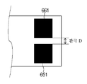
도 11에 도시한 바와 같이, 본 실시예의 히터(600)에서, 발열체(620)는 기판(610)의 길이 방향 일단부측(610a)에 제공된 전기접점(641, 651, 661)으로부터 급전이 이루어진다. 전기접점(661)은 사이에 간격을 두고 전기접점(641)에 인접하게 배치되며, 이들은 기판(610)의 길이 방향으로 배열된다. 전기접점(651)은 사이에 간격을 두고 전기접점(641)에 인접하게 배치되며, 이들은 기판(610)의 길이 방향으로 배치된다. 전기접점(661)은 사이에 간격을 두고 전기접점(651)에 인접하게 배치되며, 이들은 기판의 폭 방향으로 배치된다.11, in the
본 실시예의 히터(600)에서는, 대향 배선(660a 및 660b)이 전기접점(651)을 둘러싸도록 연장한다. 이와 같은 구성에 의해, 대향 배선(660a 및 660b)은 전기접점(661)에 접속된다. 전기접점(661)은 실시예 1의 전기접점(661a와 661b)으로서 기능한다.In the
본 실시예에서, 전기접점(661)의 치수는 약 7mm x 약 3mm이며, 전기접점의 치수는 약 6mm x 약 3mm이다.In this embodiment, the dimension of the
서로 인접하게 배치된 기판의 타단부측(610b)에 배치되어 있는 전기접점(651, 661)은 같은 전원 접점에 접속된다. 따라서, 도 12에 나타내는 전기접점(651, 661)의 사이의 간극 D는 히터(600)의 정상 동작을 보증하기 위한 기능 절연이 제공되는 것으로 족하며, 이들은 최소화될 수 있다. 그러나, 커넥터(700b)의 설치 오차 및/또는 기판(610)의 열팽창에 기인하는 가능한 단락을 고려하여, 본 실시예에서는 간극 D는 약 1.5mm이다. 전기접점(651과 661) 사이의 비평행성으로 인해 전기접점(651과 661b)의 간격이 일정하지 않으면, 간격의 최소값이 간극 D로 간주된다. 이렇게 구성함으로써, 전기접점의 폭이 감소될 수 있다. 본 실시예에서, 기판의 타단부측(610b)에서 전체 전기접점의 폭은 약 7.5mm이고, 약 8 mm의 폭을 갖는 기판(610)에 전기 접점이 수용될 수 있다.The
다른 전원 접점 측에 접속되는 전기접점을 기판의 일단부측(610a)과 타단부측(610b)으로 분할함으로써, 인접하는 전기접점간의 간격이 감소될 수 있다. 상세하게는, 서로 인접하는 전기접점간의 간격을 4.0mm 미만(보다 바람직하게는 2.5mm 미만)으로 감소시킬 수 있다. 따라서, 전기접점간의 간격을 감소시킴으로써, 2개의 전기접점이 폭방향으로 배열될 수 있다. 달리 말해서, 본 실시예에서는 실시예 2와 비교해서 기판(610)의 길이 방향으로 배열된 전기접점의 수가 1개 감소된다. 따라서, 기판(610)의 길이가 하나의 전기 접점(약 3mm)과 하나의 간극(약 1.5mm)의 합에 대응하여 감소될 수 있다.The interval between adjacent electrical contacts can be reduced by dividing the electrical contact connected to the other power contact side into one
상술한 실시예의 히터 자체는 다음과 같이 요약된다.The heater itself of the above-described embodiment is summarized as follows.
A. 세장형 기판; 상기 기판의 길이방향 일 단부에 인접하게 상기 기판 상에 제공된 제1 전극; 상기 기판의 길이방향 타단부에 인접하게 상기 기판 상에 제공되고, 상기 제1 전극으로부터 전기적으로 격리된 제2 전극; 상기 기판의 상기 길이방향 타단부에 인접하게 상기 기판 상에 제공되고, 상기 제1 전극 및 상기 제2 전극으로부터 전기적으로 격리된 제3 전극; 상기 기판 상에 제공되고 상기 제1 전극과 전기적으로 접속되는 제1 공통 배선; 상기 기판 상에 제공되고 상기 제2 전극과 전기적으로 접속되는 제2 공통 배선; 상기 기판 상에 제공되고 상기 제3 전극과 전기적으로 접속되는 제3 공통 배선; 상기 기판 상에 제공되고, 상기 제1 전극과 전기적으로 접속되는 제1 군의 전기접점; 상기 기판 상에 제공되는 제2 군의 전기접점으로서, 상기 제1 및 제2 군의 전기접점은 교번 배열식으로 상기 기판의 길이 방향을 따라 배열되고, 상기 전기접점의 제2 군은 전기접점의 제1 하위군 및 전기접점의 제2 하위군을 포함하고, 상기 제1 하위군의 전기접점은 상기 제2 공통 배선과 전기적으로 접속되고, 상기 제2 하위군의 전기접점은 상기 제3 공통 배선과 전기적으로 접속되는, 제2 군의 전기접점; 및 상기 제1 전극과 상기 제2 전극의 사이에서 상기 기판의 표면 상에 제공되는 세장형 통전가능 히터부로서, 상기 기판에 근접한 상기 히터부의 표면에서 상기 제1 및 제2 군의 전기접점과 전기적으로 접속되는, 세장형 통전가능 히터부를 포함하는 히터.A. elongated substrate; A first electrode provided on the substrate adjacent to one longitudinal end of the substrate; A second electrode provided on the substrate adjacent to the other longitudinal end of the substrate, the second electrode being electrically isolated from the first electrode; A third electrode provided on the substrate adjacent to the other longitudinal end of the substrate, the third electrode being electrically isolated from the first electrode and the second electrode; A first common wiring provided on the substrate and electrically connected to the first electrode; A second common wiring provided on the substrate and electrically connected to the second electrode; A third common wiring provided on the substrate and electrically connected to the third electrode; A first group of electrical contacts provided on the substrate and electrically connected to the first electrode; A second group of electrical contacts provided on the substrate, wherein the first and second groups of electrical contacts are arranged in an alternating arrangement along the longitudinal direction of the substrate, and the second group of electrical contacts The first subgroup and the second subgroup of the electrical contacts, wherein the electrical contacts of the first subgroup are electrically connected to the second common wiring, and the electrical contacts of the second subgroup are electrically connected to the third common wiring A second group of electrical contacts electrically connected to the first group of contacts; And an elongated electrically conductive heater portion provided on the surface of the substrate between the first electrode and the second electrode, wherein the elongate electrically conductive heater portion is electrically connected to the first and second groups of electrical contacts at the surface of the heater portion, And a heater for heating the heater.
B. 세장형 기판; 상기 기판의 길이방향 일 단부에 인접하게 상기 기판 상에 제공된 제1 전극; 상기 기판의 길이방향 타단부에 인접하게 상기 기판 상에 제공되고, 상기 제1 전극으로부터 전기적으로 격리된 제2 전극; 상기 기판의 상기 길이방향 타단부에 인접하게 상기 기판 상에 제공되고, 상기 제1 전극 및 상기 제2 전극으로부터 전기적으로 격리된 제3 전극; 상기 기판 상에 제공되고 상기 제1 전극과 전기적으로 접속되는 제1 공통 배선; 상기 기판 상에 제공되고 상기 제2 전극과 전기적으로 접속되는 제2 공통 배선; 상기 기판 상에 제공되고 상기 제3 전극과 전기적으로 접속되는 제3 공통 배선; 상기 기판 상에 제공되고, 상기 제1 전극과 전기적으로 접속되는 제1 군의 전기접점; 상기 기판 상에 제공되는 제2 군의 전기접점으로서, 상기 제1 및 제2 군의 전기접점은 교번 배열식으로 상기 기판의 길이 방향을 따라 배열되고, 상기 전기접점의 제2 군은 전기접점의 제1 하위군 및 전기접점의 제2 하위군을 포함하고, 상기 제1 하위군의 전기접점은 상기 제2 공통 배선과 전기적으로 접속되고, 상기 제2 하위군의 전기접점은 상기 제3 공통 배선과 전기적으로 접속되는, 제2 군의 전기접점; 및 상기 제1 전극과 상기 제2 전극의 사이에서 상기 기판의 표면 상에 제공되는 세장형 통전가능 히터부로서, 상기 기판으로부터 이격된 상기 히터부의 표면에서 상기 제1 및 제2 군의 전기접점과 전기적으로 접속되는, 세장형 통전가능 히터부를 포함하는 히터. B. elongated substrate; A first electrode provided on the substrate adjacent to one longitudinal end of the substrate; A second electrode provided on the substrate adjacent to the other longitudinal end of the substrate, the second electrode being electrically isolated from the first electrode; A third electrode provided on the substrate adjacent to the other longitudinal end of the substrate, the third electrode being electrically isolated from the first electrode and the second electrode; A first common wiring provided on the substrate and electrically connected to the first electrode; A second common wiring provided on the substrate and electrically connected to the second electrode; A third common wiring provided on the substrate and electrically connected to the third electrode; A first group of electrical contacts provided on the substrate and electrically connected to the first electrode; A second group of electrical contacts provided on the substrate, wherein the first and second groups of electrical contacts are arranged in an alternating arrangement along the longitudinal direction of the substrate, and the second group of electrical contacts The first subgroup and the second subgroup of the electrical contacts, wherein the electrical contacts of the first subgroup are electrically connected to the second common wiring, and the electrical contacts of the second subgroup are electrically connected to the third common wiring A second group of electrical contacts electrically connected to the first group of contacts; And an elongated electrically conductive heater portion provided on the surface of the substrate between the first electrode and the second electrode, wherein the elongate electrically conductive heater portion is disposed between the first and second groups of electrical contacts at the surface of the heater portion, A heater comprising a elongated electrically conductive heater portion electrically connected.
C. 세장형 기판; 상기 기판의 길이방향 일 단부에 인접하게 상기 기판 상에 제공된 제1 전극; 상기 기판의 길이방향 타단부에 인접하게 상기 기판 상에 제공되고, 상기 제1 전극으로부터 전기적으로 격리된 제2 전극; 상기 기판의 상기 길이방향 타단부에 인접하게 상기 기판 상에 제공되고, 상기 제1 전극 및 상기 제2 전극으로부터 전기적으로 격리된 제3 전극; 상기 기판 상에 제공되고 상기 제1 전극과 전기적으로 접속되는 제1 공통 배선; 상기 기판 상에 제공되고 상기 제2 전극과 전기적으로 접속되는 제2 공통 배선; 상기 기판 상에 제공되고 상기 제3 전극과 전기적으로 접속되는 제3 공통 배선; 상기 기판 상에 제공되고, 상기 제1 전극과 전기적으로 접속되는 제1 군의 전기접점; 상기 기판 상에 제공되는 제2 군의 전기접점으로서, 상기 제1 및 제2 군의 전기접점은 교번 배열식으로 상기 기판의 길이 방향을 따라 배열되고, 상기 전기접점의 제2 군은 전기접점의 제1 하위군 및 전기접점의 제2 하위군을 포함하고, 상기 제1 하위군의 전기접점은 상기 제2 공통 배선과 전기적으로 접속되고, 상기 제2 하위군의 전기접점은 상기 제3 공통 배선과 전기적으로 접속되는, 제2 군의 전기접점; 및 상기 제1 전극과 상기 제2 전극의 사이에서 상기 기판의 표면 상에 제공되는 세장형 통전가능 히터부로서, 서로 전기적으로 격리된 부분들을 포함하고, 상기 부분들은 상기 기판에 근접한 상기 히터부의 표면에서 상기 제1 및 제2 군의 전기접점 중 인접한 전기 접점들 사이에 제공되어 접촉되는, 히터부를 포함하는 히터. C. elongated substrate; A first electrode provided on the substrate adjacent to one longitudinal end of the substrate; A second electrode provided on the substrate adjacent to the other longitudinal end of the substrate, the second electrode being electrically isolated from the first electrode; A third electrode provided on the substrate adjacent to the other longitudinal end of the substrate, the third electrode being electrically isolated from the first electrode and the second electrode; A first common wiring provided on the substrate and electrically connected to the first electrode; A second common wiring provided on the substrate and electrically connected to the second electrode; A third common wiring provided on the substrate and electrically connected to the third electrode; A first group of electrical contacts provided on the substrate and electrically connected to the first electrode; A second group of electrical contacts provided on the substrate, wherein the first and second groups of electrical contacts are arranged in an alternating arrangement along the longitudinal direction of the substrate, and the second group of electrical contacts The first subgroup and the second subgroup of the electrical contacts, wherein the electrical contacts of the first subgroup are electrically connected to the second common wiring, and the electrical contacts of the second subgroup are electrically connected to the third common wiring A second group of electrical contacts electrically connected to the first group of contacts; And a elongate electrically conductive heater portion provided on the surface of the substrate between the first electrode and the second electrode, the electrically conductive heater portion including electrically isolated portions of the heater portion, Wherein the first and second groups of electrical contacts are provided between adjacent ones of the first and second groups of electrical contacts.
D. 세장형 기판; 상기 기판의 길이방향 일 단부에 인접하게 상기 기판 상에 제공된 제1 전극; 상기 기판의 길이방향 타단부에 인접하게 상기 기판 상에 제공되고, 상기 제1 전극으로부터 전기적으로 격리된 제2 전극; 상기 기판의 상기 길이방향 타단부에 인접하게 상기 기판 상에 제공되고, 상기 제1 전극 및 상기 제2 전극으로부터 전기적으로 격리된 제3 전극; 상기 기판 상에 제공되고 상기 제1 전극과 전기적으로 접속되는 제1 공통 배선; 상기 기판 상에 제공되고 상기 제2 전극과 전기적으로 접속되는 제2 공통 배선; 상기 기판 상에 제공되고 상기 제3 전극과 전기적으로 접속되는 제3 공통 배선; 상기 기판 상에 제공되고, 상기 제1 전극과 전기적으로 접속되는 제1 군의 전기접점; 상기 기판 상에 제공되는 제2 군의 전기접점으로서, 상기 제1 및 제2 군의 전기접점은 교번 배열식으로 상기 기판의 길이 방향을 따라 배열되고, 상기 전기접점의 제2 군은 전기접점의 제1 하위군 및 전기접점의 제2 하위군을 포함하고, 상기 제1 하위군의 전기접점은 상기 제2 공통 배선과 전기적으로 접속되고, 상기 제2 하위군의 전기접점은 상기 제3 공통 배선과 전기적으로 접속되는, 제2 군의 전기접점; 및 상기 제1 전극과 상기 제2 전극의 사이에서 상기 기판의 표면 상에 제공되는 세장형 통전가능 히터부로서, 서로 전기적으로 격리된 부분들을 포함하고, 상기 부분들은 상기 기판으로부터 이격된 상기 히터부의 표면에서 상기 제1 및 제2 군의 전기접점 중 인접한 전기 접점들 사이에 제공되어 접촉되는, 히터부를 포함하는 히터. D. elongated substrate; A first electrode provided on the substrate adjacent to one longitudinal end of the substrate; A second electrode provided on the substrate adjacent to the other longitudinal end of the substrate, the second electrode being electrically isolated from the first electrode; A third electrode provided on the substrate adjacent to the other longitudinal end of the substrate, the third electrode being electrically isolated from the first electrode and the second electrode; A first common wiring provided on the substrate and electrically connected to the first electrode; A second common wiring provided on the substrate and electrically connected to the second electrode; A third common wiring provided on the substrate and electrically connected to the third electrode; A first group of electrical contacts provided on the substrate and electrically connected to the first electrode; A second group of electrical contacts provided on the substrate, wherein the first and second groups of electrical contacts are arranged in an alternating arrangement along the longitudinal direction of the substrate, and the second group of electrical contacts The first subgroup and the second subgroup of the electrical contacts, wherein the electrical contacts of the first subgroup are electrically connected to the second common wiring, and the electrical contacts of the second subgroup are electrically connected to the third common wiring A second group of electrical contacts electrically connected to the first group of contacts; And a elongate electrically conductive heater portion provided on the surface of the substrate between the first electrode and the second electrode, the elongate electrically conductive heater portion comprising electrically isolated portions of the heater portion, And a heater portion provided on and adjacent to said first and second groups of electrical contacts at a surface thereof between adjacent ones of said electrical contacts.
(다른 실시예)(Another embodiment)
본 발명은 상술한 실시예의 특정 치수에 한정되지 않는다. 치수들은 상황에 따라 본 기술의 숙련자에 의해 적절히 변경될 수 있다. 실시예는 본 발명의 개념에서 변형될 수 있다.The present invention is not limited to the specific dimensions of the embodiments described above. Dimensions may be suitably modified by one skilled in the art depending on the situation. Embodiments may be modified in the context of the present invention.
히터(600)의 발열 영역은 시트가 그 중심이 정착 장치의 중심과 정렬된 상태로 공급되는 것에 기초한 상술한 예에 한정되지 않는다. 대안적으로, 히터(600)의 발열 영역은 시트가 그 일 단부가 정착 장치의 단부와 정렬된 상태로 공급되는 경우에 맞도록 변경될 수 있다. 구체적으로, 발열 영역 A에 대응하는 발열체가 발열체(620c 내지 620j)가 아니고, 발열체(620a 내지 620e)이어도 된다. 이러한 배열에서, 발열 영역이 소사이즈 시트를 위한 것으로부터 대사이즈 시트를 위한 것으로 전환될 때, 발열 영역은 대향 단부 양자 모두에서 확장되지 않는다. 일 단부측의 발열 영역이 확장될 수 있다.The heat generating region of the
히터(600)의 발열 영역의 패턴의 수는 2개에 한정되지 않는다. 예로서, 3개 이상의 패턴이 제공될 수 있다.The number of patterns in the heating region of the
전기접점의 수는 3개 또는 4개로 한정되지 않는다. 전원 접점(110a)에 접속된 전기 접점이 기판의 일 단부측(610a)에 배치되고 전원 접점(110b)에 접속된 전기접점이 기판의 타단부측(610b)에 배치되는 경우 5개 이상의 전기 접점이 제공될 수 있다. 예로서, 실시예 1에서, 기판의 일 단부측(610a)에서, 전원 접점(110a)에 접속되고 전기접점(641)과는 다른 전기 접점이 제공될 수 있다. 유사하게, 실시예 1에서, 기판의 타단부측(610b)에서, 전원 접점(110b)에 접속되고 전기접점(651, 661a, 661b)과는 다른 전기접점이 제공될 수 있다.The number of electrical contacts is not limited to three or four. When the electrical contact connected to the
발열 요소(620)의 형성 방법은 실시예 1 및 2에 개시된 것들에 한정되지 않는다. 실시예 1에서, 기판(610)의 길이 방향으로 연장하는 발열체(620) 상에 공통 전극(642)과 대향 전극(652, 662)이 적층된다. 그러나, 기판(610)의 길이 방향으로 연장하는 형태로 전극이 형성되고, 인접하는 전극간에 발열체(620a 내지 620l)가 형성될 수 있다.The method of forming the
벨트(603)는 히터(600)에 의해 그 내면에서 지지되고, 롤러(70)에 의해 구동되는 구성에 한정되지 않는다. 예를 들어, 복수의 롤러에 둘레로 벨트가 연장하고 복수의 롤러 중 어느 하나에 의해 구동되는 소위 벨트 유닛 형태일 수 있다. 그러나, 저 열용량화의 관점에서 실시예 1 내지 4와 같은 구성이 바람직하다.The
벨트(603)와 협력하여 닙부 N을 형성하는 부재는 롤러(70) 같은 롤러 부재에 한정되지 않는다. 예를 들어, 이는 복수의 롤러 둘레로 연장되는 벨트를 포함하는 소위 가압 벨트 유닛일 수 있다.The member that forms the nip N in cooperation with the
프린터(1)인 화상 형성 장치는 풀컬러를 형성할 수 있는 화상 형성 장치에 한정되지 않고, 모노크롬의 화상을 형성하는 화상 형성 장치일 수 있다. 화상 형성 장치는 예로서, 복사기, FAX 및 이들 기능을 구비한 복합기 등일 수 있다.The image forming apparatus which is the
화상 가열 장치는 시트 P 상에 토너 화상을 정착하기 위한 장치에 한정되지 않는다. 이는 반 정착 토너 화상을 완전 정착 화상으로 정착하기 위한 장치나 이미 정착된 화상을 가열하기 위한 장치일 수 있다. 화상 가열 장치로서의 정착장치(40)는 예를 들어 화상의 광택이나 표면 특성을 조절하는 표면가열 장치일 수 있다.The image heating apparatus is not limited to the apparatus for fixing the toner image on the sheet P. This may be an apparatus for fixing the semi-fixed toner image as a completely fixed image or an apparatus for heating an already fixed image. The fixing
본 발명을 예시적 실시예를 참조로 설명하였지만, 본 발명은 개시된 예시적 실시예에 한정되지 않는다는 것을 이해하여야 한다. 이하의 청구범위의 범주는 모든 변형 및 균등 구조와 기능을 포함하는 가장 광범위한 해석에 준하여야 한다.While the present invention has been described with reference to exemplary embodiments, it is to be understood that the invention is not limited to the disclosed exemplary embodiments. The scope of the following claims is to be accorded the broadest interpretation, including all modifications and equivalent structures and functions.
Claims (26)
상기 히터는 상기 벨트를 가열하기 위해 상기 벨트와 접촉가능하고,
상기 히터는,
기판,
상기 기판 상에 제공되어 제1 단자와 전기적으로 접속될 수 있는 적어도 하나의 제1 접점부 및 상기 기판 상에 제공되어 제2 단자와 전기적으로 접속될 수 있는 복수의 제2 접점부를 포함하는 복수의 접점부,
미리 정해진 간격을 두고 상기 기판의 길이 방향으로 배열된 복수의 전극부,
상기 제1 접점부와 전기적으로 접속된 상기 전극부 및 상기 제2 접점부와 전기적으로 접속된 상기 전극부가 상기 기판의 길이 방향으로 교대로 배열되도록 상기 접점부 중 각각의 접점부와 상기 전극부를 전기적으로 접속하는 복수의 배선부, 및
인접한 전극부 사이의 급전에 의해 발열하도록 인접한 전극부 사이에 각각 제공되는 복수의 발열부
를 포함하고,
상기 제1 접점부 모두는 길이방향으로 상기 기판이 일 단부측에 제공되고, 상기 제2 접점부 모두는 길이방향으로 상기 기판의 타단부측에 제공되는 히터.A heater which can be used in combination with an image heating device including a feeder portion having a first terminal and a second terminal, and an endless belt for heating an image on a sheet,
The heater being capable of contacting the belt to heat the belt,
The heater
Board,
A plurality of first contact portions provided on the substrate and capable of being electrically connected to the first terminals and a plurality of second contact portions provided on the substrate and capable of being electrically connected to the second terminals, The contact portion,
A plurality of electrode portions arranged in the longitudinal direction of the substrate at predetermined intervals,
The electrode portions electrically connected to the first contact portions and the electrode portions electrically connected to the second contact portions are alternately arranged in the longitudinal direction of the substrate so that the respective contact portions and the electrode portions of the contact portions are electrically A plurality of wiring portions connected to each other through
And a plurality of heating portions provided between adjacent electrode portions to generate heat by the power supply between the adjacent electrode portions,
Lt; / RTI >
Wherein all of the first contact portions are provided on one end side in the longitudinal direction and all of the second contact portions are provided on the other end side of the substrate in the longitudinal direction.
상기 발열부의 제1 발열부를 상기 제1 접점부와 전기적으로 접속하는 제1 배선부,
상기 제1 발열부와는 다른 상기 발열부의 제2 발열부를 상기 제2 접점부와 전기적으로 연결하는 제2 배선부,
상기 제1 발열부를 상기 제2 접점부 중 미리 정해진 접점부와 전기적으로 접속하는 제3 배선부,
상기 제2 발열부를 미리 정해진 접점부와 전기적으로 접속하는 제4 배선부를 포함하고,
상기 제1 배선부는 상기 제2 배선부보다 길고, 상기 제4 배선부는 상기 제3 배선부보다 긴 히터.The semiconductor device according to claim 1,
A first wiring portion for electrically connecting the first heat generating portion of the heat generating portion to the first contact portion,
A second wiring portion for electrically connecting the second heat generating portion of the heat generating portion, which is different from the first heat generating portion, to the second contact portion,
A third wiring portion electrically connecting the first heat generating portion to a predetermined contact portion of the second contact portion,
And a fourth wiring portion for electrically connecting the second heat generating portion to a predetermined contact portion,
The first wiring portion is longer than the second wiring portion, and the fourth wiring portion is longer than the third wiring portion.
상기 제2 접점부는 상기 제1 발열부와 전기적으로 접속되는 제1 접점부 및 상기 제2 발열부 및 상기 제3 발열부와 전기적으로 접속되는 제2 접점부를 포함하는 히터.The heat generating apparatus according to claim 1, wherein the heat generating portion includes a first heat generating portion, a second heat generating portion disposed closer to one longitudinal end portion of the heater than the first heat generating portion, And a third heat generating portion disposed closer to the end portion,
Wherein the second contact portion includes a first contact portion electrically connected to the first heat generating portion and a second contact portion electrically connected to the second heat generating portion and the third heat generating portion.
제1 단자 및 제2 단자를 구비하는 급전부,
시트 상의 화상을 가열하기 위한 엔드리스 벨트,
상기 벨트 내측에 제공되고 상기 벨트의 폭 방향으로 연장하는 기판,
상기 기판 상에 제공되어 제1 단자와 전기적으로 접속될 수 있는 적어도 하나의 제1 접점부와, 상기 기판 상에 제공되어 제2 단자와 전기적으로 접속될 수 있는 복수의 제2 접점부를 포함하는 복수의 접점부,
미리 정해진 간격을 두고 상기 기판의 길이 방향으로 배열된 복수의 전극부,
상기 제1 접점부에 전기적으로 접속된 상기 전극부 및 상기 제2 접점부와 전기적으로 접속된 상기 전극부가 상기 기판의 길이방향으로 교대로 배열되도록 상기 접점부 중 각각의 접점부와 상기 전극부를 전기적으로 접속하는 복수의 배선부, 및
인접한 전극부 사이의 급전에 의해 발열하도록 인접한 전극부 각각의 사이에 제공된 복수의 발열부
를 포함하고,
상기 장치와 함께 사용할 수 있는 최대 폭을 갖는 시트가 가열될 때, 상기 급전부는 상기 제1 접점부와 모든 상기 제2 접점부를 통해 상기 발열부 모두에 급전하여 상기 발열부 모두가 발열하게 하고, 상기 최대 폭보다 작은 폭을 갖는 시트가 가열될 때, 상기 급전부는 상기 제1 접점부와 일부 상기 제2 접점부를 통해 상기 제1 발열부와 일부 상기 제2 발열부에 급전하여 상기 발열부 중 일부가 발열하게 하며,
상기 제1 접점부 모두는 길이방향으로 상기 기판의 일 단부측에 제공되고, 상기 제2 접점부 모두는 길이 방향으로 상기 기판의 타단부측에 제공되는 화상 가열 장치.An image heating apparatus comprising:
A power feeder having a first terminal and a second terminal,
An endless belt for heating an image on a sheet,
A substrate provided inside the belt and extending in a width direction of the belt,
At least one first contact portion provided on the substrate and capable of being electrically connected to the first terminal and a plurality of second contact portions provided on the substrate and capable of being electrically connected to the second terminal, The contact portion,
A plurality of electrode portions arranged in the longitudinal direction of the substrate at predetermined intervals,
The electrode portions electrically connected to the first contact portions and the electrode portions electrically connected to the second contact portions are alternately arranged in the longitudinal direction of the substrate so that the respective contact portions and the electrode portions of the contact portions are electrically A plurality of wiring portions connected to each other through
A plurality of heating portions provided between adjacent electrode portions so as to generate heat by power supply between adjacent electrode portions,
Lt; / RTI >
When the sheet having the maximum width that can be used together with the apparatus is heated, the power feeding unit feeds all of the heat generating units through the first contact unit and all the second contact units to heat all the heat generating units, When the sheet having a width smaller than the maximum width is heated, the power feeding part feeds the first heating part and a part of the second heating part through the first contact part and a part of the second contact part, Heat,
Wherein all of the first contact portions are provided on one end side of the substrate in the longitudinal direction and all of the second contact portions are provided on the other end side of the substrate in the longitudinal direction.
상기 발열부의 제1 발열부를 상기 제1 접점부와 전기적으로 접속하는 제1 배선부,
상기 제1 발열부와는 다른 상기 발열부의 제2 발열부를 상기 제2 접점부와 전기적으로 연결하는 제2 배선부,
상기 제1 발열부를 상기 제2 접점부 중 미리 정해진 접점부와 전기적으로 접속하는 제3 배선부,
상기 제2 발열부를 미리 정해진 접점부와 전기적으로 접속하는 제4 배선부를 포함하고,
상기 제1 배선부는 상기 제2 배선부보다 길고, 상기 제4 배선부는 상기 제3 배선부보다 긴 화상 가열 장치.12. The semiconductor device according to claim 11,
A first wiring portion for electrically connecting the first heat generating portion of the heat generating portion to the first contact portion,
A second wiring portion for electrically connecting the second heat generating portion of the heat generating portion, which is different from the first heat generating portion, to the second contact portion,
A third wiring portion electrically connecting the first heat generating portion to a predetermined contact portion of the second contact portion,
And a fourth wiring portion for electrically connecting the second heat generating portion to a predetermined contact portion,
Wherein the first wiring portion is longer than the second wiring portion and the fourth wiring portion is longer than the third wiring portion.
상기 제2 접점부는 상기 제1 발열부와 전기적으로 접속되는 제1 접점부 및 상기 제2 발열부 및 상기 제3 발열부와 전기적으로 접속되는 제2 접점부를 포함하는 화상 가열 장치.12. The heater of claim 11, wherein the heat-generating portion includes a first heat-generating portion, a second heat-generating portion disposed closer to one longitudinal end portion of the heater than the first heat-generating portion, and a second heat- And a third heat generating portion disposed closer to the end portion,
And the second contact portion includes a first contact portion electrically connected to the first heat generating portion and a second contact portion electrically connected to the second heat generating portion and the third heat generating portion.
세장형(elongated) 기판,
상기 기판의 길이방향 일 단부에 인접하게 상기 기판 상에 제공된 제1 전극,
상기 기판의 길이방향 타단부에 인접하게 상기 기판 상에 제공되고, 상기 제1 전극으로부터 전기적으로 격리된 제2 전극,
상기 기판의 상기 길이방향 타단부에 인접하게 상기 기판 상에 제공되고, 상기 제1 전극 및 상기 제2 전극으로부터 전기적으로 격리된 제3 전극,
상기 기판 상에 제공되고 상기 제1 전극과 전기적으로 접속되는 제1 공통 배선,
상기 기판 상에 제공되고 상기 제2 전극과 전기적으로 접속되는 제2 공통 배선,
상기 기판 상에 제공되고 상기 제3 전극과 전기적으로 접속되는 제3 공통 배선,
상기 기판 상에 제공되고, 상기 제1 전극과 전기적으로 접속되는 제1 군의 전기접점,
상기 기판 상에 제공되는 제2 군의 전기접점으로서, 상기 제1 및 제2 군의 전기접점은 교번 배열식으로 상기 기판의 길이 방향을 따라 배열되고, 상기 전기접점의 제2 군은 전기접점의 제1 하위군 및 전기접점의 제2 하위군을 포함하고, 상기 제1 하위군의 전기접점은 상기 제2 공통 배선과 전기적으로 접속되고, 상기 제2 하위군의 전기접점은 상기 제3 공통 배선과 전기적으로 접속되는, 제2 군의 전기접점, 및
상기 제1 전극과 상기 제2 전극의 사이에서 상기 기판의 표면 상에 제공되는 세장형 통전가능 히터부로서, 상기 기판에 근접한 상기 히터부의 표면에서 상기 제1 및 제2 군의 전기접점과 전기적으로 접속되는, 세장형 통전가능 히터부를 포함하는 히터.Heater,
Elongated substrates,
A first electrode provided on the substrate adjacent one end in the longitudinal direction of the substrate,
A second electrode provided on the substrate adjacent the other longitudinal end of the substrate and electrically isolated from the first electrode,
A third electrode provided on the substrate adjacent to the other longitudinal end of the substrate and electrically isolated from the first electrode and the second electrode,
A first common wiring provided on the substrate and electrically connected to the first electrode,
A second common wiring provided on the substrate and electrically connected to the second electrode,
A third common wiring provided on the substrate and electrically connected to the third electrode,
A first group of electrical contacts provided on the substrate and electrically connected to the first electrode,
A second group of electrical contacts provided on the substrate, wherein the first and second groups of electrical contacts are arranged in an alternating arrangement along the longitudinal direction of the substrate, and the second group of electrical contacts The first subgroup and the second subgroup of the electrical contacts, wherein the electrical contacts of the first subgroup are electrically connected to the second common wiring, and the electrical contacts of the second subgroup are electrically connected to the third common wiring A second group of electrical contacts electrically connected to the first group of contacts, and
A plurality of elongate electrically conductive heater portions provided on a surface of the substrate between the first electrode and the second electrode, the elongate electrically conductive heater portion electrically connected to the first and second groups of electrical contacts at a surface of the heater portion proximate the substrate And a heater for heating the heater.
세장형 기판,
상기 기판의 길이방향 일 단부에 인접하게 상기 기판 상에 제공된 제1 전극,
상기 기판의 길이방향 타단부에 인접하게 상기 기판 상에 제공되고, 상기 제1 전극으로부터 전기적으로 격리된 제2 전극,
상기 기판의 상기 길이방향 타단부에 인접하게 상기 기판 상에 제공되고, 상기 제1 전극 및 상기 제2 전극으로부터 전기적으로 격리된 제3 전극,
상기 기판 상에 제공되고 상기 제1 전극과 전기적으로 접속되는 제1 공통 배선,
상기 기판 상에 제공되고 상기 제2 전극과 전기적으로 접속되는 제2 공통 배선,
상기 기판 상에 제공되고 상기 제3 전극과 전기적으로 접속되는 제3 공통 배선,
상기 기판 상에 제공되고, 상기 제1 전극과 전기적으로 접속되는 제1 군의 전기접점,
상기 기판 상에 제공되는 제2 군의 전기접점으로서, 상기 제1 및 제2 군의 전기접점은 교번 배열식으로 상기 기판의 길이 방향을 따라 배열되고, 상기 전기접점의 제2 군은 전기접점의 제1 하위군 및 전기접점의 제2 하위군을 포함하고, 상기 제1 하위군의 전기접점은 상기 제2 공통 배선과 전기적으로 접속되고, 상기 제2 하위군의 전기접점은 상기 제3 공통 배선과 전기적으로 접속되는, 제2 군의 전기접점, 및
상기 제1 전극과 상기 제2 전극의 사이에서 상기 기판의 표면 상에 제공되는 세장형 통전가능 히터부로서, 상기 기판으로부터 이격된 상기 히터부의 표면에서 상기 제1 및 제2 군의 전기접점과 전기적으로 접속되는, 세장형 통전가능 히터부를 포함하는 히터.Heater,
The elongated substrate,
A first electrode provided on the substrate adjacent one end in the longitudinal direction of the substrate,
A second electrode provided on the substrate adjacent the other longitudinal end of the substrate and electrically isolated from the first electrode,
A third electrode provided on the substrate adjacent to the other longitudinal end of the substrate and electrically isolated from the first electrode and the second electrode,
A first common wiring provided on the substrate and electrically connected to the first electrode,
A second common wiring provided on the substrate and electrically connected to the second electrode,
A third common wiring provided on the substrate and electrically connected to the third electrode,
A first group of electrical contacts provided on the substrate and electrically connected to the first electrode,
A second group of electrical contacts provided on the substrate, wherein the first and second groups of electrical contacts are arranged in an alternating arrangement along the longitudinal direction of the substrate, and the second group of electrical contacts The first subgroup and the second subgroup of the electrical contacts, wherein the electrical contacts of the first subgroup are electrically connected to the second common wiring, and the electrical contacts of the second subgroup are electrically connected to the third common wiring A second group of electrical contacts electrically connected to the first group of contacts, and
And a second elongated electrically conductive heater portion provided on a surface of the substrate between the first electrode and the second electrode, wherein the elongate electrically conductive heater portion is electrically connected to the first and second groups of electrical contacts at the surface of the heater portion, And a heater for heating the heater.
세장형 기판,
상기 기판의 길이방향 일 단부에 인접하게 상기 기판 상에 제공된 제1 전극,
상기 기판의 길이방향 타단부에 인접하게 상기 기판 상에 제공되고, 상기 제1 전극으로부터 전기적으로 격리된 제2 전극,
상기 기판의 상기 길이방향 타단부에 인접하게 상기 기판 상에 제공되고, 상기 제1 전극 및 상기 제2 전극으로부터 전기적으로 격리된 제3 전극,
상기 기판 상에 제공되고 상기 제1 전극과 전기적으로 접속되는 제1 공통 배선,
상기 기판 상에 제공되고 상기 제2 전극과 전기적으로 접속되는 제2 공통 배선,
상기 기판 상에 제공되고 상기 제3 전극과 전기적으로 접속되는 제3 공통 배선,
상기 기판 상에 제공되고, 상기 제1 전극과 전기적으로 접속되는 제1 군의 전기접점,
상기 기판 상에 제공되는 제2 군의 전기접점으로서, 상기 제1 및 제2 군의 전기접점은 교번 배열식으로 상기 기판의 길이 방향을 따라 배열되고, 상기 전기접점의 제2 군은 전기접점의 제1 하위군 및 전기접점의 제2 하위군을 포함하고, 상기 제1 하위군의 전기접점은 상기 제2 공통 배선과 전기적으로 접속되고, 상기 제2 하위군의 전기접점은 상기 제3 공통 배선과 전기적으로 접속되는, 제2 군의 전기접점, 및
상기 제1 전극과 상기 제2 전극의 사이에서 상기 기판의 표면 상에 제공되는 세장형 통전가능 히터부로서, 서로 전기적으로 격리된 부분들을 포함하고, 상기 부분들은 상기 기판에 근접한 상기 히터부의 표면에서 상기 제1 및 제2 군의 전기접점 중 인접한 전기 접점들 사이에 제공되어 접촉되는, 히터부를 포함하는 히터.Heater,
The elongated substrate,
A first electrode provided on the substrate adjacent one end in the longitudinal direction of the substrate,
A second electrode provided on the substrate adjacent the other longitudinal end of the substrate and electrically isolated from the first electrode,
A third electrode provided on the substrate adjacent to the other longitudinal end of the substrate and electrically isolated from the first electrode and the second electrode,
A first common wiring provided on the substrate and electrically connected to the first electrode,
A second common wiring provided on the substrate and electrically connected to the second electrode,
A third common wiring provided on the substrate and electrically connected to the third electrode,
A first group of electrical contacts provided on the substrate and electrically connected to the first electrode,
A second group of electrical contacts provided on the substrate, wherein the first and second groups of electrical contacts are arranged in an alternating arrangement along the longitudinal direction of the substrate, and the second group of electrical contacts The first subgroup and the second subgroup of the electrical contacts, wherein the electrical contacts of the first subgroup are electrically connected to the second common wiring, and the electrical contacts of the second subgroup are electrically connected to the third common wiring A second group of electrical contacts electrically connected to the first group of contacts, and
A plurality of elongate electrically conductive heater portions provided on the surface of the substrate between the first electrode and the second electrode, the electrically conductive heater portions including electrically isolated portions that are mutually electrically isolated from each other on the surface of the heater portion proximate the substrate And a heater portion provided between and contacting adjacent ones of the first and second groups of electrical contacts.
세장형 기판,
상기 기판의 길이방향 일 단부에 인접하게 상기 기판 상에 제공된 제1 전극,
상기 기판의 길이방향 타단부에 인접하게 상기 기판 상에 제공되고, 상기 제1 전극으로부터 전기적으로 격리된 제2 전극,
상기 기판의 상기 길이방향 타단부에 인접하게 상기 기판 상에 제공되고, 상기 제1 전극 및 상기 제2 전극으로부터 전기적으로 격리된 제3 전극,
상기 기판 상에 제공되고 상기 제1 전극과 전기적으로 접속되는 제1 공통 배선,
상기 기판 상에 제공되고 상기 제2 전극과 전기적으로 접속되는 제2 공통 배선,
상기 기판 상에 제공되고 상기 제3 전극과 전기적으로 접속되는 제3 공통 배선,
상기 기판 상에 제공되고, 상기 제1 전극과 전기적으로 접속되는 제1 군의 전기접점,
상기 기판 상에 제공되는 제2 군의 전기접점으로서, 상기 제1 및 제2 군의 전기접점은 교번 배열식으로 상기 기판의 길이 방향을 따라 배열되고, 상기 전기접점의 제2 군은 전기접점의 제1 하위군 및 전기접점의 제2 하위군을 포함하고, 상기 제1 하위군의 전기접점은 상기 제2 공통 배선과 전기적으로 접속되고, 상기 제2 하위군의 전기접점은 상기 제3 공통 배선과 전기적으로 접속되는, 제2 군의 전기접점, 및
상기 제1 전극과 상기 제2 전극의 사이에서 상기 기판의 표면 상에 제공되는 세장형 통전가능 히터부로서, 서로 전기적으로 격리된 부분들을 포함하고, 상기 부분들은 상기 기판으로부터 이격된 상기 히터부의 표면에서 상기 제1 및 제2 군의 전기접점 중 인접한 전기 접점들 사이에 제공되어 접촉되는, 히터부를 포함하는 히터.Heater,
The elongated substrate,
A first electrode provided on the substrate adjacent one end in the longitudinal direction of the substrate,
A second electrode provided on the substrate adjacent the other longitudinal end of the substrate and electrically isolated from the first electrode,
A third electrode provided on the substrate adjacent to the other longitudinal end of the substrate and electrically isolated from the first electrode and the second electrode,
A first common wiring provided on the substrate and electrically connected to the first electrode,
A second common wiring provided on the substrate and electrically connected to the second electrode,
A third common wiring provided on the substrate and electrically connected to the third electrode,
A first group of electrical contacts provided on the substrate and electrically connected to the first electrode,
A second group of electrical contacts provided on the substrate, wherein the first and second groups of electrical contacts are arranged in an alternating arrangement along the longitudinal direction of the substrate, and the second group of electrical contacts The first subgroup and the second subgroup of the electrical contacts, wherein the electrical contacts of the first subgroup are electrically connected to the second common wiring, and the electrical contacts of the second subgroup are electrically connected to the third common wiring A second group of electrical contacts electrically connected to the first group of contacts, and
A plurality of elongate electrically conductive heater portions provided on the surface of the substrate between the first electrode and the second electrode, the elongate electrically conductive heater portions comprising electrically isolated portions of each other, the portions being spaced apart from the surface of the heater portion Wherein the first and second groups of electrical contacts are provided between adjacent ones of the first and second groups of electrical contacts.
Applications Claiming Priority (2)
| Application Number | Priority Date | Filing Date | Title |
|---|---|---|---|
| JPJP-P-2014-108592 | 2014-05-26 | ||
| JP2014108592 | 2014-05-26 |
Publications (1)
| Publication Number | Publication Date |
|---|---|
| KR20150136021A true KR20150136021A (en) | 2015-12-04 |
Family
ID=53191544
Family Applications (1)
| Application Number | Title | Priority Date | Filing Date |
|---|---|---|---|
| KR1020150072109A KR20150136021A (en) | 2014-05-26 | 2015-05-22 | Heater and image heating apparatus including the same |
Country Status (7)
| Country | Link |
|---|---|
| US (1) | US9596718B2 (en) |
| EP (1) | EP2950160A1 (en) |
| JP (1) | JP6579798B2 (en) |
| KR (1) | KR20150136021A (en) |
| CN (1) | CN105137732B (en) |
| BR (1) | BR102015012048A2 (en) |
| RU (1) | RU2619048C2 (en) |
Cited By (1)
| Publication number | Priority date | Publication date | Assignee | Title |
|---|---|---|---|---|
| KR20190051813A (en) * | 2017-11-06 | 2019-05-15 | 캐논 가부시끼가이샤 | Heater and fixing device |
Families Citing this family (9)
| Publication number | Priority date | Publication date | Assignee | Title |
|---|---|---|---|---|
| US9519250B2 (en) | 2015-01-14 | 2016-12-13 | Canon Kabushiki Kaisha | Heater and image heating apparatus, the heater having heat generating portions disposed offset from a center line of a substrate |
| US10631371B2 (en) * | 2015-01-30 | 2020-04-21 | Rohm Co., Ltd. | Heater |
| JP6739957B2 (en) * | 2016-03-24 | 2020-08-12 | キヤノン株式会社 | Heater and fixing device |
| JP6818419B2 (en) * | 2016-03-24 | 2021-01-20 | キヤノン株式会社 | A heater and an image heating device equipped with this |
| US10838332B2 (en) * | 2016-07-21 | 2020-11-17 | Canon Kabushiki Kaisha | Image heating device |
| JP6942991B2 (en) * | 2017-03-30 | 2021-09-29 | ブラザー工業株式会社 | Fixing device |
| US11143991B2 (en) * | 2019-08-08 | 2021-10-12 | Ricoh Company, Ltd. | Image forming apparatus including a cooler and a heater |
| US11163264B2 (en) | 2019-08-08 | 2021-11-02 | Ricoh Company, Ltd. | Image forming apparatus |
| KR20210115409A (en) * | 2020-03-13 | 2021-09-27 | 휴렛-팩커드 디벨롭먼트 컴퍼니, 엘.피. | Heating belt supported by member having protruding region |
Family Cites Families (35)
| Publication number | Priority date | Publication date | Assignee | Title |
|---|---|---|---|---|
| JP3284580B2 (en) * | 1992-03-19 | 2002-05-20 | キヤノン株式会社 | heater |
| US5376773A (en) * | 1991-12-26 | 1994-12-27 | Canon Kabushiki Kaisha | Heater having heat generating resistors |
| JPH06250539A (en) * | 1993-02-26 | 1994-09-09 | Canon Inc | Heating device |
| US6084208A (en) | 1993-02-26 | 2000-07-04 | Canon Kabushiki Kaisha | Image heating device which prevents temperature rise in non-paper feeding portion, and heater |
| JPH07160131A (en) * | 1993-12-01 | 1995-06-23 | Canon Inc | Heating device |
| JPH08152795A (en) * | 1994-11-30 | 1996-06-11 | Toshiba Lighting & Technol Corp | Fixing heater and device and image forming device |
| JP3634679B2 (en) | 1999-07-30 | 2005-03-30 | キヤノン株式会社 | Heating device |
| JP2001257055A (en) * | 2000-03-09 | 2001-09-21 | Canon Inc | Heating device and image forming device |
| JP2001255775A (en) * | 2000-03-10 | 2001-09-21 | Canon Inc | Fixing device and image forming device |
| JP4599176B2 (en) * | 2004-01-23 | 2010-12-15 | キヤノン株式会社 | Image heating apparatus and heater used in the apparatus |
| ATE480126T1 (en) * | 2004-03-12 | 2010-09-15 | Panasonic Corp | HEATING ELEMENT AND PRODUCTION METHOD THEREOF |
| JP4241476B2 (en) | 2004-04-01 | 2009-03-18 | キヤノン株式会社 | Image heating apparatus and image forming apparatus |
| JP4636866B2 (en) | 2004-12-14 | 2011-02-23 | キヤノン株式会社 | Image heating device |
| JP4810117B2 (en) * | 2005-04-18 | 2011-11-09 | キヤノン株式会社 | Image forming apparatus |
| JP4533233B2 (en) | 2005-05-02 | 2010-09-01 | キヤノン株式会社 | Image heating device |
| US7729628B2 (en) | 2005-09-13 | 2010-06-01 | Canon Kabushiki Kaisha | Image heating apparatus including a transition temperature lower than a target low temperature |
| US7457557B2 (en) * | 2006-04-05 | 2008-11-25 | Xerox Corporation | High precision-heating and fusing apparatus |
| JP5224663B2 (en) | 2006-08-09 | 2013-07-03 | キヤノン株式会社 | Image heating device |
| JP5224664B2 (en) | 2006-08-09 | 2013-07-03 | キヤノン株式会社 | Image heating device |
| US7483664B2 (en) * | 2006-10-04 | 2009-01-27 | Xerox Corporation | Fusing apparatus having a segmented external heater |
| JP5053786B2 (en) | 2007-10-09 | 2012-10-17 | キヤノン株式会社 | Image forming apparatus |
| JP5335545B2 (en) | 2009-05-11 | 2013-11-06 | キヤノン株式会社 | Image heating device |
| CN102483600B (en) | 2009-09-11 | 2015-06-10 | 佳能株式会社 | Heater, image heating device with the heater and image forming apparatus therein |
| JP5791264B2 (en) | 2009-12-21 | 2015-10-07 | キヤノン株式会社 | Heater and image heating apparatus equipped with the heater |
| JP5495772B2 (en) | 2009-12-21 | 2014-05-21 | キヤノン株式会社 | Heater and image heating apparatus equipped with the heater |
| JP5558953B2 (en) | 2010-07-27 | 2014-07-23 | キヤノン株式会社 | Image forming apparatus |
| JP5572478B2 (en) * | 2010-08-04 | 2014-08-13 | シャープ株式会社 | Fixing apparatus and image forming apparatus |
| JP5665485B2 (en) | 2010-11-02 | 2015-02-04 | キヤノン株式会社 | Image forming apparatus |
| JP2012181355A (en) | 2011-03-01 | 2012-09-20 | Canon Inc | Image forming system |
| JP2013044838A (en) | 2011-08-23 | 2013-03-04 | Canon Inc | Image formation apparatus |
| JP6128915B2 (en) * | 2012-05-10 | 2017-05-17 | キヤノン株式会社 | Power supply connector and fixing device using the connector |
| JP5875460B2 (en) | 2012-05-14 | 2016-03-02 | キヤノン株式会社 | Heating body and image heating apparatus provided with the heating body |
| JP5959944B2 (en) | 2012-06-05 | 2016-08-02 | キヤノン株式会社 | Image heating device |
| JP6071366B2 (en) * | 2012-09-19 | 2017-02-01 | キヤノン株式会社 | Heater and image heating apparatus equipped with the heater |
| JP6271899B2 (en) * | 2013-07-30 | 2018-01-31 | キヤノン株式会社 | Image heating apparatus and image forming apparatus |
-
2015
- 2015-05-20 JP JP2015103242A patent/JP6579798B2/en active Active
- 2015-05-22 US US14/719,474 patent/US9596718B2/en active Active
- 2015-05-22 KR KR1020150072109A patent/KR20150136021A/en not_active Application Discontinuation
- 2015-05-22 EP EP15168844.7A patent/EP2950160A1/en not_active Withdrawn
- 2015-05-25 RU RU2015119674A patent/RU2619048C2/en active
- 2015-05-25 BR BR102015012048A patent/BR102015012048A2/en not_active Application Discontinuation
- 2015-05-26 CN CN201510275973.0A patent/CN105137732B/en active Active
Cited By (2)
| Publication number | Priority date | Publication date | Assignee | Title |
|---|---|---|---|---|
| KR20190051813A (en) * | 2017-11-06 | 2019-05-15 | 캐논 가부시끼가이샤 | Heater and fixing device |
| US11112736B2 (en) | 2017-11-06 | 2021-09-07 | Canon Kabushiki Kaisha | Heater and fixing device |
Also Published As
| Publication number | Publication date |
|---|---|
| JP6579798B2 (en) | 2019-09-25 |
| CN105137732A (en) | 2015-12-09 |
| EP2950160A1 (en) | 2015-12-02 |
| RU2619048C2 (en) | 2017-05-11 |
| US20150341986A1 (en) | 2015-11-26 |
| CN105137732B (en) | 2019-01-15 |
| BR102015012048A2 (en) | 2015-12-29 |
| JP2016006501A (en) | 2016-01-14 |
| US9596718B2 (en) | 2017-03-14 |
| RU2015119674A (en) | 2016-12-20 |
Similar Documents
| Publication | Publication Date | Title |
|---|---|---|
| KR101851043B1 (en) | Heater and image heating apparatus including the same | |
| KR20150136021A (en) | Heater and image heating apparatus including the same | |
| US9529310B2 (en) | Image heating apparatus | |
| US9423736B2 (en) | Heater and image heating apparatus including the same | |
| EP2977823B1 (en) | Heater and image heating apparatus including the same | |
| KR101924676B1 (en) | Heater, image heating apparatus including the heater and manufacturing method of the heater | |
| US9488938B2 (en) | Heater and image heating apparatus including the same | |
| US9594334B2 (en) | Heater and image heating apparatus including the same | |
| US9513592B2 (en) | Heater, image heating apparatus including the heater and manufacturing method of the heater | |
| US9519250B2 (en) | Heater and image heating apparatus, the heater having heat generating portions disposed offset from a center line of a substrate |
Legal Events
| Date | Code | Title | Description |
|---|---|---|---|
| E902 | Notification of reason for refusal | ||
| E902 | Notification of reason for refusal | ||
| E601 | Decision to refuse application |