RU2617243C2 - Rubber-steel hinge for car wheels suspension, trapezoidal lever arm of suspension and wheel suspension - Google Patents
Rubber-steel hinge for car wheels suspension, trapezoidal lever arm of suspension and wheel suspension Download PDFInfo
- Publication number
- RU2617243C2 RU2617243C2 RU2012158018A RU2012158018A RU2617243C2 RU 2617243 C2 RU2617243 C2 RU 2617243C2 RU 2012158018 A RU2012158018 A RU 2012158018A RU 2012158018 A RU2012158018 A RU 2012158018A RU 2617243 C2 RU2617243 C2 RU 2617243C2
- Authority
- RU
- Russia
- Prior art keywords
- rubber
- wheel
- damping rubber
- suspension
- vehicle
- Prior art date
Links
Images
Classifications
-
- B—PERFORMING OPERATIONS; TRANSPORTING
- B60—VEHICLES IN GENERAL
- B60G—VEHICLE SUSPENSION ARRANGEMENTS
- B60G7/00—Pivoted suspension arms; Accessories thereof
- B60G7/005—Ball joints
-
- F—MECHANICAL ENGINEERING; LIGHTING; HEATING; WEAPONS; BLASTING
- F16—ENGINEERING ELEMENTS AND UNITS; GENERAL MEASURES FOR PRODUCING AND MAINTAINING EFFECTIVE FUNCTIONING OF MACHINES OR INSTALLATIONS; THERMAL INSULATION IN GENERAL
- F16F—SPRINGS; SHOCK-ABSORBERS; MEANS FOR DAMPING VIBRATION
- F16F1/00—Springs
- F16F1/36—Springs made of rubber or other material having high internal friction, e.g. thermoplastic elastomers
- F16F1/38—Springs made of rubber or other material having high internal friction, e.g. thermoplastic elastomers with a sleeve of elastic material between a rigid outer sleeve and a rigid inner sleeve or pin, i.e. bushing-type
- F16F1/3807—Springs made of rubber or other material having high internal friction, e.g. thermoplastic elastomers with a sleeve of elastic material between a rigid outer sleeve and a rigid inner sleeve or pin, i.e. bushing-type characterised by adaptations for particular modes of stressing
- F16F1/3814—Springs made of rubber or other material having high internal friction, e.g. thermoplastic elastomers with a sleeve of elastic material between a rigid outer sleeve and a rigid inner sleeve or pin, i.e. bushing-type characterised by adaptations for particular modes of stressing characterised by adaptations to counter axial forces
-
- F—MECHANICAL ENGINEERING; LIGHTING; HEATING; WEAPONS; BLASTING
- F16—ENGINEERING ELEMENTS AND UNITS; GENERAL MEASURES FOR PRODUCING AND MAINTAINING EFFECTIVE FUNCTIONING OF MACHINES OR INSTALLATIONS; THERMAL INSULATION IN GENERAL
- F16F—SPRINGS; SHOCK-ABSORBERS; MEANS FOR DAMPING VIBRATION
- F16F1/00—Springs
- F16F1/36—Springs made of rubber or other material having high internal friction, e.g. thermoplastic elastomers
- F16F1/38—Springs made of rubber or other material having high internal friction, e.g. thermoplastic elastomers with a sleeve of elastic material between a rigid outer sleeve and a rigid inner sleeve or pin, i.e. bushing-type
- F16F1/3828—End stop features or buffering
-
- B—PERFORMING OPERATIONS; TRANSPORTING
- B60—VEHICLES IN GENERAL
- B60G—VEHICLE SUSPENSION ARRANGEMENTS
- B60G11/00—Resilient suspensions characterised by arrangement, location or kind of springs
- B60G11/18—Resilient suspensions characterised by arrangement, location or kind of springs having torsion-bar springs only
- B60G11/20—Resilient suspensions characterised by arrangement, location or kind of springs having torsion-bar springs only characterised by means specially adapted for attaching the spring to axle or sprung part of the vehicle
-
- B—PERFORMING OPERATIONS; TRANSPORTING
- B60—VEHICLES IN GENERAL
- B60G—VEHICLE SUSPENSION ARRANGEMENTS
- B60G15/00—Resilient suspensions characterised by arrangement, location or type of combined spring and vibration damper, e.g. telescopic type
- B60G15/02—Resilient suspensions characterised by arrangement, location or type of combined spring and vibration damper, e.g. telescopic type having mechanical spring
- B60G15/04—Resilient suspensions characterised by arrangement, location or type of combined spring and vibration damper, e.g. telescopic type having mechanical spring and mechanical damper or dynamic damper
-
- B—PERFORMING OPERATIONS; TRANSPORTING
- B60—VEHICLES IN GENERAL
- B60G—VEHICLE SUSPENSION ARRANGEMENTS
- B60G2204/00—Indexing codes related to suspensions per se or to auxiliary parts
- B60G2204/10—Mounting of suspension elements
- B60G2204/14—Mounting of suspension arms
- B60G2204/148—Mounting of suspension arms on the unsprung part of the vehicle, e.g. wheel knuckle or rigid axle
-
- B—PERFORMING OPERATIONS; TRANSPORTING
- B60—VEHICLES IN GENERAL
- B60G—VEHICLE SUSPENSION ARRANGEMENTS
- B60G2204/00—Indexing codes related to suspensions per se or to auxiliary parts
- B60G2204/40—Auxiliary suspension parts; Adjustment of suspensions
- B60G2204/41—Elastic mounts, e.g. bushings
- B60G2204/4104—Bushings having modified rigidity in particular directions
-
- B—PERFORMING OPERATIONS; TRANSPORTING
- B60—VEHICLES IN GENERAL
- B60G—VEHICLE SUSPENSION ARRANGEMENTS
- B60G3/00—Resilient suspensions for a single wheel
- B60G3/02—Resilient suspensions for a single wheel with a single pivoted arm
-
- B—PERFORMING OPERATIONS; TRANSPORTING
- B60—VEHICLES IN GENERAL
- B60G—VEHICLE SUSPENSION ARRANGEMENTS
- B60G7/00—Pivoted suspension arms; Accessories thereof
- B60G7/02—Attaching arms to sprung part of vehicle
-
- F—MECHANICAL ENGINEERING; LIGHTING; HEATING; WEAPONS; BLASTING
- F16—ENGINEERING ELEMENTS AND UNITS; GENERAL MEASURES FOR PRODUCING AND MAINTAINING EFFECTIVE FUNCTIONING OF MACHINES OR INSTALLATIONS; THERMAL INSULATION IN GENERAL
- F16C—SHAFTS; FLEXIBLE SHAFTS; ELEMENTS OR CRANKSHAFT MECHANISMS; ROTARY BODIES OTHER THAN GEARING ELEMENTS; BEARINGS
- F16C33/00—Parts of bearings; Special methods for making bearings or parts thereof
- F16C33/02—Parts of sliding-contact bearings
Landscapes
- Engineering & Computer Science (AREA)
- Mechanical Engineering (AREA)
- General Engineering & Computer Science (AREA)
- Health & Medical Sciences (AREA)
- Child & Adolescent Psychology (AREA)
- Vehicle Body Suspensions (AREA)
- Vibration Prevention Devices (AREA)
- Arrangement Or Mounting Of Propulsion Units For Vehicles (AREA)
Abstract
Description
Область техники, к которой относится изобретениеFIELD OF THE INVENTION
Изобретение относится к резинометаллическим шарнирам для подвески колес автомобиля, трапециевидному рычагу, оснащенному данным резинометаллическим шарниром, а также к подвеске колес, в частности к независимой подвеске колес.The invention relates to rubber-metal joints for suspension of automobile wheels, a trapezoidal lever equipped with this rubber-metal joint, and also to a suspension of wheels, in particular to an independent suspension of wheels.
Уровень техникиState of the art
Известны различные варианты выполнения резинометаллических шарниров, которые применяют в различных технических областях, и в которых первый компонент имеет поворотное соединение со вторым компонентом, однако при этом необходимо избежать передачи неприятной мгновенной нагрузки или возникающего из-за этого шума. Резинометаллические шарниры используют в различных вариантах конструкций, в частности в качестве шарнирных направляющих зависимой подвески и подвески колес автомобиля. Они должны быть выполнены с возможностью выполнять поворотные движения колесных направляющих элементов, то есть колесных направляющих опор и т.п., возникающие во время компрессии и отдачи колес, когда эластичные резиновые элементы подвергаются деформации, а также с возможностью гасить вибрации, возникающие на зависимой подвеске и/или подвеске колес.Various embodiments of rubber-metal hinges are known, which are used in various technical fields, and in which the first component has a rotary connection with the second component, however, it is necessary to avoid the transmission of unpleasant instantaneous load or noise resulting from this. Rubber-metal hinges are used in various designs, in particular as articulated guides of the dependent suspension and suspension of the wheels of the car. They must be capable of performing rotational movements of the wheel guiding elements, i.e., the wheel guiding supports, etc., arising during compression and recoil of the wheels when the elastic rubber elements undergo deformation, and also with the possibility of damping the vibrations arising on the dependent suspension and / or wheel suspension.
Также используют резинометаллические шарниры особой конструкции для дополнительного воздействия на индивидуальную управляемость автомобиля как при движении на повороте, так и при изменении нагрузки. Как известно, у большинства автомобилей при движении на повороте вследствие эластичности, присутствующей в подвеске колес под воздействием на колеса боковых сил, возникает нежелательная тенденция к заносу. Для противодействия указанной тенденции к заносу автомобиля на повороте известно использование резинометаллических шарниров с различной упругостью для присоединения к кузову, например, поперечной стойки подвески, то есть направляющей колесной стойки, поворотная ось которой проходит примерно параллельно продольной оси автомобиля. При этом резинометаллические шарниры выполнены такого размера, что стойка колеса может поворачиваться вокруг по существу вертикальной оси при движении на повороте и при этом поворачиваться в направлении схождения колес под воздействием возникающих при движении на повороте боковых или центробежных сил.Rubber-metal hinges of a special design are also used to additionally affect the individual controllability of the car both when cornering and when the load changes. As you know, in most cars when cornering due to the elasticity present in the wheel suspension under the influence of lateral forces on the wheels, an undesirable tendency to skid occurs. To counteract this tendency to skidding a car on a bend, it is known to use rubber-metal hinges with different elasticities for connecting to the body, for example, a transverse suspension strut, that is, a wheel strut, whose rotary axis runs approximately parallel to the longitudinal axis of the car. In this case, the rubber-metal hinges are made of such a size that the wheel strut can rotate around a substantially vertical axis during cornering and thus rotate in the direction of convergence of the wheels under the influence of lateral or centrifugal forces arising from cornering.
Для этой цели используют, например, резинометаллические шарниры, которые являются особенно упругими в определенных направлениях под воздействием радиальной нагрузки, благодаря углублениям, выполненным в эластичном материале. Также известны конструкции резинометаллических шарниров, выполненных специально для передачи усилий от косых рычагов подвески, то есть направляющих колесных рычагов, поворотные оси которых проходят под небольшим наклоном к продольной оси транспортного средства, или продольными рычагами, то есть направляющими колесными рычагами, поворотные оси которых проходят преимущественно под прямыми углами к продольной оси транспортного средства.For this purpose, for example, rubber-metal hinges are used, which are especially elastic in certain directions under the influence of radial load, due to recesses made in an elastic material. Also known are the designs of rubber-metal hinges made specifically for transmitting forces from oblique suspension arms, that is, steering wheel arms, the pivot axes of which pass at a slight inclination to the longitudinal axis of the vehicle, or longitudinal arms, that is, steering wheel arms, the pivoting axles of which are predominantly at right angles to the longitudinal axis of the vehicle.
Например, в документе ЕР 1216859 A2 раскрыта торсионная балка подвески задних колес автомобиля. Два продольных рычага, образующих торсионную балку, шарнирно соединены сбоку с кузовом автомобиля с помощью резинометаллических шарниров. Резинометаллический шарнир по существу состоит из цилиндрической внутренней втулки и цилиндрической внешней втулки, которая имеет больший диаметр, чем внутренняя втулка, и расположена коаксиально с внутренней втулкой. При этом между внешней стороной внутренней втулки и внутренней стороной внешней втулки прочно вставлен эластомерный элемент, образующий упругое соединение между внутренней и внешней втулками. Для ограничения боковой подвижности вала торсионной балки в соответствии с одним из вариантов выполнения предлагается допустить выступание эластомерного элемента в области наружной фронтальной поверхности внешней втулки в аксиальном направлении от резинометаллического шарнира. Таким образом, эластомерный элемент образовывает непрерывное осевое демпфирующее кольцо (амортизирующее кольцо), смежное с наружной фронтальной поверхностью внешней втулки и опирающееся на эту поверхность. Указанное демпфирующее кольцо, установленное в передней части наружной фронтальной поверхности внешней втулки, ограничивает осевую подвижность резинометаллического шарнира в стойке резинометаллического шарнира в осевом направлении наружу и, следовательно, подвижность торсионной балки в боковых направлениях.For example, EP 1216859 A2 discloses a torsion beam of a rear wheel suspension of a car. Two longitudinal levers forming a torsion beam are pivotally connected laterally to the car body using rubber-metal hinges. The rubber joint essentially consists of a cylindrical inner sleeve and a cylindrical outer sleeve, which has a larger diameter than the inner sleeve, and is coaxial with the inner sleeve. In this case, an elastomeric element is firmly inserted between the outer side of the inner sleeve and the inner side of the outer sleeve, forming an elastic connection between the inner and outer bushings. To limit the lateral mobility of the shaft of the torsion beam in accordance with one embodiment, it is proposed to allow the protrusion of the elastomeric element in the area of the outer frontal surface of the outer sleeve in the axial direction from the rubber-metal hinge. Thus, the elastomeric element forms a continuous axial damping ring (shock absorber ring) adjacent to the outer frontal surface of the outer sleeve and resting on this surface. The specified damping ring mounted in front of the outer front surface of the outer sleeve limits the axial mobility of the rubber joint in the rack of the rubber joint in the axial direction outward and, therefore, the mobility of the torsion beam in the lateral directions.
Кроме того, из документа ЕР 1319534 A2 известен резинометаллический шарнир для соединения продольных рычагов торсионной балки с кузовом автомобиля. Этот шарнир состоит из внешней втулки с горизонтальным участком и перпендикулярно расположенным к нему фланцевым участком, эластичным корпусом с горизонтальным участком, вставленным во внешнюю втулку, и участком, расположенным вертикально относительно горизонтального участка и соединенным с фланцевым участком внешней втулки, а также внутренней втулки, вставленной в указанный корпус. Для влияния на жесткость эластичного основного корпуса в нем предусмотрены два осевых отверстия: первое отверстие на переднем участке основного корпуса по направлению снаружи внутрь, и второе отверстие на заднем участке основного корпуса по направлению изнутри наружу. Кроме того, эластичный основной корпус имеет асимметричную форму как на горизонтальном, так и на вертикальном участке. Толщина вертикального участка меньше в передней части, чем в задней. Кроме того, толщина наружного участка в передней области горизонтального участка основного корпуса также меньше, чем в задней части.In addition, a rubber-metal hinge for connecting the longitudinal arms of a torsion beam to a car body is known from EP 1319534 A2. This hinge consists of an external sleeve with a horizontal section and a flange section perpendicular to it, an elastic body with a horizontal section inserted in the external sleeve, and a section located vertically relative to the horizontal section and connected to the flange section of the external sleeve, as well as an internal sleeve inserted to the specified building. To influence the stiffness of the elastic main body, two axial openings are provided in it: the first hole in the front section of the main body in the direction from the outside in and the second hole in the back section of the main body in the direction from the inside out. In addition, the elastic main body has an asymmetric shape in both the horizontal and vertical sections. The thickness of the vertical section is less in the front than in the back. In addition, the thickness of the outer portion in the front region of the horizontal portion of the main body is also less than in the rear.
Кроме этого известны подвески для автомобилей, в которых использованы резинометаллические шарниры особой конструкции для соединения отдельных компонентов подвески, в частности направляющих колесных рычагов. Такие шарниры используют для оказания позитивного воздействия на сходимость колес и/или управляемость колес, шарнирно соединенных подвеской, как при движении на повороте, так и при изменении нагрузки, в основном в отношении изменения направления схождения колес.In addition, pendants for automobiles are known in which rubber-metal hinges of a special design are used to connect the individual components of the suspension, in particular the steering wheel levers. Such hinges are used to have a positive effect on the convergence of the wheels and / or the controllability of the wheels pivotally connected by the suspension, both when driving in a bend and when the load changes, mainly with respect to changing the direction of convergence of the wheels.
Так, например, в документе DE 19722650 A1 описана система подвески задних колес автомобиля с треугольными поперечными рычагами, которая решает проблему продольных нагрузок на систему подвески, возникающих из-за неровности поверхности дороги и различий в торможении колес их разделением друг от друга. Таким образом, подавляется отклонение центровки колес (схождение колес) от направления продольного усилия, возникающего из-за неровностей дороги, в то же время допускается отклонение центровки колес от продольного усилия, возникающего при торможении колес. Для этого один или более резинометаллических шарниров, с помощью которых поперечный рычаг шарнирно соединен с кузовом автомобиля, и/или с помощью которых стойка колеса и/или ступица колеса шарнирно соединены с поперечным рычагом, имеют неравномерный модуль упругости в поперечном направлении перпендикулярно их поворотной оси. Для реализации указанного неравномерного модуля упругости в эластичном корпусе резинометаллического шарнира предлагается выполнить пару изогнутых дугообразных полостей без эластичного материала.For example, DE 19722650 A1 describes a suspension system for rear wheels of a vehicle with triangular wishbones, which solves the problem of longitudinal loads on the suspension system due to uneven road surfaces and differences in braking of the wheels by their separation from each other. Thus, the wheel alignment deviation (wheel toe) is suppressed from the direction of the longitudinal force resulting from road irregularities, while the wheel alignment is allowed to deviate from the longitudinal force resulting from wheel braking. To this end, one or more rubber-metal hinges, by means of which the transverse lever is pivotally connected to the car body, and / or by which the wheel strut and / or the wheel hub are pivotally connected to the transverse lever, have an uneven modulus of elasticity in the transverse direction perpendicular to their rotary axis. To implement this uneven modulus of elasticity in an elastic body of a rubber-metal hinge, it is proposed to perform a pair of curved arcuate cavities without an elastic material.
В US 4,603,882 также раскрыта подвеска задних колес автомобиля с диагональным рычагом, которая воздействует на схождение задних колес под воздействием бокового усилия, силы торможения, силы торможения двигателем и движущей силы двигателя. Ступица и/или стойка колеса шарнирно соединены с рычагом подвески с помощью шарового шарнира и двух резинометаллических шарниров. Для изменения схождения стоек колес под воздействием вышеуказанных сил, предлагается расположить продольные оси обоих резинометаллических шарниров таким образом, чтобы в соответствии с их расположением и пространственным отношением к шаровому шарниру имело место изменение схождения стойки колеса под воздействием указанных сил. Согласно одному из вариантов конструкции упорная шайба из относительно жесткой резины расположена между осевым концом резинометаллического шарнира и опорным кронштейном поперечного рычага, фиксирующего резинометаллический шарнир, за счет чего обеспечивается движение резинометаллического шарнира только в одном заданном осевом направлении.US 4,603,882 also discloses a suspension of rear wheels of a car with a diagonal arm, which affects the convergence of the rear wheels under the influence of lateral force, braking force, engine braking force and engine driving force. The wheel hub and / or strut are pivotally connected to the suspension arm using a ball joint and two rubber-metal joints. To change the convergence of the wheel struts under the influence of the above forces, it is proposed to arrange the longitudinal axes of both rubber joints so that, in accordance with their location and spatial relation to the ball joint, there is a change in the convergence of the wheel strut under the influence of these forces. According to one design option, a thrust washer made of relatively rigid rubber is located between the axial end of the rubber hinge and the support arm of the transverse lever fixing the rubber hinge, which ensures the movement of the rubber hinge in only one predetermined axial direction.
Раскрытие изобретенияDisclosure of invention
На основании вышеизложенного задачей настоящего изобретения является создание резинометаллического шарнира, пригодного для использования в качестве соединительного шарнира между направляющими колесными рычагами подвески колес, в частности независимой подвески несвязанных колес транспортного средства. Такой шарнир должен обеспечивать возможность целенаправленного воздействия на сходимость колес и/или индивидуальную управляемость колеса, соединенного с подвеской, под воздействием сил, действующих на колесо и/или подвеску при движении на повороте или смене типа нагрузки. Кроме того, задачей изобретения является создание трапециевидного рычага и подвески колес, в частности независимой подвески для не связанных колес транспортного средства, которые обеспечивают требуемую индивидуальную управляемость колеса, шарнирно соединенного с трапециевидным рычагом и/или подвеской колес, при движении на повороте и при смене типа нагрузки, в частности при торможении автомобиля. Кроме того, трапециевидный рычаг и подвеска колес предназначены для обеспечения исключительной устойчивости автомобиля на поворотах и точной реакции на изменение положения руля, а также износостойкости и экономичности при производстве.Based on the foregoing, it is an object of the present invention to provide a rubber-metal joint suitable for use as a connecting joint between the guide wheels of the wheel suspension, in particular the independent suspension of unconnected vehicle wheels. Such a hinge should provide the possibility of a targeted effect on the convergence of the wheels and / or individual controllability of the wheel connected to the suspension, under the influence of forces acting on the wheel and / or suspension when driving in a bend or changing the type of load. In addition, it is an object of the invention to provide a trapezoidal lever and a suspension of wheels, in particular an independent suspension for non-connected vehicle wheels, which provide the required individual controllability of the wheel pivotally connected to the trapezoidal lever and / or suspension of the wheels during cornering and when changing type load, in particular when braking a car. In addition, the trapezoidal lever and suspension of the wheels are designed to provide exceptional vehicle stability on bends and an accurate response to a change in the position of the steering wheel, as well as wear resistance and economy in production.
Указанные задачи решаются с помощью резинометаллического шарнира, характеризующегося признаками п.1 формулы изобретения, трапециевидного рычага, характеризующегося признаками п.8 формулы изобретения и подвески колес, характеризующейся признаками п.9 формулы изобретения. В зависимых пунктах дополнительно раскрыты предпочтительные варианты выполнения изобретения.These problems are solved using a rubber-metal hinge characterized by the features of
Резинометаллический шарнир по изобретению для подвески колес автомобиля содержит эластичную резиновую вставку, расположенную между внешней втулкой и коаксиальной к ней внутренней втулкой и прикрепленную к внешней втулке, в частности, с помощью вулканизации. Внешняя втулка имеет переднюю фронтальную (торцевую) поверхность, к которой присоединен по меньшей мере один передний эластичный демпфирующий резиновый элемент, и заднюю торцевую поверхность, к которой присоединен по меньшей мере задний эластичный демпфирующий резиновый элемент, причем передний и задний демпфирующие резиновые элементы расположены асимметрично друг относительно друга.The rubber-metal hinge according to the invention for suspension of automobile wheels comprises an elastic rubber insert located between the outer sleeve and the inner sleeve coaxial thereto and attached to the outer sleeve, in particular by vulcanization. The outer sleeve has a front frontal (end) surface to which at least one front elastic damping rubber element is attached, and a rear end surface to which at least a rear elastic damping rubber element is attached, the front and rear damping rubber elements being asymmetrically arranged relative to a friend.
Понятие «резинометаллический шарнир» в рамках изобретения не подразумевает ограничения в отношении использования для резиновой части исключительно резины, и металла в качестве материала внутренней и внешней втулок. Более того, понятие «резина» также включает в себя другой резиноподобный эластичный материал, например не меняющие размеры, но эластичные деформируемые пластмассы (эластомеры). Аналогичным образом, внутренняя и/или внешняя втулка резинометаллического шарнира, как известно, могут быть выполнены из металлического материала, но могут также состоять из любого другого материала, например пластика, если он подходит для выполнения функций внутренней и внешней втулок шарнира.The term "rubber hinge" in the framework of the invention does not imply restrictions on the use for the rubber part solely of rubber and metal as the material of the inner and outer bushings. Moreover, the concept of “rubber” also includes another rubber-like elastic material, for example, non-dimensional, but elastic deformable plastics (elastomers). Similarly, the inner and / or outer sleeve of the rubber-metal hinge, as you know, can be made of a metal material, but can also consist of any other material, such as plastic, if it is suitable for performing the functions of the inner and outer bushings of the hinge.
Диаметральное расположение друг относительно друга следует понимать, например, как асимметричное расположение переднего и заднего демпфирующих резиновых элементов. Под диаметральным положением в рамках настоящего изобретения следует понимать то, что каждая точка переднего демпфирующего резинового элемента соединена с соответствующей противоположной точкой заднего демпфирующего резинового элемента по пространственной диагонали, причем пространственная диагональ проходит через центральную точку резинометаллического шарнира. Центральная точка тела резинометаллического шарнира в общем случае примерно соответствует его центру тяжести.The diametric arrangement relative to each other should be understood, for example, as an asymmetric arrangement of the front and rear damping rubber elements. Under the diametric position in the framework of the present invention, it should be understood that each point of the front damping rubber element is connected to the corresponding opposite point of the rear damping rubber element along the spatial diagonal, the spatial diagonal passing through the center point of the rubber hinge. The central point of the body of the rubber mount in the general case roughly corresponds to its center of gravity.
Асимметричное расположение переднего и заднего демпфирующих резиновых элементов обеспечивает асимметричное поведение резинометаллического шарнира, когда силы, в частности осевые силы, оказывают воздействие на переднюю и заднюю фронтальные поверхности, например через опорный кронштейн, фиксирующий резинометаллический шарнир. При обычном креплении резинометаллического шарнира, например, к направляющему колесному рычагу или поперечному рычагу, резинометаллический шарнир удерживается с помощью крепежных элементов, которые могут быть вставлены через внутреннюю втулку, например, болта или винта. В этом случае крепежный элемент, в свою очередь, удерживается и закрепляется двумя опорными кронштейнами направляющего колесного рычага известным способом. Таким образом, опорные кронштейны, по большому счету, ограничивают подвижность резинометаллического шарнира в осевом направлении и могут передавать осевые нагрузки на переднюю и заднюю фронтальные поверхности внешней втулки через соответствующие передний и/или задний демпфирующие резиновые элементы.The asymmetric arrangement of the front and rear damping rubber elements provides an asymmetric behavior of the rubber-metal hinge when forces, in particular axial forces, affect the front and rear front surfaces, for example, through a support bracket fixing the rubber-metal hinge. When a rubber mount is conventionally fastened, for example, to a guide wheel arm or a wishbone, the rubber mount is held by fasteners that can be inserted through an inner sleeve, such as a bolt or screw. In this case, the fastening element, in turn, is held and secured by two supporting brackets of the guide wheel arm in a known manner. Thus, the support brackets, by and large, limit the mobility of the rubber hinge in the axial direction and can transmit axial loads to the front and rear front surfaces of the outer sleeve through the corresponding front and / or rear damping rubber elements.
Сила, действующая в осевом направлении и сжимающая по оси резинометаллический шарнир по изобретению в одном направлении, благодаря асимметричному расположению переднего и заднего демпфирующих резиновых элементов друг относительно друга образует на резинометаллическом шарнире крутящий момент. То есть при достаточной эластичной сжимаемости резиновых элементов в радиальном направлении крутящий момент приводит к вращению резинометаллического шарнира вокруг пространственной оси, проходящей перпендикулярно продольной оси резинометаллического шарнира. Такая возможность вращения резинометаллического шарнира может быть использована для целенаправленного управления схождением и управляемостью колес, шарнирно соединенных с резинометаллическим шарниром через стойку колеса. В частности, асимметричное расположение переднего и заднего демпфирующих резиновых элементов резинометаллического шарнира между направляющими рычагами и стойкой колеса должно быть выбрано таким образом, чтобы направление схождения колес изменялось при движении на повороте и при изменении нагрузки, в частности, при торможении автомобиля, благодаря чему может быть обеспечена общая стабильность ходовых качеств автомобиля.The force acting in the axial direction and compressing along the axis of the rubber-metal hinge according to the invention in one direction, due to the asymmetric arrangement of the front and rear damping rubber elements relative to each other, generates a torque on the rubber-metal hinge. That is, with sufficient elastic compressibility of the rubber elements in the radial direction, the torque causes the rubber-metal hinge to rotate around the spatial axis extending perpendicular to the longitudinal axis of the rubber-metal hinge. This possibility of rotation of the rubber hinge can be used for targeted control of the convergence and controllability of the wheels pivotally connected to the rubber hinge through the wheel strut. In particular, the asymmetric arrangement of the front and rear damping rubber elements of the rubber-metal joint between the guide levers and the wheel strut should be chosen so that the direction of convergence of the wheels changes when driving in a corner and when the load changes, in particular, when braking a car, due to which General stability of the vehicle’s driving performance is ensured.
В соответствии с предпочтительным вариантом выполнения изобретения на передней и задней торцевых поверхностях в каждом случае расположены несколько передних и задних демпфирующих резиновых элементов, находящихся на расстоянии друг от друга. Это позволяет достичь точной эластичности и/или жесткости резинометаллического шарнира, ориентированной на создание независимой поворачиваемости и управляемости колес. Общая эластичность и/или жесткость передних и задних демпфирующих резиновых элементов в осевом направлении могут быть заданы количеством элементов и расстоянием между ними.In accordance with a preferred embodiment of the invention, on the front and rear end surfaces, in each case, there are several front and rear damping rubber elements spaced apart from each other. This allows you to achieve the exact elasticity and / or stiffness of the rubber-metal hinge, focused on creating independent steering and steering wheels. The total elasticity and / or stiffness of the front and rear damping rubber elements in the axial direction can be specified by the number of elements and the distance between them.
Дополнительная простая возможность задать действующую в осевом направлении общую эластичность и/или жесткость демпфирующих резиновых элементов, расположенных на торцевой поверхности, заключается в выполнении переднего и заднего демпфирующих резиновых элементов имеющими различную длину и/или ширину и/или высоту. Благодаря вариабельной высоте демпфирующих резиновых элементов может быть задан, например, модуль эластичности каждого отдельного демпфирующего резинового элемента, выполняющего функцию пружины при сжатии, в зависимости от текущей степени сжатия. Такой зависящий от условий движения модуль эластичности может быть также достигнут за счет выполнения демпфирующих резиновых элементов имеющими конусообразный профиль. В общем случае, путем выбора подходящего расстояния между демпфирующими резиновыми элементами, а также их длины и/или ширины и/или высоты, также как и их профилей, их эластичность и/или жесткость в осевом направлении могут быть изменены как независимо от условий движения, так и в зависимости от них, то есть с учетом фактической степени сжатия.An additional simple opportunity to specify the axial overall elasticity and / or stiffness of the damping rubber elements located on the end surface is to make the front and rear damping rubber elements having different lengths and / or widths and / or heights. Due to the variable height of the damping rubber elements, for example, the elastic modulus of each individual damping rubber element that acts as a spring during compression, depending on the current compression ratio, can be set. Such a modulus of elasticity, depending on the conditions of movement, can also be achieved by performing damping rubber elements having a conical profile. In the General case, by choosing a suitable distance between the damping rubber elements, as well as their length and / or width and / or height, as well as their profiles, their elasticity and / or stiffness in the axial direction can be changed regardless of the conditions of movement, and depending on them, that is, taking into account the actual degree of compression.
В соответствии с другим предпочтительным вариантом выполнения, передние демпфирующие резиновые элементы расположены на переднем периферийном (краевом) участке передней торцевой поверхности, а задние демпфирующие резиновые элементы расположены на заднем периферийном участке задней торцевой поверхности. При этом передний и задний периферийные участки в каждом случае занимают не более половины всей соответствующей торцевой поверхности, а передний периферийный участок расположен диаметрально относительно заднего периферийного участка. В результате резинометаллический шарнир может поворачиваться под воздействием крутящего момента на определенный угол поперечно продольной оси шарнира, поскольку, например, в области, расположенной точно напротив (но не диаметрально противоположной области) переднего периферийного участка задней торцевой поверхности, нет демпфирующих резиновых элементов. Таким образом, остается достаточно свободного места между этой областью торцевой поверхности и опорным кронштейном для поворота резинометаллического шарнира. При этом поворот предполагает определенную эластичную сжимаемость резинового элемента в радиальном направлении. Такая радиальная сжимаемость может быть обеспечена, например, с помощью известных средств, уже упомянутых выше.According to another preferred embodiment, the front damping rubber elements are located on the front peripheral (edge) portion of the front end surface, and the rear damping rubber elements are located on the rear peripheral portion of the rear end surface. In this case, the front and rear peripheral sections in each case occupy no more than half of the entire corresponding end surface, and the front peripheral section is located diametrically relative to the rear peripheral section. As a result, the rubber-metal hinge can rotate under the influence of torque by a certain angle transverse to the longitudinal axis of the hinge, since, for example, in the area located exactly opposite (but not diametrically opposite to the area) of the front peripheral portion of the rear end surface, there are no damping rubber elements. Thus, there is enough free space between this region of the end surface and the support bracket to rotate the rubber hinge. In this case, the rotation assumes a certain elastic compressibility of the rubber element in the radial direction. Such radial compressibility can be achieved, for example, by known means already mentioned above.
Для упрощения и экономичности производства передний и задний демпфирующие резиновые элементы выполняют как одно целое с резиновой вставкой. В этом случае передний и задний демпфирующие резиновые элементы соединены с резиновой частью с помощью относительно узкой резиновой перемычки, чтобы их можно было, например, отогнуть для более легкой вставки резиновой части во внешнюю втулку.To simplify and economical production, the front and rear damping rubber elements are integrated with the rubber insert. In this case, the front and rear damping rubber elements are connected to the rubber part by means of a relatively narrow rubber jumper so that they can, for example, be bent for easier insertion of the rubber part into the outer sleeve.
Являющийся преимуществом быстрый отклик резинометаллического шарнира на изменение направления движения автомобиля или ускорение и/или замедление/торможение может быть достигнут за счет того, что передний и задний демпфирующие резиновые элементы в ненагруженном состоянии резинометаллического шарнира расположены по существу без зазора между передней и/или задней торцевыми поверхностями и соответствующим опорным кронштейном, удерживающим резинометаллический шарнир. Немедленный и точный отклик на сигналы рулевого управления является важной составляющей эффективной устойчивости автомобиля на поворотах. Дополнительно к тому, что передний и задний демпфирующие резиновые элементы расположены вплотную к опорным кронштейнам, на резинометаллический шарнир в собранном состоянии также может действовать сила предварительного напряжения, сжимающая демпфирующие резиновые элементы. Таким образом, в нормальном установленном состоянии может быть достигнуто определенное скручивание резинометаллического шарнира в направлении схождения колес.An advantage is the quick response of the rubber hinge to a change in the direction of movement of the car or acceleration and / or deceleration / braking can be achieved due to the fact that the front and rear damping rubber elements in the unloaded state of the rubber hinge are essentially without a gap between the front and / or rear end surfaces and the corresponding support bracket holding the rubber hinge. An immediate and accurate response to steering signals is an important component of a car's cornering performance. In addition to the fact that the front and rear damping rubber elements are located close to the support brackets, a pre-stress force compressing the damping rubber elements can also act on the rubber-metal joint when assembled. Thus, in the normal installed state, a certain twist of the rubber joint in the wheel alignment can be achieved.
Согласно следующему предпочтительному варианту передняя и задняя торцевые поверхности в каждом случае имеют фланцевую конфигурацию и расположены примерно под прямыми углами к продольной оси резинометаллического шарнира. Таким образом, передняя и задняя торцевые поверхности могут быть выполнены в соответствии с осевыми нагрузками, воздействующими на них при использовании в подвеске колес и/или направляющих рычагах колес. Кроме того, соответствующая широкая торцевая поверхность облегчает размещение и закрепление демпфирующих резиновых элементов по сравнению с передней торцевой поверхностью, по существу соответствующей только толщине материала обоймы. Более того, фланцеобразная торцовая поверхность может также выполнять функцию осевого отграничения для конструктивного элемента, соединенного с наружной обоймой, например стойки амортизатора и ступицы.According to a further preferred embodiment, the front and rear end surfaces in each case have a flange configuration and are located at approximately right angles to the longitudinal axis of the rubber hinge. Thus, the front and rear end surfaces can be made in accordance with the axial loads acting on them when used in the suspension of wheels and / or guide levers of the wheels. In addition, the corresponding wide end surface facilitates the placement and fastening of the damping rubber elements in comparison with the front end surface, essentially corresponding only to the thickness of the casing material. Moreover, the flange-shaped end surface can also perform the function of axial delimitation for a structural element connected to an external cage, for example, a shock absorber strut and a hub.
Направляющий рычаг по изобретению, в частности трапециевидный рычаг подвески колес, имеет две соединительные точки на стороне кузова автомобиля для соединения трапециевидного рычага с кузовом автомобиля и/или вспомогательной рамой, соединенной с кузовом, и две соединительные точки на стороне стойки колеса для соединения со стойкой колеса. При этом по меньшей мере задний шарнир (по направлению движения) со стороны стойки колеса выполнен в виде резинометаллического шарнира. Трапециевидный рычаг по изобретению имеет существенное преимущество в том, что шарнир, обычно используемый как задняя шаровая опора на стороне стойки колеса, предназначенная для соединения стойки колеса, может быть заменен на резинометаллический шарнир. Так как затраты на изготовление резинометаллических шарниров могут быть гораздо меньше, чем для шаровых опор, трапециевидный рычаг по изобретению также представляет преимущества с точки зрения финансовых затрат.The guide lever according to the invention, in particular the trapezoidal wheel suspension arm, has two connecting points on the side of the car body for connecting the trapezoidal lever to the car body and / or an auxiliary frame connected to the body, and two connecting points on the side of the wheel strut for connecting to the wheel strut . At the same time, at least the rear hinge (in the direction of movement) from the side of the wheel strut is made in the form of a rubber-metal hinge. The trapezoidal lever according to the invention has a significant advantage in that the hinge, commonly used as a rear spherical support on the side of the wheel strut for connecting the wheel strut, can be replaced by a rubber hinge. Since the cost of manufacturing rubber joints can be much lower than for ball bearings, the trapezoidal arm of the invention also presents advantages in terms of financial costs.
Индивидуальная управляемость трапециевидного рычага может быть задана простым способом с помощью резинометаллического шарнира, как описано выше. Вращение резинометаллического шарнира в направлении, поперечном его продольной оси, приводит к вращению всего трапециевидного рычага вокруг оси вращения, по существу перпендикулярной к плоскости его расположения, благодаря чему возможно изменение положения верхнего участка стойки колеса, соединенной с трапециевидным рычагом. Трапециевидный рычаг по изобретению имеет дополнительное преимущество по сравнению с использованием шаровой опоры, заключающееся в возможности посредством резинометаллического шарнира регулировать направление положительного схождения колес, даже при торможении автомобиля, что невозможно при использовании шаровой опоры, которая сама по себе является жесткой. Более того, трапециевидный рычаг по изобретению обеспечивает отличную устойчивость автомобиля при движении на поворотах.Individual control of the trapezoidal lever can be set in a simple way using a rubber-metal hinge, as described above. The rotation of the rubber-metal hinge in the direction transverse to its longitudinal axis leads to the rotation of the entire trapezoidal lever around the axis of rotation, essentially perpendicular to the plane of its location, so that it is possible to change the position of the upper portion of the wheel strut connected to the trapezoidal lever. The trapezoidal lever according to the invention has an additional advantage compared to the use of a ball bearing, which consists in the possibility of adjusting the direction of positive toe of the wheels by means of a rubber-metal hinge, even when braking a car, which is impossible when using a ball bearing, which is itself rigid. Moreover, the trapezoidal lever according to the invention provides excellent vehicle stability when cornering.
Кроме того, подвеска колес по изобретению, в частности независимая подвеска для несвязанных колес автомобиля, содержит стойку колеса, которая через по меньшей мере один направляющий рычаг, в частности трапециевидный рычаг, шарнирно соединена с кузовом автомобиля или вспомогательной рамой, соединенной с кузовом автомобиля. Для соединения стойки колеса с направляющим рычагом предусмотрен по меньшей мере один резинометаллический шарнир. Резинометаллический шарнир расположен таким образом, что его передняя торцевая поверхность ориентирована по направлению движения автомобиля, а задняя торцовая поверхность ориентирована против направления движения.In addition, the wheel suspension according to the invention, in particular an independent suspension for unconnected wheels of a car, comprises a wheel strut which is pivotally connected to a car body or an auxiliary frame connected to the car body through at least one guide lever, in particular a trapezoidal lever. At least one rubber-metal hinge is provided for connecting the wheel strut to the guide lever. The rubber hinge is located in such a way that its front end surface is oriented in the direction of movement of the car, and the rear end surface is oriented against the direction of movement.
Таким образом, подвеска колес позволяет осуществлять целенаправленное воздействие на схождение колес и/или индивидуальную управляемость колес, шарнирно соединенных с подвеской колес, под влиянием сил, действующих на колесо и/или подвеску при движении на повороте или изменении нагрузки. Кроме того, подвеска обеспечивает отличную устойчивость при движении на поворотах, а также точный отклик на сигналы рулевого управления, и дополнительно является износостойкой и экономичной в производстве.Thus, the suspension of wheels allows a targeted effect on the convergence of the wheels and / or individual controllability of the wheels pivotally connected to the suspension of the wheels, under the influence of forces acting on the wheel and / or suspension when driving on a turn or changing load. In addition, the suspension provides excellent stability when cornering, as well as an accurate response to steering signals, and is additionally durable and economical in production.
Краткое описание чертежейBrief Description of the Drawings
Дополнительные характеристики изобретения далее более подробно рассмотрены со ссылкой на примеры вариантов выполнения, показанные на чертежах.Additional characteristics of the invention are further discussed in more detail with reference to examples of embodiments shown in the drawings.
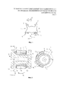
На Фиг.1 показан схематический вид сверху направляющего рычага по изобретению, содержащего резинометаллический шарнир,Figure 1 shows a schematic top view of a guide lever according to the invention, containing a rubber hinge,
На Фиг.2 показаны два поперечных сечения первого варианта выполнения резинометаллического шарнира,Figure 2 shows two cross sections of a first embodiment of a rubber-metal hinge,
На Фиг.3 показано поперечное сечение второго варианта выполнения резинометаллического шарнира,Figure 3 shows a cross section of a second embodiment of a rubber hinge,
На Фиг.4 показано поперечное сечение третьего варианта выполнения резинометаллического шарнира,Figure 4 shows a cross section of a third embodiment of a rubber hinge,
На Фиг.5 показан вид спереди демпфирующего резинового элемента резинометаллического шарнира, показанного на Фиг.4, иFigure 5 shows a front view of the damping rubber element of the rubber hinge shown in Figure 4, and
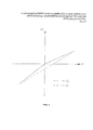
На Фиг.6 показан график характеристик крутящего момента в зависимости от вращения резинометаллического шарнира в направлении положительного и отрицательного схождения колес.Figure 6 shows a graph of the characteristics of the torque depending on the rotation of the rubber hinge in the direction of positive and negative toe.
На различных фигурах одни и те же элементы всегда имеют одинаковые ссылочные номера, поэтому эти элементы описаны только один раз.In different figures, the same elements always have the same reference numbers, therefore, these elements are described only once.
Осуществление изобретенияThe implementation of the invention
На Фиг.1 представлен схематический вид сверху направляющего рычага 1 по изобретению. Положение установки обозначено стрелкой 2 в направлении движения транспортного средства (не показано). В показанном примере направляющий рычаг 1 является торсионно-жестким поперечным рычагом и/или трапециевидным рычагом, содержащим две соединительные точки 3 на стороне кузова для присоединения трапециевидного рычага 1 к кузову автомобиля (не показан) или к вспомогательной раме, соединенной с кузовом автомобиля. Соединительная точка 3 на левой стороне тела рычага является передней внутренней соединительной точкой, наблюдаемой по направлению движения 2, а соединительная точка 3 на правой стороне является задней внутренней соединительной точкой.Figure 1 presents a schematic top view of the
Более того, направляющий рычаг и/или трапециевидный рычаг 1 также имеет две соединительные точки 4 на стороне колеса для соединения со стойкой 5 колеса. Стойка 5 колеса представлена на Фиг.1 только схематически. Аналогично соединительным точкам 3 на стороне кузова различаются передние наружные соединительные точки 4 на стороне колеса, наблюдаемые по направлению движения 2 (соединительная точка 4 слева на Фиг.1) и задняя наружная соединительная точка 4 (соединительная точка 4 справа на Фиг.1). В представленном на Фиг.1 примере по меньшей мере задняя соединительная точка 4 со стороны колеса содержит резинометаллический шарнир 6 по изобретению. Первый вариант выполнения резинометаллического шарнира 6 далее будет подробно описан со ссылкой на Фиг.2.Moreover, the guide lever and / or
На Фиг.2 представлены два поперечных сечения первого варианта выполнения резинометаллического шарнира 6. На виде слева показано сечение резинометаллического шарнира 6 по его продольной оси 7, которая совпадает с осью X согласно приведенным на Фиг.2 трем координатным осям X, Y и Z. На Фиг.2, вид справа, показан резинометаллический шарнир 6 в поперечном сечении, выполненном перпендикулярно к оси Х и/или продольной оси 7 вдоль линии разреза A-A, показанной на виде слева.Figure 2 shows two cross sections of the first embodiment of the
На продольном сечении резинометаллического шарнира 6 хорошо видны внешняя втулка 8 и внутренняя втулка 9, расположенная коаксиально. Между внешней втулкой 8 и внутренней втулкой 9 закреплена эластичная резиновая вставка 10, которая может быть, например, подвулканизирована к внешней втулке 8 и внутренней втулке 9 известным способом. Кроме того, внешняя втулка 8 имеет переднюю торцевую поверхность 11 и заднюю торцевую поверхность 12, которые, как можно хорошо увидеть на Фиг.2, в показанном варианте в каждом случае имеют фланцеобразную форму и расположены по существу под прямыми углами к продольной оси 7 резинометаллического шарнира 6. На Фиг.2 также показано, что по меньшей мере один передний эластичный демпфирующий резиновый элемент 13 соединен с передней торцевой поверхностью 11, и по меньшей мере один задний эластичный демпфирующий резиновый элемент 13 соединен с задней торцевой поверхностью 12. Передний и задний демпфирующие резиновые элементы 13 расположены асимметрично друг относительно друга. Согласно первому варианту выполнения, передние и задние демпфирующие резиновые элементы 13, в частности, расположены диаметрально друг относительно друга так, что резинометаллический шарнир 6 имеет асимметричную конструкцию на его торцевых поверхностях 11 и 12.On the longitudinal section of the rubber-
На правом поперечном сечении на Фиг.2 показан передний периферийный участок передней торцевой поверхности 11, на котором расположено несколько эластичных передних демпфирующих резиновых элементов 13. Передний периферийный участок находится, как это можно увидеть на поперечном сечении, на половине передней торцевой поверхности 11, проходящей слева от оси Z. В данном примере он занимает примерно половину всей торцевой поверхности 11. Таким образом, левая половина показанной передней торцевой поверхности 11 образует передний периферийный участок, на котором расположены эластичные передние демпфирующие резиновые элементы 13. Правая половина передней торцевой поверхности 11 не содержит передних демпфирующих резиновых элементов 13.2, a front peripheral portion of the
Как видно на правом изображении на Фиг.2, на переднем периферийном участке передней торцевой поверхности 11 на расстоянии друг от друга расположено четыре отдельных демпфирующих резиновых элемента 13. Демпфирующие свойства, в частности, общая эластичность и/или жесткость в осевом направлении передних демпфирующих резиновых элементов 13, расположенных на переднем периферийном участке передней торцевой поверхности 11, могут быть точно заданы с помощью регулирования количества передних демпфирующих резиновых элементов 13 и расстояния между ними.As can be seen in the right image in figure 2, on the front peripheral portion of the
На задней торцевой поверхности 12, аналогично передней торцевой поверхности 11, находится задний периферийный участок, на котором расположены задние демпфирующие резиновые элементы 13, причем задний периферийный участок расположен диаметрально относительно переднего периферийного участка. Диаметральное расположение переднего периферийного участка передней торцевой поверхности 11 относительно заднего периферийного участка задней торцевой поверхности 12 означает, что задняя торцевая поверхность 12 (на правом виде на Фиг.2 не показана) имеет зеркальное относительно оси Z расположение демпфирующих резиновых элементов 13 торцевой поверхности 11. Таким образом, задний периферийный участок задней торцевой поверхности 12, на котором расположены демпфирующие резиновые элементы 13, занимает примерно половину всей задней торцевой поверхности 12, причем задний периферийный участок расположен на правом изображении на Фиг.2 справа от оси Z. Диаметральное асимметричное расположение просматривается на левом виде на Фиг.2, на котором передний демпфирующий резиновый элемент 13 передней торцевой поверхности 11 показан слева вверху, а задний демпфирующий резиновый элемент 13 задней торцевой поверхности 12 справа внизу.On the
Также на левом виде на Фиг.2 показано, что демпфирующие резиновые элементы 13 имеют конусообразный профиль. В зависимости от крутизны боковых сторон и площади поперечного сечения отдельных демпфирующих резиновых элементов 13, дополнительно могут быть заданы модули эластичности каждого отдельного демпфирующего резинового элемента 13, выполняющего при сжатии функцию пружины. За счет этого может быть установлена требуемая характеристика отклика резинометаллического шарнира 6 по изобретению на осевое усилие. По существу, чем острее конусообразная форма каждого отдельного демпфирующего резинового элемента 13, тем меньше его модуль эластичности, в частности в начале сжатия. Чем меньше модуль эластичности демпфирующего резинового элемента 13, тем более упруго реагирует резинометаллический шарнир на осевые усилия, то есть вокруг оси Z меньший крутящий момент 14 изначально создается осевыми силами, действующими, например, в направлении движения 2 и асимметричным расположением передних и задних демпфирующих резиновых элементов 13.Also in the left view in FIG. 2, it is shown that the damping
Также на левом виде на Фиг.2 слева по направлению движения 2 находится передний опорный кронштейн 15, а справа по направлению движения 2 показан задний опорный кронштейн 16 трапециевидного рычага 1, показанного на Фиг.1. С помощью опорных кронштейнов 15, 16 резинометаллический шарнир 6 удерживается и фиксируется на трапециевидном рычаге 1 известным способом, например с помощью болта или винта, проходящего через внутреннюю втулку 9 и удерживаемого опорными кронштейнами 15, 16. В примере, показанном на Фиг.2, передние и задние демпфирующие резиновые элементы 13 в установленном ненагруженном состоянии расположены по существу без зазора между торцевыми поверхностями 11, 12 и соответствующими опорными кронштейнами 15 и/или 16. В результате достигается быстрый отклик резинометаллического шарнира 6 на изменение направления движения автомобиля или ускорение и/или замедление/торможение. Быстрый и точный отклик на сигналы рулевого управления является важной составляющей устойчивости автомобиля на поворотах.Also, in the left view of FIG. 2, the
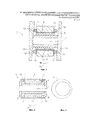
На Фиг.3 показано поперечное сечение второго варианта выполнения резинометаллического шарнира 17. Резинометаллический шарнир 17 отличается от резинометаллического шарнира 6, показанного на Фиг.2, по существу тем, что к передней торцевой поверхности 11 присоединены по меньшей мере два передних демпфирующих резиновых элемента 13, 18 различной высоты в направлении оси резинометаллического шарнира 17, а к задней торцевой поверхности 12 присоединены по меньшей мере два задних демпфирующих резиновых элемента 13, 18 различной высоты в направлении оси резинометаллического шарнира 17. Передние и задние демпфирующие резиновые элементы 13, и передние и задние демпфирующие резиновые элементы 18 имеют попарно одинаковую высоту, причем демпфирующие резиновые элементы 13 и 18 одинаковой высоты расположены асимметрично друг относительно друга на передней и задней торцевых поверхностях 11 и 12. Передние и задние демпфирующие резиновые элементы 18 имеют по сравнению с передними и задними демпфирующими резиновыми элементами 13 меньшую высоту по направлению оси резинометаллического шарнира 17. Передние и задние демпфирующие резиновые элементы 13 имеют такую высоту, что в установленном положении резинометаллического шарнира 17 они примыкают по существу без зазора к соответствующим переднему и заднему опорным кронштейнам 15 или 16. Передние и задние демпфирующие резиновые элементы 18, напротив, в установленном положении резинометаллического шарнира 17 находятся на определенном расстоянии от соответствующих опорных кронштейнов 15 или 16. Таким образом, резинометаллический шарнир 17 под воздействием осевых усилий будет реагировать аналогично резинометаллическому шарниру 6, то есть поворачиваться в направлении 14.FIG. 3 shows a cross section of a second embodiment of the
Различное расстояние между передними и задними демпфирующими резиновыми элементами 13 и/или 18 и опорными кронштейнами 15 и 16 в качестве альтернативы или дополнительно может быть выполнено с помощью опорных кронштейнов 15 и 16, как показано на Фиг.3, которые имеют различное расстояние до переднего и заднего демпфирующих резиновых элементов 13 и 18. Для этого опорные кронштейны 15 и 16 в области передних и задних демпфирующих резиновых элементов 13 расположены ближе к демпфирующим резиновым элементам 13, чем к передним и задним демпфирующим резиновым элементам 18, от которых они расположены на определенном расстоянии.Different distances between the front and rear damping
На Фиг.4 показано поперечное сечение третьего варианта резинометаллического шарнира 19 по изобретению. В резинометаллическом шарнире 19 передние и задние демпфирующие резиновые элементы 13 выполнены в форме резинового кольца 20. Резиновое кольцо 20 имеет асимметричную осевую жесткость. Как можно видеть на Фиг.5, где показан вид спереди резинового кольца 20 резинометаллического шарнира 19 с Фиг.4, асимметричная осевая жесткость конструкции достигается за счет того, что ширина резинового кольца по его контуру не является постоянной. Как показано на Фиг.4, передний демпфирующий резиновый элемент в форме резинового кольца 20 и задний демпфирующий резиновый элемент в форме резинового кольца 20 резинометаллического шарнира 19 также расположены асимметрично друг относительно друга. На Фиг.4 передний (левый) демпфирующий резиновый элемент в форме резинового кольца 20 расположен таким образом, что сверху он имеет в основном большую ширину, чем снизу. Задний (правый) демпфирующий резиновый элемент в форме резинового кольца 20 имеет, напротив, снизу большую ширину, чем сверху. Таким образом, резинометаллический шарнир 19 в ответ на действие осевых усилий ведет себя аналогично ранее описанным резинометаллическим шарнирам, то есть поворачивается в направлении 14.4 shows a cross section of a third embodiment of a
На Фиг.6 показан график зависимости характеристик крутящего момента от поворота резинометаллического шарнира в направлении положительного и отрицательного схождения колес. По оси абсцисс 24 системы координат отложен угол карданного поворота резинометаллического шарнира в положительном направлении (то есть на Фиг.6 направление направо), который отвечает за положительное схождение колес, и угол карданного поворота резинометаллического шарнира в отрицательном направлении (налево), который отвечает за отрицательное схождение колес. По оси ординат 21 отложен создаваемый резинометаллическим шарниром эффективный крутящий момент в зависимости от угла поворота резинометаллического шарнира. Как показано на Фиг.6, кривая 22 асимметричной жесткости и кривая 23 асимметричного предварительного напряжения показывают меньший крутящий момент для положительного схождения колес, чем для отрицательного. Иными словами, при воздействии осевых усилий, вызывающих крутящий момент в резинометаллический шарнире, шарнир легче смещается в направлении положительного схождения колес, чем в направлении отрицательного схождения колес. Кривая 22 соответствует резинометаллическому шарниру с одним передним и задним демпфирующими резиновыми элементами, имеющими асимметричную осевую жесткость, как было описано в отношении третьего варианта выполнения резинометаллического шарнира 19. Кривая 23 соответствует демпфирующей резиновой части, имеющей дополнительно к асимметричному расположению переднего и заднего демпфирующих резиновых элементов предварительное напряжение в направлении положительного схождения колес. Это может быть достигнуто за счет того, что передние и задние демпфирующие резиновые элементы 13 резинометаллического шарнира 6 или 17, соприкасающиеся с опорными кронштейнами 15 и 16, в установленном состоянии уже были слегка сжаты и/или под напряжением под воздействием кронштейнов 15, 16.Figure 6 shows a graph of the characteristics of the torque from the rotation of the rubber hinge in the direction of positive and negative toe. On the
Резинометаллический шарнир, трапециевидный рычаг и подвеска колес не ограничиваются приведенными вариантами выполнения и предполагают возможность других вариантов выполнения, действующих аналогичным образом. Так, эластичный корпус может быть приклеен, запрессован или жестко вставлен между внутренней и внешней втулками. Демпфирующие резиновые элементы сектора окружности передней и/или задней торцевых поверхностей могут иметь различную длину и/или ширину и/или высоту, также как и различный конусообразный профиль и/или поперечное сечение.The rubber-metal hinge, trapezoidal lever and suspension of the wheels are not limited to the given variants of execution and suggest the possibility of other variants of execution, acting in a similar way. Thus, the elastic housing can be glued, pressed in or rigidly inserted between the inner and outer bushings. The damping rubber elements of the sector of the circumference of the front and / or rear end surfaces may have different lengths and / or widths and / or heights, as well as different conical profiles and / or cross sections.
Согласно предпочтительному варианту, резинометаллический шарнир используют в трапециевидном рычаге, имеющем две соединительные точки на стороне кузова автомобиля для соединения трапециевидного рычага с кузовом или с вспомогательной рамой, соединенной с кузовом автомобиля. Рычаг также имеет две соединительные точки на стороне колеса, причем резинометаллический шарнир устанавливается по меньшей мере на задней соединительной точке на стороне колеса для шарнирного соединения трапециевидного рычага с шарниром стойки колеса. Такой трапециевидный рычаг предпочтительно использовать в независимой подвеске колес для соединения со стойкой колеса.According to a preferred embodiment, the rubber hinge is used in a trapezoidal arm having two connecting points on the side of the car body to connect the trapezoidal arm to the body or to an auxiliary frame connected to the car body. The lever also has two connecting points on the side of the wheel, the rubber mount being mounted at least on the rear connecting point on the side of the wheel for articulating the trapezoidal lever with the hinge of the wheel strut. Such a trapezoidal lever is preferably used in an independent suspension of wheels for connection with a wheel strut.
Перечень условных обозначений:List of conventions:
1 Направляющий рычаг колес1 Wheel Guide
2 Стрелка направления движения автомобиля2 Car direction arrow
3 Соединительная точка направляющего рычага на стороне кузова автомобиля3 Connecting point of the guide lever on the side of the car body
4 Соединительная точка направляющего рычага на стороне колеса4 Connecting point of the steering lever on the wheel side
5 Стойка колеса5 Wheel stand
6 Резинометаллический шарнир6 Rubber joint
7 Ось X, продольная ось резинометаллического шарнира7 X axis, longitudinal axis of the rubber joint
8 Внешняя втулка8 outer sleeve
9 Внутренняя втулка9 Inner sleeve
10 Резиновая вставка10 Rubber insert
11 Передняя торцевая поверхность внешней втулки11 Front end surface of the outer sleeve
12 Задняя торцевая поверхность внешней втулки12 Rear end surface of the outer sleeve
13 Демпфирующие резиновые элементы13 Damping rubber elements
14 Крутящий момент14 Torque
15 Передний опорный кронштейн15 Front support bracket
16 Задний опорный кронштейн16 Rear support bracket
17 Резинометаллический шарнир17 Rubber joint
18 Демпфирующие резиновые элементы18 Damping rubber elements
19 Резинометаллический шарнир19 Rubber joint
20 Резиновое кольцо20 rubber ring
21 Ось ординат21 ordinate axis
22 Кривая асимметричной жесткости22 asymmetric stiffness curve
23 Кривая асимметричного предварительного напряжения23 Asymmetric prestress curve
24 Ось абсцисс.24 x-axis.
Claims (9)
Applications Claiming Priority (2)
| Application Number | Priority Date | Filing Date | Title |
|---|---|---|---|
| DE102012200001A DE102012200001A1 (en) | 2012-01-02 | 2012-01-02 | Rubber-metal bearing for trapezoidal-link in wheel suspension, has rubber elastic body fastened and arranged between outer bush and inner bush, where outer bush has front end surface at which leading elastic damping element is mounted |
| DE102012200001.1 | 2012-01-02 |
Publications (2)
| Publication Number | Publication Date |
|---|---|
| RU2012158018A RU2012158018A (en) | 2014-07-10 |
| RU2617243C2 true RU2617243C2 (en) | 2017-04-24 |
Family
ID=48608051
Family Applications (1)
| Application Number | Title | Priority Date | Filing Date |
|---|---|---|---|
| RU2012158018A RU2617243C2 (en) | 2012-01-02 | 2012-12-28 | Rubber-steel hinge for car wheels suspension, trapezoidal lever arm of suspension and wheel suspension |
Country Status (5)
| Country | Link |
|---|---|
| US (1) | US8973931B2 (en) |
| CN (1) | CN103185068B (en) |
| BR (1) | BR102012033003A2 (en) |
| DE (1) | DE102012200001A1 (en) |
| RU (1) | RU2617243C2 (en) |
Families Citing this family (18)
| Publication number | Priority date | Publication date | Assignee | Title |
|---|---|---|---|---|
| JP6088286B2 (en) * | 2013-02-25 | 2017-03-01 | 株式会社ブリヂストン | Vibration isolator |
| US20160114641A1 (en) * | 2013-05-28 | 2016-04-28 | Toray Industries, Inc. | Vehicle link component, and manufacturing method therefor |
| GB2526511B (en) | 2014-03-14 | 2019-06-12 | British Gas Trading Ltd | Apparatus and method for control of thermal appliances |
| JP6348766B2 (en) * | 2014-04-28 | 2018-06-27 | ダイハツ工業株式会社 | Vehicle suspension |
| US9649902B2 (en) * | 2015-05-22 | 2017-05-16 | Fca Us Llc | Link assembly for longitudinal arm vehicle suspension |
| KR101822264B1 (en) * | 2016-03-28 | 2018-01-26 | 현대자동차주식회사 | Mounting apparatus of trailing arm |
| WO2019131509A1 (en) * | 2017-12-28 | 2019-07-04 | Toyo Tire株式会社 | Arrangement structure of electric automobile vibration isolating device |
| EP3781834A1 (en) * | 2018-04-17 | 2021-02-24 | Cooper Standard France | Articulating element for filtering and damping vibrations and articulating device |
| DE102018118340B4 (en) * | 2018-07-30 | 2024-03-28 | Saf-Holland Gmbh | Commercial vehicle axle suspension |
| CN109094315A (en) * | 2018-08-16 | 2018-12-28 | 安徽奥丰汽车配件有限公司 | A kind of automobile chassis combination rubber bushing |
| CN110966341B (en) * | 2018-09-29 | 2024-07-23 | 上汽通用五菱汽车股份有限公司 | Front vibration reduction strut seat assembly |
| DE102018125459A1 (en) | 2018-10-15 | 2020-04-16 | Bayerische Motoren Werke Aktiengesellschaft | Mounting arrangement of a vibration damper |
| DE102019203836A1 (en) * | 2019-03-20 | 2020-09-24 | Audi Ag | Wheel suspension for a vehicle axle |
| DE102019109212A1 (en) * | 2019-04-08 | 2020-10-08 | Vibracoustic Ag | Hydraulically damping bearing |
| DE102019120369B3 (en) * | 2019-07-29 | 2020-11-05 | Benteler Automobiltechnik Gmbh | Chassis component |
| CN110793702B (en) * | 2019-11-12 | 2021-06-18 | 中车大连机车车辆有限公司 | Indirect measurement method of transverse force of wheel track and method for determining radius of curve track |
| DE102020007681B3 (en) * | 2020-12-15 | 2022-05-05 | Sumitomo Riko Company Limited | Bearing, outer sleeve and method of making a bearing |
| CN114810916B (en) * | 2022-04-26 | 2023-06-23 | 博戈橡胶塑料(株洲)有限公司 | Hydraulic bushing capable of adjusting static stiffness curve and assembling method thereof |
Citations (4)
| Publication number | Priority date | Publication date | Assignee | Title |
|---|---|---|---|---|
| US5246248A (en) * | 1992-05-15 | 1993-09-21 | General Motors Corporation | Vehicle rear suspension apparatus |
| US5899431A (en) * | 1995-02-28 | 1999-05-04 | Automobiles Peugeot | Elastic articulation especially for a motor vehicle wheel and axle assembly |
| US6099005A (en) * | 1996-05-31 | 2000-08-08 | Toyota Jidosha Kabushiki Kaisha | Rear suspension system of automobile discriminative of road irregularities and wheel braking |
| JP2006160008A (en) * | 2004-12-03 | 2006-06-22 | Nissan Motor Co Ltd | Suspension arm supporting structure |
Family Cites Families (25)
| Publication number | Priority date | Publication date | Assignee | Title |
|---|---|---|---|---|
| US1913513A (en) * | 1929-11-11 | 1933-06-13 | Delco Prod Corp | Oscillating pivot joint |
| US2238197A (en) * | 1938-09-15 | 1941-04-15 | John Warren Watson Company | Bearing structure |
| US2608751A (en) * | 1946-04-15 | 1952-09-02 | Silentbloc | Method of assembling resilient bearings |
| DE972181C (en) * | 1953-07-02 | 1959-06-04 | Daimler Benz Ag | Torsion bar suspension for vehicles, in particular motor vehicles |
| US3152846A (en) * | 1962-07-13 | 1964-10-13 | Champ Items Inc | Replacement kit for defective bearings |
| US3473820A (en) * | 1967-05-18 | 1969-10-21 | Harsco Corp | Multiple axle system for vehicles |
| JPS5830725Y2 (en) * | 1977-12-28 | 1983-07-07 | 本田技研工業株式会社 | Vehicle rear wheel suspension system |
| JPS57167808A (en) * | 1981-04-07 | 1982-10-15 | Toyota Motor Corp | Adjusting device of alignment for vehicle |
| US4603882A (en) | 1982-04-28 | 1986-08-05 | Mazda Motor Corporation | Vehicle rear suspension mechanism |
| US4529221A (en) * | 1982-04-30 | 1985-07-16 | Mazda Motor Corporation | Vehicle rear suspension mechanism |
| DE3306432C2 (en) | 1983-02-24 | 1986-12-11 | Ford-Werke AG, 5000 Köln | Independent wheel suspension for non-steered wheels of motor vehicles |
| DE3333706C2 (en) * | 1983-09-17 | 1986-09-04 | Bayerische Motoren Werke AG, 8000 München | Suspension of a rigid axle for vehicles |
| DE3346665A1 (en) * | 1983-12-23 | 1985-07-04 | Lemförder Metallwaren AG, 2844 Lemförde | ELASTIC BEARING WITH FORCED GUIDE |
| US4848788A (en) * | 1984-11-15 | 1989-07-18 | Ford Motor Company | Independent rear wheel suspension with offset connection between upper control arm and wheel carrier |
| JPH0645283B2 (en) * | 1985-01-28 | 1994-06-15 | トヨタ自動車株式会社 | Rear suspension of the vehicle |
| DE4305808C2 (en) * | 1993-02-25 | 1995-05-11 | Freudenberg Carl Fa | Hydraulically damping sleeve rubber spring |
| JP3725346B2 (en) * | 1998-09-02 | 2005-12-07 | 東洋ゴム工業株式会社 | Anti-vibration mount |
| GB2370257B (en) | 2000-12-22 | 2004-04-21 | Mg Rover Group Ltd | Vehicle suspension systems |
| FR2818718B1 (en) * | 2000-12-22 | 2003-07-25 | Hutchinson | ANTI-VIBRATION SLEEVE AND MOTOR VEHICLE HAVING SUCH A SLEEVE |
| KR100461602B1 (en) * | 2001-12-17 | 2004-12-14 | 기아자동차주식회사 | Bush for suspension of vehicle |
| US7360756B2 (en) * | 2005-03-31 | 2008-04-22 | Delphi Technologies, Inc. | Vibration isolating bushing with embedded speed/position sensor |
| DE102005047868A1 (en) * | 2005-10-05 | 2007-07-05 | Zf Friedrichshafen Ag | Guide element for a guideway element in a wheel suspension of a vehicle |
| US7789406B2 (en) * | 2007-04-04 | 2010-09-07 | Nissan Motor Co. Ltd. | Suspension device and method for supporting wheels |
| JP4865637B2 (en) * | 2007-05-18 | 2012-02-01 | 本田技研工業株式会社 | Cylindrical vibration isolator |
| US7726674B2 (en) * | 2008-05-08 | 2010-06-01 | Air Suspensions, Inc. | Suspension assembly |
-
2012
- 2012-01-02 DE DE102012200001A patent/DE102012200001A1/en not_active Ceased
- 2012-12-21 BR BR102012033003A patent/BR102012033003A2/en not_active Application Discontinuation
- 2012-12-28 US US13/729,558 patent/US8973931B2/en active Active
- 2012-12-28 RU RU2012158018A patent/RU2617243C2/en not_active IP Right Cessation
- 2012-12-29 CN CN201210592665.7A patent/CN103185068B/en active Active
Patent Citations (4)
| Publication number | Priority date | Publication date | Assignee | Title |
|---|---|---|---|---|
| US5246248A (en) * | 1992-05-15 | 1993-09-21 | General Motors Corporation | Vehicle rear suspension apparatus |
| US5899431A (en) * | 1995-02-28 | 1999-05-04 | Automobiles Peugeot | Elastic articulation especially for a motor vehicle wheel and axle assembly |
| US6099005A (en) * | 1996-05-31 | 2000-08-08 | Toyota Jidosha Kabushiki Kaisha | Rear suspension system of automobile discriminative of road irregularities and wheel braking |
| JP2006160008A (en) * | 2004-12-03 | 2006-06-22 | Nissan Motor Co Ltd | Suspension arm supporting structure |
Also Published As
| Publication number | Publication date |
|---|---|
| CN103185068B (en) | 2017-05-10 |
| US8973931B2 (en) | 2015-03-10 |
| CN103185068A (en) | 2013-07-03 |
| BR102012033003A2 (en) | 2015-12-15 |
| DE102012200001A1 (en) | 2013-07-04 |
| RU2012158018A (en) | 2014-07-10 |
| US20130200587A1 (en) | 2013-08-08 |
Similar Documents
| Publication | Publication Date | Title |
|---|---|---|
| RU2617243C2 (en) | Rubber-steel hinge for car wheels suspension, trapezoidal lever arm of suspension and wheel suspension | |
| US6254114B1 (en) | Composite stabilizer bar link | |
| US9174505B2 (en) | Vehicle independent suspension | |
| KR102387695B1 (en) | Vehicle suspension | |
| EP2581241A1 (en) | Single-shaft damping joint for connecting vehicle chassis parts | |
| US8302980B2 (en) | Eccentric steering axis strut top mount | |
| JP5693739B2 (en) | Hybrid cross-axis ball joint bush | |
| CN102216096A (en) | A vehicle suspension | |
| US9096111B2 (en) | Coupled torsion beam axle type suspension system | |
| CN110023117B (en) | Suspension device for vehicle | |
| EP2524824A2 (en) | Suspension structure and method of making suspension link | |
| US20170097040A1 (en) | Chassis bearing | |
| CN105102246B (en) | For the vehicle bridge guide bearing being coupled in back axle on the vehicle structure of motor vehicle | |
| JP2000085330A (en) | Rear suspension unit for vehicle | |
| JP6384506B2 (en) | Car suspension system | |
| CN107921836B (en) | Suspension device for at least one rear wheel of a motor vehicle | |
| JP2003205720A (en) | Elastic bush for suspension device | |
| JP7501955B2 (en) | Elastic bush support structure | |
| JPS62175208A (en) | Rear suspension device for vehicle | |
| KR20120008877A (en) | Strut type suspension system for vehicle | |
| KR20080023557A (en) | Strut mount structure of suspension for automobile | |
| JP2001041234A (en) | Pillow ball bush | |
| KR100291056B1 (en) | Insulator for mcpherson type suspension system | |
| JP2003118345A (en) | Strut type suspension device | |
| KR101257821B1 (en) | Stabilizer bar bush in vehicle and manufacturing method thereof |
Legal Events
| Date | Code | Title | Description |
|---|---|---|---|
| HE9A | Changing address for correspondence with an applicant | ||
| HE9A | Changing address for correspondence with an applicant | ||
| MM4A | The patent is invalid due to non-payment of fees |
Effective date: 20171229 |
|
| NF4A | Reinstatement of patent |
Effective date: 20190128 |
|
| MM4A | The patent is invalid due to non-payment of fees |
Effective date: 20201229 |