RU2614432C2 - Method and system for aircraft piloting control with rear-mounted propulsion unit - Google Patents
Method and system for aircraft piloting control with rear-mounted propulsion unit Download PDFInfo
- Publication number
- RU2614432C2 RU2614432C2 RU2013137663A RU2013137663A RU2614432C2 RU 2614432 C2 RU2614432 C2 RU 2614432C2 RU 2013137663 A RU2013137663 A RU 2013137663A RU 2013137663 A RU2013137663 A RU 2013137663A RU 2614432 C2 RU2614432 C2 RU 2614432C2
- Authority
- RU
- Russia
- Prior art keywords
- orientation
- deformation
- point
- rear end
- aircraft
- Prior art date
Links
- 238000000034 method Methods 0.000 title claims description 8
- 230000007935 neutral effect Effects 0.000 claims description 11
- 238000013461 design Methods 0.000 abstract description 4
- 230000000694 effects Effects 0.000 abstract 1
- 239000000126 substance Substances 0.000 abstract 1
- 230000003313 weakening effect Effects 0.000 abstract 1
- 238000005259 measurement Methods 0.000 description 19
- 230000005489 elastic deformation Effects 0.000 description 10
- 230000010355 oscillation Effects 0.000 description 5
- 238000001914 filtration Methods 0.000 description 4
- 230000006641 stabilisation Effects 0.000 description 3
- 238000011105 stabilization Methods 0.000 description 3
- 238000012937 correction Methods 0.000 description 2
- 230000001133 acceleration Effects 0.000 description 1
- 230000009286 beneficial effect Effects 0.000 description 1
- 230000001276 controlling effect Effects 0.000 description 1
- 235000019788 craving Nutrition 0.000 description 1
- 238000013016 damping Methods 0.000 description 1
- 230000001687 destabilization Effects 0.000 description 1
- 238000004519 manufacturing process Methods 0.000 description 1
- 230000001105 regulatory effect Effects 0.000 description 1
- 230000000087 stabilizing effect Effects 0.000 description 1
- 238000012546 transfer Methods 0.000 description 1
Images

Classifications
-
- B—PERFORMING OPERATIONS; TRANSPORTING
- B64—AIRCRAFT; AVIATION; COSMONAUTICS
- B64G—COSMONAUTICS; VEHICLES OR EQUIPMENT THEREFOR
- B64G1/00—Cosmonautic vehicles
- B64G1/22—Parts of, or equipment specially adapted for fitting in or to, cosmonautic vehicles
- B64G1/40—Arrangements or adaptations of propulsion systems
-
- B—PERFORMING OPERATIONS; TRANSPORTING
- B64—AIRCRAFT; AVIATION; COSMONAUTICS
- B64G—COSMONAUTICS; VEHICLES OR EQUIPMENT THEREFOR
- B64G1/00—Cosmonautic vehicles
- B64G1/22—Parts of, or equipment specially adapted for fitting in or to, cosmonautic vehicles
- B64G1/24—Guiding or controlling apparatus, e.g. for attitude control
- B64G1/26—Guiding or controlling apparatus, e.g. for attitude control using jets
-
- B—PERFORMING OPERATIONS; TRANSPORTING
- B64—AIRCRAFT; AVIATION; COSMONAUTICS
- B64G—COSMONAUTICS; VEHICLES OR EQUIPMENT THEREFOR
- B64G1/00—Cosmonautic vehicles
- B64G1/002—Launch systems
-
- B—PERFORMING OPERATIONS; TRANSPORTING
- B64—AIRCRAFT; AVIATION; COSMONAUTICS
- B64G—COSMONAUTICS; VEHICLES OR EQUIPMENT THEREFOR
- B64G1/00—Cosmonautic vehicles
- B64G1/22—Parts of, or equipment specially adapted for fitting in or to, cosmonautic vehicles
- B64G1/24—Guiding or controlling apparatus, e.g. for attitude control
- B64G1/38—Guiding or controlling apparatus, e.g. for attitude control damping of oscillations, e.g. nutation dampers
-
- G—PHYSICS
- G05—CONTROLLING; REGULATING
- G05D—SYSTEMS FOR CONTROLLING OR REGULATING NON-ELECTRIC VARIABLES
- G05D1/00—Control of position, course or altitude of land, water, air, or space vehicles, e.g. automatic pilot
- G05D1/10—Simultaneous control of position or course in three dimensions
- G05D1/107—Simultaneous control of position or course in three dimensions specially adapted for missiles
Abstract
Description
Настоящее изобретение относится к способу и системе пилотирования летательного аппарата с двигательным агрегатом с задним расположением.The present invention relates to a method and system for piloting an aircraft with a rear-mounted propulsion system.
Известно, что летательный аппарат, такой как ракета-носитель, может управляться по меньшей мере одним ориентируемым двигательным агрегатом, установленным на заднем конце аппарата. Этот двигательный агрегат расположен таким образом, чтобы создавать тягу, интенсивность и направление которой определяют траекторию полета аппарата.It is known that an aircraft, such as a launch vehicle, can be controlled by at least one orientable propulsion unit mounted at the rear end of the device. This propulsion unit is positioned so as to create traction, the intensity and direction of which determine the flight path of the vehicle.
Также известно, что в передней части такого летательного аппарата обычно расположен блок инерциальных измерений, одной из функций которого является определение ориентации аппарата, т.е. его ориентации относительно инерциальных осей (отсчета), заложенных в блок инерциальных измерений. В частности, исходя из этого, компьютер определяет ориентацию, которая должна быть придана двигательному агрегату с задним расположением таким образом, чтобы создаваемая им тяга позволяла аппарату стабильно двигаться по траектории полета. Эта ориентация придается двигательному агрегату с задним расположением посредством сервоконтура, алгоритм управления которым традиционно задает зависимость между направлением тягового усилия, которое двигательный агрегат должен сообщать аппарату, и ориентацией аппарата, определенной блоком инерциальных измерений.It is also known that in the front of such an aircraft there is usually a block of inertial measurements, one of the functions of which is to determine the orientation of the device, i.e. its orientation relative to the inertial axes (reference) embedded in the inertial measurement unit. In particular, based on this, the computer determines the orientation that should be given to the engine unit with a rear location so that the thrust created by it allows the device to move stably along the flight path. This orientation is imparted to the motor unit with a rear arrangement by means of a servo circuit, the control algorithm of which traditionally defines the relationship between the direction of the tractive effort that the motor unit must communicate to the device and the orientation of the device determined by the inertial measurement unit.
Оснащенный таким образом летательный аппарат может в реальном времени пилотироваться в полете с возможностью регулирования и стабилизации его траектории независимо от условий полета (атмосферного, орбитального и т.д.).An aircraft equipped in this way can be piloted in real time in flight with the possibility of regulating and stabilizing its trajectory regardless of flight conditions (atmospheric, orbital, etc.).
Тем не менее, поскольку жесткость конструкции аппарата этого типа обычно не является бесконечной, вероятно, что она испытывает колебательные упругие деформации. Эти деформации нарушают алгоритм управления сервоконтуром аппарата вследствие напряженно-деформированных состояний на различных частотах и с различными затуханиями. Кроме того, нарушение алгоритма управления может приводить к дестабилизации аппарата.Nevertheless, since the structural rigidity of this type of apparatus is usually not infinite, it is likely that it experiences vibrational elastic deformations. These deformations violate the control algorithm of the servo circuit of the apparatus due to stress-strain states at different frequencies and with different attenuations. In addition, a violation of the control algorithm can lead to destabilization of the apparatus.
С целью стабилизации аппарата в случае таких напряженно-деформированных состояний известно применение фильтрации управления ориентацией двигательного агрегата, которая определяется компьютером в зависимости от предшествующей ориентации аппарата, определенной блоком инерциальных измерений, в результате чего упомянутые напряженно-деформированные состояния ослабляются.In order to stabilize the apparatus in the case of such stress-strain states, it is known to use filtering to control the orientation of the motor unit, which is determined by the computer depending on the previous orientation of the apparatus, determined by the inertial measurement unit, as a result of which the stress-strain states are weakened.
Аналогичным образом, известно применение фильтрации управления ориентацией двигательного агрегата, которая определяется компьютером, с целью, с одной стороны, препятствовать упомянутой ориентации двигательного агрегата, а с другой стороны, деформации, вызванной напряженно-деформированным состоянием на заданной частоте.Similarly, it is known to use filtering to control the orientation of a motor unit, which is determined by a computer, with the goal, on the one hand, of preventing said orientation of a motor unit, and, on the other hand, of deformation caused by a stress-strain state at a given frequency.
Тем не менее, эти известные методы фильтрации неприменимы, когда частоты напряженно-деформированных состояний имеют такой же порядок величины, как и полоса пропускания, предназначенная для пилотирования (например, полоса пропускания, необходимая для обеспечения стабильности аппарата). В частности, когда деформация аппарата имеет форму колебаний с первой частотой в полосе пропускания, необходимой для обеспечения стабильности, пилотирование аппарата, вероятно, невозможно, поскольку при этом требуется одновременно выполнять, с одной стороны, требования управления общим движением аппарата (далее - "жесткая" форма колебаний), а с другой стороны, требования стабильности при напряженно-деформированных состояниях (упругой деформации, поскольку летательный аппарат не является абсолютно жестким).However, these known filtering methods are not applicable when the frequencies of stress-strain states are of the same order of magnitude as the passband intended for piloting (for example, the passband necessary to ensure the stability of the apparatus). In particular, when the deformation of the apparatus is in the form of vibrations with a first frequency in the passband necessary to ensure stability, piloting the apparatus is probably impossible, since it is necessary to simultaneously fulfill, on the one hand, the requirements for controlling the overall movement of the apparatus (hereinafter referred to as “rigid” oscillation mode), and on the other hand, the requirements of stability under stress-strain states (elastic deformation, since the aircraft is not absolutely rigid).
Соответственно, в основу настоящего изобретения положена задача создания способа пилотирования летательного аппарата с использованием двигательного устройства, которое может быть ориентировано относительно заднего конца аппарата, что позволяет направлять и стабилизировать аппарат независимо от условий полета, в том числе при воздействии на аппарат напряжений, способных упруго деформировать конструкцию аппарата посредством колебаний различных форм.Accordingly, the present invention is based on the task of creating a method of piloting an aircraft using a propulsion device that can be oriented relative to the rear end of the device, which allows you to direct and stabilize the device regardless of flight conditions, including when the device is subjected to stresses that can elastically deform apparatus design by means of vibrations of various forms.
С этой целью в изобретении предложен способ пилотирования летательного аппарата посредством двигательного устройства, которое может быть ориентировано относительно заднего конца аппарата, включающий определение ориентации аппарата с помощью сервоконтура и корректировку ориентации двигательного устройства в зависимости от результатов определения ориентации таким образом, чтобы стабилизировать аппарат на траектории его полета, отличающийся тем, что ориентацию аппарата определяют вблизи его заднего конца.To this end, the invention provides a method for piloting an aircraft by means of a propulsion device that can be oriented relative to the rear end of the apparatus, including determining the orientation of the apparatus using a servo circuit and adjusting the orientation of the propulsion device depending on the results of determining the orientation in such a way as to stabilize the apparatus on its trajectory flight, characterized in that the orientation of the apparatus is determined near its rear end.
Этим способом согласно изобретению управляют двигательным устройством и определяют ориентацию аппарата в точках в непосредственной близости от двигательного устройства. В результате, определяемая таким способом ориентация по меньшей мере преимущественно соответствует ориентации, которая должна быть придано аппарату и, соответственно, может непосредственно использоваться для управления двигательным устройством без необходимости адаптации ориентации, определяемой между передним и задним концами аппарата, что чревато нарушением алгоритма управления аппаратом.In this way according to the invention, the motor device is controlled and the orientation of the apparatus is determined at points in the immediate vicinity of the motor device. As a result, the orientation determined in this way at least predominantly corresponds to the orientation that should be given to the device and, accordingly, can be directly used to control the motor device without the need to adapt the orientation determined between the front and rear ends of the device, which is fraught with a violation of the control algorithm of the device.
Соответственно, путем тщательного размещения средства определения ориентации более эффективно контролируется нарушение (вызванное напряженно-деформированными состояниями) алгоритма управления аппаратом.Accordingly, by carefully placing the orientation determining means, the violation (caused by stress-strain states) of the apparatus control algorithm is more effectively controlled.
Кроме того, следует отметить, что изобретение, в частности, обеспечивает определенную степень свободы, теряемую при стабилизации аппарата, и широкий диапазон уровня его жесткости. Тем самым могут быть ослаблены конструктивные ограничения, более точно, ограничения по жесткости аппарата и дополнительно упрощено его изготовление.In addition, it should be noted that the invention, in particular, provides a certain degree of freedom that is lost during stabilization of the apparatus, and a wide range of levels of its rigidity. Thereby, structural constraints, more precisely, restrictions on the rigidity of the apparatus, can be loosened and its manufacture further simplified.
Если в соответствии с изобретением ориентация аппарата может определяться на его заднем конце, следует учесть, что с учетом упругой деформации конструкции аппарата еще более предпочтительно определять ориентацию максимально близко к точке, вокруг которой шарнирно установлено двигательное устройство.If, in accordance with the invention, the orientation of the apparatus can be determined at its rear end, it should be noted that, taking into account the elastic deformation of the apparatus structure, it is even more preferable to determine the orientation as close as possible to the point around which the motor device is pivotally mounted.
С целью улучшения стабильности аппарата при корректировке ориентации двигательного устройства учитываются угловые и линейные деформации на заднем конце аппарата и в месте определения ориентации.In order to improve the stability of the apparatus, when adjusting the orientation of the motor device, the angular and linear deformations at the rear end of the apparatus and at the location of the orientation are taken into account.
В этом случае с целью естественного контроля напряженно-деформированных состояний место определения ориентации определяется таким образом, чтобы независимо от деформации аппарата угловая деформация в месте определения ориентации и линейная деформация на заднем конце аппарата имели противоположные знаки.In this case, for the purpose of the natural control of stress-strain states, the location of the orientation is determined so that, regardless of the deformation of the apparatus, the angular deformation at the location of the determination of orientation and linear deformation at the rear end of the apparatus have opposite signs.
В качестве альтернативы, когда при заданной деформации аппарата угловая деформация в месте определения ориентации и линейная деформация на заднем конце аппарата имеют одинаковый знак, ориентация двигательного устройства корректируется с учетом такого знака.Alternatively, when for a given deformation of the apparatus, the angular deformation at the location of the orientation determination and the linear deformation at the rear end of the apparatus have the same sign, the orientation of the motor device is corrected for this sign.
Определение ориентации и корректировка ориентации двигательного устройства предпочтительно осуществляются последовательно в течение очень короткого периода времени. Тем самым гарантируется, что двигательного устройства угловая деформация в месте определения ориентации и линейная деформация на заднем конце аппарата не изменят знаки за время между определением ориентации и корректировкой ориентации.The orientation determination and orientation adjustment of the propulsion device are preferably carried out sequentially for a very short period of time. This ensures that the motor device angular deformation in the place of determination of orientation and linear deformation at the rear end of the apparatus will not change the signs during the time between the determination of orientation and correction of orientation.
В изобретении дополнительно предложена система пилотирования летательного аппарата, содержащая двигательное устройство, которое может быть ориентировано относительно заднего конца аппарата, средство определения ориентации аппарата, а также средство корректировки ориентации двигательного устройства в зависимости от результата определения ориентации таким образом, чтобы направлять аппарат по стабильной траектории, отличающаяся тем, что средство определения ориентации летательного аппарата расположено вблизи его заднего конца.The invention further provides an aircraft piloting system comprising a propulsion device that can be oriented relative to the rear end of the apparatus, means for determining the orientation of the apparatus, and also means for adjusting the orientation of the propulsion device depending on the result of determining the orientation so as to direct the apparatus along a stable path, characterized in that the means for determining the orientation of the aircraft is located near its rear end.
На прилагаемых чертежах ясно проиллюстрировано, как может быть реализовано изобретение. Одинаковые элементы обозначены одинаковыми позициями на чертежах.The accompanying drawings clearly illustrate how the invention can be implemented. Identical elements are denoted by the same reference numerals in the drawings.
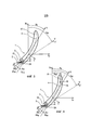
На фиг.1 показана известная система пилотирования летательного аппарата в нейтральной к тяге осевой плоскости аппарата.Figure 1 shows a known system for piloting an aircraft in a thrust-neutral axial plane of the apparatus.
На фиг.2 показана проиллюстрированная на фиг.1 известная система пилотирования в ситуации, когда летательный аппарат испытывает колебательную упругую деформацию (сила которой показана преувеличенной на фиг.2).Figure 2 shows the known piloting system illustrated in figure 1 in a situation where the aircraft is experiencing vibrational elastic deformation (the force of which is shown to be exaggerated in figure 2).
На фиг.3 показана система пилотирования согласно настоящему изобретению в такой же ситуации, которая проиллюстрирована на фиг.2.Figure 3 shows the piloting system according to the present invention in the same situation, which is illustrated in figure 2.
На фиг.4 показан вид, аналогичный виду на фиг.3, иллюстрирующий одну из разновидностей системы пилотирования согласно изобретению.Figure 4 shows a view similar to the view of figure 3, illustrating one of the varieties of the piloting system according to the invention.
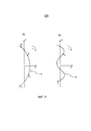
На фиг.5 показаны напряженно-деформированные состояния аппарата.Figure 5 shows the stress-strain state of the apparatus.
Показанный на фиг.1 летательный аппарат 1 известного типа, например ракета-носитель, оснащен двигательным устройством 2, рассчитанным на то, чтобы задавать направление тяги Р на заднем конце 1R аппарата. Это двигательное устройство 2 может быть шарнирно установлено вокруг точки Т сочленения на конце 1R аппарата таким образом, что направление тяги Р может быть задано вокруг точки Т сочленения. На фиг.1 показано, что направление тяги ориентировано под углом β относительно продольной оси X аппарата. Направление аппарата 1 по траектории (не показанной) достигается известным способом путем корректировки угла β относительно инерциальных осей Xo и Yo.Shown in figure 1, an
Управление траекторией аппарата 1 состоит в ориентации продольной оси Х аппарата 1 в желаемом направлении относительно инерциальных осей Хо и Yo путем воздействия на регулировку угла β.The control of the trajectory of the
Для управления тягой в зависимости от желаемой траектории полета необходимо в реальном времени определять положение и ориентацию аппарата 1. С этой целью аппарат 1 известным способом оснащен блоком 3 инерциальных измерений, находящимся в точке М в передней части 1F аппарата. Этот блок 3 регистрирует при запуске аппарата инерциальные осей Хо и Yo, которые служат опорными осями для блока 3. После этого в процессе движения аппарата 1 блок 3 с помощью измерительного средства 3А определяет ориентацию θM аппарата (заданную осями Х и Y аппарата в блоке 3) относительно инерциальных осей Хо и Yo, на основании чего компьютер вычисляет отклонение двигательного устройства 2 (которое задает ориентацию β тяги, прилагаемой к аппарату) таким образом, чтобы аппарат следовал по желаемой траектории полета, которая, в частности, должна являться стабильной.To control the thrust, depending on the desired flight path, it is necessary to determine in real time the position and orientation of the
Предполагается, что показанный на фиг.1 аппарат 1 имеет бесконечную жесткость, и его нейтральная ось 4 совпадает с продольной осью X. Таким образом, общий алгоритм управления, применимый к двигательному устройству 2, обычно формулируется в виде следующего уравнения (в котором θ означает разность между результатом определения ориентации θM и целевой ориентацией θR)It is assumed that the
![]()
![]()
Тем не менее, как показано в преувеличенном виде на фиг.2, конструкция аппарата 1 не является бесконечно жесткой, она может испытывать упругую деформацию под действием колебательных напряжений. Эта деформация имеет формы колебаний с различными частотами, две их которых проиллюстрированы на фиг.5 (форма колебаний первого порядка на фиг.5А и форма колебаний более высокого порядка на фиг.5Б). Как показано на фиг.2, поскольку аппарат 1 (и его нейтральная ось 4) имеют правильную кривизну, эта форма колебаний первого порядка является основной формой деформации.However, as shown in exaggerated form in figure 2, the design of the
Измерения, осуществляемые измерительным средством 3А блока инерциальных измерений 3, позволяют определять ориентацию θM аппарата в данном положении, которая соответствует угловому рассогласованию между осью X’ аппарата (видимой осью аппарата в точке М измерений) и инерциальной осью Хо. На основании этих данных компьютер вычисляет ориентацию β, которая должна быть придана двигательному устройству 2 относительно оси X’’ аппарата (видимой оси аппарата в точке Т сочленения). Тем не менее, вследствие деформации аппарата видимая ось X’ (аппарата в точке М измерений измерительным средством 3А блока 3 инерциальных измерений) и видимая ось X’’ (аппарата в точке Т сочленения) не параллельны друг другу или нейтральной оси 4 аппарата.The measurements performed by the measuring means 3A of the
В результате возникает:The result is:
угловая деформация δθM аппарата 1 в точке М измерений относительно нейтральной оси 4 аппарата,angular deformation δθ M of the
линейная деформация δyM аппарата 1 в точке М измерений относительно нейтральной оси 4 аппарата,linear deformation δy M of
угловая деформация δθT аппарата 1 в точке Т сочленения тяги относительно нейтральной оси 4 аппарата, иangular deformation δθ T of the
линейная деформация δyT аппарата 1 в точке Т сочленения относительно нейтральной оси 4 аппарата.linear deformation δy T of the
Каждая форма колебаний деформации имеет импульс ω и коэффициент ξ затухания. Соответственно, влияние деформации конструкции аппарата при форме колебаний энного порядка может быть представлено в виде следующей системы уравнений:Each deformation vibration form has a momentum ω and a damping coefficient ξ. Accordingly, the influence of the deformation of the apparatus structure in the form of oscillations of the nth order can be represented as the following system of equations:
![]()
![]()
![]()
![]()
![]()
![]()
![]()
![]()
При этом q является решением следующего уравнения:Moreover, q is a solution to the following equation:
![]()
![]()
путем решения которого обеспечивается новый алгоритм управления:by solving which a new control algorithm is provided:
![]()
![]()
По сравнению с традиционным алгоритмом управления согласно Уравнению 1 этот алгоритм управления содержит дополнительный компонент 
Чтобы стабилизировать каждую форму колебаний упругой деформации, измерительное средство 3А помещают вблизи точки Т, вокруг которой шарнирно установлено двигательное устройство 2. Эта ситуация проиллюстрирована на фиг.3.In order to stabilize each waveform of elastic deformation, the measuring means 3A is placed near point T, around which the
Следует отметить, что усовершенствование, проиллюстрированное в этом случае, является моделью рассогласования, содержащей принятые неправильные употребления системы обозначений (θ записывается вместе Δθ, θM вместе с ΔθM, Δβ вместе с β).It should be noted that the improvement illustrated in this case is a mismatch model containing accepted misuse of the notation (θ is written together with Δθ, θ M together with Δθ M , Δβ together with β).
Соответственно, в таком случае характеристики ориентации аппарата 1 определяются в первую очередь следующими четырьмя уравнениями:Accordingly, in this case, the orientation characteristics of the
![]()
![]()
![]()
![]()
![]()
![]()
![]()
![]()
в которых:in which:
θ означает ориентацию аппарата 1,θ means the orientation of the
β означает ориентацию тяги Р,β means thrust orientation P,
θM означает ориентацию, фактически определенную измерительным средством 3А блока 3 инерциальных измерений,θ M means the orientation actually determined by the measuring means 3A of the
h’ означает форму колебаний угловой деформации в точке М измерений,h ’means the shape of the angular strain at the point M measurements,
h означает форму колебаний линейной деформации в точке Т сочленения,h means the shape of the linear strain at the joint point T,
q означает форму колебаний деформации (в обобщенных координатах),q means the shape of the deformation vibrations (in generalized coordinates),
Kθ означает устойчивость ориентации аппарата при разомкнутом контуре,K θ means the stability of the orientation of the apparatus with an open loop,
Kβ означает эффективность отклонения двигательного устройства 2 с точки зрения углового ускорения,K β means the deflection efficiency of the
ξ означает затухание формы колебаний деформации,ξ means the attenuation of the shape of the deformation vibrations,
ω означает импульс формы колебаний деформации,ω means the momentum of the deformation vibration form,
Р означает тягу,P means craving
λθ означает коэффициент усиления ориентации системы пилотирования,λ θ means the gain of the orientation of the piloting system,
λθ’ означает коэффициент усиления скорости ориентации системы пилотирования.λ θ ' means the gain of the orientation speed of the piloting system.
Динамические характеристики, устанавливаемые замкнутым сервоконтуром, приводят к следующей корректировке системы пилотирования:The dynamic characteristics set by the closed servo circuit lead to the following adjustment of the pilot system:


гдеWhere
ωBF означает импульс жесткой формы колебаний в замкнутом контуре иω BF means a pulse of a rigid waveform in a closed loop and
ξBF означает затухание жесткой формы колебаний в замкнутом контуре.ξ BF means the attenuation of the rigid waveform in a closed loop.
Без ограничения объема изобретения предполагается, что аппарат не обладает устойчивостью (т.е. Kθ=0) и форма колебаний не затухает (т.е. ξ=0). Следует отметить, что результат, аналогичный следующему результату, может быть получен без этих допущений при условии, что устойчивость Kθ изменяет лишь величину коэффициентов усиления системы пилотирования с целью достижения динамических характеристик (ωBF; ξBF), устанавливаемых замкнутым сервоконтуром. Кроме того, следует, что ненулевое затухание форм колебаний (то есть положительное, поскольку механическая система является рассеивающей) оказывает благоприятное воздействие на стабильность аппарата.Without limiting the scope of the invention, it is assumed that the apparatus is not stable (i.e., K θ = 0) and the waveform does not decay (i.e., ξ = 0). It should be noted that a result similar to the following result can be obtained without these assumptions, provided that the stability K θ changes only the gain of the piloting system in order to achieve the dynamic characteristics (ω BF ; ξ BF ) established by the closed servo circuit. In addition, it follows that nonzero attenuation of the vibration modes (i.e., positive, since the mechanical system is scattering) has a beneficial effect on the stability of the apparatus.
Согласно упомянутым допущениям и при условии обозначения переменной Лапласа как s, знаменатель передаточной функции замкнутого контура может быть представлен в виде следующего многочлена:According to the above assumptions and provided that the Laplace variable is designated as s, the denominator of the closed loop transfer function can be represented as the following polynomial:

со следующим параметром ν:with the following parameter ν:

Система уравнений 8-11 (и тем самым соответствующая форма колебаний деформации) является стабильной только, если корни многочленного уравнения 14 являются отрицательными действительными частями.The system of equations 8-11 (and thus the corresponding form of strain oscillations) is stable only if the roots of polynomial equation 14 are negative real parts.
Для определения знака этих корней может применяться критерий Рауса-Гурвица, который позволяет определять, что корни многочленного уравнения 14 являются отрицательными действительными частями только, если следующие пять коэффициентов являются положительными:To determine the sign of these roots, the Routh-Hurwitz criterion can be applied, which allows us to determine that the roots of polynomial equation 14 are negative real parts only if the following five coefficients are positive:
![]()
![]()
![]()
![]()


![]()
![]()
Из членов приведенных коэффициентов ν является единственным параметром, знак которого может являться отрицательным. Соответственно, согласно критерию Рауса-Гурвица система является стабильной, если ν имеет положительную величину, т.е. система является стабильной, если произведение h.h’ имеет отрицательную величину. Из этого можно заключить, что если угловая деформация h’ в точке М измерений и линейная деформация h в точке Т сочленения имеют противоположные знаки, то независимо от корректировки замкнутого корпуса (ωBF; ξBF) системы пилотирования рассматриваемая форма колебаний деформации является стабильной.Of the terms of the given coefficients, ν is the only parameter whose sign can be negative. Accordingly, according to the Routh-Hurwitz criterion, the system is stable if ν has a positive value, i.e. the system is stable if the product h.h 'has a negative value. From this we can conclude that if the angular deformation h 'at the measurement point M and the linear deformation h at the joint point T have opposite signs, then regardless of the correction of the closed housing (ω BF ; ξ BF ) of the piloting system, the considered deformation vibration mode is stable.
Эта ситуация проиллюстрирована на фиг.5. На фиг.5А кривой 5 обозначена нейтральная ось аппарата 1 относительно продольной оси X, когда аппарат испытывает упругую деформацию только с формой колебаний первого порядка.This situation is illustrated in FIG. 5A,
Точки Т, U, V и W приведены в качестве примеров возможных положений точки М измерений. Соответственно, ясно, что:Points T, U, V and W are given as examples of the possible positions of the point M measurements. Accordingly, it is clear that:
угловая деформация h’ и линейная деформация h в точке Т сочленения определенно имеют противоположные знаки (h’ - положительный, h - отрицательный),the angular deformation h ’and the linear deformation h at the joint point T definitely have opposite signs (h’ is positive, h is negative),
угловая деформация h’ и линейная деформация h в точке U не имеют противоположных знаков (h’ и h - положительные),angular deformation h ’and linear deformation h at the point U do not have opposite signs (h’ and h are positive),
угловая деформация h’ и линейная деформация h в точке V определенно имеют противоположные знаки (h’ - отрицательный, h - положительный), иthe angular deformation h ’and the linear deformation h at point V definitely have opposite signs (h’ is negative, h is positive), and
угловая деформация h’ и линейная деформация h в точке W не имеют противоположных знаков (h’ и h - отрицательные).angular deformation h ’and linear deformation h at point W do not have opposite signs (h’ and h are negative).
Соответственно, стабильность может обеспечиваться только, если определение ориентации осуществляется в точке Т или в точке V.Accordingly, stability can only be ensured if the orientation is determined at point T or at point V.
На фиг.5Б кривой 6 обозначена нейтральная ось аппарата 1 относительно оси X, когда аппарат испытывает упругую деформацию с формой колебаний более высокого порядка, чем форма колебаний первого порядка. В этом случае можно видеть, что:5B,
угловая деформация h’ и линейная деформация h в точке Т всегда имеют противоположные знаки (h’ - положительный, h - отрицательный),angular deformation h ’and linear deformation h at point T always have opposite signs (h’ - positive, h - negative),
угловая деформация h’ и линейная деформация h в точке V больше не имеют противоположных знаков (h’ - отрицательный, h - положительный).angular deformation h ’and linear deformation h at point V no longer have opposite signs (h’ - negative, h - positive).
Соответственно, точка Т позволяет обеспечивать стабильность при формах колебаний этих двух порядков. Следует отметить, что аналогичный аргумент при формах колебаний других порядков приносит такой же результат. Таким образом, поскольку упругая деформация, испытываемая конструкцией аппарата 1, представляет собой сочетание нескольких форм колебаний 5А и 5Б, точка Т является лучшим местом для определения ориентации θM аппарата 1 таким образом, чтобы обеспечивать его стабильность при деформации всех порядков.Accordingly, the point T allows us to provide stability in the form of oscillations of these two orders. It should be noted that a similar argument with other modes of vibration brings the same result. Thus, since the elastic deformation experienced by the design of
Тем не менее, следует учесть, что для обеспечения требуемой стабильности при деформации всех порядков точка М необязательно должна идеально совпадать с точкой Т при условии, что точка М находится по меньшей мере приблизительно вблизи заднего конца 1R аппарата 1.Nevertheless, it should be noted that to ensure the required stability during deformation of all orders, the point M does not have to ideally coincide with the point T, provided that the point M is at least approximately near the
Также следует учесть, что за счет стабилизации при деформации всех порядков путем простого изменения положения средства 3А определения ориентации θM аппарата 1 стабилизация происходит полностью естественным образом, т.е. без необходимости применения дополнительных средств фильтрации ориентации β с обязательным учетом погрешностей в результате остаточной деформации.It should also be noted that due to stabilization during deformation of all orders by simply changing the position of means 3A for determining the orientation θ M of
Как показано на фиг.4, помимо первого измерительного средства 3А блока 3 инерциальных измерений аппарат 1 содержит второе средство 7А определения ориентации аппарата. Это второе измерительное средство 7А, находящееся в точке N в передней части 1F аппарата (напротив заднего конца 1R аппарата), как и первое измерительное средство 3А, позволяет определять ориентацию θM2 аппарата 1 в точке N и затем выводить из нее отклонение β двигательного устройства 2 таким образом, чтобы аппарат 1 следовал по желаемой стабильной траектории (не показанной).As shown in FIG. 4, in addition to the first measuring means 3A of the
В этом варианте осуществления изобретения измерительные средства 3А и 7А способны действовать поочередно в зависимости от предусмотренных условий полета. В действительности, влияние напряженно-деформированных состояний обычно является значительным только в условиях атмосферного полета. Измерительное средство 3А блока 3 инерциальных измерений на заднем конце 1R аппарата может использоваться только в условиях атмосферного полета, длительность которого обычно является небольшой (две или три минуты). На протяжении остального полета, в частности космического полета и/или ориентировки в полете, предпочтительно используется второе измерительное средство 7А.In this embodiment, the measuring means 3A and 7A are able to act alternately depending on the intended flight conditions. In fact, the influence of stress-strain states is usually significant only in atmospheric conditions. The measuring tool 3A of the
С этой целью в качестве второго измерительного средства 7А может использоваться высокоточный датчик, который позволяет с высокой точностью определять ориентацию аппарата и тем самым выполнять требования точности ориентировки. Что касается измерительного средства 3А блока 3 инерциальных измерений, он может представлять собой не такой точный датчик, как второе измерительное средство 7А.For this purpose, a high-precision sensor can be used as the second measuring means 7A, which allows one to determine the orientation of the apparatus with high accuracy and thereby fulfill the requirements of orientation accuracy. As for the measuring means 3A of the
При описании изобретения, в частности, предполагалось, что между моментом определения ориентации θM и моментом осуществления отклонения β под управлением системы пилотирования (возможно, с участием пилота) отсутствует задержка. Тем не менее, следует отметить, что значительная задержка между этими двумя моментами может приводить к изменению знака h и h’. С точки зрения пилотирования эта ситуация аналогична тому, что h и h’ имели бы одинаковый знак, что не позволяло бы обеспечивать естественную стабильность. Тем не менее, следует учесть, что основные напряженно-деформированные состояния, которые, вероятно, возникают на частотах в полосе пропускания, используемой для пилотирования, являются формами низкочастотных колебаний и, соответственно, не обладают высокой чувствительностью к порядку величины потенциальной задержки между этими двумя моментами в традиционной системе пилотирования.In the description of the invention, in particular, it was assumed that there was no delay between the moment of determining the orientation θ M and the moment of deviation β under the control of the piloting system (possibly with the participation of the pilot). However, it should be noted that a significant delay between these two points can lead to a change in the sign of h and h '. From the point of view of piloting, this situation is similar to the fact that h and h 'would have the same sign, which would not allow for natural stability. Nevertheless, it should be noted that the main stress-strain states that are likely to occur at frequencies in the passband used for piloting are forms of low-frequency oscillations and, accordingly, are not highly sensitive to the order of magnitude of the potential delay between these two moments in a traditional piloting system.
Claims (4)
Applications Claiming Priority (3)
| Application Number | Priority Date | Filing Date | Title |
|---|---|---|---|
| FR1100230A FR2970702B1 (en) | 2011-01-26 | 2011-01-26 | METHOD AND SYSTEM FOR DRIVING A REAR PROPULSE FLYWHEEL |
| FR1100230 | 2011-01-26 | ||
| PCT/FR2012/050125 WO2012101363A1 (en) | 2011-01-26 | 2012-01-20 | Method and system for piloting a flying craft with rear propulsion unit |
Publications (2)
| Publication Number | Publication Date |
|---|---|
| RU2013137663A RU2013137663A (en) | 2015-03-10 |
| RU2614432C2 true RU2614432C2 (en) | 2017-03-28 |
Family
ID=45755378
Family Applications (1)
| Application Number | Title | Priority Date | Filing Date |
|---|---|---|---|
| RU2013137663A RU2614432C2 (en) | 2011-01-26 | 2012-01-20 | Method and system for aircraft piloting control with rear-mounted propulsion unit |
Country Status (7)
| Country | Link |
|---|---|
| US (1) | US8825231B2 (en) |
| EP (1) | EP2668100B1 (en) |
| JP (1) | JP5956468B2 (en) |
| CN (1) | CN103328333B (en) |
| FR (1) | FR2970702B1 (en) |
| RU (1) | RU2614432C2 (en) |
| WO (1) | WO2012101363A1 (en) |
Families Citing this family (2)
| Publication number | Priority date | Publication date | Assignee | Title |
|---|---|---|---|---|
| FR3057370B1 (en) * | 2016-10-11 | 2019-08-23 | Airbus Operations | METHOD AND SYSTEM FOR CONTROLLING FLIGHT OF AN AIRCRAFT |
| CN110750102A (en) * | 2019-11-25 | 2020-02-04 | 北京电子工程总体研究所 | Method for determining command moment before deformation of deformation reentry aircraft |
Citations (3)
| Publication number | Priority date | Publication date | Assignee | Title |
|---|---|---|---|---|
| US2849955A (en) * | 1955-06-30 | 1958-09-02 | Spurgeon E Smathers | Rocket construction |
| EP0352161A1 (en) * | 1988-07-22 | 1990-01-24 | Thomson-Brandt Armements | Guiding-steering device for a missile having a mobile nozzle |
| RU2183817C1 (en) * | 2000-10-23 | 2002-06-20 | Государственное унитарное предприятие "Конструкторское бюро приборостроения" | Guided missile |
Family Cites Families (40)
| Publication number | Priority date | Publication date | Assignee | Title |
|---|---|---|---|---|
| US3142153A (en) * | 1961-06-09 | 1964-07-28 | Pneumo Dynamics Corp | Solid propellant rocket thrust vectoring system |
| GB1605006A (en) * | 1961-07-05 | 1981-12-16 | British Aircraft Corp Ltd | Rocket motors |
| US3486698A (en) * | 1966-07-13 | 1969-12-30 | Thiokol Chemical Corp | Roll and directional control apparatus for rocket motors |
| FR2165695B1 (en) * | 1970-04-30 | 1976-02-06 | Hawker Siddeley Dynamics Gb | |
| US4044970A (en) * | 1975-08-08 | 1977-08-30 | General Dynamics Corporation | Integrated thrust vector aerodynamic control surface |
| US4274610A (en) * | 1978-07-14 | 1981-06-23 | General Dynamics, Pomona Division | Jet tab control mechanism for thrust vector control |
| US4364530A (en) * | 1980-09-08 | 1982-12-21 | The United States Of America As Represented By The Secretary Of The Navy | Propulsion/control modular booster |
| US4424948A (en) * | 1981-01-22 | 1984-01-10 | Rca Corporation | Magnetically torqued nutation damping |
| US4623106A (en) * | 1984-10-25 | 1986-11-18 | The United States Of America As Represented By The Secretary Of The Navy | Reentry vehicle having active control and passive design modifications |
| US4844380A (en) * | 1985-11-25 | 1989-07-04 | Hughes Aircraft Company | Detachable thrust vector mechanism for an aeronautical vehicle |
| US5259569A (en) * | 1992-02-05 | 1993-11-09 | Hughes Missile Systems Company | Roll damper for thrust vector controlled missile |
| US5435503A (en) * | 1993-08-27 | 1995-07-25 | Loral Vought Systems Corp. | Real time missile guidance system |
| US5507453A (en) * | 1993-12-21 | 1996-04-16 | Shapery; Sandor W. | Gyro stabilized vectored thrust vertical takeoff or landing aircraft |
| US5647558A (en) * | 1995-02-14 | 1997-07-15 | Bofors Ab | Method and apparatus for radial thrust trajectory correction of a ballistic projectile |
| IL118883A (en) * | 1996-07-17 | 2000-06-01 | Israel State | Flight control of an airborne vehicle at low velocity |
| US5806804A (en) * | 1996-11-12 | 1998-09-15 | Lockheed Martin Corp. | Adaptive harmonic disturbance compensation system |
| US6138945A (en) * | 1997-01-09 | 2000-10-31 | Biggers; James E. | Neural network controller for a pulsed rocket motor tactical missile system |
| FR2788084B1 (en) * | 1998-12-30 | 2001-04-06 | Snecma | PLASMA PROPELLER WITH CLOSED ELECTRON DRIFT WITH ORIENTABLE PUSH VECTOR |
| US6259976B1 (en) * | 1999-09-25 | 2001-07-10 | Jerome H. Lemelson | Fuzzy logic based emergency flight control with thrust vectoring |
| US6347262B1 (en) * | 2000-01-05 | 2002-02-12 | Hughes Electronics Corporation | Minimum fuel attitude and nutation controller for spinning spacecraft |
| US6695251B2 (en) * | 2001-06-19 | 2004-02-24 | Space Systems/Loral, Inc | Method and system for synchronized forward and Aft thrust vector control |
| US6622472B2 (en) * | 2001-10-17 | 2003-09-23 | Gateway Space Transport, Inc. | Apparatus and method for thrust vector control |
| US20050072876A1 (en) * | 2001-12-26 | 2005-04-07 | Ducasse Ricardo A | Variably angled propulsion/steering system |
| US6610971B1 (en) * | 2002-05-07 | 2003-08-26 | The United States Of America As Represented By The Secretary Of The Navy | Ship self-defense missile weapon system |
| US7012233B2 (en) * | 2002-06-19 | 2006-03-14 | Lockheed Martin Corporation | Thrust vectoring a flight vehicle during homing using a multi-pulse motor |
| FR2841939B1 (en) * | 2002-07-04 | 2006-09-22 | Snecma Propulsion Solide | MOBILE DIVERGENT ORIENTABLE TUYERE ON CARDAN FOR FUSEE ENGINE |
| FR2870932B1 (en) * | 2004-05-27 | 2006-08-11 | Mbda France Sa | FLYING ENGINE FOR SOIL OBSERVATION |
| US7565876B2 (en) * | 2005-06-23 | 2009-07-28 | Jim Wilson | Marine vessel control system |
| US7416154B2 (en) * | 2005-09-16 | 2008-08-26 | The United States Of America As Represented By The Secretary Of The Army | Trajectory correction kit |
| US7290496B2 (en) * | 2005-10-12 | 2007-11-06 | Asfar Khaled R | Unmanned autonomous submarine |
| US7851732B2 (en) * | 2006-03-07 | 2010-12-14 | Raytheon Company | System and method for attitude control of a flight vehicle using pitch-over thrusters |
| EP1900633A1 (en) * | 2006-09-15 | 2008-03-19 | Yellowfin Limited | Marine propulsion and constructional details thereof |
| KR100832734B1 (en) * | 2007-02-28 | 2008-05-27 | 국방과학연구소 | Apparatus for driving body with 3 degree of freedom angular motion |
| US8326587B2 (en) * | 2007-12-13 | 2012-12-04 | The Boeing Company | System, method, and computer program product for predicting cruise orientation of an as-built airplane |
| US7872215B2 (en) * | 2008-02-29 | 2011-01-18 | Raytheon Company | Methods and apparatus for guiding a projectile |
| US8387360B2 (en) * | 2008-05-21 | 2013-03-05 | Raytheon Company | Integral thrust vector and roll control system |
| US9108711B2 (en) * | 2009-03-23 | 2015-08-18 | Southern Methodist University | Generation of a pulsed jet by jet vectoring through a nozzle with multiple outlets |
| IL198124A0 (en) * | 2009-04-16 | 2011-08-01 | Raphael E Levy | Air vehicle |
| JP5123964B2 (en) * | 2010-02-26 | 2013-01-23 | 三菱重工業株式会社 | Aircraft control system, aircraft control method, and aircraft |
| US8910464B2 (en) * | 2011-04-26 | 2014-12-16 | Lockheed Martin Corporation | Lift fan spherical thrust vectoring nozzle |
-
2011
- 2011-01-26 FR FR1100230A patent/FR2970702B1/en active Active
-
2012
- 2012-01-20 WO PCT/FR2012/050125 patent/WO2012101363A1/en active Application Filing
- 2012-01-20 JP JP2013550932A patent/JP5956468B2/en not_active Expired - Fee Related
- 2012-01-20 CN CN201280006095.7A patent/CN103328333B/en not_active Expired - Fee Related
- 2012-01-20 US US13/981,746 patent/US8825231B2/en active Active
- 2012-01-20 EP EP12705347.8A patent/EP2668100B1/en active Active
- 2012-01-20 RU RU2013137663A patent/RU2614432C2/en not_active IP Right Cessation
Patent Citations (3)
| Publication number | Priority date | Publication date | Assignee | Title |
|---|---|---|---|---|
| US2849955A (en) * | 1955-06-30 | 1958-09-02 | Spurgeon E Smathers | Rocket construction |
| EP0352161A1 (en) * | 1988-07-22 | 1990-01-24 | Thomson-Brandt Armements | Guiding-steering device for a missile having a mobile nozzle |
| RU2183817C1 (en) * | 2000-10-23 | 2002-06-20 | Государственное унитарное предприятие "Конструкторское бюро приборостроения" | Guided missile |
Non-Patent Citations (6)
| Title |
|---|
| , фиг.1-2. * |
| В.П.ПЕТРОВ, А.А.СОЧИВКО. Управление ракетами. Воениздат. М., 1963, с.44-45 (рис.23), 85-88 (рис.51). БАЛЛИСТИКА И НАВИГАЦИЯ РАКЕТ. Под ред. проф. А.А.Дмитриевского., М., Машиностроение. 1985, с.99-102, 189. * |
| В.П.ПЕТРОВ, А.А.СОЧИВКО. Управление ракетами. Воениздат. М., 1963, с.44-45 (рис.23), 85-88 (рис.51). БАЛЛИСТИКА И НАВИГАЦИЯ РАКЕТ. Под ред. проф. А.А.Дмитриевского., М., Машиностроение. 1985, с.99-102, 189. EP 0352161 A1, 24.01.1999, кол.1-2, фиг.1-5. * |
| кол.1-2, фиг.1-5. * |
| реферат, фиг.1-2. * |
| фиг.1-2, кол.2-3. * |
Also Published As
| Publication number | Publication date |
|---|---|
| EP2668100B1 (en) | 2016-07-06 |
| WO2012101363A1 (en) | 2012-08-02 |
| FR2970702B1 (en) | 2013-05-10 |
| FR2970702A1 (en) | 2012-07-27 |
| CN103328333B (en) | 2016-01-20 |
| JP2014507325A (en) | 2014-03-27 |
| JP5956468B2 (en) | 2016-07-27 |
| US20130311010A1 (en) | 2013-11-21 |
| US8825231B2 (en) | 2014-09-02 |
| EP2668100A1 (en) | 2013-12-04 |
| CN103328333A (en) | 2013-09-25 |
| RU2013137663A (en) | 2015-03-10 |
Similar Documents
| Publication | Publication Date | Title |
|---|---|---|
| EP3625450B1 (en) | Position based vibration reduction of nacelle movement of wind turbine | |
| Williams et al. | An aerothermal flexible mode analysis of a hypersonic vehicle | |
| EP2828719B1 (en) | Attitude regulator | |
| KR101989941B1 (en) | A resonator, and an aircraft fitted with the resonator | |
| US9026277B2 (en) | Rotor track and balance with improved linear optimization | |
| JP2003506702A (en) | Vibration compensation for sensor | |
| Pehlivanoğlu et al. | Investigation of flexure effect on transfer alignment performance | |
| RU2614432C2 (en) | Method and system for aircraft piloting control with rear-mounted propulsion unit | |
| US9045240B2 (en) | Flight control device, spacecraft, and reference trajectory correcting method | |
| CN114383801A (en) | Wind tunnel virtual flight test system and method for morphing aircraft | |
| Doupe et al. | Optimal attitude control of agile spacecraft using combined reaction wheel and control moment gyroscope arrays | |
| RU2323464C2 (en) | Method and device for controlling a guided missile by means of a drive which tracks orientation of trajectory | |
| Erer | Biased proportional navigation guidance for impact angle control with extension to three-dimensional engagements | |
| Cobb et al. | F-16 ventral fin buffet alleviation using piezoelectric actuators | |
| Strohl et al. | Implementation of a six degree of freedom precision lunar landing algorithm using dual quaternion representation | |
| McEver | Optimal vibration suppression using on-line pole/zero identification | |
| KR101934166B1 (en) | APPARATUS AND METHOD OF SOFTWARE VERIFICATION FOR GUIDANCE CONTROL UNIT USING ClOSED-LOOP SIMULATION | |
| Wall et al. | In-flight suppression of a destabilized F/A-18 structural mode using the space launch system adaptive augmenting control system | |
| Becker et al. | Comparison of piezoelectric systems and aerodynamic systems for aircraft vibration alleviation | |
| Örtel et al. | Integrated motion measurement for flexible structures | |
| Kim et al. | Rest-to-rest slew maneuver of three-axis rotational flexible spacecraft | |
| Reichenbach | Aeroservoelastic design and test of the X-45A unmanned combat air vehicle | |
| KR101751647B1 (en) | The rejection of body coupling signal from guidance signal in a seeker with stabilization loop | |
| VanZwieten et al. | In-flight suppression of an unstable F/A-18 structural mode using the space launch system adaptive augmenting control system | |
| JP2005238944A (en) | Rotary wing aircraft and method of reinforcing its stability |
Legal Events
| Date | Code | Title | Description |
|---|---|---|---|
| MM4A | The patent is invalid due to non-payment of fees |
Effective date: 20190121 |