RU2613001C2 - Module for monitoring at least one physical amplitude characteristic of state of contact guide part comprising pifa antenna - Google Patents
Module for monitoring at least one physical amplitude characteristic of state of contact guide part comprising pifa antenna Download PDFInfo
- Publication number
- RU2613001C2 RU2613001C2 RU2012127584A RU2012127584A RU2613001C2 RU 2613001 C2 RU2613001 C2 RU 2613001C2 RU 2012127584 A RU2012127584 A RU 2012127584A RU 2012127584 A RU2012127584 A RU 2012127584A RU 2613001 C2 RU2613001 C2 RU 2613001C2
- Authority
- RU
- Russia
- Prior art keywords
- pifa antenna
- tracking module
- module according
- antenna
- radiating element
- Prior art date
Links
Images
Classifications
-
- G—PHYSICS
- G01—MEASURING; TESTING
- G01M—TESTING STATIC OR DYNAMIC BALANCE OF MACHINES OR STRUCTURES; TESTING OF STRUCTURES OR APPARATUS, NOT OTHERWISE PROVIDED FOR
- G01M17/00—Testing of vehicles
- G01M17/08—Railway vehicles
- G01M17/10—Suspensions, axles or wheels
-
- H—ELECTRICITY
- H01—ELECTRIC ELEMENTS
- H01Q—ANTENNAS, i.e. RADIO AERIALS
- H01Q9/00—Electrically-short antennas having dimensions not more than twice the operating wavelength and consisting of conductive active radiating elements
- H01Q9/04—Resonant antennas
- H01Q9/0407—Substantially flat resonant element parallel to ground plane, e.g. patch antenna
- H01Q9/0421—Substantially flat resonant element parallel to ground plane, e.g. patch antenna with a shorting wall or a shorting pin at one end of the element
-
- B—PERFORMING OPERATIONS; TRANSPORTING
- B61—RAILWAYS
- B61K—AUXILIARY EQUIPMENT SPECIALLY ADAPTED FOR RAILWAYS, NOT OTHERWISE PROVIDED FOR
- B61K9/00—Railway vehicle profile gauges; Detecting or indicating overheating of components; Apparatus on locomotives or cars to indicate bad track sections; General design of track recording vehicles
- B61K9/04—Detectors for indicating the overheating of axle bearings and the like, e.g. associated with the brake system for applying the brakes in case of a fault
-
- G—PHYSICS
- G01—MEASURING; TESTING
- G01M—TESTING STATIC OR DYNAMIC BALANCE OF MACHINES OR STRUCTURES; TESTING OF STRUCTURES OR APPARATUS, NOT OTHERWISE PROVIDED FOR
- G01M13/00—Testing of machine parts
- G01M13/04—Bearings
- G01M13/045—Acoustic or vibration analysis
-
- H—ELECTRICITY
- H01—ELECTRIC ELEMENTS
- H01Q—ANTENNAS, i.e. RADIO AERIALS
- H01Q9/00—Electrically-short antennas having dimensions not more than twice the operating wavelength and consisting of conductive active radiating elements
- H01Q9/04—Resonant antennas
- H01Q9/0407—Substantially flat resonant element parallel to ground plane, e.g. patch antenna
- H01Q9/0442—Substantially flat resonant element parallel to ground plane, e.g. patch antenna with particular tuning means
Abstract
Description
ОБЛАСТЬ ТЕХНИКИFIELD OF TECHNOLOGY
[0001] Изобретение относится к модулю для отслеживания, по меньшей мере, одной физической амплитудной характеристики состояния контактной направляющей детали, содержащему антенну PIFA, а также к способу для оптимизации модуля отслеживания.[0001] The invention relates to a module for tracking at least one physical amplitude characteristic of a state of a contact guide piece comprising a PIFA antenna, and also to a method for optimizing a tracking module.
Контактная направляющая деталь в контексте этой заявки означает любую направляющую деталь, действующую по принципу скольжения или качения для вращательного или линейного направления. Это, в частности, подразумевает подшипники плавного вращения или качения и, в частности, подшипники, заключенные в корпуса подшипников. Это также подразумевает линейные направляющие устройства, в частности, типа, содержащего пластину, вращающуюся на линейной дорожке посредством скольжения пластины, снабженной роликами, катящимися на линейной дорожке. Это также подразумевает линейные подшипники и шариковые гайки.A contact guide piece in the context of this application means any guide piece that acts on the principle of sliding or rolling for a rotational or linear direction. This, in particular, implies smooth rotation or rolling bearings and, in particular, bearings housed in bearing housings. This also implies linear guiding devices, in particular of a type comprising a plate rotating on a linear track by sliding a plate provided with rollers rolling on a linear track. This also includes linear bearings and ball nuts.
УРОВЕНЬ ТЕХНИКИBACKGROUND
[0002] В ряде областей применения, в частности, в отношении общественного транспорта, энергетики или промышленного производства, требования, касающиеся надежности и работоспособности оборудования особенно жесткие. Эти требования приводят к необходимости отслеживать износ элементов этого оборудования и, в частности, контактных направляющих деталей, например, направляющих подшипников вращающихся деталей или подшипников вала генератора переменного тока или вагонных осей.[0002] In a number of applications, in particular with respect to public transport, energy or industrial production, the requirements regarding the reliability and availability of equipment are particularly stringent. These requirements lead to the need to monitor the wear of elements of this equipment and, in particular, contact guide parts, for example, guide bearings of rotating parts or bearings of the shaft of an alternator or car axles.
[0003] Однако эти подшипники имеют чрезвычайно продолжительный срок службы до возникновения повреждения, который может составлять, например, несколько миллиардов оборотов для роликового подшипника, но он может сокращаться в сложных условиях эксплуатации. Отказ роликового подшипника может происходить по различным причинам, в частности, изгиба, износа, трещин, разрывов сепараторов, коррозии или расслаивания, которое представляет собой изменение поверхностей направляющих или катящихся тел, вследствие усталости материала.[0003] However, these bearings have an extremely long service life before damage occurs, which may be, for example, several billion revolutions for a roller bearing, but may be reduced in difficult operating conditions. Failure of a roller bearing can occur for various reasons, in particular bending, wear, cracks, rupture of separators, corrosion or delamination, which is a change in the surfaces of the guide or rolling bodies due to fatigue of the material.
[0004] Применительно к железнодорожному транспорту и, в частности, в случае высокоскоростных поездов, в общем случае, именно контроллеры выявляют на основе звука дефектные подшипники. Затем извещение о повреждении передается в отдел обслуживания, который планирует их замену.[0004] With regard to railway transport, and in particular in the case of high-speed trains, in the general case, it is the controllers that detect defective bearings based on sound. The damage notice is then sent to the service department, which plans to replace them.
[0005] Однако контроллеры не могут отслеживать подшипники ведущих осей (во время движения). Состояние их значительного расслаивания может приводить к разрывам сепараторов, которые могут стать причиной крушения.[0005] However, the controllers cannot track the bearings of the drive axles (while moving). The state of their significant delamination can lead to rupture of separators, which can cause a crash.
[0006] В этом контексте возникает необходимость в устройстве для оперативного обнаружения дефектов подшипников, что позволит планировать операции обслуживания сразу после выявления начала расслаивания.[0006] In this context, there is a need for a device for the rapid detection of bearing defects, which will allow you to plan maintenance operations immediately after the onset of delamination.
[0007] В таком случае решение состоит в осуществлении систематического превентивного обслуживания путем регулярного демонтажа подшипников для контроля их состояния.[0007] In this case, the solution is to carry out systematic preventive maintenance by regularly dismantling the bearings to monitor their condition.
[0008] Однако основной недостаток такого решения связан с тем фактом, что такое обслуживание приводит к большим убыткам, связанным с простоем, и обеспечивает лишь относительную эффективность, поскольку подавляющее большинство проверяемых таким образом подшипников не имеет дефектов.[0008] However, the main disadvantage of this solution is related to the fact that such maintenance leads to large losses associated with downtime and provides only relative efficiency, since the vast majority of bearings tested in this way are free from defects.
[0009] Поэтому непрерывное отслеживание подшипников дает наибольший процент надежности, работоспособности, ремонтопригодности и безопасности оборудования, в частности в отношении работоспособности и надежности.[0009] Therefore, continuous bearing tracking provides the highest percentage of reliability, availability, maintainability and equipment safety, in particular with regard to availability and reliability.
[0010] Для этого в современной технике известна система, которая относится к автономному модулю отслеживания и измерения физической амплитуды, который предусмотрен на железнодорожных вагонах, способному регистрировать физические параметры качения в форме данных и конфигурировать систему беспроводной связи, снабженную штыревой антенной, с целью передачи собранных данных на радиочастотный терминал, расположенный на стороне дороги.[0010] For this purpose, a system is known in modern technology that relates to an autonomous module for tracking and measuring physical amplitude, which is provided on railway cars, capable of recording physical rolling parameters in the form of data and configuring a wireless communication system equipped with a pin antenna in order to transmit collected data to a radio frequency terminal located on the side of the road.
[0011] Однако основной недостаток использования штыревой антенны связан с надежностью такой системы. Действительно, в основном металлическое окружение, в котором находится эта штыревая антенна, может стать причиной существенной опасности неточности этой антенны.[0011] However, the main disadvantage of using a whip antenna is associated with the reliability of such a system. Indeed, it is mainly the metal environment in which this whip antenna is located that can cause a significant risk of inaccuracy of this antenna.
Кроме того, установлено, что такая антенна не обладает достаточной надежностью с точки зрения механической прочности, чтобы выдерживать возможное воздействие, связанное с ударом щебня.In addition, it was found that such an antenna does not have sufficient reliability from the point of view of mechanical strength to withstand the possible impact associated with the impact of rubble.
Действительно, часто бывает так, что, в холодную погоду и во время снегопада, щебень, расположенный на стороне дороги и погруженный в снег или лед, вылетает при прохождении между вагонами.Indeed, it often happens that, in cold weather and during snowfall, gravel, located on the side of the road and immersed in snow or ice, flies out when passing between cars.
[0012] В современной технике известен такой модуль отслеживания физических амплитуд с помощью антенн других типов, например патч-антенн, печатных дипольных антенн или печатных щелевых антенн.[0012] Such a module for tracking physical amplitudes using other types of antennas, such as patch antennas, printed dipole antennas, or printed slot antennas, is known in the art.
Однако такие антенны также очень чувствительны к металлическому окружению, которое может мешать их работе вследствие частого несоответствия.However, such antennas are also very sensitive to metallic surroundings, which may interfere with their operation due to frequent mismatch.
Кроме того, трудно изменять размер этих антенн для включения их в автономный модуль отслеживания и измерения физической амплитуды, который предусмотрен в железнодорожных вагонах, поскольку, помимо несоответствия, ограничение по размеру является непосредственной причиной снижения коэффициента усиления этих антенн.In addition, it is difficult to resize these antennas to include them in a stand-alone module for tracking and measuring physical amplitude, which is provided for in railway cars, since, in addition to the mismatch, size limitations are a direct cause of the decrease in the gain of these antennas.
ОПИСАНИЕ ИЗОБРЕТЕНИЯDESCRIPTION OF THE INVENTION
[0013] Изобретение призвано преодолевать все или часть вышеупомянутых недостатков уровня техники и, в частности, обеспечивать средство, позволяющее отслеживать контактную направляющую деталь, например, подшипник, заключенный в корпус подшипника, по устойчивой линии беспроводной связи малой дальности.[0013] The invention is intended to overcome all or part of the aforementioned disadvantages of the prior art and, in particular, to provide means for tracking a contact guide piece, for example, a bearing enclosed in a bearing housing, via a stable short-range wireless communication line.
[0014] Изобретение предлагает решение, обладающее преимуществом дешевизны и отсутствия необходимости вмешательства, поскольку, например, в случае подшипника, заключенного в корпусе роликового подшипника, заключенном в буксу вагонной оси, не требуется изменение буксы оси, избегая, например, платы стоимости повторной регистрации.[0014] The invention provides a solution having the advantage of low cost and no need for intervention, because, for example, in the case of a bearing enclosed in a roller bearing housing enclosed in a axle box of a car axle, axle box change is not required, avoiding, for example, a re-registration cost card.
[0015] С этой целью аспект изобретения относится к модулю для отслеживания по меньшей мере одной физической амплитудной характеристики контактной направляющей детали, причем упомянутый модуль содержит антенну PIFA, заключенную в металлическую полость, обращенную наружу и закрытую защитной крышкой, выполненной из прозрачного материала, пропускающего электромагнитные волны, причем упомянутая антенна PIFA содержит излучающий элемент, содержащийся в подложке, содержащей несколько слоев разных материалов.[0015] For this purpose, an aspect of the invention relates to a module for tracking at least one physical amplitude characteristic of a contact guide part, said module comprising a PIFA antenna enclosed in a metal cavity facing outward and covered by a protective cover made of a transparent material that transmits electromagnetic waves, wherein said PIFA antenna contains a radiating element contained in a substrate containing several layers of different materials.
[0016] Согласно конкретным вариантам осуществления:[0016] According to particular embodiments:
- модуль отслеживания содержит часть, где располагается упомянутая металлическая полость;- the tracking module contains a part where said metal cavity is located;
- антенна PIFA закреплена на металлической опоре, содержащейся в металлической полости;- the PIFA antenna is mounted on a metal support contained in a metal cavity;
- антенна PIFA содержит плоскость заземления, которая сложена вокруг излучающего элемента;- the PIFA antenna contains a ground plane that is folded around the radiating element;
- плоскость заземления содержит секции линии 20, 19, 22, 27 и 17;- the ground plane contains sections of the
- излучающий элемент 21 подключен к разным секциям линии 19, 27, 22, 20 и 17 плоскости заземления конденсаторами C1, C2, C3, C4 и C5;- the
- антенна PIFA содержит секцию линии 24 питания идущую от центральной жилы соединителя 10, один из концов которой входит в круглую полость 28 секции линии 22 плоскости заземления;- the PIFA antenna contains a section of the
- механизм снабжения подключен к упомянутой антенне PIFA с помощью соединителя типа, выбранного из любого одного из следующих элементов: SMA (акроним SubMiniature version A (субминиатюрная версия А)), UMP или UFL;- the supply mechanism is connected to the aforementioned PIFA antenna using a connector of the type selected from any one of the following elements: SMA (acronym SubMiniature version A (subminiature version A)), UMP or UFL;
- излучающий элемент 21 подключен к секции линии 24 питания;- the
- антенна PIFA содержит переменный конденсатор, параллельно подключенный к антенне PIFA между центральной жилой соединителя 10 и плоскостью заземления;- the PIFA antenna contains a variable capacitor connected in parallel to the PIFA antenna between the central core of the
- защитная крышка, выполненная из прозрачного материала, пропускающего электромагнитные волны, выполнена из материала, выбранного из одного из следующих семейств: ПЭВП (полиэтилена высокой плотности) или ПЭНП (полиэтилена низкой плотности);- a protective cover made of a transparent material that transmits electromagnetic waves is made of a material selected from one of the following families: HDPE (high density polyethylene) or LDPE (low density polyethylene);
- подложка состоит из слоя первого материала между двумя слоями второго материала;- the substrate consists of a layer of the first material between two layers of the second material;
- первый материал принадлежит семейству ПЭВП и второй материал принадлежит семейству ПТФЭ;- the first material belongs to the HDPE family and the second material belongs to the PTFE family;
- вторым материалом является Arlon - "зарегистрированный товарный знак" 25N;- the second material is Arlon - "registered trademark" 25N;
- антенна имеет максимальный коэффициент усиления на резонансной частоте 868 МГц;- the antenna has a maximum gain at a resonant frequency of 868 MHz;
- антенна имеет следующие размеры:- the antenna has the following dimensions:
- высота, т.е. толщина антенны PIFA, составляет от 4 мм до 20 мм; - height, i.e. the thickness of the PIFA antenna is from 4 mm to 20 mm;
- длина от 40 до 60 мм; - length from 40 to 60 mm;
- ширина от 18 до 20 мм. - width from 18 to 20 mm.
- излучающий элемент имеет прямоугольную поверхность;- the radiating element has a rectangular surface;
- упомянутая контактная направляющая деталь является подшипником, заключенным в корпусе подшипника, и- said contact guide piece is a bearing enclosed in a bearing housing, and
- упомянутая часть выбрана из одного из следующих элементов: теплоотвода или крышки.- said part is selected from one of the following elements: heat sink or cover.
[0017] Изобретение дополнительно относится к способу для оптимизации модуля для отслеживания по меньшей мере одной физической амплитудной характеристики контактной направляющей детали, причем упомянутый способ содержит этапы, на которых:[0017] The invention further relates to a method for optimizing a module for tracking at least one physical amplitude characteristic of a contact guide part, said method comprising the steps of:
- интегрируют антенну PIFA в металлическую полость упомянутого модуля отслеживания, обращенного наружу и закрытого защитной крышкой, выполненной из прозрачного материала, пропускающего электромагнитные волны, и- integrate the PIFA antenna into the metal cavity of the said tracking module, facing outward and closed by a protective cover made of a transparent material that transmits electromagnetic waves, and
- конфигурируют упомянутую антенну PIFA, содержащую сложенную плоскость заземления вокруг излучающего элемента, содержащегося в подложке, содержащей несколько слоев разных материалов.- configure said PIFA antenna containing a folded ground plane around a radiating element contained in a substrate containing several layers of different materials.
КРАТКОЕ ОПИСАНИЕ ЧЕРТЕЖЕЙBRIEF DESCRIPTION OF THE DRAWINGS
[0018] Другие характеристики и преимущества изобретения станут очевидными при прочтении следующего ниже описания, приведенного со ссылкой на прилагаемые чертежи, в которых:[0018] Other characteristics and advantages of the invention will become apparent upon reading the following description, given with reference to the accompanying drawings, in which:
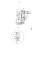
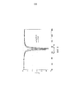
- фиг. 1 - вид в разрезе модуля отслеживания согласно варианту осуществления изобретения;- FIG. 1 is a sectional view of a tracking module according to an embodiment of the invention;
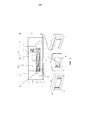
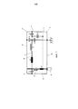
- фиг. 2 - вид четырех разных моделей металлической полости;- FIG. 2 is a view of four different models of a metal cavity;
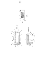
- фиг. 3A-3B - вид сбоку антенны PIFA;- FIG. 3A-3B is a side view of a PIFA antenna;
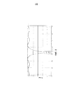
- фиг. 4 - вид сверху антенны PIFA;- FIG. 4 is a top view of a PIFA antenna;
- фиг. 5 - график, показывающий коэффициент отражения в зависимости от частоты антенны PIFA, расположенной в металлической полости;- FIG. 5 is a graph showing a reflection coefficient as a function of the frequency of a PIFA antenna located in a metal cavity;
- фиг. 6 - два графика, демонстрирующие коэффициент отражения в зависимости от частоты антенны PIFA, расположенной в металлической полости, с защитной крышкой выполненной из ПЭНП (полиэтилена низкой плотности) или без нее, и- FIG. 6 is two graphs showing a reflection coefficient depending on the frequency of a PIFA antenna located in a metal cavity, with or without a protective cover made of LDPE (low density polyethylene), and
- фиг. 7 - электрическая схема антенны PIFA согласно варианту осуществления этого изобретения.- FIG. 7 is a circuit diagram of a PIFA antenna according to an embodiment of this invention.
[0019] Для большей ясности, аналогичные или идентичные элементы обозначены одинаковыми ссылочными позициями на всех фигурах.[0019] For clarity, similar or identical elements are denoted by the same reference numerals in all figures.
ПОДРОБНОЕ ОПИСАНИЕ ВАРИАНТА ОСУЩЕСТВЛЕНИЯDETAILED DESCRIPTION OF EMBODIMENT
[0020] Это изобретение включает в себя все технические характеристики модуля 1 отслеживания контактной направляющей детали, описанного во французских патентных заявках №№ FR1155993, FR1155994 и FR1155995.[0020] This invention includes all the technical characteristics of the contact
[0021] В этом варианте осуществления изобретения, рассматриваемой контактной направляющей деталью является подшипник, заключенный в корпус роликового подшипника, заключенный в буксу вагонной оси, но этот конкретный вариант осуществления не обязательно носит ограничительный характер.[0021] In this embodiment, the contact guide part in question is a bearing enclosed in a roller bearing housing enclosed in an axle box, but this particular embodiment is not necessarily restrictive.
[0022] На фиг. 1 показан модуль 1 отслеживания, по меньшей мере, одной физической амплитудной характеристики контактной направляющей детали, например, подшипника, заключенного в корпус подшипника, состоящий из нескольких технологических сборочных блоков, описанных во французских патентных заявках №№ FR1155993, FR1155994 и FR1155995, и, в частности, блока для передачи диагностики состояния подшипника.[0022] FIG. 1 shows a
[0023] Этот блок для передачи диагностики состояния подшипника заключает в себе всю техническую структуру, позволяющую интегрировать передающую антенну в модуль отслеживания и подключать его к электронному модулю передачи (беспроводным узлам датчиков) через радиочастоту с низким потреблением.[0023] This block for transmitting diagnostics of the condition of the bearing comprises the entire technical structure that allows integrating the transmitting antenna into the tracking module and connecting it to the electronic transmission module (wireless sensor nodes) through the low-frequency radio frequency.
[0024] Этот модуль 1 отслеживания содержит антенну 5 PIFA, содержащуюся в металлической полости 2, обращенной наружу и закрытой защитной крышкой 4 из прозрачного материала, пропускающего электромагнитные волны, по меньшей мере, в частотном диапазоне, соответствующем максимальному коэффициенту усиления антенны 5 PIFA (планарной инвертированной F-антенны).[0024] This
[0025] Благодаря этой защитной крышке 4 антенна 5 PIFA защищена, в частности, если модуль отслеживания располагается в опасной среде, например вагонной тележке.[0025] Thanks to this
Эта защитная крышка 4 антенны 5 PIFA состоит из материала типа ПЭ (полиэтилена), и имеет толщину по меньшей мере 3 мм.This
В частности, этот материал является, например, ПЭНП (полиэтилен низкой плотности), относительная диэлектрическая проницаемость которого εr=2,10 и коэффициент диэлектрических потерь tanδ=1,7⋅10-3 для частоты 869 МГц.In particular, this material is, for example, LDPE (low density polyethylene), whose relative permittivity ε r = 2.10 and dielectric loss coefficient tanδ = 1.7an10 -3 for a frequency of 869 MHz.
Преимущество ПЭ как высокой (ВП), так и низкой (НП) плотности состоит в его хорошей деформационной характеристике без ухудшения под действием удара. Кроме того, ПЭ имеет очень хорошие электромагнитные свойства на частоте 868 МГц. Хотя, напротив, полимеры типа Plexiglas "зарегистрированный товарный знак", армированные стекловолокном, хрупки и разбиваются под действием удара.The advantage of PE of both high (VP) and low (NP) density is its good deformation characteristic without deterioration by impact. In addition, PE has very good electromagnetic properties at a frequency of 868 MHz. Although, on the contrary, Plexiglas type "registered trademark" polymers reinforced with fiberglass are brittle and break under impact.
Альтернативно, материалом, содержащим защитную крышку 4 антенны 5 PIFA, может быть ПЭВП, более жесткий, чем ПЭНП, и, кроме того, имеющий очень хорошие диэлектрические характеристики.Alternatively, the material containing the
[0026] Металлическая полость 2 располагается в части этого модуля отслеживания. Эта часть может относиться, например, к крышке или теплоотводу.[0026] The
[0027] В этом варианте осуществления эта часть относится, без ограничения, к теплоотводу 3 с ребрами из алюминиевого сплава.[0027] In this embodiment, this part relates, without limitation, to the heat sink 3 with aluminum alloy fins.
[0028] В случае, когда эта часть относится к теплоотводу 3, антенна PIFA этого модуля 1 отслеживания специально адаптирована к массе металла, образованной этим теплоотводом 3.[0028] In the case where this part relates to the heat sink 3, the PIFA antenna of this
Кроме того, интеграция антенны 5 PIFA в металлическую полость 2 является оптимальной интеграцией, поскольку она осуществляется в верхней части, теплоотводе 3, и поэтому верхняя часть, которая отделена от крышки буксы оси, потенциального источника расстройки антенны.In addition, the integration of the
Кроме того, заметим, что в металлической полости антенна 5 PIFA защищена от внешней среды, тем не менее, сохраняя способность оптимального излучения на приемник, например, радиочастотный терминал, расположенный на стороне дороги, находящейся на сравнительно небольшом расстоянии, около десяти метров.In addition, we note that in the metal cavity, the 5 PIFA antenna is protected from the external environment, however, while maintaining the ability of optimal radiation to the receiver, for example, a radio frequency terminal located on the side of the road at a relatively short distance, about ten meters.
[0029] На фиг. 2 показаны интеграция и крепление антенны PIFA в металлической полости 2 с использованием представления четырех разных моделей 11, 12, 13, 14 этой металлической полости 2.[0029] FIG. 2 shows the integration and mounting of the PIFA antenna in the
[0030] Конкретные конфигурации осуществляются в металлической полости 2 для обеспечения оптимального крепления антенны 5 PIFA, поскольку, согласно ее расположению в металлической полости, антенна 5 PIFA не излучает одинаково.[0030] Specific configurations are implemented in the
[0031] Для крепления антенны 5 PIFA в металлической полости 2, предусмотрена металлическая опора 6, содержащая центральное приспособление 9.[0031] To mount the
[0032] Это центральное приспособление 9 предназначено принимать соединители 10, когда, в ходе установки антенны 5, антенна 5 PIFA размещается и затем скользит в металлическую полость 2, пока участок плоскости 20 заземления не придет в контакт с металлической опорой 6, и боковая сторона антенны 5 PIFA, соседствующая с этой плоскостью 20 заземления, не расположится напротив угла 8 и без контакта с этим углом 8 металлической полости 2. После этого антенна PIFA прикрепляется непосредственно к задней опоре, например, с использованием крепежного средства, например, клея.[0032] This
Кроме того, следует понимать, что центральное приспособление 9 необходимо, в частности, для соединения кабеля для ограничения крутящих усилий на соединителях.In addition, it should be understood that the
[0033] С другой стороны, механизм снабжения содержит переменный конденсатор, что позволяет оптимизировать настройку антенны PIFA на нужную частоту в ходе установки антенны PIFA в металлическую полость.[0033] On the other hand, the supply mechanism includes a variable capacitor, which allows you to optimize the tuning of the PIFA antenna to the desired frequency during installation of the PIFA antenna in a metal cavity.
[0034] Этот переменный конденсатор (варикап) параллельно подключен к антенне 5, между центральной жилой соединителя 10 и плоскостью заземления.[0034] This variable capacitor (varicap) is connected in parallel to the
[0035] Переменный конденсатор позволяет, с учетом точности расположения в такой полости, что непосредственно влияет на качество настройки в ходе установки антенны, регулировать эту антенну 5 PIFA по частоте для достижения оптимального коэффициента усиления при передаче на нужной частоте: 868 МГц.[0035] The variable capacitor allows, taking into account the accuracy of the location in such a cavity, which directly affects the quality of tuning during installation of the antenna, to adjust this 5 PIFA antenna in frequency to achieve the optimal gain when transmitting at the desired frequency: 868 MHz.
[0036] На фиг. 3A, 3B и 7 показан вид сбоку антенны 5 PIFA, и на фиг. 4 показан вид сверху этой антенны 5.[0036] FIG. 3A, 3B, and 7 show a side view of the
[0037] Эта антенна PIFA содержит планарный прямоугольный излучающий элемент 21 и плоскость заземления, которая сложена вокруг излучающего элемента для уменьшения физического размера антенны 5.[0037] This PIFA antenna comprises a planar
[0038] Согласно варианту осуществления плоскость заземления имеет электрическую длину, которая выбирается для обеспечения резонанса на частоте 868 МГц. Эта плоскость заземления состоит из первого участка 20, левого бокового участка 19, сложенного участка над излучающим элементом 22, правого бокового участка 27 и возврата плоскости заземления, реализованного участком 17.[0038] According to an embodiment, the ground plane has an electrical length that is selected to provide resonance at a frequency of 868 MHz. This ground plane consists of a
[0039] Этот излучающий элемент 21 подключен к разным участкам 20, 19, 22, 27 и 17, которые образуют эту повернутую плоскость заземления, следующими конденсаторами:[0039] This radiating
- C1 между секцией линии 24 питания и участком боковой плоскости 19 заземления. Этот конденсатор вносит свой вклад, в первой степени, в электрический импеданс антенны (50 Ом);- C1 between the section of the
- C2 между излучающим элементом 21 и участком боковой плоскости заземления 27;- C2 between the radiating
- C3 между излучающим элементом 21 и участком относительно возврата плоскости заземления 17;- C3 between the radiating
- C4 между излучающим элементом 21 и участком плоскости заземления 22, и- C4 between the radiating
- C5 между излучающим элементом 21 и участком плоскости 20 заземления.- C5 between the radiating
[0040] Этот излучающий элемент 21 располагается над участком плоскости 20 заземления и подключен к механизму снабжения, состоящему из линии 24 питания и соединителя 10.[0040] This radiating
[0041] Согласно фиг. 7 линия 24 питания и излучающий элемент 21 образуют "плюсовой" полюс этой антенны PIFA и представлены двумя катушками L1 и L2 индуктивности и двумя последовательно соединенными резисторами rc1 и rc2.[0041] Referring to FIG. 7, the
[0042] Эти резисторы rc1 и rc2 позволяют регулировать потери, обусловленные эффектом Джоуля вследствие природы проводника, который, в этом неограничительном варианте осуществления, выполнен из меди.[0042] These resistors rc1 and rc2 make it possible to control losses due to the Joule effect due to the nature of the conductor, which, in this non-limiting embodiment, is made of copper.
[0043] Катушки L1 и L2 индуктивности демонстрируют индукционный эффект компонентов излучающего элемента 21 и линии 24 питания, и вносят свой вклад в импеданс, "наблюдаемый" соединителем 10.[0043] Inductors L1 and L2 demonstrate the induction effect of the components of the radiating
[0044] Механизм снабжения соответствует модулю радиопередачи, который позволяет передавать информацию, поступающую от модуля отслеживания.[0044] The supply mechanism corresponds to a radio transmission module that allows information from a tracking module to be transmitted.
[0045] Первый конец секции линии 24 питания приходит из центральной жилы соединителя 10, например, типа SMA, и второй конец входит в круглую полость 28 линейной секции 22 плоскости заземления при минимальном круговом расстоянии около 1 мм. Эта роль секции линии 24 питания состоит в механической поддержке излучающего элемента 21.[0045] The first end of the section of the
[0046] Плоскость заземления включает в себя сложенный участок 22 параллельный участку плоскости 20 заземления, таким образом, чтобы уменьшить размер антенны 5 PIFA, одновременно сохраняя ту же самую электрическую длину. Эта электрическая длина выбирается для обеспечения резонанса антенны на частоте 868 МГц.[0046] The ground plane includes a folded
[0047] Этот параллельный участок 22 оказывает емкостной эффект на входной импеданс антенны 5 PIFA, и вносит свой вклад совместно с индуктивностью L1 и L2 во входной импеданс, наблюдаемый соединителем 10.[0047] This
[0048] Сложенный участок 22 содержит возврат плоскости заземления, соответствующий секции линии 17. Длина этой секции линии 17 является переменной регулировки для настройки антенны 5 PIFA по частоте т.е. центрирования радиочастоты на 868 МГц и минимальной амплитуде коэффициента S11 отражения этой антенны PIFA.[0048] The folded
Эта переменная является главной переменной регулировки, которая позволяет точно регулировать антенну 5. Задача состоит в том, чтобы обеспечить электрический импеданс 50 Ом и минимизировать значение коэффициента S11 отражения до нужной частоты (868 МГц). Следовательно, коэффициент передачи достигает максимума.This variable is the main adjustment variable that allows you to fine-tune the
[0049] Принцип работы антенны таков: электрическая мощность излучающего элемента приводит к возникновению электрических токов в этом элементе, которые, посредством индуктивной и емкостной связи со сложенной плоскостью заземления и индукционного эффекта, приводит к возбуждению поверхностных токов этой плоскости заземления. Излучение этой антенны является полусферическим на стороне A, но также на стороне B (но с меньшей амплитудой). Эта антенна излучает, в основном, в сторону A (расположенную напротив защитной стенки), но также через свою конструкцию назад (в сторону B).[0049] The principle of operation of the antenna is as follows: the electric power of the radiating element leads to the appearance of electric currents in this element, which, through inductive and capacitive coupling with the folded ground plane and the induction effect, leads to the excitation of surface currents of this ground plane. The radiation from this antenna is hemispherical on side A, but also on side B (but with a lower amplitude). This antenna radiates mainly towards A (located opposite the protective wall), but also through its structure back (towards B).
[0050] Заметим, что изменение параметров, которые определяют размеры антенны PIFA, позволяют оптимально конфигурировать ее.[0050] Note that changing the parameters that determine the size of the PIFA antenna allows you to optimally configure it.
[0051] Как таковые, три из этих параметров, определяющие размеры антенны PIFA, показаны на фиг. 3A и имеют следующие характеристики:[0051] As such, three of these parameters defining the dimensions of the PIFA antenna are shown in FIG. 3A and have the following characteristics:
- параметр 25, он соответствует расстоянию между линией питания и боковой поверхностью плоскости 19 заземления. Это расстояние определяет, в первой степени, входной импеданс антенны. Для адаптации, он должен составлять 50 Ом;-
- параметр 26, он соответствует расстоянию между излучающим элементом 21 и участком 27 плоскости заземления. Это расстояние также вносит вклад во входной импеданс антенны, но оказывает меньшее влияние, чем параметр 25.-
- параметр 23, он соответствует длине участка 17 плоскости заземления. Эта длина составляет главную переменную регулировки, которая позволяет точно регулировать антенну по частоте. Задача, предпочтительно, состоит в получении электрического импеданса 50 Ом и минимизации значения коэффициента S11 отражения до нужной частоты (868 МГц). Следовательно, коэффициент пропускания достигает максимума.-
[0052] Излучающий элемент 21 содержится в подложке, содержащей несколько слоев 15, 16 разных материалов. Этот излучающий элемент 21 относится к меди, толщина которой равна 35 мкм.[0052] The radiating
[0053] В частности, эта подложка состоит из слоя 16 первого материала толщиной 3,2 мм между двумя слоями 15 второго материала толщиной 800 мкм каждый.[0053] In particular, this substrate consists of a
[0054] В уровне техники известно, что антенна PIFA не содержит материала, отличного от металла, и подложки, образованной воздухом.[0054] It is known in the art that a PIFA antenna does not contain material other than metal and a substrate formed by air.
[0055] Использование, в контексте этого изобретения, материалов, отличных от воздуха, электромагнитными характеристиками которых являются диэлектрическая проницаемость εr и магнитная проницаемость μr, позволяют уменьшить физический размер антенны.[0055] Using, in the context of this invention, non-air materials whose electromagnetic characteristics are permittivity ε r and permittivity μ r , the physical size of the antenna can be reduced.
[0056] Подложка, согласно изобретению, содержит стопку, по меньшей мере, двух диэлектрических материалов, различной толщины и с разными комплексными значениями диэлектрической проницаемости на частоте 868 МГц.[0056] The substrate according to the invention contains a stack of at least two dielectric materials of different thicknesses and with different complex values of the dielectric constant at a frequency of 868 MHz.
[0057] Согласно варианту осуществления изобретения первый материал принадлежит семейству ПЭВП (полиэтилена высокой плотности), и второй материал принадлежит семейству ПТФЭ (политетрафторэтилена).[0057] According to an embodiment of the invention, the first material belongs to the HDPE (high density polyethylene) family, and the second material belongs to the PTFE (polytetrafluoroethylene) family.
В этом варианте осуществления, первым материалом является инертный пластик, и второй материал соответствует Arlon "зарегистрированный товарный знак" 25N.In this embodiment, the first material is inert plastic, and the second material corresponds to Arlon "registered trademark" 25N.
ПЭВП имеет относительную диэлектрическую проницаемость εr=2,16, и коэффициент диэлектрических потерь tanδ=1⋅10-3 на частоте 868 МГц.HDPE has a relative permittivity ε r = 2.16, and the dielectric loss coefficient tanδ = 1⋅10 -3 at a frequency of 868 MHz.
[0058] Этот подбор материалов является очень хорошим компромиссом в отношении стоимости и доступности материалов.[0058] This selection of materials is a very good compromise regarding the cost and availability of materials.
[0059] Преимущество, связанное с использованием такой подложки, содержащей несколько слоев 15, 16 разных материалов, связано с тем фактом, что это позволяет уменьшить физический размер антенны. Кроме того, другое преимущество этой подложки дополнительно относится к тому факту, что она обеспечивает оптимальное механическое сопротивление излучающего элемента на регулируемом расстоянии от плоскости заземления.[0059] The advantage associated with the use of such a substrate containing
[0060] Заметим, в частности, что другое определение размеров этой антенны 5 PIFA также возможно благодаря использованию подложки, состоящей из 100% Arlon "зарегистрированный товарный знак" или 100% PEHB.[0060] Note, in particular, that another sizing of this 5 PIFA antenna is also possible by using a substrate consisting of 100% Arlon "registered trademark" or 100% PEHB.
[0061] Кроме того, оба таких материала, используемых в подложке, имеют очень хорошие электромагнитные характеристики на частоте 868 МГц (желаемых рабочих частотах антенны): с потерями менее 5⋅10-3.[0061] In addition, both of the material used in the substrate, have a very good electromagnetic characteristics at a frequency of 868 MHz (the desired antenna operating frequencies) losses less 5⋅10 -3.
[0062] Без ограничения, размеры антенны PIFA указаны в нижеприведенной таблице 1.[0062] Without limitation, the dimensions of the PIFA antenna are shown in Table 1 below.
В контексте создания этой антенны PIFA значения в этой таблице, относительно характеристик этой антенны, могут изменяться согласно производственному допуску, который может составлять до нескольких десятков миллиметров.In the context of creating this PIFA antenna, the values in this table, relative to the characteristics of this antenna, can vary according to the manufacturing tolerance, which can be up to several tens of millimeters.
[0063] Соединители 10 антенны 5 PIFA позволяют подключать ее к механизму снабжения и к электронному модулю передачи (беспроводным узлам датчиков).[0063]
[0064] Это соответствует соединителю 10 адаптированному к 50 Ом, который может относиться к типу SMA 10 (акроним SubMiniature version A (субминиатюрная версия А)), UMP 10 или UFL 10.[0064] This corresponds to a connector adapted to 50
[0065] В этом варианте осуществления соединители 10 антенны PIFA относятся к низкопрофильным соединителям, а следовательно, к типу UMP или UFL. Такие соединители позволяют получить улучшенную интеграцию антенны 5 PIFA в металлическую полость 2 благодаря их малому размеру.[0065] In this embodiment, the
[0066] Преимущество этой антенны 5 PIFA в том, что она имеет всенаправленные свойства со значениями коэффициента усиления, достаточными для обеспечения адекватной производительности с распространениями внутрь металлической полости, с учетом значений выходной мощности и чувствительности в приеме устройств радиосвязи малой дальности.[0066] The advantage of this
[0067] Как таковая, антенна 5 PIFA имеет возможность принимать вертикально, а также горизонтально поляризованные электромагнитные волны, что является весомым преимуществом во внутренних средах, где деполяризация является преобладающим явлением, и выбор поляризации затруднен, что может иметь место в металлической полости 2.[0067] As such, the
[0068] Согласно фиг. 5 антенна 5 PIFA, прикрепленная к металлической полости 2, имеет максимальный коэффициент усиления на резонансной частоте 868 МГц, с полосой 8 МГц. В случае необходимости, резонансную частоту можно увеличить для смещения использования защитной крышки 4.[0068] Referring to FIG. 5
[0069] Как таковая, фиг. 6 показывает влияние защитной крышки 4, выполненной из ПЭНП толщиной 3,2 мм, расположенной напротив передающей антенны PIFA, прикрепленной к внутренней поверхности металлической полости 2. Таким образом, эта антенна PIFA излучает на частоте 868 МГц.[0069] As such, FIG. 6 shows the effect of a
[0070] Таким образом, следует понимать, что эту резонансную частоту можно смещать, добавляя диэлектрический материал напротив антенны PIFA (5).[0070] Thus, it should be understood that this resonant frequency can be biased by adding dielectric material opposite the PIFA antenna (5).
[0071] Например, добавление 3 мм FR4 с относительной диэлектрической проницаемостью εr=4,5, на переднюю поверхность защитной крышки ПЭНП приводит к сдвигу частоты, т.е. изменению частоты излучения от 878 МГц до 868 МГц.[0071] For example, the addition of 3 mm FR4 with a relative permittivity ε r = 4.5 onto the front surface of the LDPE protective cover results in a frequency shift, i.e. a change in the radiation frequency from 878 MHz to 868 MHz.
[0072] Аналогичный результат можно получить, выбирая защитную крышку с диэлектрической проницаемостью, которая выше, чем у текущего ПЭНП, или более существенную толщину защиты.[0072] A similar result can be obtained by choosing a protective cover with a dielectric constant that is higher than that of the current LDPE, or a more significant thickness of the protection.
[0073] Аналогично, эффекты, способные изменять полосу, можно получить, изменяя толщину антенны 5 PIFA.[0073] Similarly, effects capable of changing the band can be obtained by changing the thickness of the 5 PIFA antenna.
[0074] Эта антенна PIFA собирается согласно следующим этапам:[0074] This PIFA antenna is assembled according to the following steps:
- нанесение проводящих материалов на подложку 15, 16, относящихся к участкам плоскости 20 и 22 заземления плоскости заземления на горизонтальных боковых поверхностях;- the application of conductive materials to the
- сверление материалов 15 и 16 подложки, позволяющее реализовать линии 24 до металлизации;- drilling of
- формирование стопки разных слоев материалов подложки;- the formation of a stack of different layers of substrate materials;
- плакирование и прессование проводящих материалов, образующих плоскости заземления и излучающий элемент, на вертикальных боковых поверхностях антенны PIFA, и- cladding and pressing of conductive materials forming the ground plane and the radiating element on the vertical side surfaces of the PIFA antenna, and
- металлизация просверленного отверстия подложки, что позволяет реализовать линию 24, и- metallization of the drilled holes of the substrate, which allows the implementation of
- приваривание соединителя 10 к секции линии 20 плоскости заземления.- welding of the
[0075] В этом варианте осуществления этого изобретения регулировку антенны по частоте можно осуществлять итерационно с использованием этапов измерения частоты антенны в полости и коррекции, осуществляемой варикапом.[0075] In this embodiment of this invention, the frequency adjustment of the antenna can be iterated using the steps of measuring the frequency of the antenna in the cavity and the correction performed by the varicap.
Claims (24)
Applications Claiming Priority (2)
| Application Number | Priority Date | Filing Date | Title |
|---|---|---|---|
| FR1156015 | 2011-07-04 | ||
| FR1156015A FR2977732B1 (en) | 2011-07-04 | 2011-07-04 | MONITORING MODULE OF AT LEAST ONE PHYSICAL SIZE CHARACTERISTIC OF THE STATE OF A CONTACT GUIDING ORGAN COMPRISING A PIFA ANTENNA |
Publications (2)
| Publication Number | Publication Date |
|---|---|
| RU2012127584A RU2012127584A (en) | 2014-01-10 |
| RU2613001C2 true RU2613001C2 (en) | 2017-03-14 |
Family
ID=46317287
Family Applications (1)
| Application Number | Title | Priority Date | Filing Date |
|---|---|---|---|
| RU2012127584A RU2613001C2 (en) | 2011-07-04 | 2012-07-02 | Module for monitoring at least one physical amplitude characteristic of state of contact guide part comprising pifa antenna |
Country Status (6)
| Country | Link |
|---|---|
| EP (1) | EP2544303B1 (en) |
| JP (1) | JP6125165B2 (en) |
| KR (1) | KR20150127837A (en) |
| CN (1) | CN102866012A (en) |
| FR (1) | FR2977732B1 (en) |
| RU (1) | RU2613001C2 (en) |
Families Citing this family (4)
| Publication number | Priority date | Publication date | Assignee | Title |
|---|---|---|---|---|
| CN104995075B (en) * | 2012-11-30 | 2017-09-12 | 前进铁轨检测与信息系统有限公司 | Cap assemblies for hot repacking examining system |
| CN104635640A (en) * | 2013-11-12 | 2015-05-20 | 宁夏巨能机器人系统有限公司 | Informatization production management system of equipment for machining before bearing grinding |
| JP2022048420A (en) * | 2020-09-15 | 2022-03-28 | Ntn株式会社 | Bearing device |
| RU2745168C1 (en) * | 2020-10-02 | 2021-03-22 | Общество с ограниченной ответственностью Научно-производственное предприятие "РаТорм" | Freight car monitoring and diagnostics device |
Citations (9)
| Publication number | Priority date | Publication date | Assignee | Title |
|---|---|---|---|---|
| US5226736A (en) * | 1991-08-30 | 1993-07-13 | Hoesch Ag | Device for monitoring antifriction bearings |
| US20030020655A1 (en) * | 2001-07-26 | 2003-01-30 | Mckinzie William E. | Reduced weight artificial dielectric antennas and method for providing the same |
| JP2003227526A (en) * | 2002-02-05 | 2003-08-15 | Nsk Ltd | Bearing with sensor |
| JP2003307228A (en) * | 2002-04-12 | 2003-10-31 | Nsk Ltd | Bearing device with sensor |
| JP2006258242A (en) * | 2005-03-18 | 2006-09-28 | Ntn Corp | Bearing with antenna |
| DE102007056150A1 (en) * | 2007-11-16 | 2009-05-20 | Micropelt Gmbh | Energy-self-sufficient sensor system for determining e.g. temperature, to detect condition of liquid, in transmissions of road vehicle, has carrier element inserted in opening of element such that measuring variable is determined by sensor |
| WO2010029306A1 (en) * | 2008-09-12 | 2010-03-18 | The University Of Birmingham | Multifunctional antenna |
| RU2386197C1 (en) * | 2006-03-28 | 2010-04-10 | Квэлкомм Инкорпорейтед | Modified inverted f-antenna for wireless communication |
| JP2010112387A (en) * | 2008-11-04 | 2010-05-20 | Jtekt Corp | Rolling bearing unit with sensor |
Family Cites Families (7)
| Publication number | Priority date | Publication date | Assignee | Title |
|---|---|---|---|---|
| FR1155993A (en) | 1956-07-12 | 1958-05-12 | Male Fosse & Fils | Improvements to machines for making biscuits |
| FR1155994A (en) | 1956-07-12 | 1958-05-12 | Fabrication De Tubes En Matier | Sophisticated plastic pipe support device |
| FR1155995A (en) | 1956-07-13 | 1958-05-12 | J Souvignet & Fils Ets | Moped rear suspension and its manufacturing process |
| US6535135B1 (en) * | 2000-06-23 | 2003-03-18 | The Timken Company | Bearing with wireless self-powered sensor unit |
| US6819292B2 (en) * | 2001-03-09 | 2004-11-16 | Arad Measuring Technologies Ltd | Meter register |
| US7034711B2 (en) * | 2001-08-07 | 2006-04-25 | Nsk Ltd. | Wireless sensor, rolling bearing with sensor, management apparatus and monitoring system |
| US7034768B2 (en) * | 2003-09-24 | 2006-04-25 | Gas Technology Institute | Antenna system |
-
2011
- 2011-07-04 FR FR1156015A patent/FR2977732B1/en active Active
-
2012
- 2012-06-22 KR KR1020120067368A patent/KR20150127837A/en not_active Application Discontinuation
- 2012-06-27 EP EP12173786.0A patent/EP2544303B1/en not_active Not-in-force
- 2012-07-02 RU RU2012127584A patent/RU2613001C2/en not_active IP Right Cessation
- 2012-07-03 JP JP2012149517A patent/JP6125165B2/en active Active
- 2012-07-04 CN CN2012102311364A patent/CN102866012A/en active Pending
Patent Citations (9)
| Publication number | Priority date | Publication date | Assignee | Title |
|---|---|---|---|---|
| US5226736A (en) * | 1991-08-30 | 1993-07-13 | Hoesch Ag | Device for monitoring antifriction bearings |
| US20030020655A1 (en) * | 2001-07-26 | 2003-01-30 | Mckinzie William E. | Reduced weight artificial dielectric antennas and method for providing the same |
| JP2003227526A (en) * | 2002-02-05 | 2003-08-15 | Nsk Ltd | Bearing with sensor |
| JP2003307228A (en) * | 2002-04-12 | 2003-10-31 | Nsk Ltd | Bearing device with sensor |
| JP2006258242A (en) * | 2005-03-18 | 2006-09-28 | Ntn Corp | Bearing with antenna |
| RU2386197C1 (en) * | 2006-03-28 | 2010-04-10 | Квэлкомм Инкорпорейтед | Modified inverted f-antenna for wireless communication |
| DE102007056150A1 (en) * | 2007-11-16 | 2009-05-20 | Micropelt Gmbh | Energy-self-sufficient sensor system for determining e.g. temperature, to detect condition of liquid, in transmissions of road vehicle, has carrier element inserted in opening of element such that measuring variable is determined by sensor |
| WO2010029306A1 (en) * | 2008-09-12 | 2010-03-18 | The University Of Birmingham | Multifunctional antenna |
| JP2010112387A (en) * | 2008-11-04 | 2010-05-20 | Jtekt Corp | Rolling bearing unit with sensor |
Also Published As
| Publication number | Publication date |
|---|---|
| EP2544303B1 (en) | 2017-02-08 |
| CN102866012A (en) | 2013-01-09 |
| EP2544303A1 (en) | 2013-01-09 |
| JP6125165B2 (en) | 2017-05-10 |
| RU2012127584A (en) | 2014-01-10 |
| FR2977732A1 (en) | 2013-01-11 |
| KR20150127837A (en) | 2015-11-18 |
| FR2977732B1 (en) | 2016-07-01 |
| JP2013017177A (en) | 2013-01-24 |
Similar Documents
| Publication | Publication Date | Title |
|---|---|---|
| US9496596B2 (en) | Dielectric structure for antennas in RF applications | |
| KR102440191B1 (en) | Antenna with frequency selective element | |
| CN1233066C (en) | Antenna | |
| US20120313823A1 (en) | Ruggedized antenna system and method | |
| RU2613001C2 (en) | Module for monitoring at least one physical amplitude characteristic of state of contact guide part comprising pifa antenna | |
| US20130063316A1 (en) | Compacted patch antenna | |
| CA2968003C (en) | Broadband antenna in the crash pad for vehicle | |
| US7495629B2 (en) | Surface mountable inverted-F antenna and associated methods | |
| CN106329096B (en) | NFC antenna | |
| US20150009093A1 (en) | Antenna apparatus and portable wireless device equipped with the same | |
| KR20090061585A (en) | Antenna device | |
| US9524602B2 (en) | Compact antenna structure with a coupling device | |
| GB2289163A (en) | Antenna comprising a closed loop and a ground plane | |
| JP2018007108A (en) | Antenna device | |
| JP4636234B2 (en) | Wireless sensor transmission device and wireless sensor device | |
| Amer et al. | A Wide-Angle, Polarization-Insensitive, Wideband Metamaterial Absorber with Lumped Resistor Loading for ISM Band Applications | |
| AU2011254543B2 (en) | Compacted patch antenna | |
| FR3073094A1 (en) | PARAMETER MEASUREMENT SYSTEM OF A MONTE ASSEMBLY | |
| WO2024005642A1 (en) | Line sensor comprising a capacitive divider with integrated slot antenna | |
| CN116956983A (en) | Humidity sensing chipless radio frequency identification electronic tag device resistant to environmental interference | |
| JP2005204133A (en) | Transmitter |
Legal Events
| Date | Code | Title | Description |
|---|---|---|---|
| MM4A | The patent is invalid due to non-payment of fees |
Effective date: 20180703 |