RU2607922C2 - Electric device for leakage current limitation in medical devices, connected to patient, operating from accumulator batteries - Google Patents
Electric device for leakage current limitation in medical devices, connected to patient, operating from accumulator batteries Download PDFInfo
- Publication number
- RU2607922C2 RU2607922C2 RU2013141917A RU2013141917A RU2607922C2 RU 2607922 C2 RU2607922 C2 RU 2607922C2 RU 2013141917 A RU2013141917 A RU 2013141917A RU 2013141917 A RU2013141917 A RU 2013141917A RU 2607922 C2 RU2607922 C2 RU 2607922C2
- Authority
- RU
- Russia
- Prior art keywords
- switching device
- patient
- input voltage
- switching
- battery compartment
- Prior art date
Links
Images
Classifications
-
- H—ELECTRICITY
- H02—GENERATION; CONVERSION OR DISTRIBUTION OF ELECTRIC POWER
- H02H—EMERGENCY PROTECTIVE CIRCUIT ARRANGEMENTS
- H02H11/00—Emergency protective circuit arrangements for preventing the switching-on in case an undesired electric working condition might result
-
- A—HUMAN NECESSITIES
- A61—MEDICAL OR VETERINARY SCIENCE; HYGIENE
- A61N—ELECTROTHERAPY; MAGNETOTHERAPY; RADIATION THERAPY; ULTRASOUND THERAPY
- A61N1/00—Electrotherapy; Circuits therefor
- A61N1/18—Applying electric currents by contact electrodes
- A61N1/32—Applying electric currents by contact electrodes alternating or intermittent currents
- A61N1/38—Applying electric currents by contact electrodes alternating or intermittent currents for producing shock effects
- A61N1/39—Heart defibrillators
- A61N1/3925—Monitoring; Protecting
- A61N1/3931—Protecting, e.g. back-up systems
-
- A—HUMAN NECESSITIES
- A61—MEDICAL OR VETERINARY SCIENCE; HYGIENE
- A61B—DIAGNOSIS; SURGERY; IDENTIFICATION
- A61B5/00—Measuring for diagnostic purposes; Identification of persons
- A61B5/24—Detecting, measuring or recording bioelectric or biomagnetic signals of the body or parts thereof
- A61B5/30—Input circuits therefor
- A61B5/304—Switching circuits
-
- A—HUMAN NECESSITIES
- A61—MEDICAL OR VETERINARY SCIENCE; HYGIENE
- A61N—ELECTROTHERAPY; MAGNETOTHERAPY; RADIATION THERAPY; ULTRASOUND THERAPY
- A61N1/00—Electrotherapy; Circuits therefor
- A61N1/18—Applying electric currents by contact electrodes
- A61N1/32—Applying electric currents by contact electrodes alternating or intermittent currents
- A61N1/36—Applying electric currents by contact electrodes alternating or intermittent currents for stimulation
- A61N1/362—Heart stimulators
-
- H—ELECTRICITY
- H01—ELECTRIC ELEMENTS
- H01H—ELECTRIC SWITCHES; RELAYS; SELECTORS; EMERGENCY PROTECTIVE DEVICES
- H01H11/00—Apparatus or processes specially adapted for the manufacture of electric switches
-
- H—ELECTRICITY
- H02—GENERATION; CONVERSION OR DISTRIBUTION OF ELECTRIC POWER
- H02H—EMERGENCY PROTECTIVE CIRCUIT ARRANGEMENTS
- H02H5/00—Emergency protective circuit arrangements for automatic disconnection directly responsive to an undesired change from normal non-electric working conditions with or without subsequent reconnection
- H02H5/12—Emergency protective circuit arrangements for automatic disconnection directly responsive to an undesired change from normal non-electric working conditions with or without subsequent reconnection responsive to undesired approach to, or touching of, live parts by living beings
-
- A—HUMAN NECESSITIES
- A61—MEDICAL OR VETERINARY SCIENCE; HYGIENE
- A61B—DIAGNOSIS; SURGERY; IDENTIFICATION
- A61B2560/00—Constructional details of operational features of apparatus; Accessories for medical measuring apparatus
- A61B2560/02—Operational features
- A61B2560/0204—Operational features of power management
-
- Y—GENERAL TAGGING OF NEW TECHNOLOGICAL DEVELOPMENTS; GENERAL TAGGING OF CROSS-SECTIONAL TECHNOLOGIES SPANNING OVER SEVERAL SECTIONS OF THE IPC; TECHNICAL SUBJECTS COVERED BY FORMER USPC CROSS-REFERENCE ART COLLECTIONS [XRACs] AND DIGESTS
- Y02—TECHNOLOGIES OR APPLICATIONS FOR MITIGATION OR ADAPTATION AGAINST CLIMATE CHANGE
- Y02E—REDUCTION OF GREENHOUSE GAS [GHG] EMISSIONS, RELATED TO ENERGY GENERATION, TRANSMISSION OR DISTRIBUTION
- Y02E60/00—Enabling technologies; Technologies with a potential or indirect contribution to GHG emissions mitigation
- Y02E60/10—Energy storage using batteries
-
- Y—GENERAL TAGGING OF NEW TECHNOLOGICAL DEVELOPMENTS; GENERAL TAGGING OF CROSS-SECTIONAL TECHNOLOGIES SPANNING OVER SEVERAL SECTIONS OF THE IPC; TECHNICAL SUBJECTS COVERED BY FORMER USPC CROSS-REFERENCE ART COLLECTIONS [XRACs] AND DIGESTS
- Y10—TECHNICAL SUBJECTS COVERED BY FORMER USPC
- Y10T—TECHNICAL SUBJECTS COVERED BY FORMER US CLASSIFICATION
- Y10T29/00—Metal working
- Y10T29/49—Method of mechanical manufacture
- Y10T29/49002—Electrical device making
- Y10T29/49105—Switch making
Abstract
Description
ОБЛАСТЬ ТЕХНИКИFIELD OF TECHNOLOGY
Изобретение в целом относится к работающим от аккумуляторной батареи присоединенным к пациенту медицинским устройствам. Оно находит конкретное применение в связи с ограничением тока утечки для присоединенных к пациентам медицинских устройств и будет описано с конкретной ссылкой на них. Однако должно быть понятно, что оно также находит применение в других сценариях использования, и не обязательно ограничено вышеупомянутым применением.The invention generally relates to battery operated medical devices connected to a patient. It finds particular application in connection with limiting the leakage current for medical devices connected to patients and will be described with specific reference to them. However, it should be understood that it also finds use in other use cases, and is not necessarily limited to the aforementioned use.
ПРЕДШЕСТВУЮЩИЙ УРОВЕНЬ ТЕХНИКИBACKGROUND OF THE INVENTION
Присоединенные к пациенту медицинские устройства, как правило, должны удовлетворять стандартам безопасности, ограничивающим ток утечки на пациентах. Например, медицинские рынки по всему миру используют международный стандарт IEC 60601-1, редакция вторая, 1988-12, в качестве основы для аттестации медицинских продуктов. IEC 60601-1 требует, чтобы любой открытый рабочий компонент медицинского устройства был изолирован от соединения с пациентом и предписывает требуемый уровень изоляции. Например, 10 мкА являются ограничением на ток утечки пациента для приспособленных под сердечную функцию (CF) устройств. Ограничения на ток утечки важны, среди прочего, для пациентов с внутренними соединениями, когда импеданс кожи не ограничивает ток утечки, и пациентов с чувствительными медицинскими имплантатами, которые могут быть поддерживающими жизнь.Medical devices attached to a patient should generally meet safety standards that limit the leakage current of patients. For example, medical markets around the world use the international standard IEC 60601-1, second edition, 1988-12, as the basis for certification of medical products. IEC 60601-1 requires that any open operating component of a medical device be isolated from the patient connection and prescribe the required level of isolation. For example, 10 μA is a limitation on the patient leakage current for devices adapted to the cardiac function (CF). Limitations on leakage current are important, among other things, for patients with internal compounds, when the skin impedance does not limit the leakage current, and for patients with sensitive medical implants that can be life-supporting.
При замене аккумуляторных батарей в медицинском устройстве с источником питания, включающим в себя одну или более аккумуляторных батарей, клеммы присоединения аккумуляторных батарей для еще не установленных аккумуляторных батарей могут быть доступны и находиться под напряжением вследствие последовательного соединения уже установленных аккумуляторных батарей. Если пациент, присоединенный к медицинскому устройству, должен соприкасаться с одной из этих клемм присоединения аккумуляторных батарей, результирующий ток утечки может превышать границы безопасности. Единственными ограничениями на электрический ток были бы импеданс источника аккумуляторных батарей, импеданс пациента, импеданс побочных цепей и импеданс соединений пациента. Контакт с клеммой присоединения аккумуляторной батареи под напряжением мог бы возникать у пациента, прикасающегося к клемме присоединения аккумуляторной батареи, непосредственно или опосредованно, через ухаживающего, который меняет аккумуляторные батареи.When replacing batteries in a medical device with a power source including one or more batteries, the battery connection terminals for batteries not yet installed may be accessible and energized due to the series connection of already installed batteries. If a patient connected to a medical device must come into contact with one of these battery connection terminals, the resulting leakage current may exceed the safety limits. The only restrictions on electric current would be the impedance of the battery source, the impedance of the patient, the impedance of the side circuits, and the impedance of the patient connections. The contact with the battery connection terminal while energized could occur in a patient touching the battery connection terminal, directly or indirectly, through a carer who changes the batteries.
Для ограничения тока утечки пациента могло бы применяться механическое средство, препятствующее доступу к клеммам присоединения аккумуляторных батарей. Однако механические средства обременительны для пользователей и дорогостоящи для производства. Еще один способ ограничения тока утечки пациента состоит в том, чтобы увеличивать импеданс соединения пациента. Однако некоторые измерения показателей пациента, такие как дыхание, обязательно требуют низкого входного импеданса. Еще один потенциальный способ ограничения тока утечки пациента состоит в том, чтобы изолировать входы пациента гальваническими средствами, такими как трансформаторы и/или оптроны. Однако эти подходы дорогостоящи, энергозатратны и требуют драгоценного пространства. Они аннулируют главное преимущество небольшого легкого работающего от аккумуляторной батареи медицинского устройства.To limit the leakage current of the patient, mechanical means could be used to prevent access to the battery connection terminals. However, mechanical means are cumbersome for users and expensive to manufacture. Another way to limit the leakage current of a patient is to increase the impedance of the patient connection. However, some patient measurements, such as breathing, necessarily require low input impedance. Another potential way to limit the leakage current of a patient is to isolate the patient's inputs with galvanic means such as transformers and / or optocouplers. However, these approaches are costly, energy consuming and require precious space. They nullify the main advantage of a small, lightweight, battery-powered medical device.
КРАТКОЕ ИЗЛОЖЕНИЕ СУЩЕСТВА ИЗОБРЕТЕНИЯSUMMARY OF THE INVENTION
Настоящая заявка предлагает новые и улучшенные системы и способы, применяющие электрическое средство для преодоления упомянутых выше и других проблем.This application offers new and improved systems and methods that use an electrical means to overcome the above and other problems.
В соответствии с одним аспектом, предусмотрена система для электрического ограничения тока утечки в присоединенном к пациенту медицинском устройстве. Система включает в себя первый набор из одного или более переключающих устройств, которые избирательно соединяют первый выход питания батарейного отсека с первым входом электронных компонентов присоединенного к пациенту медицинского устройства на основании первой полярности входного напряжения батарейного отсека. Система дополнительно включает в себя второй набор из одного или более переключающих устройств, которые избирательно соединяют второй выход питания батарейного отсека присоединенного к пациенту медицинского устройства с вторым входом питания электронных компонентов на основании второй полярности входного напряжения, при этом первая полярность противоположна второй полярности.In accordance with one aspect, a system is provided for electrically limiting leakage current in a patient-attached medical device. The system includes a first set of one or more switching devices that selectively connect a first battery compartment power output to a first input of electronic components of a medical device connected to a patient based on a first battery compartment input voltage polarity. The system further includes a second set of one or more switching devices that selectively connect a second power output of the battery compartment of the medical device connected to the patient to a second power input of electronic components based on the second input voltage polarity, the first polarity being opposite to the second polarity.
В соответствии с одним из аспектов, предусмотрен способ электрического ограничения тока утечки в присоединенном к пациенту медицинском устройстве. Присоединенное к пациенту медицинское устройство включает в себя первый набор из одного или более переключающих устройств, которые избирательно соединяют первый выход питания батарейного отсека присоединенного к пациенту медицинского устройства с первым входом питания электронных компонентов присоединенного к пациенту медицинского устройства на основании первой полярности входного напряжения из батарейного отсека, и второй набор из одного или более переключающих устройств, которые избирательно соединяют второй выход питания батарейного отсека с вторым входом питания электронных компонентов на основании второй полярности входного напряжения. Вторая полярность противоположна первой полярности. Кроме того, пациент присоединенного к пациенту медицинского устройства электрически присоединен к электронным компонентам через одно или более соединений пациента. Способ включает в себя вставку аккумуляторной батареи в батарейный отсек из условия, чтобы аккумуляторная батарея была электрически присоединена к выходу питания и одному или более клемм присоединения аккумуляторной батареи батарейного отсека. Выход питания является одним из первого выхода питания и второго выхода питания. Способ дополнительно включает в себя электрическое соединение одной из клемм присоединения аккумуляторных батарей и пациента. Электрическое соединение является независимым от соединений пациента. Даже больше того, способ включает в себя блокирование протекания тока между выходом питания и соответствующим входом питания до тех пор, пока входное напряжение не будет полным входным напряжением. Первый набор и/или второй набор содействуют блокированию протекания тока.In accordance with one aspect, a method is provided for electrically limiting the leakage current in a medical device attached to a patient. A medical device connected to a patient includes a first set of one or more switching devices that selectively connect a first power supply output of the battery compartment of the medical device connected to the patient to a first power input of electronic components of the medical device connected to the patient based on the first polarity of the input voltage from the battery compartment , and a second set of one or more switching devices that selectively connect a second bat output Raynaud compartment with a second input of the power electronic components based on the second polarity of the input voltage. The second polarity is opposite to the first polarity. In addition, the patient of the patient-attached medical device is electrically connected to the electronic components via one or more patient connections. The method includes inserting the battery into the battery compartment so that the battery is electrically connected to the power output and one or more battery connection terminals of the battery compartment. The power output is one of the first power output and the second power output. The method further includes electrically connecting one of the battery connection terminals and the patient. The electrical connection is independent of the patient connections. Even more, the method includes blocking the flow of current between the power output and the corresponding power input until the input voltage is a full input voltage. The first set and / or the second set contribute to blocking the flow of current.
В соответствии с еще одним аспектом, предложено присоединенное к пациенту медицинское устройство. Присоединенное к пациенту медицинское устройство включает в себя батарейный отсек для одной или более аккумуляторных батарей. Батарейный отсек соединяет аккумуляторные батареи последовательно и включает в себя первый выход питания и второй выход питания. Система дополнительно включает в себя электронные компоненты, включающие в себя первый вход питания и второй вход питания. Даже больше того, система включает в себя первый набор из одного или более переключающих устройств, которые избирательно соединяют первый выход питания с первым входом питания на основании первой полярности входного напряжения из батарейного отсека. Более того, система включает в себя второй набор из одного или более переключающих устройств, которые избирательно соединяют второй выход питания с вторым входом питания на основании второй полярности входного напряжения. Первая полярность противоположна второй полярности.In accordance with yet another aspect, a medical device attached to a patient is provided. A medical device attached to a patient includes a battery compartment for one or more rechargeable batteries. The battery compartment connects the batteries in series and includes a first power output and a second power output. The system further includes electronic components including a first power input and a second power input. Even further, the system includes a first set of one or more switching devices that selectively connect the first power output to the first power input based on the first polarity of the input voltage from the battery compartment. Moreover, the system includes a second set of one or more switching devices that selectively connect the second power output to the second power input based on the second input voltage polarity. The first polarity is the opposite of the second polarity.
Одно из преимуществ заключается в ограничении тока утечки на пациенте.One advantage is the limitation of leakage current on the patient.
Еще одно преимущество заключается в приспосабливаемости к любому количеству аккумуляторных батарей.Another advantage is adaptability to any number of batteries.
Еще одно преимущество заключается в функциональных возможностях, когда аккумуляторные батареи вставляются в любом порядке.Another advantage is the functionality when the batteries are inserted in any order.
Еще одно преимущество заключается в защите пациента, даже если одна или более аккумуляторных батарей не ориентированы надлежащим образом.Another advantage is the protection of the patient, even if one or more batteries are not oriented properly.
Еще одно преимущество заключается в подверженности недорогим технологиям производства.Another advantage is exposure to low-cost manufacturing technologies.
Еще одно преимущество заключается в небольшом размере.Another advantage is the small size.
Еще одно преимущество заключается в легкости использования.Another advantage is ease of use.
Еще одно преимущество заключается в функциональных возможностях у соединений пациента с низким импедансом.Another advantage is the functionality of low impedance patient connections.
Еще одно преимущество заключается в низком потреблении мощности.Another advantage is the low power consumption.
КРАТКОЕ ОПИСАНИЕ ЧЕРТЕЖЕЙBRIEF DESCRIPTION OF THE DRAWINGS
Кроме того, дополнительные преимущества настоящего изобретения будут понятны рядовым специалистам в данной области техники по прочтении и осмыслении последующего подробного описания.In addition, additional advantages of the present invention will be apparent to those of ordinary skill in the art from reading and understanding the following detailed description.
Изобретение может обретать форму различных компонентов и компоновок компонентов и различных этапов и компоновок этапов. Чертежи предназначены только для целей иллюстрации предпочтительных вариантов осуществления и не должны истолковываться в качестве ограничивающих изобретение.The invention may take the form of various components and arrangements of components and various steps and arrangements of steps. The drawings are intended only to illustrate preferred embodiments and are not to be construed as limiting the invention.
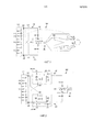
Фиг. 1 - общий вид присоединенного к пациенту медицинского устройства согласно аспектам настоящего раскрытия.FIG. 1 is a perspective view of a patient-attached medical device according to aspects of the present disclosure.
Фиг. 2 - подробный вид одного из вариантов осуществления присоединенного к пациенту медицинского устройства по фиг. 1.FIG. 2 is a detailed view of one embodiment of the patient-attached medical device of FIG. one.
Фиг. 3 - подробный вид еще одного варианта осуществления присоединенного к пациенту медицинского устройства по фиг. 1.FIG. 3 is a detailed view of yet another embodiment of a patient-attached medical device of FIG. one.
Фиг. 4 - подробный вид еще одного другого варианта осуществления присоединенного к пациенту медицинского устройства по фиг. 1.FIG. 4 is a detailed view of yet another embodiment of a patient-attached medical device of FIG. one.
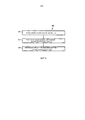
Фиг. 5 иллюстрирует способ ограничения тока утечки согласно аспектам настоящего раскрытия.FIG. 5 illustrates a method for limiting leakage current in accordance with aspects of the present disclosure.
ОПИСАНИЕ ПРЕДПОЧТИТЕЛЬНЫХ ВАРИАНТОВ ВОПЛОЩЕНИЯDESCRIPTION OF PREFERRED EMBODIMENTS
Со ссылкой на фиг. 1 приведено концептуальное представление присоединенного к пациенту медицинского устройства 100 согласно аспектам настоящего раскрытия. Присоединенное к пациенту медицинское устройство 100 применяется соответствующим образом для контроля и/или обеспечения функций поддержки жизнеобеспечения. Кроме того, присоединенное к пациенту медицинское устройство 100 является соответственно мобильным, носимым на человеке-пациенте. В некоторых вариантах осуществления, предполагается, что присоединенное к пациенту медицинское устройство 100 является одним из монитора пациента, электростимулятором сердца, и тому подобным.With reference to FIG. 1 is a conceptual view of a patient-attached
Присоединенное к пациенту медицинское устройство 100 включает в себя электронные компоненты 102, присоединенные к пациенту 104 через одно или более соединений 106 пациента. Предполагается, что соединения 106 пациента присоединяются к пациенту 104 через один или более датчиков и/или электродов 108. В некоторых вариантах осуществления, электронные компоненты 102 принимают данные пациента из соединений 106 пациента. Дополнительно или в качестве альтернативы, в некоторых вариантах осуществления, электронные компоненты 102 выдают сигналы на соединения 106 пациента. Например, если пациент 104 страдает от нарушений ритма, сигналы могут выдаваться на одно из соединений 106 пациента для управления связанным электродом из датчиков и/или электродов 108, с тем чтобы давать импульс сердцу пациента и поддерживать надлежащее сердечное сокращение.A patient-attached
Батарейный отсек 110 присоединенного к пациенту медицинского устройства 100 принимает одну или более аккумуляторных батарей 112 и выдает питание с аккумуляторных батарей 112 на электронные компоненты 102 присоединенного к пациенту медицинского устройства 100. Соответственно, батарейный отсек 110 включает в себя одну или более клемм 114 присоединения аккумуляторных батарей, которые сопрягаются с клеммами аккумуляторных батарей 112 и соединяют аккумуляторные батареи 112 последовательно. В некоторых вариантах осуществления, когда аккумуляторные батареи 112 вставляются в батарейный отсек 110, клеммы 114 присоединения аккумуляторных батарей недоступны снаружи. То есть никто не может осуществить доступ к клеммам 114 присоединения аккумуляторных батарей у аккумуляторных батарей 112 извне батарейного отсека 110. Несмотря на то что это типично достигается физической конструкцией батарейного отсека 110, механический и/или электромеханический подходы к достижению этого также предполагаются.The
Расположенное между электронными компонентами 102 и батарейным отсеком 110 присоединенное к пациенту медицинское устройство 100 включает в себя первый набор 116 из одного или более переключающих устройств 118 и второй набор 120 из одного или более переключающих устройств 122. Каждое из переключающих устройств 118, 122 включает в себя один или более электронных переключателей, таких как полевые транзисторы (FET), триоды для переменного тока (симисторы, TRIAC), реле и тому подобное. Кроме того, типично, переключающие устройства 118 первого набора 116 соединены последовательно, и/или переключающие устройства 122 второго набора 120 соединены последовательно.Between the
Первый набор 116 и второй набор 120 соединены проводами, таким образом, исключается случайное протекание тока от любой из клемм 114 присоединения аккумуляторных батарей на пациента 104 независимо от порядка установки аккумуляторных батарей 112 и/или полярности (правильной или неправильной) аккумуляторных батарей 112. Первый набор 116 избирательно присоединяет, непосредственно или опосредованно, первый выход 124 питания батарейного отсека 110 к первому входу 126 питания электронных компонентов 102, а второй набор 120 избирательно присоединяет, непосредственно или опосредованно, второй выход 128 питания батарейного отсека 110 к второму входу 130 питания электронных компонентов 102. Под «опосредованно» подразумевается, что дополнительные электронные компоненты, такие как резисторы, размещены между одними из переключающих устройств 118, 122 и одним или более из входов 126, 130 питания, выходов 124, 128 питания и другими из переключающих устройств 118, 122. Типично, первый выход 124 питания и первый вход 126 питания являются положительными, а второй выход 128 питания и второй вход 130 питания являются отрицательными. Однако в некоторых вариантах осуществления полярность аккумуляторных батарей 112 может быть изменена на прямо противоположную, в силу чего первый выход 124 питания и первый вход 126 питания могут быть отрицательными, а второй выход 128 питания и второй вход 130 питания могут быть положительными.The
Первый набор 116 и второй набор 120 управляются электронным образом противоположной полярностью полного входного напряжения, так что наборы 116, 120 не соединяют свои соответственные входы питания со своими соответственными выходами питания до тех пор, пока не установлены все аккумуляторные батареи 112. То есть первый набор 116 электронным образом управляется первой полярностью полного входного напряжения, а второй набор 120 электронным образом управляется второй полярностью, противоположной первой полярности, полного входного напряжения. Полное входное напряжение является напряжением, выводимым батарейным отсеком 110 (то есть напряжением, на первом выходе 124 питания и втором выходе 128 питания), когда полностью заполнен всеми аккумуляторными батареями. В некоторых вариантах осуществления, это управление реализуется посредством управления первым набором 116 по второму выходу 128 питания батарейного отсека 110 и вторым набором 120 по первому выходу 124 питания батарейного отсека 110, как проиллюстрировано.The
Без переключающих устройств 118, 122 и при условии, что меньше чем все аккумуляторные батареи 112 установлены в батарейный отсек 110, пациент 104 может соприкасаться с одной из клемм 114 присоединения аккумуляторных батарей, и ток утечки может происходить в результате. Например, если третья батарея 132 из аккумуляторных батарей 112 не установлена, ток может течь из других 134 аккумуляторных батарей 112 к пациенту через первую цепь 136 и одно из соединений 106 пациента. Предполагается, что первая цепь 136 может возникать в результате непосредственного контакта пациента 104 с одной 138 из клемм 114 присоединения аккумуляторных батарей третьей одной 132 из аккумуляторных батарей 112, или опосредованно, например, ухаживающего, одновременно касающегося одной 138 из клемм 114 присоединения аккумуляторных батарей и пациента 104.Without switching
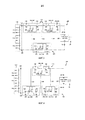
Со ссылкой на фиг. 2 приведен подробный вариант осуществления присоединенного к пациенту медицинского устройства 100 согласно аспектам настоящего раскрытия. Первый набор 116 включает в себя первое переключающее устройство 140, а второй набор 120 включает в себя второе переключающее устройство 142. Первое переключающее устройство 140 включает в себя два FET 144 с каналом p-типа, соединенных встречно-последовательно, и резистор 146, а второе переключающее устройство 142 включает в себя два FET 148 с каналом n-типа, соединенных встречно-последовательно, и резистор 150. FET 144, 148 соединены встречно-последовательно для предохранения тока от протекания в обоих направлениях через переключающие устройства 140, 142, так как каждый из FET 144, 148 включает в себя диод 152 подложки, который предоставляет току возможность протекать в одном направлении через FET независимо от того, закрыт он или открыт. Резисторы 146, 150 применяются вместе с диодами 152 подложки для электрического смещения FET 144, 148.With reference to FIG. 2 is a detailed embodiment of a patient-attached
Сигнал 154 управления из второго выхода 128 питания батарейного отсека 110 электронным образом управляет FET 144 с каналом p-типа, а сигнал 156 управления из первого выхода 128 питания батарейного отсека 110 электронным образом управляет FET 148 с каналом n-типа. Другими словами, сигналы 154, 156 управления для переключающих устройств 140, 142 перекрестно присоединены к противоположным полярностям полного входного напряжения. Ток может течь, если только полное входное напряжение, когда все аккумуляторные батареи 112 установлены в батарейный отсек 110, находится выше напряжения включения перехода затвор-исток FET 144, 148. Перекрестное соединение сигналов 154, 156 управления FET 144, 148 изолирует сигналы 154, 156 управления, так чтобы не могло быть полной цепи через пациента 104 и обратно в аккумуляторные батареи 102.The control signal 154 from the
Одна из проблем у применения FET, как показано на фиг. 2, состоит в том, что есть непреднамеренные обратные цепи. Например, если бы третья батарея 132 из аккумуляторных батарей 112 не была установлена и пациент был должен касаться одной 138 из клемм 114 присоединения аккумуляторных батарей, ток мог бы течь с первого входа 126 питания через один 158 из диодов 152 подложки и резистор 146 первого переключающего устройства 140 на второй выход 128 питания. Соответственно, этот вариант осуществления главным образом используется с механической блокировкой или конструкцией для загораживания доступа к клеммам 114 присоединения аккумуляторных батарей или в устройствах, которые не приспособлены под сердечную функцию (CF). Решение описано в дальнейшем на фиг. 3 и 4. Потенциально возможная непреднамеренная обратная цепь является результатом диодов 152 подложки, в силу чего должно быть принято во внимание, что она не обязательно применима к другим электронным переключателям.One of the problems with applying FET, as shown in FIG. 2, is that there are unintended reverse circuits. For example, if a
Несмотря на то что переключающие устройства 140, 142, раскрытые в связи с фиг. 2, выполнены под FET, должно быть принято во внимание, что другие электронные переключатели, такие как реле и симисторы, могут применяться вместо FET. Кроме того, должно быть принято во внимание, что, когда применяются другие электронные устройства, схемы, воплощающие переключающие устройства 140, 142, будут отличаться от тех, что проиллюстрированы. Например, нет обязательного однозначного соответствия между другими электронными переключателями и FET 144, 148. Каждое из переключающих устройств 140, 142 имеет множество FET, так как диоды 152 подложки предоставляют току возможность течь в одном направлении. Другие электронные переключатели, такие как реле, могут не страдать от такого ограничения, в силу чего потребовался бы всего лишь одиночный электронный переключатель.Although the switching devices 140, 142 disclosed in connection with FIG. 2 are made under FET, it should be taken into account that other electronic switches, such as relays and triacs, can be used instead of FET. In addition, it should be appreciated that when other electronic devices are used, circuits embodying switching devices 140, 142 will be different from those illustrated. For example, there is no mandatory one-to-one correspondence between other electronic switches and
Со ссылкой на фиг. 3 приведен еще один подробный вариант осуществления присоединенного к пациенту медицинского устройства 100 согласно аспектам настоящего раскрытия. Первый набор 116 включает в себя первое переключающее устройство 160 последовательно со вторым переключающим устройством 162, а второй набор 120 включает в себя третье переключающее устройство 164. Первое переключающее устройство 160 и второе переключающее устройство 162 каждое включает в себя два FET 166 с каналом p-типа, соединенных встречно-последовательно, резистор 168 и необязательный конденсатор 170. Кроме того, третье переключающее устройство 164 включает в себя два FET 172 с каналом n-типа, соединенных встречно-последовательно, резистор 174 и необязательный конденсатор 176. FET 166, 172 соединены встречно-последовательно для исключения протекания тока в обоих направлениях через переключающие устройства 160, 162, 164, так как каждый из FET 166, 172 включает в себя диод 178 подложки, который предоставляет току возможность протекать в одном направлении через FET независимо от того, закрыт он или открыт. Резисторы 168, 174 применяются вместе с диодами 178 подложки для электрического смещения FET 166, 172. Конденсаторы 170, 176 по выбору включены в состав для стабилизации переключающего режима.With reference to FIG. 3 is yet another detailed embodiment of a patient-attached
Сигнал 180 управления из второго выхода 128 питания батарейного отсека 110 электронным образом управляет FET 166 с каналом р-типа первого переключающего устройства 160 и второго переключающего устройства 162, а сигнал 182 управления с выхода или входа (в зависимости от протекания тока) первого переключающего устройства 160 электронным образом управляет FET 164 с каналом n-типа третьего переключающего устройства 164 или второго переключающего устройства 162. Кроме того, сигнал 184 управления с выхода или входа (в зависимости от протекания тока) третьего переключающего устройства 164 электронным образом управляет FET 166 с каналом р-типа второго переключающего устройства 162 или второго входа питания 130. Другими словами, первый набор 116 электронным образом управляется противоположной полярностью полного входного напряжения, как второй набор 120. Ток может течь, если только полное входное напряжение, когда все аккумуляторные батареи 112 установлены в батарейный отсек 110, находится выше напряжения включения перехода затвор-исток FET 166, 172.The control signal 180 from the
Как отмечено выше, вариант осуществления по фиг. 2 страдает от непреднамеренных обратных цепей при применении FET вследствие диодов 152 подложки. Настоящий вариант осуществления предотвращает эти непреднамеренные обратные цепи, применяя дополнительное переключающее устройство. Например, если бы третья батарея 132 из аккумуляторных батарей 112 не была установлена и пациент был должен касаться клеммы 138 из клемм 114 присоединения аккумуляторных батарей, ток не мог бы течь с первого входа 126 питания через один 186 из диодов 178 подложки и резистор 168 второго переключающего устройства 162 на второй выход 128 питания вследствие третьего переключающего устройства 164.As noted above, the embodiment of FIG. 2 suffers from unintended reverse circuits when applying FET due to
Несмотря на то что переключающие устройства 160, 162, 164, раскрытые в связи с фиг. 3, выполнены под FET, должно быть принято во внимание, что другие электронные переключатели, такие как реле и симисторы, могут применяться вместо FET. Кроме того, должно быть принято во внимание, что, когда применяются другие электронные устройства, схемы, воплощающие переключающие устройства 160, 162, 164, будут отличаться от тех, что проиллюстрированы. Например, нет обязательного однозначного соответствия между другими электронными переключателями и FET 166, 172. Каждое из переключающих устройств 160, 162, 164 требовало множества FET, так как диоды 178 подложки предоставляют току возможность течь в одном направлении. Другие электронные ключи, такие как реле, могут не страдать от такой проблемы, в силу чего потребовался бы всего лишь одиночный электронный переключатель.Although the switching devices 160, 162, 164 disclosed in connection with FIG. 3 are made under FET, it should be taken into account that other electronic switches, such as relays and triacs, can be used instead of FET. In addition, it should be appreciated that when other electronic devices are used, circuits embodying switching devices 160, 162, 164 will be different from those illustrated. For example, there is no mandatory one-to-one correspondence between other electronic switches and
Со ссылкой на фиг. 4 приведен еще один другой подробный вариант осуществления присоединенного к пациенту медицинского устройства 100 согласно аспектам настоящего раскрытия. Первый набор 116 включает в себя первое переключающее устройство 188, а второй набор 120 включает в себя второе переключающее устройство 190 последовательно с третьим переключающим устройством 192. Первое переключающее устройство 188 включает в себя два FET 194 с каналом р-типа, соединенных встречно-последовательно, резистор 196 и необязательный конденсатор 198. Кроме того, второе переключающее устройство 190 и третье переключающее устройство 192 каждое включает в себя два FET 200 с каналом n-типа, соединенных встречно-последовательно, резистор 202 и необязательный конденсатор 204.With reference to FIG. 4 is yet another detailed embodiment of a patient-attached
FET 194, 200 соединены встречно-последовательно для предохранения тока от протекания в обоих направлениях через переключающие устройства 188, 190, 192, так как каждый из FET 194, 200 включает в себя диод 206 подложки, который предоставляет току возможность протекать в одном направлении через FET независимо от того, закрыт он или открыт. Резисторы 196, 202 применяются вместе с диодами 206 подложки для электрического смещения FET 194, 200. Конденсаторы 198, 204 по выбору включены в состав для стабилизации режима переключения.
Сигнал 208 управления с выхода или входа (в зависимости от протекания тока) второго переключающего устройства 190 электронным образом управляет FET 194 с каналом р-типа первого переключающего устройства 188. Кроме того, сигнал 210 управления с первого выхода 124 питания батарейного отсека 110 электронным образом управляет FET 200 с каналом n-типа второго переключающего устройства 190, а сигнал 212 управления с выхода или входа (в зависимости от протекания тока) первого переключающего устройства 188 электронным образом управляет FET 200 с каналом n-типа третьего переключающего устройства 192 и второго переключающего устройства 190. Другими словами, первый набор 116 электронным образом управляется противоположной полярностью полного входного напряжения, как второй набор 120, т.е. первое переключающее устройство 188 управляется третьим переключающим устройством 192. Ток может течь, если только полное входное напряжение, когда все аккумуляторные батареи 112 установлены в батарейный отсек 110, находится выше напряжения включения перехода затвор-исток FET 194, 200.The control signal 208 from the output or input (depending on the flow of current) of the second switching device 190 electronically controls the
Как отмечено выше, вариант осуществления по фиг. 2 страдает от непреднамеренных обратных цепей при применении FET вследствие диодов 152 подложки. Настоящий вариант осуществления предотвращает эти непреднамеренные обратные цепи, применяя дополнительное переключающее устройство. Например, если бы третья одна 132 из аккумуляторных батарей 112 не была установлена и пациент был должен касаться одной 138 из клемм 114 присоединения аккумуляторных батарей, ток не мог бы течь с первого входа 126 питания через один 214 из диодов 206 подложки третьего переключающего устройства 192 на первый выход 124 питания и/или второй выход 128 питания, вследствие первого переключающего устройства 188 и/или второго переключающего устройства 190.As noted above, the embodiment of FIG. 2 suffers from unintended reverse circuits when applying FET due to
Несмотря на то что переключающие устройства 188, 190, 192, раскрытые в связи с фиг. 4, выполнены как FET, должно быть принято во внимание, что другие электронные переключатели, такие как реле и симисторы, могут применяться вместо FET. Кроме того, должно быть принято во внимание, что, когда применяются другие электронные устройства, схемы, воплощающие переключающие устройства 188, 190, 192, будут отличаться от тех, что проиллюстрированы. Например, нет обязательного однозначного соответствия между другими электронными переключателями и FET 194, 200. Каждое из переключающих устройств 188, 190, 192 требовало множества FET, так как диоды 206 подложки предоставляют току возможность течь в одном направлении. Другие электронные ключи, такие как реле, могут не страдать от такой проблемы, в силу чего потребовался бы всего лишь одиночный электронный переключатель.Although the switching devices 188, 190, 192 disclosed in connection with FIG. 4 are designed as FETs, it should be appreciated that other electronic switches, such as relays and triacs, can be used instead of FETs. In addition, it should be appreciated that when other electronic devices are used, circuits embodying switching devices 188, 190, 192 will be different from those illustrated. For example, there is no mandatory one-to-one correspondence between the other electronic switches and the
Со ссылкой на фиг. 5 проиллюстрирован способ 500 электрического ограничения тока утечки в присоединенном к пациенту медицинском устройстве 100. Аккумуляторная батарея 112 вставляется 502 в батарейный отсек 110 из условия, чтобы аккумуляторная батарея 112 была электрически присоединена к выходу 124, 128 питания и одной или более клемм 114 присоединения аккумуляторных батарей батарейного отсека 110. Выход 124, 128 питания является одним из первого выхода 124 питания и второго выхода 128 питания. Одновременно с или после вставки 502, одна из клемм 114 присоединения аккумуляторных батарей соединяется 504 с пациентом 104, где электрическое соединение является независимым от соединений 106 пациента. Например, медсестра прикасается к клемме присоединения аккумуляторной батареи и пациенту 104 во время замены аккумуляторных батарей 114. В качестве еще одного примера, пациент 104 случайно прикасается к клемме присоединения аккумуляторных батарей. После этого электрический ток между выходом 124, 128 питания и соответствующим входом 126, 130 питания блокируется 506 до тех пор, пока входное напряжение не является полным входным напряжением. Типично, первый набор 116 и/или второй набор 120 содействуют блокированию электрического тока посредством замыкания связанных переключающих устройств, только когда полное входное напряжение является полным входным напряжением. Кроме того, полное входное напряжение является напряжением, выводимым батарейным отсеком 110, полностью загруженным аккумуляторными батареями.With reference to FIG. 5, a
Изобретение было описано со ссылкой на предпочтительные варианты осуществления. Модификации и изменения могут приходить на ум по прочтении и осмыслении предшествующего подробного описания. Предполагается, что изобретение будет построено в качестве включающего в себя все такие модификации и изменения, насколько они подпадают под объем прилагаемой формулы изобретения или ее эквивалентов.The invention has been described with reference to preferred embodiments. Modifications and changes may come to mind after reading and comprehending the previous detailed description. It is intended that the invention be constructed as including all such modifications and changes as they fall within the scope of the appended claims or their equivalents.
Claims (30)
Applications Claiming Priority (3)
| Application Number | Priority Date | Filing Date | Title |
|---|---|---|---|
| US201161442312P | 2011-02-14 | 2011-02-14 | |
| US61/442,312 | 2011-02-14 | ||
| PCT/IB2012/050546 WO2012110913A2 (en) | 2011-02-14 | 2012-02-07 | Electrical means to limit leakage current in battery operated patient-connected medical devices |
Publications (2)
| Publication Number | Publication Date |
|---|---|
| RU2013141917A RU2013141917A (en) | 2015-03-27 |
| RU2607922C2 true RU2607922C2 (en) | 2017-01-11 |
Family
ID=45774279
Family Applications (1)
| Application Number | Title | Priority Date | Filing Date |
|---|---|---|---|
| RU2013141917A RU2607922C2 (en) | 2011-02-14 | 2012-02-07 | Electric device for leakage current limitation in medical devices, connected to patient, operating from accumulator batteries |
Country Status (7)
| Country | Link |
|---|---|
| US (1) | US10116133B2 (en) |
| EP (1) | EP2675352A2 (en) |
| JP (1) | JP6154328B2 (en) |
| CN (1) | CN103370003B (en) |
| BR (1) | BR112013020360A2 (en) |
| RU (1) | RU2607922C2 (en) |
| WO (1) | WO2012110913A2 (en) |
Families Citing this family (2)
| Publication number | Priority date | Publication date | Assignee | Title |
|---|---|---|---|---|
| US9300129B2 (en) | 2013-03-12 | 2016-03-29 | Ascensia Diabetes Care Holding Ag | Reverse battery protection for battery-powered devices |
| WO2022007490A1 (en) * | 2020-07-06 | 2022-01-13 | 上海鑫律通生命科技有限公司 | System for treating arrhythmias using pulsed electric field ablation technology |
Citations (8)
| Publication number | Priority date | Publication date | Assignee | Title |
|---|---|---|---|---|
| US4423456A (en) * | 1981-11-13 | 1983-12-27 | Medtronic, Inc. | Battery reversal protection |
| JPH02281553A (en) * | 1989-04-21 | 1990-11-19 | Matsushita Electric Ind Co Ltd | Battery holder unit |
| JPH04284349A (en) * | 1991-03-14 | 1992-10-08 | Tokyo Electric Co Ltd | Electric appliance |
| JPH05192300A (en) * | 1992-01-22 | 1993-08-03 | Terumo Corp | Portable type medical treating device |
| JPH1097876A (en) * | 1996-09-24 | 1998-04-14 | Matsushita Electric Works Ltd | Charging apparatus |
| JP2000323108A (en) * | 1999-05-06 | 2000-11-24 | Seiko Instruments Inc | Battery pack |
| US20030174449A1 (en) * | 2002-03-15 | 2003-09-18 | Makita Corporation | Power tools |
| RU2221304C2 (en) * | 1999-01-25 | 2004-01-10 | Шеирчун ЛАМ | Switch |
Family Cites Families (12)
| Publication number | Priority date | Publication date | Assignee | Title |
|---|---|---|---|---|
| US4578628A (en) | 1985-01-04 | 1986-03-25 | Motorola Inc. | Portable battery powered electrical apparatus with improved battery pack protected against inadvertent short circuit of the battery terminals |
| JPH0524315A (en) * | 1991-07-23 | 1993-02-02 | Canon Inc | Backup power supply of recording apparatus |
| US5287013A (en) | 1992-02-03 | 1994-02-15 | Motorola, Inc. | Battery compartment safety interlock |
| JP3735871B2 (en) * | 1994-03-02 | 2006-01-18 | ソニー株式会社 | Battery device |
| AU2002221109A1 (en) * | 2000-12-14 | 2002-06-24 | Art Haven 9 Co., Ltd. | Body impedance measuring instrument |
| US7364457B2 (en) * | 2003-12-02 | 2008-04-29 | Larry Mehki | Battery hookup assembly |
| JP4235540B2 (en) | 2003-12-03 | 2009-03-11 | キヤノン株式会社 | Battery housing device |
| JP2009501995A (en) * | 2005-07-21 | 2009-01-22 | コーニンクレッカ フィリップス エレクトロニクス エヌ ヴィ | Software controlled mechanical lock for portable electronic devices |
| JP4942602B2 (en) * | 2007-09-26 | 2012-05-30 | 三洋電機株式会社 | Power supply for vehicle |
| JP5386075B2 (en) * | 2007-09-28 | 2014-01-15 | 株式会社日立製作所 | Multi-series battery control system |
| CN201238141Y (en) * | 2008-07-25 | 2009-05-13 | 冠捷投资有限公司 | Drain current protection device |
| DE202008017194U1 (en) | 2008-12-31 | 2009-07-23 | Telefonaktiebolaget Lm Ericsson (Publ) | Overvoltage / reverse voltage protection circuit |
-
2012
- 2012-02-07 BR BR112013020360A patent/BR112013020360A2/en not_active Application Discontinuation
- 2012-02-07 RU RU2013141917A patent/RU2607922C2/en active
- 2012-02-07 EP EP12706689.2A patent/EP2675352A2/en not_active Ceased
- 2012-02-07 US US13/984,857 patent/US10116133B2/en active Active
- 2012-02-07 CN CN201280008826.1A patent/CN103370003B/en active Active
- 2012-02-07 WO PCT/IB2012/050546 patent/WO2012110913A2/en active Application Filing
- 2012-02-07 JP JP2013553054A patent/JP6154328B2/en active Active
Patent Citations (8)
| Publication number | Priority date | Publication date | Assignee | Title |
|---|---|---|---|---|
| US4423456A (en) * | 1981-11-13 | 1983-12-27 | Medtronic, Inc. | Battery reversal protection |
| JPH02281553A (en) * | 1989-04-21 | 1990-11-19 | Matsushita Electric Ind Co Ltd | Battery holder unit |
| JPH04284349A (en) * | 1991-03-14 | 1992-10-08 | Tokyo Electric Co Ltd | Electric appliance |
| JPH05192300A (en) * | 1992-01-22 | 1993-08-03 | Terumo Corp | Portable type medical treating device |
| JPH1097876A (en) * | 1996-09-24 | 1998-04-14 | Matsushita Electric Works Ltd | Charging apparatus |
| RU2221304C2 (en) * | 1999-01-25 | 2004-01-10 | Шеирчун ЛАМ | Switch |
| JP2000323108A (en) * | 1999-05-06 | 2000-11-24 | Seiko Instruments Inc | Battery pack |
| US20030174449A1 (en) * | 2002-03-15 | 2003-09-18 | Makita Corporation | Power tools |
Also Published As
| Publication number | Publication date |
|---|---|
| CN103370003A (en) | 2013-10-23 |
| EP2675352A2 (en) | 2013-12-25 |
| WO2012110913A2 (en) | 2012-08-23 |
| RU2013141917A (en) | 2015-03-27 |
| CN103370003B (en) | 2016-04-27 |
| BR112013020360A2 (en) | 2017-11-14 |
| JP6154328B2 (en) | 2017-06-28 |
| US20130313917A1 (en) | 2013-11-28 |
| JP2014508586A (en) | 2014-04-10 |
| WO2012110913A3 (en) | 2013-05-10 |
| US10116133B2 (en) | 2018-10-30 |
Similar Documents
| Publication | Publication Date | Title |
|---|---|---|
| TWI501382B (en) | Serial connection/parallel connection switching type cell voltage balance circuit having switches consisted of mosfet, and driving circuit thereof | |
| WO2003096508A9 (en) | Power supply unit | |
| US20150231398A1 (en) | Rechargeable-Battery Implantable Medical Device Having a Primary Battery Active During a Rechargeable-Battery Undervoltage Condition | |
| KR20130053386A (en) | Control circuitry and method for controlling a bi-directional switch system, a bi-directional switch, a switching matrix and a medical stimulator | |
| CN104364993B (en) | Wireless parasite power supplier and employ its electronic equipment | |
| RU2607922C2 (en) | Electric device for leakage current limitation in medical devices, connected to patient, operating from accumulator batteries | |
| RU2555116C2 (en) | Device with internal energy transfer | |
| CN105743476A (en) | Turn-on and turn-off circuit | |
| JP2014104248A (en) | Semiconductor circuit, and living tissue stimulation device provided with semiconductor circuit | |
| CN106253888B (en) | Bidirectional MOSFET switch and multiplexer | |
| CN110268498A (en) | Switchgear | |
| Cha et al. | A single-input dual-output 13.56 MHz CMOS AC–DC converter with comparator-driven rectifiers for implantable devices | |
| JP2012533330A5 (en) | ||
| CN102572041A (en) | Mobile phone with semiconductor laser physiotherapy function | |
| CN110007221A (en) | It is combined switching circuit and its fault detection method | |
| TW201244322A (en) | Charge-discharge control circuit and battery device | |
| CN103841711B (en) | A kind of LED emergence lighting lamp and drive circuit thereof | |
| CN102823135B (en) | For the commutation circuit of switching electric potential | |
| CN204391888U (en) | With the power supply of handoff functionality | |
| CN104160622A (en) | High voltage current switch circuit | |
| JP2014508586A5 (en) | ||
| CN117439236B (en) | Isolation circuit and method of charging contact of beauty instrument and beauty instrument | |
| CN212435611U (en) | Dental chair motor control circuit and dental chair | |
| CN219760704U (en) | Intelligent AC/DC dual-power automatic switching device and kitchen and toilet equipment | |
| CN217159672U (en) | Time delay circuit |