RU2607724C2 - Wave multiplexer and method and program of faulty section identification - Google Patents
Wave multiplexer and method and program of faulty section identification Download PDFInfo
- Publication number
- RU2607724C2 RU2607724C2 RU2015106912A RU2015106912A RU2607724C2 RU 2607724 C2 RU2607724 C2 RU 2607724C2 RU 2015106912 A RU2015106912 A RU 2015106912A RU 2015106912 A RU2015106912 A RU 2015106912A RU 2607724 C2 RU2607724 C2 RU 2607724C2
- Authority
- RU
- Russia
- Prior art keywords
- optical
- transponders
- optical signal
- local
- fiber optic
- Prior art date
Links
Images


Classifications
-
- H—ELECTRICITY
- H04—ELECTRIC COMMUNICATION TECHNIQUE
- H04J—MULTIPLEX COMMUNICATION
- H04J14/00—Optical multiplex systems
- H04J14/02—Wavelength-division multiplex systems
- H04J14/0201—Add-and-drop multiplexing
- H04J14/0202—Arrangements therefor
- H04J14/021—Reconfigurable arrangements, e.g. reconfigurable optical add/drop multiplexers [ROADM] or tunable optical add/drop multiplexers [TOADM]
- H04J14/0212—Reconfigurable arrangements, e.g. reconfigurable optical add/drop multiplexers [ROADM] or tunable optical add/drop multiplexers [TOADM] using optical switches or wavelength selective switches [WSS]
-
- H—ELECTRICITY
- H04—ELECTRIC COMMUNICATION TECHNIQUE
- H04Q—SELECTING
- H04Q11/00—Selecting arrangements for multiplex systems
- H04Q11/0001—Selecting arrangements for multiplex systems using optical switching
- H04Q11/0005—Switch and router aspects
-
- H—ELECTRICITY
- H04—ELECTRIC COMMUNICATION TECHNIQUE
- H04B—TRANSMISSION
- H04B10/00—Transmission systems employing electromagnetic waves other than radio-waves, e.g. infrared, visible or ultraviolet light, or employing corpuscular radiation, e.g. quantum communication
- H04B10/07—Arrangements for monitoring or testing transmission systems; Arrangements for fault measurement of transmission systems
- H04B10/075—Arrangements for monitoring or testing transmission systems; Arrangements for fault measurement of transmission systems using an in-service signal
- H04B10/079—Arrangements for monitoring or testing transmission systems; Arrangements for fault measurement of transmission systems using an in-service signal using measurements of the data signal
- H04B10/0797—Monitoring line amplifier or line repeater equipment
-
- H—ELECTRICITY
- H04—ELECTRIC COMMUNICATION TECHNIQUE
- H04B—TRANSMISSION
- H04B10/00—Transmission systems employing electromagnetic waves other than radio-waves, e.g. infrared, visible or ultraviolet light, or employing corpuscular radiation, e.g. quantum communication
- H04B10/07—Arrangements for monitoring or testing transmission systems; Arrangements for fault measurement of transmission systems
- H04B10/075—Arrangements for monitoring or testing transmission systems; Arrangements for fault measurement of transmission systems using an in-service signal
- H04B10/079—Arrangements for monitoring or testing transmission systems; Arrangements for fault measurement of transmission systems using an in-service signal using measurements of the data signal
- H04B10/0799—Monitoring line transmitter or line receiver equipment
-
- H—ELECTRICITY
- H04—ELECTRIC COMMUNICATION TECHNIQUE
- H04B—TRANSMISSION
- H04B10/00—Transmission systems employing electromagnetic waves other than radio-waves, e.g. infrared, visible or ultraviolet light, or employing corpuscular radiation, e.g. quantum communication
- H04B10/25—Arrangements specific to fibre transmission
-
- H—ELECTRICITY
- H04—ELECTRIC COMMUNICATION TECHNIQUE
- H04J—MULTIPLEX COMMUNICATION
- H04J14/00—Optical multiplex systems
-
- H—ELECTRICITY
- H04—ELECTRIC COMMUNICATION TECHNIQUE
- H04J—MULTIPLEX COMMUNICATION
- H04J14/00—Optical multiplex systems
- H04J14/02—Wavelength-division multiplex systems
-
- H—ELECTRICITY
- H04—ELECTRIC COMMUNICATION TECHNIQUE
- H04J—MULTIPLEX COMMUNICATION
- H04J14/00—Optical multiplex systems
- H04J14/02—Wavelength-division multiplex systems
- H04J14/0201—Add-and-drop multiplexing
- H04J14/0202—Arrangements therefor
- H04J14/0204—Broadcast and select arrangements, e.g. with an optical splitter at the input before adding or dropping
-
- H—ELECTRICITY
- H04—ELECTRIC COMMUNICATION TECHNIQUE
- H04J—MULTIPLEX COMMUNICATION
- H04J14/00—Optical multiplex systems
- H04J14/02—Wavelength-division multiplex systems
- H04J14/0201—Add-and-drop multiplexing
- H04J14/0202—Arrangements therefor
- H04J14/0205—Select and combine arrangements, e.g. with an optical combiner at the output after adding or dropping
-
- H—ELECTRICITY
- H04—ELECTRIC COMMUNICATION TECHNIQUE
- H04J—MULTIPLEX COMMUNICATION
- H04J14/00—Optical multiplex systems
- H04J14/02—Wavelength-division multiplex systems
- H04J14/0201—Add-and-drop multiplexing
- H04J14/0215—Architecture aspects
- H04J14/0217—Multi-degree architectures, e.g. having a connection degree greater than two
-
- H—ELECTRICITY
- H04—ELECTRIC COMMUNICATION TECHNIQUE
- H04Q—SELECTING
- H04Q11/00—Selecting arrangements for multiplex systems
- H04Q11/0001—Selecting arrangements for multiplex systems using optical switching
- H04Q11/0003—Details
-
- H—ELECTRICITY
- H04—ELECTRIC COMMUNICATION TECHNIQUE
- H04Q—SELECTING
- H04Q3/00—Selecting arrangements
- H04Q3/42—Circuit arrangements for indirect selecting controlled by common circuits, e.g. register controller, marker
- H04Q3/52—Circuit arrangements for indirect selecting controlled by common circuits, e.g. register controller, marker using static devices in switching stages, e.g. electronic switching arrangements
-
- H—ELECTRICITY
- H04—ELECTRIC COMMUNICATION TECHNIQUE
- H04Q—SELECTING
- H04Q11/00—Selecting arrangements for multiplex systems
- H04Q11/0001—Selecting arrangements for multiplex systems using optical switching
- H04Q11/0005—Switch and router aspects
- H04Q2011/0007—Construction
- H04Q2011/0015—Construction using splitting combining
-
- H—ELECTRICITY
- H04—ELECTRIC COMMUNICATION TECHNIQUE
- H04Q—SELECTING
- H04Q11/00—Selecting arrangements for multiplex systems
- H04Q11/0001—Selecting arrangements for multiplex systems using optical switching
- H04Q11/0005—Switch and router aspects
- H04Q2011/0007—Construction
- H04Q2011/0016—Construction using wavelength multiplexing or demultiplexing
-
- H—ELECTRICITY
- H04—ELECTRIC COMMUNICATION TECHNIQUE
- H04Q—SELECTING
- H04Q2213/00—Indexing scheme relating to selecting arrangements in general and for multiplex systems
- H04Q2213/1301—Optical transmission, optical switches
-
- H—ELECTRICITY
- H04—ELECTRIC COMMUNICATION TECHNIQUE
- H04Q—SELECTING
- H04Q2213/00—Indexing scheme relating to selecting arrangements in general and for multiplex systems
- H04Q2213/13295—Wavelength multiplexing, WDM
-
- H—ELECTRICITY
- H04—ELECTRIC COMMUNICATION TECHNIQUE
- H04Q—SELECTING
- H04Q2213/00—Indexing scheme relating to selecting arrangements in general and for multiplex systems
- H04Q2213/13367—Hierarchical multiplexing, add-drop multiplexing
Abstract
Description
[ОБЛАСТЬ ТЕХНИКИ, К КОТОРОЙ ОТНОСИТСЯ ИЗОБРЕТЕНИЕ][FIELD OF THE INVENTION]
Настоящее изобретение относится к волновому мультиплексору и к способу и программе для идентификации неисправного участка и, в частности, относится к волновому мультиплексору и подобному устройству, которые могут эффективно идентифицировать неисправный участок.The present invention relates to a wave multiplexer and to a method and program for identifying a faulty section and, in particular, relates to a wave multiplexer and similar device that can efficiently identify a faulty section.
[УРОВЕНЬ ТЕХНИКИ][BACKGROUND OF THE INVENTION]
Фотонные сети являются сетями, которые зависят исключительно от оптических методов (без преобразования оптического сигнала в электрический сигнал) реализации таких сетевых функций, как передача, мультиплексирование, демультиплексирование, переключение и управление каналами. Еще до возникновения фотонных сетей оптические волокна применялись в качестве каналов передачи и оптические усилители применялись для усиления сигнала, но переключение каналов было осуществимо только электрическими методами. В частности, оптический сигнал приходилось преобразовывать в электрический сигнал. Таким образом, пропускная способность в сети ограничена производительностью переключающего устройства.Photonic networks are networks that depend solely on optical methods (without converting the optical signal into an electrical signal) implementing such network functions as transmission, multiplexing, demultiplexing, switching and channel control. Even before the advent of photon networks, optical fibers were used as transmission channels and optical amplifiers were used to amplify the signal, but channel switching was possible only by electrical methods. In particular, the optical signal had to be converted into an electrical signal. Thus, network bandwidth is limited by the performance of the switching device.
Переключение электрических цепей требует очень большого расхода энергии в устройстве, которое все более увеличивается с повышением скорости передачи данных и увеличением числа систем каналов передачи, которые могут быть задействованы. Для удовлетворения потребности в осуществлении как высокоскоростной связи, так и низкого роста расхода энергии по времени, в настоящее время интенсивно исследовались и разрабатывались методы оптического переключения, осуществляющие переключение посредством непосредственного использования оптического сигнала, без потребности в преобразовании в электрический сигнал.Switching electrical circuits requires a very large energy consumption in the device, which is increasingly increasing with increasing data transfer speed and increasing the number of transmission channel systems that can be involved. To satisfy the need for both high-speed communication and low growth in energy consumption over time, optical switching methods that switch using direct use of an optical signal without the need for conversion into an electrical signal have been intensively studied and developed.
Фиг. 4 представляет схему конфигурации волнового мультиплексора 900 (бесцветный/всенаправленный/бесконфликтный перестраиваемый оптический мультиплексор ввода/вывода (CDC ROADM)) в соответствии с известным методом оптического переключения. Волновой мультиплексор 900 подсоединен к WDM-маршрутам (маршрутам с мультиплексированием с разделением по длинам волн) 901, 902 и 903 в качестве множества систем волоконно-оптических линий связи и вводит и выводит оптический сигнал в и из каждый(ого) WDM-маршрут(а).FIG. 4 is a configuration diagram of a wavelength multiplexer 900 (colorless / omnidirectional / conflict-free tunable optical input / output multiplexer (CDC ROADM)) in accordance with a known optical switching method. The
Каждый WDM-маршрут вводит и выводит оптический сигнал в и из транспондеры(ов) 921, 922 и 923 посредством модуля 910 разветвления и выбора. Транспондеры 921, 922 и 923 преобразуют электрический или оптический сигнал, передаваемый от каждого клиента в оптический или электрический сигнал. Каналы между модулем 910 разветвления и выбора и каждым из транспондеров 921, 922 и 923 называются клиентским каналом.Each WDM route inputs and outputs an optical signal to and from transponder (s) 921, 922, and 923 via a branch and
На фиг. 4 показаны три системы WDM-маршрутов 901, 902 и 903 и три системы транспондеров 921, 922 и 923 вследствие ограничения размером листа. К реальному мультиплексору 900 могут быть подсоединены большие числа WDM-маршрутов и транспондеров. Кроме того, число систем не обязательно должно одинаковым между WDM-маршрутами и транспондерами.In FIG. 4 shows three
Модуль 910 разветвления и выбора включает в себя: оптические ответвители 911, соответствующие оптическим сигналам, передаваемым и принимаемым по WDM-маршрутам; и оптические переключатели 912, соответствующие оптическим сигналам, передаваемым и принимаемым транспондерами. Каждый оптический сигнал, принятый из WDM-маршрута 901, разветвляется разветвителем 901a, и каждый оптический сигнал, полученный мультиплексированием в мультиплексоре 901b, вводится в WDM-маршрут 901. Аналогичные разветвители 902a и 903a и мультиплексоры 902b и 903b, соответственно, соединены с другими WDM-маршрутами 902 и 903.The branching and
Выходные оптические сигналы из разветвителя 901a WDM-маршрута 901 вводятся в оптический ответвитель 911a, мультиплексор 902b WDM-маршрута 902 и мультиплексор 903b WDM-маршрута 903. Аналогично, выходные оптические сигналы из разветвителя 902a WDM-маршрута 902 вводятся в оптический ответвитель 911b, мультиплексор 901b WDM-маршрута 901 и мультиплексор 903b WDM-маршрута 903. Выходные оптические сигналы из разветвителя 903a WDM-маршрута 903 вводятся в оптический ответвитель 911c, мультиплексор 901b WDM-маршрута 901 и мультиплексор 902b WDM-маршрута 902.The output optical signals from the splitter 901a of the
Мультиплексор 901b WDM-маршрута 901 мультиплексирует выходные сигналы из оптического ответвителя 911d, разветвителя 902a WDM-маршрута 902 и разветвителя 903a WDM-маршрута 903 и выводит результирующий сигнал в WDM-маршрут 901. Аналогично, мультиплексор 902b WDM-маршрута 902 мультиплексирует выходные сигналы из оптического ответвителя 911e, разветвителя 901a WDM-маршрута 901 и разветвителя 903a WDM-маршрута 903 и выводит результирующий сигнал в WDM-маршрут 902. Мультиплексор 903b WDM-маршрута 903 мультиплексирует выходные сигналы из оптического ответвителя 911f, разветвителя 901a WDM-маршрута 901 и разветвителя 902a WDM-маршрута 902 и выводит результирующий сигнал в WDM-маршрут 903.A multiplexer 901b of the
Оптические переключатели 912a - 912c выбирают, каждый, один из выходных оптических сигналов из мультиплексоров 901b - 903b WDM-маршрутов 901 – 903 и вводят выбранный сигнал в транспондеры 921 - 923. Оптические переключатели 912d - 912f выбирают, каждый, один из разветвителей 901a - 903a WDM-маршрутов 901 – 903 и выводят выходной оптический сигнал из транспондеров 921 - 923 в выбранный пункт назначения.The optical switches 912a through 912c select each one of the output optical signals from the multiplexers 901b through 903b of the
Когда выходной оптический сигнал из разветвителя 901a WDM-маршрута 901 должен приниматься транспондером 921, оптический переключатель 912a может выбирать оптический сигнал, передаваемый из оптического ответвителя 911a, так что будет установлен канал вывода. Когда оптический сигнал должен передаваться в мультиплексор 901b WDM-маршрута 901 транспондером 921, оптический переключатель 912d может выбирать оптический ответвитель 911d в качестве пункта назначения выходного оптического сигнала, так что будет установлен канал ввода.When the output optical signal from the splitter 901a of the
Авторы настоящего изобретения уже выпустили приведенный волновой мультиплексор 900 на рынок в 2011 г. (NPL (непатентная публикация) 2) в качестве устройства, поддерживающего 100 Гбит/с Ethernet (зарегистрированный товарный знак), и в настоящее время осуществляется техническая разработка устройства для получения более высокой скорости и большей пропускной способности.The inventors of the present invention already launched the 900 wave multiplexer on the market in 2011 (NPL (Non-Patent Publication) 2) as a device supporting 100 Gb / s Ethernet (registered trademark), and the device is currently undergoing technical development to obtain more high speed and greater bandwidth.
Технические публикации, имеющие отношение к устройству, включают в себя: PTL (патентная техническая публикация) 1, описывающая систему оптического узла, которая может обеспечить расширение функциональных возможностей и поиск неисправностей в сети при невысоких затратах путем использования n×n оптических переключателей; NPL 1, представляющая последние тенденции в вышеописанной фотонной сети; и NPL 2, описывающая волновой мультиплексор, поддерживающий 100 Гбит/с Ethernet, который уже выпущен на рынок авторами настоящего изобретения, как изложено выше.Technical publications related to the device include: PTL (Patent Technical Publication) 1, which describes an optical node system that can provide enhanced functionality and network troubleshooting at low cost by using n × n optical switches; NPL 1, representing the latest trends in the above photonic network; and NPL 2, which describes a wave multiplexer supporting 100 Gb / s Ethernet, which has already been put on the market by the authors of the present invention, as described above.
[СПИСОК БИБЛИОГРАФИЧЕСКИХ ССЫЛОК][LIST OF BIBLIOGRAPHIC REFERENCES]
[ПАТЕНТНАЯ ПУБЛИКАЦИЯ][PATENT PUBLICATION]
PTL 1: Опубликованная японская патентная заявка № 2001-268011PTL 1: Published Japanese Patent Application No. 2001-268011
[НЕПАТЕНТНЫЕ ПУБЛИКАЦИИ][NON-PATENT PUBLICATIONS]
NPL 1: Kenichi Kitayama, «Technical trend of Photonic Network», September 9, 2011, [найдено 9 июля, 2012 г.], SCAT LINE Vol. 87, Photonic Internet Forum, (Support Center for Advanced Telecommunications Technology Research Foundation), Internet-сайт <URL:http://www.scat.or.jp/scatline/scatline87/pdf/scat87_report01.pdf>NPL 1: Kenichi Kitayama, “Technical trend of Photonic Network”, September 9, 2011, [found July 9, 2012], SCAT LINE Vol. 87, Photonic Internet Forum, (Support Center for Advanced Telecommunications Technology Research Foundation), Internet site <URL: http: //www.scat.or.jp/scatline/scatline87/pdf/scat87_report01.pdf>
NPL 2: «NEC Launches Network Failure Resistant, Non-Blocking Optical Cross-Connect Transmission Apparatus for 100 Gbit/s Transmission (Press Release)», June 9, 2011, [найдено 9 июля, 2012], NEC Corporation, Internet-сайт <URL:http://www.nec.co.jp/press/ja/1106/0802.html>NPL 2: “NEC Launches Network Failure Resistant, Non-Blocking Optical Cross-Connect Transmission Apparatus for 100 Gbit / s Transmission (Press Release)”, June 9, 2011, [found July 9, 2012], NEC Corporation, Internet site <URL: http: //www.nec.co.jp/press/ja/1106/0802.html>
[СУЩНОСТЬ ИЗОБРЕТЕНИЯ][SUMMARY OF THE INVENTION]
[ТЕХНИЧЕСКАЯ ЗАДАЧА][TECHNICAL PROBLEM]
К сожалению, волновой мультиплексор 900 требует утомительной работы, предусматривающей значительное время и много труда, когда какая-либо из систем передачи отказывает. В частности, оптический кабель требуется подсоединять/отсоединять, и систему передачи требуется переключать вручную, чтобы идентифицировать, возникла ли неисправность на участке до или после модуля 910 разветвления и выбора.Unfortunately, the
Метод, раскрытый в PTL 1, предназначен для поддержки связи при возникновении неисправности посредством обхода неисправности и не предназначен для идентификации неисправного участка. Ни NPL 1, ни NPL 2 не раскрывают метода, который может решить вышеописанную проблему.The method disclosed in PTL 1 is intended to support communication in the event of a malfunction by bypassing the malfunction and is not intended to identify a malfunctioning area. Neither NPL 1 nor NPL 2 discloses a method that can solve the above problem.
Целью настоящего изобретения является создание волнового мультиплексора и способа и программы для идентификации неисправного участка, которые могут эффективно идентифицировать, находится ли неисправный участок до или после модуля разветвления и выбора.The aim of the present invention is to provide a wave multiplexer and method and program for identifying a faulty section, which can effectively identify whether the faulty section is before or after the branching and selection module.
[РЕШЕНИЕ ЗАДАЧИ][THE SOLUTION OF THE PROBLEM]
Для достижения этой цели, волновой мультиплексор в соответствии с настоящим изобретением является волновым мультиплексором, который соединен с и обеспечен между множеством систем или одной системой волоконно-оптических линий связи и множеством систем или одной системой оптических транспондеров и вводит и выводит оптический сигнал в и из волоконно-оптические(х) линии(й) связи и оптические(х) транспондеры(ров). Волновой мультиплексор содержит: первые оптические переключатели, которые выводят входной оптический сигнал из волоконно-оптических линий связи в оптические транспондеры; вторые оптические переключатели, которые выводят входной оптический сигнал из оптических транспондеров в волоконно-оптические линии связи; и локальную оптическую схему кольцевой проверки, которая закольцовывает и выводит входной оптический сигнал из любого из оптических транспондеров в сторону этого оптического транспондера.To achieve this, the wave multiplexer in accordance with the present invention is a wave multiplexer that is connected to and provided between a plurality of systems or one system of optical fiber communication lines and a plurality of systems or one system of optical transponders and inputs and outputs an optical signal to and from a fiber -optical (x) communication lines (y) and optical (x) transponders (ditch). The wave multiplexer comprises: first optical switches that output an input optical signal from fiber-optic communication lines to optical transponders; second optical switches that output the input optical signal from the optical transponders to fiber optic communication lines; and a local optical loopback circuit, which loops and outputs the input optical signal from any of the optical transponders towards this optical transponder.
Для достижения цели, способ идентификации неисправного участка в соответствии настоящим изобретением является способом идентификации неисправного участка, выполняемым блоком модульной проверки, включенным в модуль разветвления и выбора, включенный в волновой мультиплексор. Модуль разветвления и выбора соединен с множеством систем волоконно-оптических линий связи и оптическими транспондерами и вводит и выводит оптический сигнал в и из волоконно-оптические(х) линии(й) связи и оптические(х) транспондеры(ров). Модуль разветвления и выбора включает в себя: локальную оптическую схему кольцевой проверки, которая закольцовывает и выводит входной оптический сигнал из любого из оптических транспондеров в сторону этого оптического транспондера; первые оптические переключатели, которые выборочно выводят оптический сигнал, принимаемый из волоконно-оптических линий связи, или оптический сигнал, закольцованный локальной оптической схемой кольцевой проверки, в оптические транспондеры посредством внешней переключающей операции; вторые оптические переключатели, которые выборочно выводят оптический сигнал, принимаемый из оптических транспондеров, в одну систему волоконно-оптических линий связи или локальную оптическую схему кольцевой проверки посредством внешней переключающей операции; и блок модульной проверки, который работает согласно внешней операционной команде. Способ включает в себя: этап управления переключением первых оптических переключателей для того, чтобы выводить оптический сигнал, закольцованный локальной оптической схемой кольцевой проверки, в оптические транспондеры; одновременно, этап управления переключением вторых оптических переключателей для того, чтобы выводить оптический сигнал, принимаемый из оптических транспондеров, в локальную оптическую схему кольцевой проверки; и затем этап назначения оптическим транспондерам задания срабатывать и испускать оптический сигнал и этап определения, приняли ли оптические транспондеры оптический сигнал, закольцованный локальной оптической схемой кольцевой проверки.To achieve the goal, a method for identifying a faulty section in accordance with the present invention is a method for identifying a faulty section performed by a unit checking unit included in a branching and selection module included in a wave multiplexer. The branching and selection module is connected to a plurality of systems of fiber-optic communication lines and optical transponders and inputs and outputs an optical signal to and from fiber-optic (x) communication lines (s) and optical (x) transponders (ditches). The branching and selection module includes: a local optical loopback circuit, which loops and outputs the input optical signal from any of the optical transponders toward this optical transponder; first optical switches that selectively output an optical signal received from fiber-optic communication lines or an optical signal looped back by a local optical loopback circuit to optical transponders by an external switching operation; second optical switches that selectively output the optical signal received from the optical transponders into a single fiber optic communication system or a local optical loopback circuit by an external switching operation; and a unit test unit that operates according to an external operating command. The method includes: the step of controlling the switching of the first optical switches in order to output the optical signal looped by the local optical loopback circuit to the optical transponders; at the same time, the step of controlling the switching of the second optical switches in order to output the optical signal received from the optical transponders to the local optical loopback circuit; and then the step of assigning the optical transponders the task to trigger and emit the optical signal and the step of determining whether the optical transponders received the optical signal looped back by the local optical loopback circuit.
Для достижения цели, программа для идентификации неисправного участка в соответствии настоящим изобретением является программой для идентификации неисправного участка, содержащей процессы, выполняемые процессором, включенным в блок модульной проверки, включенный в модуль разветвления и выбора, включенный в волновой мультиплексор. Модуль разветвления и выбора соединен с множеством систем волоконно-оптических линий связи и оптическими транспондерами и вводит и выводит оптический сигнал в и из волоконно-оптические(х) линии(й) связи и оптические(х) транспондеры(ров). Модуль разветвления и выбора включает в себя: локальную оптическую схему кольцевой проверки, которая закольцовывает и выводит входной оптический сигнал из любого из оптических транспондеров в сторону этого оптического транспондера; первые оптические переключатели, которые выборочно выводят оптический сигнал, принимаемый из волоконно-оптических линий связи, или оптический сигнал, закольцованный локальной оптической схемой кольцевой проверки, в оптические транспондеры посредством внешней переключающей операции; вторые оптические переключатели, которые выборочно выводят оптический сигнал, принимаемый из оптических транспондеров в одну систему волоконно-оптических линий связи или локальную оптическую схему кольцевой проверки посредством внешней переключающей операции; и блок модульной проверки, который работает согласно внешней операционной команде. Процессы включают в себя: переключение первых оптических переключателей для того, чтобы выводить оптический сигнал, закольцованный локальной оптической схемой кольцевой проверки, в оптические транспондеры; одновременно, переключение вторых оптических переключателей для того, чтобы выводить оптический сигнал, принимаемый из оптических транспондеров, в локальную оптическую схему кольцевой проверки; и затем предписание оптическим транспондерам срабатывать и испускать оптический сигнал и определение, приняли ли оптические транспондеры оптический сигнал, закольцованный локальной оптической схемой кольцевой проверки.To achieve the goal, a program for identifying a faulty region in accordance with the present invention is a program for identifying a faulty region comprising processes performed by a processor included in a unit test unit included in a branching and selection module included in a wave multiplexer. The branching and selection module is connected to a plurality of systems of fiber-optic communication lines and optical transponders and inputs and outputs an optical signal to and from fiber-optic (x) communication lines (s) and optical (x) transponders (ditches). The branching and selection module includes: a local optical loopback circuit, which loops and outputs the input optical signal from any of the optical transponders toward this optical transponder; first optical switches that selectively output an optical signal received from fiber-optic communication lines or an optical signal looped back by a local optical loopback circuit to optical transponders by an external switching operation; second optical switches that selectively output an optical signal received from the optical transponders into a single fiber optic communication system or a local optical loopback circuit through an external switching operation; and a unit test unit that operates according to an external operating command. The processes include: switching the first optical switches in order to output the optical signal looped back by the local optical loopback circuit into optical transponders; at the same time, switching the second optical switches in order to output the optical signal received from the optical transponders into the local optical loopback circuit; and then, instructing the optical transponders to operate and emit an optical signal, and determining whether the optical transponders received the optical signal looped back by the local optical loopback circuit.
[ПОЛОЖИТЕЛЬНЫЙ РЕЗУЛЬТАТ ИЗОБРЕТЕНИЯ][POSITIVE RESULT OF THE INVENTION]
Настоящее изобретение может обеспечить волновой мультиплексор и способ и программу для идентификации неисправного участка, которые имеют уникальную функцию, которая дает возможность эффективно идентифицировать, находится ли неисправный участок до или после модуля разветвления и выбора, с конфигурацией, включающей в себя локальную оптическую схему кольцевой проверки, которая закольцовывает и выводит входной оптический сигнал из любого из оптических транспондеров в сторону этого оптического транспондера, как изложено выше.The present invention can provide a wave multiplexer and method and program for identifying a faulty section, which have a unique function that makes it possible to efficiently identify whether the faulty section is before or after the branching and selection module, with a configuration including a local optical loopback circuit, which loops and outputs the input optical signal from any of the optical transponders towards this optical transponder, as described above.
[КРАТКОЕ ОПИСАНИЕ ЧЕРТЕЖЕЙ][BRIEF DESCRIPTION OF THE DRAWINGS]
Фиг. 1 – схема, поясняющая конфигурацию волнового мультиплексора в соответствии с первым примерным вариантом осуществления настоящего изобретения.FIG. 1 is a diagram for explaining a configuration of a wave multiplexer according to a first exemplary embodiment of the present invention.
Фиг. 2 – блок-схема последовательности операций, поясняющая обработку данных для идентификации, находится ли неисправный участок до или после модуля разветвления и выбора в волновом мультиплексоре, показанном на фиг. 1.FIG. 2 is a flowchart for explaining data processing for identifying whether a faulty section is located before or after the branching and selection module in the wave multiplexer shown in FIG. one.
Фиг. 3 – схема, поясняющая конфигурацию волнового мультиплексора в соответствии со вторым примерным вариантом осуществления настоящего изобретения.FIG. 3 is a diagram for explaining a configuration of a wave multiplexer according to a second exemplary embodiment of the present invention.
Фиг. 4 – схема, поясняющая конфигурацию волнового мультиплексора в соответствии с известным методом оптического переключения.FIG. 4 is a diagram explaining a configuration of a wave multiplexer in accordance with a known optical switching method.
[ОПИСАНИЕ ВАРИАНТОВ ОСУЩЕСТВЛЕНИЯ][DESCRIPTION OF EMBODIMENTS]
(ПЕРВЫЙ ПРИМЕРНЫЙ ВАРИАНТ ОСУЩЕСТВЛЕНИЯ)(FIRST EXAMPLE EMBODIMENT)
Первый примерный вариант осуществления настоящего изобретения описан ниже со ссылкой на фиг. 1.A first exemplary embodiment of the present invention is described below with reference to FIG. one.
Сначала описана базовая конфигурация настоящего примерного варианта осуществления, и затем будет описана подробная конфигурация.First, a basic configuration of the present exemplary embodiment is described, and then a detailed configuration will be described.
Волновой мультиплексор 100 в соответствии с настоящим примерным вариантом осуществления является волновым мультиплексором, который соединен с множеством систем волоконно-оптических линий связи (WDM-маршрутов 101-103) и оптическими транспондерами (транспондерами 21-23) и вводит и выводит оптический сигнал в и из волоконно-оптические(х) линии(й) связи и оптические(х) транспондеры(ров). Волновой мультиплексор 100 включает в себя: первые оптические переключатели 12a - 12c, которые выводят входной оптический сигнал из волоконно-оптических линий связи в оптические транспондеры; вторые оптические переключатели 12d - 12f, которые выводят входной оптический сигнал из оптических транспондеров в волоконно-оптические линии связи; и локальную оптическую схему 13 кольцевой проверки, которая закольцовывает и выводит входной оптический сигнал из любого из оптических транспондеров в сторону этого оптического транспондера.The
Первые оптические переключатели 12a - 12c выборочно выводят оптический сигнал, принимаемый из волоконно-оптических линий связи, или оптический сигнал, закольцованный локальной оптической схемой кольцевой проверки, в оптические транспондеры посредством внешней переключающей операции. Вторые оптические переключатели 12d - 12f выборочно выводят оптический сигнал, принимаемый из оптических транспондеров в одну систему волоконно-оптических линий связи или локальную оптическую схему кольцевой проверки посредством внешней переключающей операции.The first
Волновой мультиплексор 100 дополнительно включает в себя: оптические ответвители 11a - 11c, которые, каждый, ответвляют оптический сигнал, принимаемый из соответствующей одной из волоконно-оптических линий связи, и выводят результирующий сигнал в каждый оптический транспондер, и вторые оптические ответвители 11d – 11f, которые, каждый, мультиплексируют оптический сигнал, принимаемый из соответствующего одного из оптических транспондеров и выводят результирующий сигнал в каждую волоконно-оптическую линию связи.The
Волновой мультиплексор 100 включает в себя блок 40 модульной проверки, который, согласно внешней операционной команде, переключает первые оптические переключатели для того, чтобы выводить оптический сигнал, закольцованный локальной оптической схемой кольцевой проверки, в оптические транспондеры; одновременно, переключает вторые оптические переключатели для того, чтобы выводить оптический сигнал, принимаемый из оптических транспондеров, в локальную оптическую схему кольцевой проверки; и затем назначает оптическим транспондерам задание испускать оптический сигнал и определяет, приняли ли оптические транспондеры оптический сигнал, закольцованный локальной оптической схемой кольцевой проверки.The
В данной конфигурации, волновой мультиплексор 100 может эффективно идентифицировать, находится ли неисправный участок до или после модуля 10 разветвления и выбора.In this configuration, the
Ниже приведено более подробное описание конфигурации.The following is a more detailed description of the configuration.
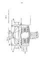
Фиг. 1 является схемой, поясняющей конфигурацию волнового мультиплексора 100 (бесцветного/всенаправленного/бесконфликтного перестраиваемого оптический мультиплексор ввода/вывода (CDC ROADM)) в соответствии с первым примерным вариантом осуществления настоящего изобретения. Волновой мультиплексор 100 подсоединен к WDM-маршрутам 101, 102 и 103 в качестве множества систем волоконно-оптических линий связи и вводит и выводит оптический сигнал в и из каждый(ого) WDM-маршрут(а).FIG. 1 is a diagram explaining a configuration of a wave multiplexer 100 (colorless / omnidirectional / conflict-free tunable optical input / output multiplexer (CDC ROADM)) in accordance with a first exemplary embodiment of the present invention. The
Каждый WDM-маршрут вводит и выводит сигнал в и из транспондеры(ов) 21, 22 и 23 при посредстве модуля 10 разветвления и выбора. Транспондеры 21, 22 и 23 преобразуют электрический или оптический сигнал, передаваемый от каждого клиента в оптический или электрический сигнал. Каналы между модулем 10 разветвления и выбора и каждым из транспондеров 21, 22 и 23 называются клиентским каналом.Each WDM route inputs and outputs a signal to and from transponder (s) 21, 22, and 23 through the branching and
На фиг. 1 показаны три системы WDM-маршрутов 101, 102 и 103 и три системы транспондеров 21, 22 и 23 вследствие ограничения размером листа. К реальному волновому мультиплексору 100 могут быть подсоединены большие числа WDM-маршрутов и транспондеров. Кроме того, число систем не обязательно должно одинаковым между WDM-маршрутами и транспондерами.In FIG. 1 shows three
Модуль 10 разветвления и выбора включает в себя: оптические ответвители 11, которые работают с оптическими сигналами, передаваемыми и принимаемыми по WDM-маршрутам; и оптические переключатели 12, которые работают с оптическими сигналами, передаваемыми и принимаемыми транспондерами. Каждый оптический сигнал, принятый из WDM-маршрута 101, разветвляется разветвителем 101a, и каждый оптический сигнал, полученный мультиплексированием в мультиплексоре 101b, вводится в WDM-маршрут 101. Аналогичные разветвители 102a и 103a и мультиплексоры 102b и 103b, соответственно, соединены с другими WDM-маршрутами 102 и 903.The branching and
Выходные оптические сигналы из разветвителя 101a WDM-маршрута 101 вводятся в оптический ответвитель 11a, мультиплексор 102b WDM-маршрута 102 и мультиплексор 103b WDM-маршрута 103. Аналогично, выходные оптические сигналы из разветвителя 102a WDM-маршрута 102 вводятся в оптический ответвитель 11b, мультиплексор 101b WDM-маршрута 101 и мультиплексор 103b WDM-маршрута 103. Выходные оптические сигналы из разветвителя 103a WDM-маршрута 103 вводятся в оптический ответвитель 11c, мультиплексор 101b WDM-маршрута 101 и мультиплексор 102b WDM-маршрута 102.The output optical signals from the
Мультиплексор 101b WDM-маршрута 101 мультиплексирует выходные сигналы из оптического ответвителя 11d, разветвителя 102a WDM-маршрута 102 и разветвителя 103a WDM-маршрута 103 и выводит результирующий сигнал в WDM-маршрут 101. Аналогично, мультиплексор 102b WDM-маршрута 102 мультиплексирует выходные сигналы из оптического ответвителя 11e, разветвителя 101a WDM-маршрута 101 и разветвителя 103a WDM-маршрута 103 и выводит результирующий сигнал в WDM-маршрут 102. Мультиплексор 103b WDM-маршрута 103 мультиплексирует выходные сигналы из оптического ответвителя 11f, разветвителя 101a WDM-маршрута 101 и разветвителя 102a WDM-маршрута 102 и выводит результирующий сигнал в WDM-маршрут 103.The
Вышеописанная конфигурация является такой же, как для волнового мультиплексора 900 в соответствии с вышеописанным известным методом. Модуль 10 разветвления и выбора, содержащийся в волновом мультиплексоре 100 в соответствии с настоящим примерным вариантом осуществления, дополнительно содержит два оптических ответвителя 11g и 11h. Выходные оптические сигналы из оптического ответвителя 11h непосредственно вводятся в оптический ответвитель 11g. Таким образом, оптические ответвители 11g и 11h также совместно называются локальной оптической схемой 13 кольцевой проверки.The above configuration is the same as for the
Оптические переключатели 12a - 12c выбирают, каждый, один из выходных оптических сигналов из разветвителей 101b - 103b WDM-маршрутов 101-103 и оптического ответвителя 11g и вводят выбранный сигнал в транспондеры 21-23. Оптические переключатели 12d - 12f выбирают, каждый, один из мультиплексоров 101a - 103a WDM-маршрутов 101-103 и оптического ответвителя 11h и выводят выходной оптический сигнал из транспондеров 21 - 23 в выбранный пункт назначения.The
Блок 40 модульной проверки является микрокомпьютером или автономным компьютерным устройством, которое включает в себя процессор 41, который, в основном, выполняет компьютерную программу и соединен с модулем 10 разветвления и выбора. Когда пользователь дает посредством средства 42 ввода и вывода команду блоку 40 модульной проверки выполнять проверку, процессор 41 запускает функционирование программы проверки в качестве средства 43 проверки. Блок 40 модульной проверки дополнительно включает в себя средство накопления, средство связи и т.п., которые не требуются конкретно для описания настоящего изобретения и, следовательно, не будут подробно описаны.
Средство 43 проверки испускает управляющий сигнал для назначения оптическим переключателям 12a - 12f команды переключать оптические сигналы. Средство 43 проверки испускает также управляющий сигнал для назначения транспондерам 21-23 команды выводить свет, чтобы принимать информацию, указывающую мощность, длину волны и т.п. входного оптического сигнала из транспондеров 21-23.The verification means 43 emits a control signal for instructing the
Фиг. 2 является блок-схемой последовательности операций, поясняющей обработку данных для идентификации того, находится ли неисправный участок до или после модуля 10 разветвления и выбора в волновом мультиплексоре 100, показанном на фиг. 1. Средство 43 проверки, которое запустило обработку данных, сначала переключает между оптическими переключателями 12d - 12f, чтобы переключатель, соответствующий одному из транспондеров 21-23 в качестве целевого объекта проверки, выводил выходные оптические сигналы из целевого транспондера в оптический ответвитель 11h (локальную оптическую схему 13 кольцевой проверки) (этап S201).FIG. 2 is a flowchart for explaining data processing for identifying whether a faulty section is located before or after the branching and
В ответ на приведенную процедуру средство 43 проверки переключает между оптическими переключателями 12a - 12c, чтобы выходные оптические сигналы из оптического ответвителя 11g (локальной оптической схемы 13 кольцевой проверки) возвращались на входную сторону целевого объекта проверки в транспондерах 21-23 в качестве целевого объекта проверки (этап S202). При выполнении данных процедур, устанавливается локальное боковое закольцовывание для транспондера в качестве целевого объекта проверки.In response to the above procedure, the verification means 43 switches between the
Затем средство 43 проверки дает целевому объекту проверки в транспондерах 21-23 задание выводить свет (этап S203) и, тем самым, определяет, вводится ли оптический сигнал, возвращенный обратно посредством локальной оптической схемы 13 кольцевой проверки, в целевой объект проверки в транспондерах 21-23 (этап S204).Then, the verification means 43 instructs the verification target in the transponders 21-23 to output light (step S203) and thereby determines whether the optical signal returned back by the local
Когда оптический сигнал ошибочно не вводится, клиентский канал до модуля 10 разветвления и выбора можно определить как содержащий дефект (этап S205). Когда оптический сигнал успешно вводится, WDM-маршруты 101-103 после модуля 10 разветвления и выбора можно определить как содержащие дефект (этап S206). Каждый из результатов определения представляется пользователю с помощью средства 42 ввода и вывода (этап S207) и, таким образом, обработка данных, выполняемая средством 43 проверки, заканчивается.When the optical signal is not erroneously inputted, the client channel up to the branching and
Например, соответствующим ли образом соединен клиентский канал между модулем 10 разветвления и выбора и транспондером 21, можно проверить следующим образом. В частности, средство 43 проверки выполняет переключение на этапе S201 таким образом, что оптический переключатель 12d выводит выходной оптический сигнал из транспондера 21 в оптический ответвитель 11h. Упомянутый выходной оптический сигнал возвращается обратно в оптический ответвитель 11g и, таким образом, средство 43 проверки выполняет переключение на этапе S202 таким образом, что оптический переключатель 12a вводит данный выходной оптический сигнал из оптического ответвителя 11g в транспондер 21.For example, whether the client channel is properly connected between the branching and
Таким образом, если клиентский канал между модулем 10 разветвления и выбора и транспондером 21 содержит дефект, то выходной оптический сигнал не возвращается обратно на входную сторону вследствие неполного оптического закольцовывания. Следовательно, очевидно, что клиентский канал содержит дефект. Клиентские каналы между другими транспондерами 22 и 23 и модулем 10 разветвления и выбора можно проверить аналогичным образом, чтобы понять, существует ли в них дефект.Thus, if the client channel between the branching and
(ОБЩАЯ ОБРАБОТКА ДАННЫХ В ПЕРВОМ ПРИМЕРНОМ ВАРИАНТЕ ОСУЩЕСТВЛЕНИЯ)(GENERAL DATA PROCESSING IN THE FIRST EXAMPLE IMPLEMENTATION OPTION)
Ниже приведено описание общей обработки данных в вышеупомянутом примерном варианте осуществления.The following is a description of general data processing in the above exemplary embodiment.
Способ идентификации неисправного участка в соответствии с примерным вариантом осуществления выполняется блоком 40 модульной проверки, включенным в модуль 10 разветвления и выбора, включенный в волновой мультиплексор 100. Модуль 10 разветвления и выбора соединен с множеством систем волоконно-оптических линий связи и оптическими транспондерами и вводит и выводит оптический сигнал в и из волоконно-оптические(х) линии(й) связи и оптические(х) транспондеры(ров). Модуль 10 разветвления и выбора включает в себя: локальную оптическую схему 13 кольцевой проверки, которая закольцовывает и выводит входной оптический сигнал из любого из оптических транспондеров в сторону этого оптического транспондера; первые оптические переключатели 12a - 12c, которые выборочно выводят оптический сигнал, принимаемый из волоконно-оптических линий связи, или оптический сигнал, закольцованный локальной оптической схемой кольцевой проверки, в оптические транспондеры посредством внешней переключающей операции; вторые оптические переключатели 12d - 12f, которые выборочно выводят оптический сигнал, принимаемый из оптических транспондеров в одну систему волоконно-оптических линий связи или локальную оптическую схему кольцевой проверки посредством внешней переключающей операции; и блок 40 модульной проверки, который работает согласно внешней операционной команде. Способ включает в себя: этап управления переключением первых оптических переключателей для того, чтобы выводить оптический сигнал, закольцованный локальной оптической схемой кольцевой проверки, в оптические транспондеры (этап S201 на фиг. 2); одновременно этап управления переключением вторых оптических переключателей для того, чтобы выводить оптический сигнал, принимаемый из оптических транспондеров, в локальную оптическую схему кольцевой проверки (этап S202 на фиг. 2); затем этап назначения оптическим транспондерам задания срабатывать и испускать оптический сигнал (этап S203 на фиг. 2); и этап определения, приняли ли оптические транспондеры оптический сигнал, закольцованный локальной оптической схемой кольцевой проверки (этап S204 на фиг. 2).A method for identifying a faulty section in accordance with an exemplary embodiment is performed by a
Вышеописанные операционные этапы могут быть обеспечены в компьютерно-выполняемой программе таким образом, что программа может выполняться процессором 41 в блоке 40 модульной проверки, который непосредственно выполняет вышеописанные этапы. Программа может быть записана на некратковременном носителе записи, например DVD (универсальном цифровом диске), CD (компакт-диске) и во флэш-памяти. В данном случае программа считывается с носителя записи и выполняется компьютером.The above-described operational steps can be provided in a computer-executable program so that the program can be executed by the
Благодаря приведенной работе настоящий примерный вариант осуществления обеспечивает следующие полезные результаты.Thanks to the above work, the present exemplary embodiment provides the following useful results.
В настоящем примерном варианте осуществления, когда в волновом мультиплексоре возникает неисправность, можно надежно и легко идентифицировать, находится ли неисправный участок до или после модуля разветвления и выбора. Во время процедуры не требуется ни выполнения утомительной работы, например, ручного отсоединения/подсоединения оптического кабеля и переключения системы передачи, ни специального измерительного устройства. Все, что требуется, это выдать простую команду для выполнения проверки в блок 40 модульной проверки, и блок 40 модульной проверки выполнит проверку.In the present exemplary embodiment, when a malfunction occurs in the wave multiplexer, it is possible to reliably and easily identify whether the malfunctioning portion is before or after the branching and selection module. During the procedure, neither tedious work is required, for example, manually disconnecting / connecting an optical cable and switching the transmission system, or a special measuring device. All that is required is to issue a simple command to perform the check to the
Блок 40 модульной проверки может иметь непосредственное соединение с волновым мультиплексором 100 и может удаленно работать с волновым мультиплексором 100 по сети и т.п. Когда техническое обслуживание можно выполнять посредством дистанционного выполнения, можно значительно уменьшить объем работ и стоимость технического обслуживания.The
Локальную оптическую схему кольцевой проверки, возможно, не обязательно обеспечивать для каждой системы транспондеров 21-23. Единственная система локальной оптической схемы кольцевой проверки в волновом мультиплексоре 100, в целом, может быть совместно используемой всеми системами. Приведенная конфигурация может значительно сократить стоимость мультиплексора и способствовать уменьшению размеров и сокращению затрат.It may not be necessary to provide a local loopback optical circuit for each transponder system 21-23. The only local loopback optical circuit system in
(ВТОРОЙ ПРИМЕРНЫЙ ВАРИАНТ ОСУЩЕСТВЛЕНИЯ)(SECOND EXAMPLE EMBODIMENT)
Волновой мультиплексор 300 в соответствии со вторым примерным вариантом осуществления настоящего изобретения включает в себя, в дополнение к конфигурации, описанной в первом примерном варианте осуществления, удаленную оптическую схему 314 кольцевой проверки, которая закольцовывает и выводит входной оптический сигнал из любой из волоконно-оптических линий связи в сторону этой волоконно-оптической линии связи. Кроме того, оптические переключатели 11a - 11c выборочно выводят оптический сигнал, принимаемый из волоконно-оптических линий связи, или оптический сигнал, закольцованный локальной оптической схемой кольцевой проверки, в оптические транспондеры или удаленную оптическую схему кольцевой проверки посредством внешней переключающей операции. Вторые оптические переключатели 11d - 11f выборочно выводят оптический сигнал, принимаемый из оптических транспондеров или удаленной оптической схемы кольцевой проверки, в любую систему из множества систем волоконно-оптических линий связи или локальную оптическую схему кольцевой проверки посредством внешней переключающей операции.The
Кроме обеспечения таких же полезных результатов, как в первом примерном варианте осуществления, приведенная конфигурация может обнаруживать дефект в устройстве на другой стороне, соединенной с волновым мультиплексором 300 по волоконно-оптической линии связи. В данном случае отсутствует потребность изменения конфигурации устройства на другой стороне.In addition to providing the same useful results as in the first exemplary embodiment, the above configuration can detect a defect in the device on the other side connected to the
Ниже приведено более подробное описание данной конфигурации.The following is a more detailed description of this configuration.
Фиг. 3 является схемой, поясняющей конфигурацию волнового мультиплексора 300 в соответствии со вторым примерным вариантом осуществления настоящего изобретения. Поскольку волновой мультиплексор 300, в основном, содержит такую же конфигурацию, как конфигурация волнового мультиплексора 100 в соответствии с вышеописанным первым примерным вариантом осуществления, то одинаковые элементы обозначены одинаковыми названиями и позициями, и их описания в дальнейшем не приводятся.FIG. 3 is a diagram for explaining a configuration of a
Модуль 310 разветвления и выбора, содержащийся в волновом мультиплексоре 300, дополнительно включает в себя, кроме конфигурации, описанной в первом примерном варианте осуществления, два оптических переключателя 312g и 312h. Выходные оптические сигналы из оптических переключателей 312g непосредственно вводятся в оптические переключатели 312h. Таким образом, оптические переключатели 312g и 312h совместно называются также удаленной оптической схемой 314 кольцевой проверки.The branching and
Например, соответствующим ли образом подсоединен WDM-маршрут 101 после модуля 310 разветвления и выбора можно проверить с помощью вышеупомянутого удаленной оптической схемы кольцевой проверки следующим образом. В частности, оптический переключатель 312g выполняет переключение таким образом, что выходной оптический сигнал из оптического ответвителя 11a выводится в оптический переключатель 312h. Тогда оптический переключатель 312h выполняет переключение таким образом, что оптический сигнал выводится в оптический ответвитель 11d.For example, whether the
Таким образом, если WDM-маршрут 101 после модуля 310 разветвления и выбора является неисправным, то дефект можно обнаруживать в устройстве на другой стороне, соединенной с волновым мультиплексором 300 посредством WDM-маршрута 101. Таким образом, очевидно, что WDM-маршрут 101 имеет дефект. Другие WDM-маршруты 102 и 103 можно проверять сходным образом, чтобы выяснить, присутствует ли в них дефект. В данном случае устройство на другой стороне может не иметь конфигурации, аналогичные конфигурации в настоящем варианте осуществления.Thus, if the
Настоящее изобретение описано выше со ссылкой на конкретные примерные варианты осуществления, изображенные на прилагаемых чертежах, но настоящее изобретение не ограничено примерными вариантами осуществления, изображенными на чертежах. Любую известную конфигурацию можно принять при условии, что она обеспечивает полезные результаты настоящего изобретения.The present invention is described above with reference to specific exemplary embodiments shown in the accompanying drawings, but the present invention is not limited to the exemplary embodiments depicted in the drawings. Any known configuration may be accepted provided that it provides useful results of the present invention.
Ниже приведен обзор новых технических признаков вышеописанных примерных вариантов осуществления. Хотя примерные варианты осуществления могут быть частично или полностью суммированы как новый метод, как описано ниже, настоящее изобретение не обязательно ограничено этим.The following is an overview of the new technical features of the above exemplary embodiments. Although exemplary embodiments may be partially or fully summarized as a new method, as described below, the present invention is not necessarily limited thereto.
(Дополнительное замечание 1) Волновой мультиплексор, соединенный с и обеспеченный между множеством систем или одной системой волоконно-оптических линий связи и множеством систем или одной системой оптических транспондеров и вводящий и выводящий оптический сигнал в и из волоконно-оптические(х) линии(й) связи и оптические(х) транспондеры(ров), при этом волновой мультиплексор содержит:(Supplementary Note 1) A wave multiplexer connected to and provided between a plurality of systems or one system of fiber optic communication lines and a plurality of systems or one system of optical transponders and inputting and outputting an optical signal to and from fiber optic (x) line (s) communications and optical (x) transponders (ditch), while the wave multiplexer contains:
первые оптические переключатели, которые выводят входной оптический сигнал из волоконно-оптических линий связи в оптические транспондеры;first optical switches that output an input optical signal from fiber optic communication lines to optical transponders;
вторые оптические переключатели, которые выводят входной оптический сигнал из оптических транспондеров в волоконно-оптические линии связи; иsecond optical switches that output the input optical signal from the optical transponders to fiber optic communication lines; and
локальную оптическую схему кольцевой проверки, которая закольцовывает и выводит входной оптический сигнал из любого из оптических транспондеров в сторону этого оптического транспондера.a local optical loopback circuit, which loops and outputs the input optical signal from any of the optical transponders towards this optical transponder.
(Дополнительное замечание 2) Волновой мультиплексор в соответствии с дополнительным замечанием 1, в котором первые оптические переключатели выполняют функцию выборочного вывода оптического сигнала, принимаемого из волоконно-оптических линий связи, или оптического сигнала, закольцованного локальной оптической схемой кольцевой проверки, в оптические транспондеры посредством внешней переключающей операции, и(Supplementary remark 2) The wave multiplexer according to supplementary remark 1, in which the first optical switches perform the function of selectively outputting an optical signal received from fiber-optic communication lines, or an optical signal looped back by a local optical loopback circuit, to optical transponders by means of an external switching operation, and
вторые оптические переключатели выполняют функцию выборочного вывода оптического сигнала, принимаемого из оптических транспондеров в одну систему волоконно-оптических линий связи или локальную оптическую схему кольцевой проверки посредством внешней переключающей операции.the second optical switches perform the function of selectively outputting the optical signal received from the optical transponders into one system of fiber-optic communication lines or a local optical loopback circuit by means of an external switching operation.
(Дополнительное замечание 3) Волновой мультиплексор в соответствии с дополнительным замечанием 2, дополнительно включающий в себя: первые оптические ответвители, которые, каждый, ответвляют оптический сигнал, принимаемый из соответствующей одной из волоконно-оптических линий связи, и выводят результирующий сигнал в каждый первый оптический переключатель; и(Supplementary Note 3) The wave multiplexer according to Supplementary Note 2, further comprising: first optical couplers, which each branch an optical signal received from a respective one of the optical fiber communication lines, and output the resulting signal to each first optical switch; and
вторые оптические ответвители, которые, каждый, мультиплексируют оптический сигнал, принимаемый из соответствующего одного из вторых оптических переключателей, и выводят результирующий сигнал в каждую волоконно-оптическую линию связи.second optical couplers, each of which multiplex the optical signal received from the corresponding one of the second optical switches, and output the resulting signal to each optical fiber communication line.
(Дополнительное замечание 4) Волновой мультиплексор в соответствии с дополнительным замечанием 2, дополнительно включающий в себя блок модульной проверки, который работает согласно внешней операционной команде, при этом(Supplementary Remark 4) The wave multiplexer in accordance with Supplementary Remark 2, further including a modular verification unit that operates according to an external operating command, wherein
блок модульной проверки имеет функцию управления переключением первых оптических переключателей для того, чтобы выводить оптический сигнал, закольцованный локальной оптической схемой кольцевой проверки, в оптические транспондеры,the unit test unit has the function of controlling the switching of the first optical switches in order to output the optical signal looped by the local optical loopback circuit into the optical transponders,
блок модульной проверки имеет функцию, одновременно, управления переключением вторых оптических переключателей для того, чтобы выводить оптический сигнал, принимаемый из оптических транспондеров, в локальную оптическую схему кольцевой проверки, иthe unit of the check module has the function of simultaneously controlling the switching of the second optical switches in order to output the optical signal received from the optical transponders to the local optical loopback circuit, and
блок модульной проверки имеет функцию, после этого, назначения оптическим транспондерам задания испускать оптический сигнал и определения, приняли ли оптические транспондеры оптический сигнал, закольцованный локальной оптической схемой кольцевой проверки.the unit of the check module has the function, then, assigning the optical transponders of the task to emit an optical signal and determining whether the optical transponders received the optical signal looped back by the local optical loopback circuit.
(Дополнительное замечание 5) Волновой мультиплексор в соответствии с дополнительным замечанием 2, дополнительно включающий в себя удаленную оптическую схему кольцевой проверки, которая закольцовывает и выводит входной оптический сигнал из любой из волоконно-оптических линий связи в сторону этой волоконно-оптической линии связи, при этом(Supplementary Remark 5) The wave multiplexer in accordance with Supplementary Remark 2, further including a remote optical loopback circuit, which loops and outputs an input optical signal from any of the fiber optic communication lines towards this fiber-optic communication line,
первые оптические переключатели выполняют функцию выборочного вывода оптического сигнала, принимаемого из волоконно-оптических линий связи, или оптического сигнала, закольцованного локальной оптической схемой кольцевой проверки, в оптические транспондеры или удаленную оптическую схему кольцевой проверки посредством внешней переключающей операции, иthe first optical switches perform the function of selectively outputting an optical signal received from fiber-optic communication lines or an optical signal looped back by a local optical loopback circuit to optical transponders or a remote optical loopback circuit by an external switching operation, and
вторые оптические переключатели выполняют функцию выборочного вывода оптического сигнала, принимаемого из оптических транспондеров или удаленной оптической схемы кольцевой проверки, в любую систему волоконно-оптических линий связи или локальную оптическую схему кольцевой проверки посредством внешней переключающей операции.the second optical switches perform the function of selectively outputting an optical signal received from optical transponders or a remote optical loopback circuit to any fiber optic communication system or a local optical loopback circuit by means of an external switching operation.
(Дополнительное замечание 6) Способ идентификации неисправного участка, выполняемый блоком модульной проверки, включенным в модуль разветвления и выбора, включенный в волновой мультиплексор, при этом модуль разветвления и выбора соединен с множеством систем волоконно-оптических линий связи и оптическими транспондерами и вводит и выводит оптический сигнал в и из волоконно-оптические(х) линии(й) связи и оптические(х) транспондеры(ров),(Supplementary remark 6) A method for identifying a faulty section, performed by a unit check module included in a branching and selection module, included in a wave multiplexer, wherein the branching and selection module is connected to a plurality of fiber-optic communication line systems and optical transponders and inputs and outputs optical a signal to and from fiber optic (x) communication lines (s) and optical (x) transponders (ditches),
модуль разветвления и выбора включает в себя: локальную оптическую схему кольцевой проверки, которая закольцовывает и выводит входной оптический сигнал из любого из оптических транспондеров в сторону этого оптического транспондера; первые оптические переключатели, которые выборочно выводят оптический сигнал, принимаемый из волоконно-оптических линий связи, или оптический сигнал, закольцованный локальной оптической схемой кольцевой проверки, в оптические транспондеры посредством внешней переключающей операции; вторые оптические переключатели, которые выборочно выводят оптический сигнал, принимаемый из оптических транспондеров, в одну систему волоконно-оптических линий связи или локальную оптическую схему кольцевой проверки посредством внешней переключающей операции; и блок модульной проверки, который работает согласно внешней операционной команде, причем способ содержит следующие этапы:the branching and selection module includes: a local optical loopback circuit, which loops and outputs the input optical signal from any of the optical transponders toward this optical transponder; first optical switches that selectively output an optical signal received from fiber-optic communication lines or an optical signal looped back by a local optical loopback circuit to optical transponders by an external switching operation; second optical switches that selectively output the optical signal received from the optical transponders to a single fiber optic communication system or a local optical loopback circuit by an external switching operation; and a unit check unit that operates according to an external operating command, the method comprising the following steps:
управляют переключением первых оптических переключателей для того, чтобы выводить оптический сигнал, закольцованный локальной оптической схемой кольцевой проверки, в оптические транспондеры;controlling the switching of the first optical switches in order to output the optical signal looped back by the local optical loopback circuit to the optical transponders;
одновременно, управляют переключением вторых оптических переключателей для того, чтобы выводить оптический сигнал, принимаемый из оптических транспондеров, в локальную оптическую схему кольцевой проверки; иat the same time, the switching of the second optical switches is controlled in order to output the optical signal received from the optical transponders into the local optical loopback circuit; and
затем предписывают оптическим транспондерам срабатывать и испускать оптический сигнал и определяют, приняли ли оптические транспондеры оптический сигнал, закольцованный локальной оптической схемой кольцевой проверки.then, the optical transponders are instructed to operate and emit an optical signal, and it is determined whether the optical transponders received the optical signal looped back by the local optical loopback circuit.
(Дополнительное замечание 7) Программа для идентификации неисправного участка, содержащая процессы, выполняемые процессором, включенным в блок модульной проверки, включенный в модуль разветвления и выбора, содержащийся в волновом мультиплексоре, при этом модуль разветвления и выбора соединен с множеством систем волоконно-оптических линий связи и оптическими транспондерами и вводит и выводит оптический сигнал в и из волоконно-оптические(х) линии(й) связи и оптические(х) транспондеры(ров),(Supplementary Note 7) A program for identifying a faulty section, comprising processes performed by a processor included in a unit test module included in a branch and select module contained in a wave multiplexer, wherein the branch and select module is connected to a plurality of fiber optic communication line systems and optical transponders and inputs and outputs an optical signal to and from fiber optic (x) communication line (s) and optical (x) transponders (ditch),
модуль разветвления и выбора включает в себя: локальную оптическую схему кольцевой проверки, которая закольцовывает и выводит входной оптический сигнал из любого из оптических транспондеров в сторону этого оптического транспондера; первые оптические переключатели, которые выборочно выводят оптический сигнал, принимаемый из волоконно-оптических линий связи, или оптический сигнал, закольцованный локальной оптической схемой кольцевой проверки, в оптические транспондеры посредством внешней переключающей операции; вторые оптические переключатели, которые выборочно выводят оптический сигнал, принимаемый из оптических транспондеров, в одну систему волоконно-оптических линий связи или локальную оптическую схему кольцевой проверки посредством внешней переключающей операции; и блок модульной проверки, который работает согласно внешней операционной команде,the branching and selection module includes: a local optical loopback circuit, which loops and outputs the input optical signal from any of the optical transponders toward this optical transponder; first optical switches that selectively output an optical signal received from fiber-optic communication lines or an optical signal looped back by a local optical loopback circuit to optical transponders by an external switching operation; second optical switches that selectively output the optical signal received from the optical transponders into a single fiber optic communication system or a local optical loopback circuit by an external switching operation; and a unit check unit that operates according to an external operating command,
процессы включают в себя:processes include:
переключение первых оптических переключателей для того, чтобы выводить оптический сигнал, закольцованный локальной оптической схемой кольцевой проверки, в оптические транспондеры;switching the first optical switches in order to output the optical signal looped back by the local optical loopback circuit into the optical transponders;
одновременно, переключение вторых оптических переключателей для того, чтобы выводить оптический сигнал, принимаемый из оптических транспондеров, в локальную оптическую схему кольцевой проверки; иat the same time, switching the second optical switches in order to output the optical signal received from the optical transponders into the local optical loopback circuit; and
затем предписание оптическим транспондерам срабатывать и испускать оптический сигнал и определение, приняли ли оптические транспондеры оптический сигнал, закольцованный локальной оптической схемой кольцевой проверки.then, instructing the optical transponders to operate and emit an optical signal, and determining whether the optical transponders received the optical signal looped back by the local optical loopback circuit.
Настоящая заявка испрашивает приоритет по японской патентной заявке № 2012-169440, поданной 31 июля 2012 г., содержание которой полностью включено в настоящую заявку путем отсылки.This application claims priority to Japanese Patent Application No. 2012-169440, filed July 31, 2012, the entire contents of which are hereby incorporated by reference.
[ПРОМЫШЛЕННАЯ ПРИМЕНИМОСТЬ][INDUSTRIAL APPLICABILITY]
Настоящее изобретение пригодно для применения к волновым мультиплексорам и, в частности, перестраиваемому оптическому мультиплексору ввода/вывода (ROADM).The present invention is suitable for application to wave multiplexers and, in particular, a tunable optical input / output multiplexer (ROADM).
[СПИСОК ПОЗИЦИЙ][LIST OF POSITIONS]
10, 310 модуль разветвления и выбора10, 310 branching and selection module
11a - 11h оптический ответвитель11a to 11h optical coupler
12a - 12f, 312g - 312h оптический переключатель12a - 12f, 312g - 312h optical switch
13 локальная оптическая схема кольцевой проверки13 local optical loopback circuit
21, 22, 23 транспондер21, 22, 23 transponder
40 модульный блок проверки40 modular check unit
41 процессор41 cpu
42 средство ввода и вывода42 input and output means
43 средство проверки43 means of verification
100, 300 волновой мультиплексор100, 300 wave multiplexer
101, 102, 103 WDM-маршрут101, 102, 103 WDM route
101a, 102a, 103a разветвитель101a, 102a, 103a splitter
101b, 102b, 103b мультиплексор101b, 102b, 103b multiplexer
314 удаленная оптическая схема кольцевой проверки314 remote optical loopback circuit
Claims (28)
Applications Claiming Priority (3)
| Application Number | Priority Date | Filing Date | Title |
|---|---|---|---|
| JP2012-169440 | 2012-07-31 | ||
| JP2012169440 | 2012-07-31 | ||
| PCT/JP2013/069016 WO2014021075A1 (en) | 2012-07-31 | 2013-07-11 | Wavelength multiplexing device, impairment occurrence location identification method and program |
Publications (2)
| Publication Number | Publication Date |
|---|---|
| RU2015106912A RU2015106912A (en) | 2016-09-20 |
| RU2607724C2 true RU2607724C2 (en) | 2017-01-10 |
Family
ID=50027759
Family Applications (1)
| Application Number | Title | Priority Date | Filing Date |
|---|---|---|---|
| RU2015106912A RU2607724C2 (en) | 2012-07-31 | 2013-07-11 | Wave multiplexer and method and program of faulty section identification |
Country Status (6)
| Country | Link |
|---|---|
| US (1) | US9654850B2 (en) |
| JP (1) | JP5858162B2 (en) |
| CN (1) | CN104521159B (en) |
| IN (1) | IN2014DN11164A (en) |
| RU (1) | RU2607724C2 (en) |
| WO (1) | WO2014021075A1 (en) |
Families Citing this family (4)
| Publication number | Priority date | Publication date | Assignee | Title |
|---|---|---|---|---|
| EP2549773B1 (en) * | 2011-07-21 | 2017-10-25 | Orange | Device and method for combining optical components associated with a wavelength in a combined optical component |
| RU2607724C2 (en) * | 2012-07-31 | 2017-01-10 | Нек Корпорейшн | Wave multiplexer and method and program of faulty section identification |
| EP2991253A1 (en) * | 2014-08-25 | 2016-03-02 | Xieon Networks S.à r.l. | Reconfigurable add/drop multiplexing in optical networks |
| CN111211833B (en) * | 2020-01-15 | 2022-08-05 | 南京邮电大学 | Jumper connection resource rapid patrolling device and patrolling method based on optical switch |
Citations (3)
| Publication number | Priority date | Publication date | Assignee | Title |
|---|---|---|---|---|
| JP2002033703A (en) * | 2000-07-17 | 2002-01-31 | Nec Miyagi Ltd | Optical reception fault diagnostic method, and optical transmission system provided with optical reception fault diagnostic function |
| TW200838174A (en) * | 2007-03-13 | 2008-09-16 | Chunghwa Telecom Co Ltd | Apparatus of monitoring optical fiber fault of passive optical network and related method thereof |
| US20090290866A1 (en) * | 2004-11-16 | 2009-11-26 | Korea Advanced Institute Of Science And Technology | Communication recovering system for wavelength division multiplexed passive optical network |
Family Cites Families (20)
| Publication number | Priority date | Publication date | Assignee | Title |
|---|---|---|---|---|
| JP2001044936A (en) | 2000-01-01 | 2001-02-16 | Nec Corp | Optical communication node and wavelength multiplex optical transmitter of ring constitution consisting of the node |
| JP2001268011A (en) | 2000-03-21 | 2001-09-28 | Fujitsu Ltd | Optical node system, and connection method for switch |
| JP2002223197A (en) * | 2001-01-25 | 2002-08-09 | Hitachi Ltd | Optical network system having quality control function |
| JP4055442B2 (en) | 2002-03-06 | 2008-03-05 | 日本電気株式会社 | Optical multiplexing / demultiplexing device and ring network |
| KR100506206B1 (en) | 2002-10-16 | 2005-08-05 | 삼성전자주식회사 | 2-fiber optical ring network |
| US7321729B2 (en) * | 2003-05-29 | 2008-01-22 | Fujitsu Limited | Optical ring network with selective signal regeneration and wavelength conversion |
| US7349411B2 (en) * | 2003-07-30 | 2008-03-25 | Bay Microsystems, Inc. | Economically expansible switching network |
| WO2006080279A1 (en) * | 2005-01-28 | 2006-08-03 | Kabushiki Kaisha Route Lamda | Optical signal transmission device and optical communication network |
| US9071349B2 (en) * | 2006-10-13 | 2015-06-30 | Menara Networks, Inc. | Optical transceiver performance monitoring and alarming systems and methods |
| JP4920489B2 (en) | 2007-05-16 | 2012-04-18 | 株式会社日立製作所 | Optical add / drop device |
| JP2010145172A (en) * | 2008-12-17 | 2010-07-01 | Renesas Electronics Corp | Semiconductor integrated circuit and test method therefof |
| US8538267B2 (en) * | 2009-10-09 | 2013-09-17 | Nec Laboratories America, Inc. | ROADM transponder aggregator systems and methods of operation |
| WO2011044371A1 (en) | 2009-10-09 | 2011-04-14 | Nec Laboratories America, Inc. | Transponder aggregator without wavelength selector colorless and directionless multi-degree roadm node |
| US8509621B2 (en) * | 2010-02-16 | 2013-08-13 | Ciena Corporation | Method and system for optical connection validation |
| JP5596397B2 (en) * | 2010-04-02 | 2014-09-24 | 株式会社日立製作所 | Optical transmission system and optical transmission method |
| JP5666690B2 (en) | 2010-04-21 | 2015-02-12 | エヌイーシー ラボラトリーズ アメリカ インクNEC Laboratories America, Inc. | Transponder aggregator system and method of operation |
| US8620156B2 (en) * | 2010-09-21 | 2013-12-31 | Adva Optical Networking Se | Method and apparatus for performing an automatic power adjustment for an optical signal |
| JP5811549B2 (en) * | 2011-03-01 | 2015-11-11 | 日本電気株式会社 | Optical node device, optical node device connection confirmation method, and program |
| US8995832B2 (en) * | 2012-04-02 | 2015-03-31 | Nec Laboratories America, Inc. | Transponder Aggregator-based optical loopback in a MD-ROADM |
| RU2607724C2 (en) * | 2012-07-31 | 2017-01-10 | Нек Корпорейшн | Wave multiplexer and method and program of faulty section identification |
-
2013
- 2013-07-11 RU RU2015106912A patent/RU2607724C2/en active
- 2013-07-11 JP JP2014528058A patent/JP5858162B2/en active Active
- 2013-07-11 US US14/414,156 patent/US9654850B2/en active Active
- 2013-07-11 WO PCT/JP2013/069016 patent/WO2014021075A1/en active Application Filing
- 2013-07-11 CN CN201380040653.6A patent/CN104521159B/en active Active
-
2014
- 2014-12-29 IN IN11164DEN2014 patent/IN2014DN11164A/en unknown
Patent Citations (3)
| Publication number | Priority date | Publication date | Assignee | Title |
|---|---|---|---|---|
| JP2002033703A (en) * | 2000-07-17 | 2002-01-31 | Nec Miyagi Ltd | Optical reception fault diagnostic method, and optical transmission system provided with optical reception fault diagnostic function |
| US20090290866A1 (en) * | 2004-11-16 | 2009-11-26 | Korea Advanced Institute Of Science And Technology | Communication recovering system for wavelength division multiplexed passive optical network |
| TW200838174A (en) * | 2007-03-13 | 2008-09-16 | Chunghwa Telecom Co Ltd | Apparatus of monitoring optical fiber fault of passive optical network and related method thereof |
Also Published As
| Publication number | Publication date |
|---|---|
| JP5858162B2 (en) | 2016-02-10 |
| JPWO2014021075A1 (en) | 2016-07-21 |
| US9654850B2 (en) | 2017-05-16 |
| US20150215687A1 (en) | 2015-07-30 |
| IN2014DN11164A (en) | 2015-10-02 |
| WO2014021075A1 (en) | 2014-02-06 |
| CN104521159A (en) | 2015-04-15 |
| RU2015106912A (en) | 2016-09-20 |
| CN104521159B (en) | 2017-12-15 |
Similar Documents
| Publication | Publication Date | Title |
|---|---|---|
| JP6493534B2 (en) | Optical add / drop apparatus and optical add / drop method | |
| US20190158940A1 (en) | Procedures, apparatuses, systems, and computer programs for providing optical network channel protection | |
| US8218964B2 (en) | All optical 1+1 protection unit using sub-carrier modulation protocol | |
| EP3327955A1 (en) | Route switching device, route switching system, and route switching method | |
| JP5267191B2 (en) | Optical ring network system and optical transmission device | |
| US9647789B2 (en) | Optical transmission device, optical transmission system, and test method for alarm function | |
| RU2607724C2 (en) | Wave multiplexer and method and program of faulty section identification | |
| JP5011257B2 (en) | Path trace method and node device | |
| JP2013258530A (en) | Bidirectional monitor module, optical module, and optical add-drop multiplexer | |
| US20150086192A1 (en) | Determining method, determining optical module, and optical communication apparatus | |
| US7715715B2 (en) | Shared optical ring protection in a multi-fiber ring | |
| JP4730145B2 (en) | Optical signal switching device and optical signal switching method | |
| WO2012086537A1 (en) | System, method and program for monitoring | |
| WO2017169876A1 (en) | Management device, and identification method and storage medium having program thereof stored therein | |
| US8774620B2 (en) | Optical transmission system and optical transmission method | |
| US20150071635A1 (en) | Apparatus and method for effective design of a communication network enabling large-capacity transmission | |
| JP4015091B2 (en) | Optical line monitoring device | |
| JP3588657B2 (en) | Optical line monitoring system | |
| WO2021229744A1 (en) | Failure detection device, failure detection method, and failure-detection-program recording medium | |
| US20230353912A1 (en) | Optical branching/coupling device and method for controlling same | |
| CN114374464A (en) | Reconfigurable optical add-drop multiplexer, optical path protection method and device, medium | |
| JP5821182B2 (en) | Optical wavelength division multiplexing equipment | |
| KR20140011533A (en) | Onu having function of fiber line monitoring and switching | |
| JP2014175835A (en) | Optical transmission system | |
| JP2010045840A (en) | Optical multiplex transmission method |