RU2605648C2 - System and method for optimizing train operations considering rail car parameters - Google Patents
System and method for optimizing train operations considering rail car parameters Download PDFInfo
- Publication number
- RU2605648C2 RU2605648C2 RU2012124894/11A RU2012124894A RU2605648C2 RU 2605648 C2 RU2605648 C2 RU 2605648C2 RU 2012124894/11 A RU2012124894/11 A RU 2012124894/11A RU 2012124894 A RU2012124894 A RU 2012124894A RU 2605648 C2 RU2605648 C2 RU 2605648C2
- Authority
- RU
- Russia
- Prior art keywords
- train
- parameter
- locomotive
- car
- railway
- Prior art date
Links
- 238000000034 method Methods 0.000 title claims abstract description 63
- 238000005259 measurement Methods 0.000 claims abstract description 29
- 238000004891 communication Methods 0.000 claims abstract description 27
- 230000003137 locomotive effect Effects 0.000 claims description 174
- 239000000446 fuel Substances 0.000 claims description 85
- 230000008859 change Effects 0.000 claims description 19
- 238000012423 maintenance Methods 0.000 claims description 9
- 238000006073 displacement reaction Methods 0.000 claims description 7
- 238000009826 distribution Methods 0.000 claims description 5
- 230000005540 biological transmission Effects 0.000 claims description 4
- 239000007788 liquid Substances 0.000 claims description 3
- 239000003550 marker Substances 0.000 claims 5
- 238000005457 optimization Methods 0.000 abstract description 27
- 230000000694 effects Effects 0.000 abstract description 3
- 239000000126 substance Substances 0.000 abstract 1
- 230000008878 coupling Effects 0.000 description 38
- 238000010168 coupling process Methods 0.000 description 38
- 238000005859 coupling reaction Methods 0.000 description 38
- 238000013439 planning Methods 0.000 description 31
- 230000033001 locomotion Effects 0.000 description 27
- 230000006870 function Effects 0.000 description 25
- 238000004422 calculation algorithm Methods 0.000 description 15
- 230000001133 acceleration Effects 0.000 description 11
- 230000008569 process Effects 0.000 description 11
- 238000004590 computer program Methods 0.000 description 9
- 230000000875 corresponding effect Effects 0.000 description 9
- 238000012545 processing Methods 0.000 description 9
- 238000010586 diagram Methods 0.000 description 8
- 230000009471 action Effects 0.000 description 6
- 238000004364 calculation method Methods 0.000 description 6
- 238000004458 analytical method Methods 0.000 description 5
- 238000013459 approach Methods 0.000 description 5
- 239000012530 fluid Substances 0.000 description 5
- 238000007726 management method Methods 0.000 description 5
- 230000011664 signaling Effects 0.000 description 5
- 238000003860 storage Methods 0.000 description 5
- 238000012546 transfer Methods 0.000 description 5
- 238000013480 data collection Methods 0.000 description 4
- 238000013479 data entry Methods 0.000 description 4
- BULVZWIRKLYCBC-UHFFFAOYSA-N phorate Chemical compound CCOP(=S)(OCC)SCSCC BULVZWIRKLYCBC-UHFFFAOYSA-N 0.000 description 4
- 230000000007 visual effect Effects 0.000 description 4
- 238000011217 control strategy Methods 0.000 description 3
- 238000001816 cooling Methods 0.000 description 3
- 230000001186 cumulative effect Effects 0.000 description 3
- 238000005265 energy consumption Methods 0.000 description 3
- 239000007789 gas Substances 0.000 description 3
- 230000001953 sensory effect Effects 0.000 description 3
- MWUXSHHQAYIFBG-UHFFFAOYSA-N Nitric oxide Chemical compound O=[N] MWUXSHHQAYIFBG-UHFFFAOYSA-N 0.000 description 2
- 230000006399 behavior Effects 0.000 description 2
- 230000008901 benefit Effects 0.000 description 2
- 239000003086 colorant Substances 0.000 description 2
- 238000012937 correction Methods 0.000 description 2
- 238000000354 decomposition reaction Methods 0.000 description 2
- 230000001934 delay Effects 0.000 description 2
- 238000013461 design Methods 0.000 description 2
- 230000007613 environmental effect Effects 0.000 description 2
- 230000012010 growth Effects 0.000 description 2
- 230000020169 heat generation Effects 0.000 description 2
- 238000010438 heat treatment Methods 0.000 description 2
- 229930195733 hydrocarbon Natural products 0.000 description 2
- 150000002430 hydrocarbons Chemical class 0.000 description 2
- 230000003993 interaction Effects 0.000 description 2
- 238000011068 loading method Methods 0.000 description 2
- 230000007257 malfunction Effects 0.000 description 2
- 238000004519 manufacturing process Methods 0.000 description 2
- 230000007246 mechanism Effects 0.000 description 2
- 238000012544 monitoring process Methods 0.000 description 2
- 239000013618 particulate matter Substances 0.000 description 2
- 230000009467 reduction Effects 0.000 description 2
- 238000001228 spectrum Methods 0.000 description 2
- 238000012549 training Methods 0.000 description 2
- 238000012384 transportation and delivery Methods 0.000 description 2
- UGFAIRIUMAVXCW-UHFFFAOYSA-N Carbon monoxide Chemical compound [O+]#[C-] UGFAIRIUMAVXCW-UHFFFAOYSA-N 0.000 description 1
- 101100001669 Emericella variicolor andD gene Proteins 0.000 description 1
- 238000007792 addition Methods 0.000 description 1
- 238000003915 air pollution Methods 0.000 description 1
- 238000013528 artificial neural network Methods 0.000 description 1
- 230000033228 biological regulation Effects 0.000 description 1
- 229910002091 carbon monoxide Inorganic materials 0.000 description 1
- 230000015556 catabolic process Effects 0.000 description 1
- 238000006243 chemical reaction Methods 0.000 description 1
- 239000003795 chemical substances by application Substances 0.000 description 1
- 230000001276 controlling effect Effects 0.000 description 1
- 230000003111 delayed effect Effects 0.000 description 1
- 230000001419 dependent effect Effects 0.000 description 1
- 238000001514 detection method Methods 0.000 description 1
- 230000006866 deterioration Effects 0.000 description 1
- 238000011161 development Methods 0.000 description 1
- 230000005670 electromagnetic radiation Effects 0.000 description 1
- 238000005516 engineering process Methods 0.000 description 1
- 230000003203 everyday effect Effects 0.000 description 1
- 238000001914 filtration Methods 0.000 description 1
- 239000002828 fuel tank Substances 0.000 description 1
- 239000013056 hazardous product Substances 0.000 description 1
- 230000006872 improvement Effects 0.000 description 1
- 230000000977 initiatory effect Effects 0.000 description 1
- 239000000463 material Substances 0.000 description 1
- 230000000116 mitigating effect Effects 0.000 description 1
- 238000012986 modification Methods 0.000 description 1
- 230000004048 modification Effects 0.000 description 1
- 238000012806 monitoring device Methods 0.000 description 1
- 101150096078 outD gene Proteins 0.000 description 1
- 238000013021 overheating Methods 0.000 description 1
- 238000005192 partition Methods 0.000 description 1
- 238000005381 potential energy Methods 0.000 description 1
- 230000035935 pregnancy Effects 0.000 description 1
- 238000002360 preparation method Methods 0.000 description 1
- 230000003449 preventive effect Effects 0.000 description 1
- 230000008439 repair process Effects 0.000 description 1
- 230000003068 static effect Effects 0.000 description 1
- 230000009466 transformation Effects 0.000 description 1
- 238000000844 transformation Methods 0.000 description 1
- 230000007704 transition Effects 0.000 description 1
Images
Classifications
-
- B61L15/0058—
-
- B—PERFORMING OPERATIONS; TRANSPORTING
- B61—RAILWAYS
- B61L—GUIDING RAILWAY TRAFFIC; ENSURING THE SAFETY OF RAILWAY TRAFFIC
- B61L15/00—Indicators provided on the vehicle or vehicle train for signalling purposes ; On-board control or communication systems
- B61L15/0018—Communication with or on the vehicle or vehicle train
- B61L15/0027—Radio-based, e.g. using GSM-R
-
- B—PERFORMING OPERATIONS; TRANSPORTING
- B61—RAILWAYS
- B61L—GUIDING RAILWAY TRAFFIC; ENSURING THE SAFETY OF RAILWAY TRAFFIC
- B61L15/00—Indicators provided on the vehicle or vehicle train for signalling purposes ; On-board control or communication systems
- B61L15/0072—On-board train data handling
-
- B—PERFORMING OPERATIONS; TRANSPORTING
- B61—RAILWAYS
- B61L—GUIDING RAILWAY TRAFFIC; ENSURING THE SAFETY OF RAILWAY TRAFFIC
- B61L15/00—Indicators provided on the vehicle or vehicle train for signalling purposes ; On-board control or communication systems
- B61L15/0081—On-board diagnosis or maintenance
-
- B—PERFORMING OPERATIONS; TRANSPORTING
- B61—RAILWAYS
- B61L—GUIDING RAILWAY TRAFFIC; ENSURING THE SAFETY OF RAILWAY TRAFFIC
- B61L15/00—Indicators provided on the vehicle or vehicle train for signalling purposes ; On-board control or communication systems
- B61L15/009—On-board display devices
-
- B—PERFORMING OPERATIONS; TRANSPORTING
- B61—RAILWAYS
- B61L—GUIDING RAILWAY TRAFFIC; ENSURING THE SAFETY OF RAILWAY TRAFFIC
- B61L25/00—Recording or indicating positions or identities of vehicles or vehicle trains or setting of track apparatus
- B61L25/02—Indicating or recording positions or identities of vehicles or vehicle trains
- B61L25/021—Measuring and recording of train speed
-
- B—PERFORMING OPERATIONS; TRANSPORTING
- B61—RAILWAYS
- B61L—GUIDING RAILWAY TRAFFIC; ENSURING THE SAFETY OF RAILWAY TRAFFIC
- B61L27/00—Central railway traffic control systems; Trackside control; Communication systems specially adapted therefor
- B61L27/10—Operations, e.g. scheduling or time tables
- B61L27/16—Trackside optimisation of vehicle or vehicle train operation
-
- B—PERFORMING OPERATIONS; TRANSPORTING
- B61—RAILWAYS
- B61L—GUIDING RAILWAY TRAFFIC; ENSURING THE SAFETY OF RAILWAY TRAFFIC
- B61L27/00—Central railway traffic control systems; Trackside control; Communication systems specially adapted therefor
Abstract
Description
Область применения изобретения относится к железнодорожному транспорту и, в частности, к определению параметров вагона для использования при оптимизации работы поезда.The scope of the invention relates to railway transport and, in particular, to the determination of the parameters of the car for use in optimizing the operation of the train.
Локомотив является сложной системой с многочисленными подсистемами, причем каждая подсистема взаимосвязана с другими подсистемами. Машинист находится на локомотиве, чтобы обеспечивать правильную работу локомотива и связанную с ней нагрузку грузовых вагонов. Помимо обеспечения правильной работы локомотива, машинист также отвечает за определение рабочих скоростей поезда и за ограничение сил приемлемыми значениями в поезде, часть которого составляют локомотивы. Для осуществления этой функции машинист, в общем случае, должен иметь большой опыт вождения локомотива по указанной местности с различными вагонными сцепками. Эта информация должна согласоваться с прогнозируемыми рабочими скоростями, которые могут изменяться с изменением положения поезда вдоль пути. Кроме того, машинист также отвечает за то, чтобы внутрипоездные силы оставались в допустимых пределах.The locomotive is a complex system with numerous subsystems, with each subsystem interconnected with other subsystems. The driver is located on the locomotive to ensure the correct operation of the locomotive and the associated load of freight cars. In addition to ensuring the correct operation of the locomotive, the driver is also responsible for determining the working speeds of the train and for limiting the forces to acceptable values in the train, part of which are locomotives. To carry out this function, the driver, in the General case, must have extensive experience driving a locomotive in the specified area with various wagon couplings. This information should be consistent with predicted operating speeds, which may vary with the position of the train along the track. In addition, the driver is also responsible for ensuring that the train forces remain within acceptable limits.
Сортировочные станции являются узлами железнодорожных транспортных систем. На сортировочной станции осуществляются разнообразные операции, например отправка, обмен и получение грузов, хранение и обслуживание локомотивов, комплектование и инспекция новых поездов, обслуживание транзитных поездов, инспекция и обслуживание вагонов и хранение вагонов. Различным службам на сортировочной станции одновременно требуются ресурсы, например персонал, оборудование и место в различных помещениях, поэтому обеспечение эффективной работы всей сортировочной станции является сложной задачей.Sorting stations are nodes of railway transport systems. A variety of operations are performed at the marshalling yard, such as sending, exchanging and receiving goods, storing and servicing locomotives, picking and inspecting new trains, servicing transit trains, inspecting and servicing cars and storing cars. Different services at the marshalling yard simultaneously require resources, such as personnel, equipment and space in different rooms, so ensuring the efficient operation of the entire marshalling yard is a complex task.
Комплектование новых поездов обычно предусматривает комплектование на основании времени, когда поезд должен прибыть в данный пункт назначения, а также движущей силы, доступной для данного поезда. Обычно при комплектовании поезда размещение вагонов в поезде производится в произвольном порядке. В частности, размещение вагонов не осуществляется на основании порядка, который может быть оптимальным для работы поезда. Оптимизацию движения поезда можно улучшить, располагая такой информацией, как вес вагона, нагрузка, осевые, поперечные и/или вертикальные силы, действующие на колеса. Этот тип информации может способствовать оптимизации определенных аспектов работы поезда, в порядке примера, но не ограничения, оптимизации расхода топлива/скорости для ускорения, замедления, улучшения обслуживания поездов с распределенной подачей мощности или поездов без распределения мощности, и/или снижения выбросов.Picking up new trains usually involves picking based on the time when the train should arrive at a given destination, as well as the driving force available for that train. Usually, when picking a train, wagons are placed in a train in a random order. In particular, the placement of cars is not carried out on the basis of an order that may be optimal for the operation of the train. Optimization of train movement can be improved by having information such as car weight, load, axial, lateral and / or vertical forces acting on the wheels. This type of information can help optimize certain aspects of a train’s operation, by way of example, but not limitation, optimize fuel consumption / speed to accelerate, slow down, improve maintenance of distributed power trains or trains without power distribution, and / or reduce emissions.
Существует постоянная необходимость в усовершенствовании процесса комплектования поездов и улучшении рабочих параметров локомотива поезда для сокращения расходов топлива и времени транзита по дороге. Один раскрытый здесь подход предполагает использовать параметры вагона при формировании поезда.There is a continuing need to improve the train manning process and improve the operating parameters of a train locomotive to reduce fuel consumption and transit time on the road. One approach disclosed herein involves using car parameters when forming a train.
Иллюстративный вариант осуществления настоящего изобретения раскрывает систему, способ и компьютерный программный код для определения параметров вагона для использования при оптимизации работы поезда. С этой целью способ оптимизации работы поезда включает в себя этап, на котором определяют параметр вагона для, по меньшей мере, одного вагона, подлежащего включению в поезд. На другом этапе создают план поездки поезда на основании параметра вагона в соответствии с, по меньшей мере, одним эксплуатационным критерием для поезда.An exemplary embodiment of the present invention discloses a system, method, and computer program code for determining car parameters for use in optimizing train operation. To this end, a method for optimizing the operation of a train includes the step of determining the parameter of the car for at least one car to be included in the train. At another stage, a train travel plan is created based on the car parameter in accordance with at least one operational criterion for the train.
Согласно другому иллюстративному варианту осуществления раскрыт компьютерный программный код для использования в процессоре для оптимизации работы поезда. Компьютерный программный код включает в себя компьютерный программный модуль для определения параметра вагона для, по меньшей мере, одного вагона поезда. Другой компьютерный программный модуль предназначен для создания плана поездки поезда на основании параметра вагона в соответствии с, по меньшей мере, одним эксплуатационным критерием для поезда.According to another exemplary embodiment, computer program code for use in a processor for optimizing train operation is disclosed. The computer program code includes a computer program module for determining a car parameter for at least one train car. Another computer program module is designed to create a train travel plan based on a car parameter in accordance with at least one operational criterion for a train.
Также раскрыта система для оптимизации работы поезда путем определения параметров вагона. Система включает в себя систему измерения параметров вагона. Также раскрыт центральный регулятор (или контроллер). Дополнительно включена сеть связи, обеспечивающая связь между измерительной системой и центральным регулятором. Параметр вагона измеряется и поступает на центральный регулятор, который определяет профиль состава поезда для всех вагонов в поезде и/или план поездки для рейса поезда на основании параметров вагона.Also disclosed is a system for optimizing train operation by determining car parameters. The system includes a system for measuring car parameters. A central controller (or controller) is also disclosed. Additionally, a communication network is included, providing communication between the measuring system and the central controller. The car parameter is measured and fed to the central controller, which determines the train composition profile for all cars in the train and / or the travel plan for the train flight based on the car parameters.
Более конкретное описание вариантов осуществления настоящего изобретения приведено посредством ссылки на конкретные варианты его осуществления, которые показаны на прилагаемых чертежах. С учетом того, что эти чертежи иллюстрируют лишь типичные варианты осуществления настоящего изобретения и поэтому не призваны ограничивать его объем, изобретение будет описано и объяснено с дополнительной конкретизацией и детализацией с использованием прилагаемых чертежей, на которых:A more specific description of embodiments of the present invention is provided by reference to specific embodiments thereof, which are shown in the accompanying drawings. Given that these drawings illustrate only typical embodiments of the present invention and therefore are not intended to limit its scope, the invention will be described and explained with further specification and detail using the accompanying drawings, in which:
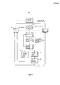
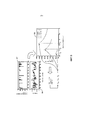
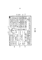
фиг.1 - иллюстративная логическая блок-схема одного варианта осуществления настоящего изобретения;1 is an illustrative logical block diagram of one embodiment of the present invention;
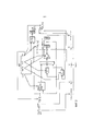
фиг.2 - упрощенная используемая модель поезда;figure 2 is a simplified used model of the train;
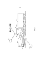
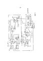
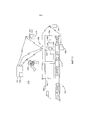
фиг.3 - иллюстративный вариант осуществления элементов настоящего изобретения;figure 3 is an illustrative embodiment of the elements of the present invention;
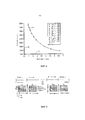
фиг.4 - иллюстративный вариант осуществления кривой расхода топлива/времени движения;4 is an illustrative embodiment of a fuel consumption / travel time curve;
фиг.5 - иллюстративный вариант осуществления разбиения на участки для планирования поездки;5 is an illustrative embodiment of the implementation of the division into sections for planning a trip;
фиг.6 - иллюстративный вариант осуществления примера разбиения;6 is an illustrative embodiment of an example partition;
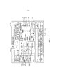
фиг.7 - иллюстративная логическая блок-схема одного варианта осуществления настоящего изобретения;7 is an illustrative logical block diagram of one embodiment of the present invention;
фиг.8 - иллюстрация динамического дисплея для использования машинистом;Fig. 8 is an illustration of a dynamic display for use by a driver;
фиг.9 - другая иллюстрация динамического дисплея для использования машинистом;Fig.9 is another illustration of a dynamic display for use by a driver;
фиг.10 - еще одна иллюстрация динамического дисплея для использования машинистом;figure 10 is another illustration of a dynamic display for use by the driver;
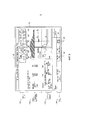
фиг.11 - схема системы для автоматического определения параметров вагона, используемых для улучшения работы поезда; и11 is a diagram of a system for automatically determining the parameters of a car used to improve the operation of a train; and
фиг.12 - логическая блок-схема способа автоматического определения параметров вагона, используемых для улучшения работы поезда.12 is a logical flowchart of a method for automatically determining car parameters used to improve train operation.
Иллюстративные варианты осуществления настоящего изобретения решают проблемы, свойственные уровню техники, за счет обеспечения системы, способа и компьютерного программного кода для определения параметров вагона, используемых для улучшения работы поезда. Специалистам в данной области техники очевидно, что устройство, например система обработки данных, включающее в себя ЦП, память, устройство ввода/вывода, хранилище программ, шину обмена данными и другие необходимые компоненты, можно запрограммировать или иначе приспособить для реализации способа согласно вариантам осуществления настоящего изобретения. Такая система включает в себя соответствующее программное средство для выполнения способов согласно этим вариантам осуществления.Illustrative embodiments of the present invention solve the problems inherent in the prior art by providing a system, method and computer program code for determining car parameters used to improve train operation. It will be apparent to those skilled in the art that a device, such as a data processing system, including a CPU, memory, an input / output device, program storage, data bus, and other necessary components, can be programmed or otherwise adapted to implement the method according to embodiments of the present inventions. Such a system includes appropriate software for executing methods according to these embodiments.
В широком смысле изобретение позволяет определять параметры вагона и использовать эти параметры для улучшения работы поезда. Изобретение описано в общем контексте компьютерно-выполняемых команд, например программных модулей, выполняемых компьютером. В общем случае программные модули включают в себя процедуры, программы, объекты, компоненты, структуры данных и т.д., которые выполняют конкретные задачи или реализуют те или иные абстрактные типы данных. Например, программное обеспечение, лежащее в основе иллюстративных вариантов осуществления настоящего изобретения, может быть написано на разных языках, для использования с разными платформами обработки данных. Однако очевидно, что принципы, лежащие в основе иллюстративных вариантов осуществления настоящего изобретения, можно реализовать посредством других типов компьютерного программного обеспечения.In a broad sense, the invention allows to determine the parameters of the car and use these parameters to improve the operation of the train. The invention is described in the general context of computer-executable instructions, such as program modules, being executed by a computer. In the general case, program modules include procedures, programs, objects, components, data structures, etc. that perform specific tasks or implement particular abstract data types. For example, the software underlying the illustrative embodiments of the present invention may be written in different languages for use with different data processing platforms. However, it is obvious that the principles underlying the illustrative embodiments of the present invention can be implemented by other types of computer software.
Кроме того, специалистам в данной области техники очевидно, что варианты осуществления изобретения можно осуществлять на практике с другими конфигурациями компьютерной системы, включающими в себя карманные устройства, многопроцессорные системы, бытовую электронику на базе микропроцессора или с возможностью программирования, миникомпьютеры, универсальные компьютеры и пр. Варианты осуществления также можно осуществлять на практике в распределенной вычислительной среде, где задания выполняются удаленными устройствами обработки, которые связаны друг с другом сетью связи. В распределенной вычислительной среде программные модули могут размещаться как на локальных, так и на удаленных компьютерных носителях, включающих в себя запоминающие устройства.In addition, it will be apparent to those skilled in the art that embodiments of the invention can be practiced with other computer system configurations, including handheld devices, multiprocessor systems, microprocessor-based consumer electronics, programmable minicomputers, universal computers, etc. Embodiments may also be practiced in a distributed computing environment where tasks are performed by remote processing devices that rye connected with each other communication network. In a distributed computing environment, program modules may be located on both local and remote computer storage media including storage devices.
Кроме того, изделие производства, например записанный диск или другой аналогичный компьютерный программный продукт для использования с системой обработки данных включает в себя носитель данных и записанную на нем программу, предписывающую системе обработки данных выполнять способы настоящего изобретения. Такие устройство и изделия производства также отвечают сущности и объему настоящего изобретения.In addition, a production product, such as a recorded disc or other similar computer program product for use with a data processing system, includes a storage medium and a program recorded thereon instructing the data processing system to perform the methods of the present invention. Such devices and articles of manufacture also meet the essence and scope of the present invention.
В этом документе используется термин локомотивная сцепка. Термин локомотивная сцепка означает один или несколько локомотивов подряд, соединенных друг с другом для обеспечения движущей и/или тормозящей способности. Локомотивы соединены друг с другом так, что между локомотивами нет вагонов поезда. Поезд может содержать одну или несколько локомотивных сцепок. В частности, может иметь место головная сцепка и одна или несколько удаленных сцепок, например первая удаленная сцепка посередине последовательности вагонов и другая удаленная сцепка в хвосте поезда. Каждая локомотивная сцепка может иметь первый или головной локомотив и один или несколько хвостовых локомотивов. Хотя первый локомотив обычно рассматривается как головной локомотив, специалистам в данной области техники очевидно, что первый локомотив в многолокомотивной сцепке может физически размещаться в физически задней позиции. Хотя локомотивная сцепка обычно рассматривается как последовательные локомотивы, специалистам в данной области техники очевидно, что группу локомотивов также можно считать сцепкой даже при наличии, по меньшей мере, одного вагона, разделяющего локомотивы, например, когда локомотивная сцепка предназначена для работы в режиме распределенной подачи мощности, в котором команды ускорения и торможения передаются от головного локомотива на удаленные локомотивы по каналу радиосвязи или физическому кабелю. По этой причине термин локомотивная сцепка не следует считать ограничивающим фактором при рассмотрении множественных локомотивов в одном и том же поезде.The term locomotive coupling is used in this document. The term locomotive coupling means one or more locomotives in a row connected to each other to provide driving and / or braking ability. Locomotives are connected to each other so that there are no train cars between the locomotives. A train may contain one or more locomotive couplings. In particular, there may be a head hitch and one or more remote hitch, for example a first remote hitch in the middle of a train sequence and another remote hitch at the tail of the train. Each locomotive coupling may have a first or lead locomotive and one or more tail locomotives. Although the first locomotive is generally regarded as the lead locomotive, it will be apparent to those skilled in the art that the first locomotive in a multi-locomotive coupling can be physically located in a physically rear position. Although a locomotive coupling is generally regarded as sequential locomotives, it will be apparent to those skilled in the art that a group of locomotives can also be considered a coupling even if there is at least one car separating the locomotives, for example when the locomotive coupling is designed to operate in distributed power mode in which acceleration and braking commands are transmitted from the lead locomotive to remote locomotives via a radio channel or physical cable. For this reason, the term locomotive linkage should not be considered a limiting factor when considering multiple locomotives in the same train.
Перейдем к описанию вариантов осуществления настоящего изобретения со ссылкой на чертежи. Варианты осуществления изобретения можно реализовать по-разному, в том числе в виде системы (включающей в себя компьютерную систему обработки), способа (включающего в себя компьютеризированный способ), устройства, компьютерно-считываемого носителя, компьютерного программного продукта, графического интерфейса пользователя, включающего в себя веб-портал или структуру данных, физически воплощенного в компьютерно-считываемой памяти. Ниже рассмотрено несколько вариантов осуществления настоящего изобретения.Turning to the description of embodiments of the present invention with reference to the drawings. Embodiments of the invention can be implemented in different ways, including in the form of a system (including a computer processing system), a method (including a computerized method), a device, a computer-readable medium, a computer program product, a graphical user interface, including a web portal or data structure physically embodied in computer readable memory. Several embodiments of the present invention are described below.
На фиг.1 представлена иллюстративная логическая блок-схема настоящего изобретения. Показано, что инструкции поступают в соответствии с планированием поездки либо на борту, либо из удаленного положения, например диспетчерского центра 10. Такая входная информация включает в себя, но без ограничения, положение поезда, состав сцепки (например, модели локомотивов), характеристику тяговой мощности локомотива для передачи тяги локомотива, расход топлива как функцию выходной мощности, характеристики охлаждения, назначенный маршрут поездки (эффективный уклон пути и кривизна как функция железнодорожного знака или компонент "эффективного уклона", отражающий кривизну, согласно стандартным железнодорожным принципам), состав и нагрузку вагонов (включая эффективные коэффициенты сопротивления), нужные параметры движения, включающие в себя, но без ограничения, начальные время и положение, конечное положение, время движения, идентификацию бригады (пользователя и/или машиниста), время истечения рабочей смены и маршрут поездки.Figure 1 presents an illustrative logical block diagram of the present invention. It is shown that the instructions come in accordance with the trip planning either on board or from a remote position, for example, the
Эти данные могут поступать на локомотив 42 согласно различным методам и процессам в порядке примера, но не ограничения, посредством ручного ввода машиниста в локомотив 42 через бортовой дисплей, обращения к устройству хранения данных, например ПЗУ, жесткому диску и/или флэш-карте или передачи информации по беспроводному каналу связи из центрального или придорожного положения 41, например путевого сигнального устройства и/или придорожного устройства, на локомотив 42. Характеристики нагрузки локомотива 42 и поезда 31 (например, сопротивление) также могут изменяться на протяжении маршрута (например, в зависимости от высоты, температуры воздуха и состояния рельсов и вагонов), что приводит к обновлению плана, отражающему такие изменения согласно любым рассмотренным выше способам. Обновленные данные, которые влияют на процесс оптимизации движения, могут поступать согласно любым описанным выше способам и методам и/или посредством автономного сбора данных состояния локомотива/поезда в реальном времени. Такие обновления включают в себя, например, изменения характеристик локомотива или поезда, зарегистрированные оборудованием мониторинга на локомотиве 42 или вне его.This data can be transmitted to the locomotive 42 according to various methods and processes by way of example, but not limitation, by manually entering the driver into the locomotive 42 through the on-board display, accessing a storage device, such as a ROM, hard disk and / or flash drive or flash drive information on a wireless communication channel from a central or
Путевая сигнальная система определяет допустимую скорость поезда. Существует много типов путевых сигнальных систем и правил эксплуатации, связанных с каждым из сигналов. Например, некоторые сигналы имеют единичный свет (включаемый/отключаемый), некоторые сигналы имеют единичную линзу с множественными цветами и некоторые сигналы имеют множественные световые сигналы и цвета. Эти сигналы могут указывать, что путь свободен и что поезд может следовать на максимальной допустимой скорости. Они также могут указывать необходимость снижения скорости или остановки. Это снижение скорости может быть необходимо осуществлять незамедлительно или в определенном положении (например, до следующего сигнала или пересечения).The track signal system determines the permissible speed of the train. There are many types of track signaling systems and operating rules associated with each signal. For example, some signals have a single light (on / off), some signals have a single lens with multiple colors, and some signals have multiple light signals and colors. These signals may indicate that the path is clear and that the train can follow at maximum permissible speed. They may also indicate the need to slow down or stop. This speed reduction may be necessary to carry out immediately or in a certain position (for example, until the next signal or crossing).
Состояние сигнала передается на поезд и/или машинисту различными средствами. Некоторые системы имеют схемы на пути и воспринимающие катушки индуктивности на локомотивах. Другие системы имеют беспроводные системы связи. Сигнальные системы также могут требовать, чтобы машинист визуально наблюдал сигнал и предпринимал соответствующие действия.The signal status is transmitted to the train and / or the driver by various means. Some systems have circuits in the path and sensing inductors on locomotives. Other systems have wireless communication systems. Signaling systems may also require the driver to visually observe the signal and take appropriate action.
Сигнальная система может взаимодействовать с бортовой сигнальной системой и регулировать скорость локомотива согласно вводам и соответствующим правилам эксплуатации. Для сигнальных систем, требующих, чтобы машинист визуально наблюдал состояние сигнала, на экране машиниста представлены соответствующие варианты сигнала, которые машинист должен вводить на основании положения поезда. Тип сигнальных систем и правил эксплуатации, как функция положения, может храниться в бортовой базе данных 63.The signal system can interact with the on-board signal system and adjust the speed of the locomotive according to the inputs and relevant operating rules. For signal systems that require the driver to visually observe the state of the signal, the driver displays the corresponding signal options that the driver should enter based on the position of the train. The type of signaling systems and operating rules, as a function of position, can be stored in the on-
На основании данных спецификации, вводимых в иллюстративный вариант осуществления настоящего изобретения, вычисляется оптимальный план, который минимизирует расход топлива и/или генерацию выбросов с учетом предельной скорости вдоль маршрута и нужных начального и конечного времени для создания профиля поездки 12. Профиль содержит регулировки оптимальной скорости и мощности (позиции регулятора), которым должен следовать поезд, выраженные как функция расстояния и/или времени от начала движения, эксплуатационные ограничения поезда, включающие в себя, но без ограничения, регулировки максимальной мощности в соответствии с позицией регулятора и торможения, предельные скорости как функция положения и предполагаемые расход топлива и генерацию выбросов. Согласно иллюстративному варианту осуществления значение позиции регулятора выбирается для получения решения на переключение регулятора примерно через каждые 10-30 секунд. Специалистам в данной области техники очевидно, что решения на переключение регулятора можно получать с более длинными или более короткими интервалами, если необходимо и/или желательно следовать оптимальному профилю скорости. В более широком смысле специалистам в данной области техники очевидно, что профили обеспечивают регулировки мощности для поезда, на уровне поездов на уровне сцепок и/или на уровне отдельных локомотивов. Используемое здесь понятие мощности содержит тормозную мощность, движущую мощность и мощность пневматических тормозов. Согласно другому предпочтительному варианту осуществления вместо работы с традиционными дискретными позициями регулятора мощности настоящее изобретение определяет нужную регулировку мощности из непрерывного диапазона регулировок мощности для оптимизации профиля скорости. Таким образом, например, если оптимальный профиль указывает позицию регулятора 6.8 вместо позиции регулятора 7, локомотив 42 работает на 6.8. Благодаря таким промежуточным регулировкам мощности можно обеспечить дополнительный выигрыш в эффективности, как будет описано далее.Based on the specification data introduced in the illustrative embodiment of the present invention, an optimal plan is calculated that minimizes fuel consumption and / or emission generation taking into account the speed limit along the route and the required start and end times to create a
Процедура вычисления оптимального профиля может включать в себя разнообразные способы расчета последовательности подачи мощности, которая движет поезд 31, для минимизации расхода топлива и/или выбросов при условии эксплуатационных ограничений и ограничений, налагаемых расписанием, для локомотива, которые приведены ниже. В ряде случаев оптимальный профиль может быть, по существу, аналогичен ранее определенному профилю в силу схожести конфигураций поезда, маршрута и условий окружающей среды. В этих случаях может быть достаточно извлечь предварительно определенный режим управления из базы данных 63 и управлять поездом в соответствии с ним. В отсутствие предыдущего плана, способы вычисления нового плана включают в себя, но без ограничения, прямое вычисление оптимального профиля с использованием моделей на основе дифференциальных уравнений, которые аппроксимируют физику движения поезда. Согласно этому процессу определяется количественная целевая функция, причем функция обычно содержит взвешенную сумму (интеграл) модельных переменных, которые соответствуют скорости расхода топлива и генерации выбросов плюс член, наказывающий за чрезмерное переключение регулятора.The procedure for calculating the optimal profile may include a variety of methods for calculating the sequence of power supply that the
Формула оптимального управления устанавливается для минимизации количественной целевой функции при условии ограничений, включающих в себя, но без ограничения, регулировки предельной скорости и минимальной и максимальной мощности (положения регулятора). В зависимости от задач планирования в любое время задача может ставиться гибко, чтобы минимизировать топливо при условии ограничений на выбросы и предельные скорости или чтобы минимизировать выбросы, при условии ограничений на расход топлива и время прибытия. Можно также поставить целью, например, минимизировать суммарное время движения без ограничений на совокупные выбросы или расход топлива, когда такое смягчение ограничений разрешено или необходимо для рейса.The optimal control formula is established to minimize the quantitative objective function, subject to restrictions including, but not limited to, regulation of the maximum speed and minimum and maximum power (position of the controller). Depending on the planning tasks, at any time the task can be set flexibly to minimize fuel, subject to emission limits and speed limits, or to minimize emissions, subject to restrictions on fuel consumption and arrival time. You can also set a goal, for example, to minimize the total travel time without restrictions on total emissions or fuel consumption, when such mitigation of restrictions is allowed or necessary for the flight.
В этом документе представлены иллюстративные уравнения и целевые функции для минимизации расхода топлива локомотива. Эти уравнения и функции приведены исключительно в порядке примера, поскольку другие уравнения и целевые функции можно применять для оптимизации расхода топлива или для оптимизации других рабочих параметров локомотива/поезда.This document provides illustrative equations and objective functions to minimize locomotive fuel consumption. These equations and functions are given solely by way of example, since other equations and objective functions can be used to optimize fuel consumption or to optimize other operating parameters of a locomotive / train.
Математически задачу, подлежащую решению, можно поставить более точно. Основные физические процессы выражаются следующим образом:Mathematically, the problem to be solved can be posed more accurately. The basic physical processes are expressed as follows:

где x - положение поезда, v - скорость поезда, t - время (в милях, милях в час и минутах или часах, соответственно) и u - входная команда позиции регулятора (мощности). Кроме того, D обозначает расстояние, которое необходимо преодолеть, T f - нужное время прибытия на расстоянии D вдоль пути, T e - тяговое усилие, развиваемое локомотивной сцепкой, G a - гравитационное сопротивление, которое зависит от длины поезда, состава поезда и местности, в которой находится поезд, и R - чистое сопротивление, зависящее от скорости, комбинации локомотивной сцепки и поезда. Также можно задать начальную и конечную скорости, но без потери общности, здесь они заданы равными нулю (поезд стоит в начале и конце поездки). Модель легко модифицировать, включая в нее другие динамические факторы, например задержку между переключением регулятора, u, изменением тягового или тормозящего усилия. С использованием этой модели устанавливается формула оптимального управления для минимизации количественной целевой функции при условии ограничений, включающих в себя, но без ограничения, предельные скорости и минимальную и максимальную регулировки мощности (положения регулятора). В зависимости от задачи планирования в любое время задача может быть задана гибко для минимизации расхода топлива при условии ограничений на выбросы и предельных скоростей или для минимизации выбросов, при условии ограничений на расход топлива и время прибытия.where x is the position of the train, v is the speed of the train, t is time (in miles, miles per hour and minutes or hours, respectively) and u is the input command for the position of the controller (power). In addition, D denotes the distance that must be covered, T f is the required arrival time at a distance D along the path, T e is the traction force developed by the locomotive coupling, G a is the gravitational resistance, which depends on the length of the train, train composition and terrain, where the train is located, and R is the net drag, depending on speed, a combination of locomotive coupling and train. You can also set the initial and final speeds, but without loss of generality, here they are set equal to zero (the train is at the beginning and end of the trip). The model is easy to modify, including other dynamic factors, for example, the delay between switching the regulator, u , a change in traction or braking force. Using this model, an optimal control formula is established to minimize the quantitative objective function, subject to restrictions that include, but are not limited to, maximum speeds and minimum and maximum power adjustments (controller positions). Depending on the planning task, at any time the task can be set flexibly to minimize fuel consumption, subject to emission limits and speed limits, or to minimize emissions, subject to restrictions on fuel consumption and arrival time.
Также можно задать целью, например, минимизацию суммарного времени движения без ограничений на совокупные выбросы или расход топлива в случае, когда такое ослабление ограничений разрешено или необходимо для рейса. Все эти рабочие характеристики можно выразить как линейную комбинацию любых из следующих величин:You can also set a goal, for example, to minimize the total travel time without restrictions on total emissions or fuel consumption in the case when such a relaxation of restrictions is allowed or necessary for the flight. All of these performance characteristics can be expressed as a linear combination of any of the following values:

![]()
![]()
![]()
![]()
![]()
![]()
Замена топливного члена F(·) в (1) членом, соответствующим выработке выбросов. Например, для выбросов 
Таким образом, широко используемая иллюстративная целевая функция имеет видThus, the widely used illustrative objective function has the form
![]()
![]()
Коэффициенты линейной комбинации зависят от важности (веса), присвоенной каждому члену. Заметим, что в уравнении (OP) u(t) - оптимизирующая переменная, т.е. непрерывная позиция регулятора. Если требуется дискретная позиция регулятора, например для более старых локомотивов, решение уравнения (OP) дискретизируется, что может приводить с снижению экономии топлива. Отыскание решения минимального времени (α1 задан равным нулю и α2 задан равным нулю или относительно малой величиной) используется для нахождения нижней границы достижимого времени движения (T f=T fmin). В этом случае u(t) и T f являются оптимизирующими переменными. Предпочтительный вариант осуществления предусматривает решение уравнения (OP) для различных значений T f при T f > T fmin с α3, заданным равным нулю. В этом последнем случае T f рассматривается как ограничение.The linear combination coefficients depend on the importance (weight) assigned to each member. Note that in equation (OP) u ( t ) is an optimizing variable, i.e. continuous position of the regulator. If a discrete controller position is required, for example for older locomotives, the solution of the equation (OP) is discretized, which can lead to lower fuel economy. Finding the solution of the minimum time (α 1 is set equal to zero and α 2 is set equal to zero or a relatively small value) is used to find the lower boundary of the attainable travel time ( T f = T fmin ). In this case, u ( t ) and T f are optimizing variables. A preferred embodiment provides a solution to the equation (OP) for various values of T f at T f > T fmin with α 3 set to zero. In this latter case, T f is considered as a limitation.
Для тех, кто знаком с решениями таких задач оптимизации, могут потребоваться граничные условия, например, для предельной скорости вдоль пути:For those who are familiar with the solutions of such optimization problems, boundary conditions may be required, for example, for the maximum speed along the path:
![]()
![]()
или, если целью является достижение минимального времени, должно выполняться граничное условие, например, полный расход топлива должен быть меньше объема топливного бака, например, в виде:or, if the goal is to achieve a minimum time, the boundary condition must be fulfilled, for example, the total fuel consumption should be less than the volume of the fuel tank, for example, in the form of:

где W F - топливо, оставшееся в баке на момент T f. Специалистам в данной области техники очевидно, что уравнение (OP) можно представить в других формах и что вышеприведенная версия является иллюстративным уравнением для использования согласно вариантам осуществления настоящего изобретения.where W F is the fuel remaining in the tank at the time T f . Those skilled in the art will appreciate that the equation (OP) can be presented in other forms and that the above version is an illustrative equation for use in accordance with embodiments of the present invention.
Под выбросами в контексте настоящего изобретения в общем случае подразумевается совокупная генерация выбросов в различных формах. Например, требования к выбросам могут задавать максимальное значение выбросов оксида азота (NOx), выбросов углеводородов (HC), выбросов оксида углерода (COx) и/или выбросов твердых частиц (PM). Другие ограничения по выбросам могут включать в себя максимальное значение электромагнитного излучения, например предельный выход радиочастотной (RF) мощности, измеряемый в ваттах, на соответствующих частотах, излучаемых локомотивом. Еще одной формой выбросов является шум, производимый локомотивом, обычно измеряемый в децибелах (дБ). Требования к выбросам могут изменяться в зависимости от времени суток, времени года и/или атмосферных условий, например, погоды или уровня загрязненности атмосферы. Известно, что требования к выбросам могут изменяться географически по железнодорожной системе. Например, рабочая область, например, город или штат могут иметь указанные требования к выбросам, и соседняя рабочая область может иметь другие требования к выбросам, например меньшее количество допустимых выбросов или более высокую плату, взимаемую за данный уровень выбросов. Соответственно, профиль выбросов для определенной географической области можно регулировать так, чтобы он включал в себя максимальные значения выбросов для каждого вида выбросов, подчиняющегося законодательству, включенного в профиль для удовлетворения заранее определенным требованиям к выбросам, установленным в этой области. Обычно для локомотива эти параметры выбросов определяются мощностью (позицией регулятора), условиями окружающей среды, способом управления двигателем и т.д.Emissions in the context of the present invention generally means the cumulative generation of emissions in various forms. For example, emission requirements can set a maximum value for emissions of nitric oxide (NO x ), emissions of hydrocarbons (HC), emissions of carbon monoxide (CO x ) and / or emissions of particulate matter (PM). Other emission limits may include the maximum value of electromagnetic radiation, for example the maximum output of radio frequency (RF) power, measured in watts, at the corresponding frequencies emitted by the locomotive. Another form of emissions is the noise produced by a locomotive, usually measured in decibels (dB). Emission requirements may vary depending on the time of day, time of year and / or atmospheric conditions, for example, weather or the level of air pollution. It is known that emission requirements can vary geographically across the railway system. For example, a work area, such as a city or state, may have specified emission requirements, and a neighboring work area may have other emission requirements, such as fewer allowable emissions or a higher charge for a given level of emissions. Accordingly, the emission profile for a specific geographical area can be adjusted so that it includes the maximum emission values for each type of emission that is subject to the legislation included in the profile to meet the predetermined emission requirements established in this area. Typically for a locomotive, these emission parameters are determined by power (controller position), environmental conditions, engine control method, etc.
Конструкция каждого локомотива должна соответствовать стандартам выбросов EPA для выбросов, определяемых торможением, и, таким образом, при оптимизации выбросов согласно иллюстративному варианту осуществления настоящего изобретения это будут совокупные выбросы рейса, на которые в настоящее время нет технических условий. Работа локомотива согласно оптимизированному плану поездки в любое время согласуется со стандартами выбросов EPA. Если основной задачей в ходе поездки является сокращение выбросов, формула оптимального управления, уравнение (OP), видоизменяется с учетом этого требования к поездке. Принципиальная изменчивость процесса оптимизации состоит в том, что любые или все требования к поездке могут изменяться в зависимости от географической области или рейса. Например, для поезда с высоким приоритетом, минимальное время может быть единственным требованием на одном маршруте в силу приоритета поезда. В другом примере выбросы могут изменяться от состояния к состоянию вдоль запланированного маршрута поезда.The design of each locomotive must comply with EPA emission standards for emissions determined by braking, and thus, when optimizing emissions according to an illustrative embodiment of the present invention, these will be cumulative flight emissions for which there are currently no specifications. The operation of the locomotive according to the optimized travel plan is at any time consistent with EPA emission standards. If the main objective during the trip is to reduce emissions, the optimal control formula, the equation (OP), is modified taking into account this travel requirement. The fundamental variability of the optimization process is that any or all travel requirements may vary depending on geographic area or flight. For example, for a train with a high priority, the minimum time may be the only requirement on one route due to the priority of the train. In another example, emissions may vary from state to state along a train's planned route.
Для решения результирующей задачи оптимизации, согласно иллюстративному варианту осуществления, настоящее изобретение предусматривает преобразование динамической задачи оптимизации управления во временном измерении в эквивалентную статическую задачу математического программирования с N искомыми переменными, где число 'N' зависит от частоты, с которой перемещают рычаги регулятора и тормоза, и от продолжительности поездки. Для типичных задач N может составлять тысячи. Согласно иллюстративному варианту осуществления поезд движется по 172-мильному участку пути на юго-западе США. С использованием настоящего изобретения можно реализовать иллюстративную 7,6% экономию расхода топлива по сравнению с поездкой, определенной и выполняемой согласно аспектам настоящего изобретения, в отличие от поездки, где положение регулятора/скорость определяет машинист согласно стандартной практике. Повышенная экономия реализуется благодаря оптимизации, достигаемой с использованием иллюстративного варианта осуществления настоящего изобретения, который позволяет вырабатывать стратегию управления, отличающуюся как более низкими потерями на сопротивление, так и малыми или отсутствующими потерями на торможение по сравнению с планом поездки машиниста.To solve the resulting optimization problem, according to an illustrative embodiment, the present invention provides for the conversion of a dynamic control optimization problem in time dimension to an equivalent static mathematical programming problem with N desired variables, where the number ' N ' depends on the frequency with which the control levers and brakes are moved, and on the duration of the trip. For typical tasks, N can be thousands. In an exemplary embodiment, the train travels along a 172-mile stretch of track in the southwestern United States. Using the present invention, it is possible to realize an illustrative 7.6% fuel economy compared to a trip defined and performed according to aspects of the present invention, as opposed to a trip where the position of the governor / speed is determined by the driver according to standard practice. Increased savings are realized due to the optimization achieved using an illustrative embodiment of the present invention, which allows to develop a control strategy that is characterized by both lower resistance losses and low or no braking losses compared to the driver’s travel plan.
Чтобы сделать вышеописанную оптимизацию вычислительно пригодной, можно применять упрощенную модель поезда, например, показанную на фиг.2 и представленную рассмотренными выше уравнениями. Принципиальное улучшение оптимального профиля достигается за счет вывода более подробной модели с генерацией оптимальной последовательностью подачи мощности для проверки, нарушаются ли какие-либо тепловые, электрические и механические ограничения, что приводит к изменению профиля скорости в зависимости от расстояния, которому можно следовать, которого можно добиться без повреждения оборудования локомотива или поезда, т.е. удовлетворяя дополнительно налагаемым ограничениям, например тепловым или электрическим ограничениям на локомотив и внутрипоездные силы.In order to make the optimization described above computationally suitable, a simplified train model can be used, for example, as shown in FIG. 2 and represented by the above equations. A fundamental improvement in the optimal profile is achieved by deriving a more detailed model with the generation of an optimal power supply sequence to check whether any thermal, electrical and mechanical restrictions are violated, which leads to a change in the velocity profile depending on the distance that can be followed, which can be achieved without damaging the equipment of the locomotive or train, i.e. satisfying additionally imposed restrictions, for example, thermal or electrical restrictions on the locomotive and the train forces.
Согласно фиг.1, когда поездка начинается 12, команды подачи мощности генерируются 14 для начала исполнения плана. В зависимости от рабочих настроек иллюстративного варианта осуществления настоящего изобретения одна команда предписывает локомотиву выполнять оптимизированную команду подачи мощности 16 для достижения оптимальной скорости. Один вариант осуществления предусматривает получение информации фактической скорости и мощности от локомотивной сцепки поезда 18. В силу общих приближений в моделях, используемых для оптимизации, получается вычисление по замкнутому циклу корректировок оптимизированной мощности для следования нужной оптимальной скорости. Такие корректировки эксплуатационных ограничений поезда могут производиться автоматически или машинистом, который всегда имеет полный контроль над поездом.1, when the trip starts 12, power supply commands are generated 14 to start executing the plan. Depending on the operating settings of an illustrative embodiment of the present invention, one command instructs the locomotive to execute an optimized
В ряде случаев модель, используемая для оптимизации, может значительно отличаться от фактического поезда. Это может происходить по многим причинам, включая, но без ограничения, дополнительные погрузочно-разгрузочные операции, поломки локомотивов в пути, ошибки в первоначальной базе данных 63 и ошибки машиниста при вводе данных. По этим причинам система мониторинга использует данные поезда в реальном времени для оценивания параметров локомотива и/или поезда в реальном времени 20. Оцененные параметры сравниваются с предполагаемыми параметрами при первоначальном создании 22 поездки. На основании любых различий между предполагаемыми и оцененными значениями, поезду можно повторно планировать 24. Обычно поездка повторно планируется, если новый план позволяет обеспечить значительную экономию.In some cases, the model used for optimization may differ significantly from the actual train. This can happen for many reasons, including, but not limited to, additional loading and unloading operations, breakdowns of locomotives along the way, errors in the
Другие причины, почему поездка может быть повторно запланирована, включают в себя директивы из удаленного положения, напримерот диспетчера, и/или запрос машиниста на изменение требований в соответствии с глобальными задачами планирования движения. Такие глобальные задачи планирования движения могут включать в себя, но без ограничения, графики других поездов, время, необходимое на рассеяние выхлопных газов в туннеле, операции обслуживания и т.д. Еще одной причиной может быть отказ бортового компонента. Стратегии повторного планирования можно группировать в возрастающие и основные корректировки в зависимости от серьезности нарушения, что рассмотрено более подробно ниже. В общем случае, "новый" план нужно выводить из вышеописанного решения задачи оптимизации уравнения (OP), но зачастую можно находить более быстрые приближенные решения, которые описаны здесь.Other reasons why the trip may be re-planned include directives from a remote location, such as from a dispatcher, and / or requesting the driver to change requirements in accordance with global traffic planning tasks. Such global traffic planning tasks may include, but are not limited to, schedules of other trains, the time required to disperse the exhaust gases in the tunnel, maintenance operations, etc. Another reason could be a failure of the airborne component. Re-planning strategies can be grouped into incremental and major adjustments depending on the severity of the violation, which is discussed in more detail below. In the general case, the “new” plan needs to be derived from the above solution of the equation optimization problem (OP), but often faster approximate solutions can be found that are described here.
В ходе работы локомотив 42 непрерывно отслеживает эффективность системы и непрерывно обновляет план поездки на основании фактической измеренной эффективности всякий раз, когда такое обновление повышает характеристики поездки. Расчеты повторного планирования можно производить целиком на локомотиве, или полностью, или частично в удаленном положении, например в диспетчерской службе или придорожных устройствах обработки, где беспроводная технология позволяет передавать новый план на локомотив 42. Один вариант осуществления настоящего изобретения также предполагает генерацию тенденций эффективности для генерации данных локомотивного парка, касающихся функций переноса эффективности. Данные, относящиеся к парку, можно использовать при определении первоначального плана поездки и можно использовать для компромиссной оптимизации в масштабе сети с учетом положений совокупности поездов. Например, компромиссная кривая - время движения/расход топлива, показанная на фиг.4, отражает возможности поезда на конкретном маршруте в данное время, обновленные относительно средних по ансамблю, собранных из многочисленных аналогичных поездов на том же маршруте. Таким образом, центральная диспетчерская служба, собирающая кривые наподобие показанной на фиг.4, от многочисленных локомотивов, может использовать эту информацию для улучшения координации движения всех поездов для достижения преимущества в расходе топлива или пропускной способности в масштабе системы.During operation, the locomotive 42 continuously monitors the effectiveness of the system and continuously updates the travel plan based on the actual measured efficiency whenever such an update improves the performance of the trip. The re-planning calculations can be performed entirely on the locomotive, or in whole or in part in a remote position, for example, in a dispatching service or roadside processing devices, where wireless technology allows the transfer of a new plan to the locomotive 42. One embodiment of the present invention also involves generating performance trends for generation locomotive fleet data regarding performance transfer functions. The data related to the park can be used to determine the initial travel plan and can be used for compromise network-wide optimization, taking into account the provisions of the train population. For example, a compromise curve - travel time / fuel consumption, shown in figure 4, reflects the capabilities of the train on a particular route at a given time, updated relative to the ensemble average collected from numerous similar trains on the same route. Thus, a central dispatch service collecting curves like the one shown in FIG. 4 from multiple locomotives can use this information to improve coordination of all trains to achieve an advantage in fuel consumption or system-wide capacity.
Многие события в каждодневной работе могут приводить к необходимости создавать или изменять существующий план, когда желательно сохранять одни и те же требования к поездке, на случай, когда поезд отклоняется от расписания для запланированной встречи или обхода с другим поездом, и для этого требуется выделять время. С использованием фактических скорости, мощности и положения локомотива, запланированное время прибытия сравнивается с оцененным на данный момент (прогнозируемым) временем 25 прибытия. На основании разницы во времени, а также различия в параметрах (регистрируемых или изменяемых диспетчером или машинистом) план корректируется 26. Эта корректировка может производиться автоматически на основании политики железнодорожной компании по обработке отступлений от плана или вручную, когда машинист поезда и диспетчер совместно ищут наилучший подход к возвращению к плану. Всякий раз, когда план обновляется, но при этом исходные требования, в порядке примера, но не ограничения, время прибытия, остаются неизменными, дополнительные изменения одновременно можно учитывать например, новые будущие изменения предельной скорости, которые повлияют на возможность возвращения к исходному плану. В таких случаях, если исходный план поездки невозможно поддерживать, или, иными словами, поезд не способен отвечать требованиям исходного плана поездки, согласно приведенному здесь рассмотрению, машинисту, удаленной службе и/или диспетчеру можно представить другой план поездки.Many events in everyday work can lead to the need to create or modify an existing plan when it is desirable to maintain the same travel requirements, in case the train deviates from the schedule for a planned meeting or detour with another train, and this requires time. Using the actual speed, power and position of the locomotive, the planned arrival time is compared with the currently estimated (predicted)
Повторное планирование также можно производить, когда желательно изменить исходные требования. Такое повторное планирование можно осуществлять в определенные моменты времени для повторного планирования, вручную по решению машиниста или диспетчера, или автономно, в случае превышения заданных пределов, например эксплуатационных ограничений поезда. Например, если выполнение текущего плана опаздывает свыше указанного порога, например тридцати минут, один вариант осуществления настоящего изобретения предусматривает повторное планирование поездки для компенсации задержки ценой увеличения расхода топлива, как описано выше, либо для оповещения машиниста и диспетчера, в какой степени потерянное время можно наверстать, если вообще это возможно (т.е. каково оставшееся минимальное время или максимальное количество топлива, которое можно сэкономить при временном ограничении). Другие условия для осуществления повторного планирования также можно предусмотреть на основании расхода топлива или работоспособности тяговой сцепки, включающей в себя, но без ограничения, время прибытия, потерю мощности вследствие отказа оборудования и/или временного сбоя в работе оборудования (например, чрезмерного повышения или понижения рабочей температуры), и/или обнаружения грубых ошибок в настройках, например в расчетной нагрузке поезда. Таким образом, если изменение отражает ухудшение работы локомотива в текущей поездке, их можно вносить в модели и/или уравнения, используемые в процессе оптимизации.You can also re-plan when it is desired to change the initial requirements. Such re-planning can be carried out at certain points in time for re-planning, manually according to the decision of the driver or dispatcher, or autonomously, if specified limits are exceeded, for example, operational restrictions of the train. For example, if the execution of the current plan is late beyond a specified threshold, for example thirty minutes, one embodiment of the present invention provides for re-planning the trip to compensate for the delay by the increase in fuel consumption, as described above, or to notify the driver and dispatcher to what extent the lost time can be made up if at all possible (i.e. what is the remaining minimum time or the maximum amount of fuel that can be saved with a time limit). Other conditions for re-planning can also be provided based on fuel consumption or the performance of the traction coupling, which includes, but is not limited to, arrival time, loss of power due to equipment failure and / or temporary equipment malfunction (for example, excessive increase or decrease in operating temperature), and / or detection of gross errors in the settings, for example, in the design load of the train. Thus, if the change reflects the deterioration of the locomotive in the current trip, they can be introduced into the models and / or equations used in the optimization process.
Изменение требований к плану также может быть обусловлено необходимостью координировать события, когда план для одного поезда снижает способность другого поезда отвечать требованиям и требуется принятие решения на другом уровне, например в диспетчерском центре. Например, координацию встреч и обходов можно дополнительно усовершенствовать за счет связи между поездами. Таким образом, например, если машинист знает, что он отстает от расписания в достижении положения встречи и/или обхода, передачи с другого поезда могут консультировать машиниста опаздывающего поезда (и/или диспетчера). Машинист может вводить информацию, относящуюся к ожидаемой задержке прибытия для повторного вычисления плана поездки поезда. Иллюстративный вариант осуществления также можно использовать на высоком уровне или на уровне сети, чтобы диспетчер мог определить, какой поезд должен снизить или повысить скорость в случае, когда запланированное ограничение времени встречи и/или обхода не может быть выполнено. Согласно приведенному здесь рассмотрению это осуществляется за счет того, что поезда передают данные диспетчеру для принятия решения, как каждый поезд должен изменить свою задачу планирования. Выбор можно делать либо на основании расписания, либо экономии топлива, в зависимости от ситуации.Changes in the requirements for the plan can also be caused by the need to coordinate events when the plan for one train reduces the ability of the other train to meet the requirements and decision is required at a different level, for example, in a control center. For example, coordination of meetings and detours can be further improved through communication between trains. Thus, for example, if the driver knows that he is behind schedule in reaching the meeting and / or bypass position, transfers from another train can be advised by the train operator of the late train (and / or dispatcher). The driver can enter information regarding the expected arrival delay to re-calculate the train travel plan. An exemplary embodiment can also be used at a high level or at a network level, so that the dispatcher can determine which train should slow down or increase speed when the planned time limit for meeting and / or bypass cannot be met. According to the discussion given here, this is due to the fact that the trains transmit data to the dispatcher to decide how each train should change its planning task. The choice can be made either on the basis of a schedule or fuel economy, depending on the situation.
Для любого повторного планирования, инициируемого вручную или автоматически, иллюстративные варианты осуществления настоящего изобретения могут представлять машинисту более одного плана поездки. Согласно иллюстративному варианту осуществления настоящее изобретение представляет машинисту разные профили, позволяя машинисту выбирать время прибытия, а также понимать соответствующее влияние топлива и/или выбросов. Такая информация также может предоставляться диспетчеру по аналогичным соображениям либо в виде простого списка альтернатив, либо в виде совокупности компромиссных кривых, например, показанных на фиг.4.For any re-planning initiated manually or automatically, illustrative embodiments of the present invention may provide the driver with more than one travel plan. According to an illustrative embodiment, the present invention provides the driver with different profiles, allowing the driver to select the arrival time and also to understand the corresponding effect of fuel and / or emissions. Such information can also be provided to the dispatcher for similar reasons, either as a simple list of alternatives, or as a set of compromise curves, for example, shown in Fig.4.
Согласно одному варианту осуществления настоящее изобретение включает в себя способность обучаться и адаптироваться к основным изменениям в поезде и тяговой сцепке, которые могут включаться либо в текущий план и/или в будущие планы. Например, одним из рассмотренных выше инициирующих условий является потеря мощности. При нарастании мощности со временем, либо после потери мощности, либо в начале движения, используется логика переходов для определения, когда будет достигнута нужная мощность. Эта информация может сохраняться в базе 61 данных локомотива для использования при оптимизации либо будущих поездок, либо текущей поездки, если потеря мощности произойдет позже.According to one embodiment, the present invention includes the ability to learn and adapt to major changes in the train and traction coupling, which may be included in either the current plan and / or future plans. For example, one of the initiating conditions discussed above is power loss. When power increases over time, either after power loss, or at the beginning of the movement, the transition logic is used to determine when the desired power will be reached. This information can be stored in the locomotive database 61 for use in optimizing either future trips or the current trip if power loss occurs later.
На фиг.3 показан иллюстративный вариант осуществления элементов настоящего изобретения. Локационный элемент 30 определяет положение поезда 31. Локационный элемент 30 содержит датчик или систему датчиков GPS, которые определяют положение поезда 31. Примеры таких других систем могут включать в себя, но без ограничения, придорожные устройства, например метки радиочастотной автоматической идентификации оборудования (RF AEI), диспетчер и/или определения на основе видеозаписи. Другая система может использовать тахометр(ы) на локомотиве и вычисления расстояния от опорной точки. Согласно вышеприведенному рассмотрению, может быть обеспечена система беспроводной связи 47 для осуществления связи между поездами и/или с удаленным положением, например диспетчером. Информация о положении поезда также может передаваться с других поездов по системе связи.Figure 3 shows an illustrative embodiment of the elements of the present invention. The
Элемент 33 описания пути обеспечивает информацию о пути, в основном информацию уклона, возвышения и кривизны. Элемент 33 описания пути может включать в себя бортовую базу 36 данных целостности пути. Датчики 38 измеряют тяговое усилие 40, развиваемое локомотивной сцепкой 42, положение рукоятки регулятора локомотивной сцепки 42, информацию конфигурации локомотивной сцепки 42, скорость локомотивной сцепки 42, конфигурацию отдельных локомотивов, возможности отдельных локомотивов и т.д. Согласно иллюстративному варианту осуществления информация конфигурации локомотивной сцепки 42 может загружаться без использования датчика 38, но вводится иными средствами, как рассмотрено выше. Кроме того, можно учитывать работоспособность локомотивов в сцепке. Например, если один локомотив в сцепке не способен развивать мощность выше 5 позиции регулятора, эта информация используется при оптимизации плана поездки.The
Информацию от локационного элемента также можно использовать для определения надлежащего времени прибытия поезда 31. Например, если имеется поезд 31, движущийся вдоль пути 34 к пункту назначения, и позади него нет поездов, и поезд не имеет фиксированного предельного времени прибытия, локационный элемент, включающий в себя, но без ограничения, метки радиочастотной автоматической идентификации оборудования (RF AEI), диспетчер и/или определения на основе видеозаписи, можно использовать для определения точного положения поезда 31. Кроме того, вводы из этих сигнальных систем можно использовать для корректировки скорости поезда. Используя бортовую базу данных целостности пути, рассмотренную ниже, и локационный элемент, например GPS, один вариант осуществления настоящего изобретения корректирует интерфейс машиниста, чтобы он отражал состояние сигнальной системы при данном положении локомотива. В случае, когда состояния сигнала указывают недопустимые скорости впереди, планировщик может выбрать замедление поезда для экономии расхода топлива.Information from the location element can also be used to determine the proper arrival time of
Информацию от локационного элемента 30 также можно использовать для изменения задач планирования как функции расстояния до пункта назначения. Например, вследствие неизбежных неопределенностей в отношении затора вдоль маршрута "более быстрые" требования к времени на ранней части маршрута можно применять в качестве защиты от задержек, которые статистически происходят позже. Если в конкретной поездке таких задержек не происходит, требования к более поздней части маршрута можно изменить, чтобы использовать естественный зазор по времени, который накопился ранее, и, таким образом, получить некоторую экономию топлива. Аналогичную стратегию можно применять в отношении требований к ограничению выбросов, например, ограничениям выбросов, которые применяются при приближении к городской области.Information from
В качестве примера защитной стратегии, если поездка запланирована из Нью-Йорка в Чикаго, система может предоставлять возможность вести поезд медленнее в начале поездки, в середине поездки или в конце поездки. Один вариант осуществления настоящего изобретения предусматривает оптимизацию плана поездки, позволяющую снижать скорость в конце поездки, поскольку неизвестные ограничения, в порядке примера, но не ограничения, погодные условия, ремонт пути, и т.д., могут возникнуть и стать известными в ходе поездки. В другом случае, если известны области, где часто случаются заторы, план разрабатывается с возможностью увеличения гибкости управления вокруг таких областей. Таким образом, варианты осуществления настоящего изобретения также могут предусматривать взвешивание/наказание как функцию времени/расстояния в будущем и/или на основании известного/прошлого опыта. Специалистам в данной области техники очевидно, что такое планирование и повторное планирование с учетом погодных условий, состояния пути, наличия других поездов на пути, и т.д. можно рассматривать в любое время в ходе поездки, в котором план поездки соответственно корректируется.As an example of a defensive strategy, if the trip is planned from New York to Chicago, the system may provide the ability to drive the train more slowly at the beginning of the trip, in the middle of the trip, or at the end of the trip. One embodiment of the present invention provides for optimizing the travel plan to reduce speed at the end of the trip, because unknown restrictions, by way of example, but not limitations, weather conditions, track repairs, etc., may occur and become known during the trip. In another case, if areas where congestion often occurs are known, a plan is developed with the possibility of increasing management flexibility around such areas. Thus, embodiments of the present invention may also include weighting / punishment as a function of future time / distance and / or based on known / past experience. Those skilled in the art will appreciate what planning and re-planning is, taking into account weather conditions, the condition of the track, the availability of other trains on the track, etc. can be considered at any time during the trip in which the travel plan is adjusted accordingly.
На фиг.3 дополнительно раскрыты другие элементы, которые могут составлять часть вариантов осуществления настоящего изобретения. Процессор 44 принимает информацию от локационного элемента 30, элемента 33 описания пути и датчиков 38. Алгоритм 46 выполняется на процессоре 44. Алгоритм 46 вычисляет оптимизированный план поездки на основании параметров локомотива 42, поезда 31, пути 34 и требований к рейсу, как описано здесь. Согласно иллюстративному варианту осуществления план поездки устанавливается на основании моделей поведения поезда, когда поезд 31 движется вдоль пути 34 в виде решения нелинейных дифференциальных уравнений, выведенных из применяемой физики с упрощающими гипотезами, которые предусмотрены в алгоритме. Алгоритм 46 имеет доступ к информации из локационного элемента 30, элемента 33 описания пути и/или датчиков 38 для создания плана поездки, минимизирующего расход топлива локомотивной сцепки 42, минимизирующего выбросы локомотивной сцепки 42, устанавливающего нужное время поездки и/или гарантирующего правильное рабочее время бригады на локомотивной сцепке 42. Согласно иллюстративному варианту осуществления предусмотрен также драйвер или элемент управления 51. Согласно приведенному здесь рассмотрению элемент управления 51 может управлять поездом в ходе выполнения плана поездки. Согласно иллюстративному варианту осуществления, рассмотренному далее, элемент управления 51 автономно принимает решения по управлению поездом. Согласно другому иллюстративному варианту осуществления машинист может предписывать поезду следовать плану поездки или отклоняться от него по своему усмотрению.Figure 3 further discloses other elements that may form part of embodiments of the present invention. The
Согласно одному варианту осуществления настоящего изобретения план поездки можно модифицировать в реальном времени по мере выполнения плана. Это изменение включает в себя создание первоначального плана поездки на дальнее расстояние ввиду сложности алгоритма оптимизации плана. Когда полная длина профиля поездки превышает данное расстояние, алгоритм 46 можно использовать для разбиения рейса путем деления рейса на промежуточные пункты. Хотя здесь рассматривается только один алгоритм 46, специалистам в данной области техники очевидно, что можно использовать более одного алгоритма и что такие множественные алгоритмы можно совместно использовать для создания плана поездки. Промежуточные пункты маршрута могут включать в себя естественные положения, где поезд 31 останавливается, в порядке примера, но не ограничения, единичные ответвления магистрали для встречи со встречным движением или для пропускания поезда, идущего позади текущего поезда, сортировочные пути, вспомогательные пути, где вагоны нагружаются и разгружаются, и места запланированных профилактических работ. В таких промежуточных пунктах поезду 31 может потребоваться стоять в течение запланированного времени, останавливаться или двигаться со скоростью в указанном диапазоне. Продолжительность времени от прибытия до отправления в промежуточных пунктах называется временем простоя.According to one embodiment of the present invention, the travel plan can be modified in real time as the plan is completed. This change includes the creation of an initial long-distance travel plan due to the complexity of the plan optimization algorithm. When the total length of the trip profile exceeds a given distance,
Согласно иллюстративному варианту осуществления более длинный маршрут разбивается на более мелкие участки согласно особой системе. Каждый участок может иметь ту или иную длину, но обычно выбирается в естественном положении, например в положении остановки или значительного ограничения по скорости или в положении ключевых промежуточных пунктов или путевых знаков, которые задают соединения с другими маршрутами. При таком выборе отрезков или участков маршрута профиль управления создается для каждого участка пути как функция времени движения, которое рассматривается как независимая переменная, например, как показано на фиг.4. Компромисс расхода топлива/времени движения, связанный с каждым участком, можно вычислять до того, как поезд 31 достигнет этого участка пути. Таким образом, совокупный план поездки можно создавать из профилей управления, созданных для каждого участка. Один вариант осуществления настоящего изобретения предусматривает оптимальное распределение времени движения по всем участкам маршрута, чтобы удовлетворять требованию суммарного времени поездки и минимизировать полный расход топлива на всех участках. Иллюстративный маршрут, состоящий из трех участков, раскрыт на фиг.6 и рассмотрен ниже. Однако специалистам в данной области техники очевидно, что, хотя здесь рассматриваются участки, план поездки может содержать единичный участок, представляющий весь маршрут.According to an illustrative embodiment, the longer route is divided into smaller sections according to a particular system. Each section can be of one or another length, but it is usually chosen in a natural position, for example, in a stop position or a significant speed limit or in the position of key intermediate points or waypoints that define connections with other routes. With this choice of segments or sections of the route, a control profile is created for each section of the path as a function of travel time, which is considered as an independent variable, for example, as shown in FIG. The fuel consumption / travel time tradeoff associated with each leg can be calculated before
На фиг.4 показан иллюстративный вариант осуществления кривой расхода топлива/времени движения. Как отмечено выше, такая кривая 50 создается при вычислении оптимального профиля поездки для различных времен движения для каждого участка. Таким образом, для данного времени движения 51 расход топлива 52 является результатом подробного профиля управления, вычисление которого описано выше. После назначения времени движения для каждого участка план мощности/скорости определяется для каждого участка из предварительно вычисленных решений. При наличии каких-либо ограничений по скорости в промежуточном пункте между участками, в порядке примера, но не ограничения, изменения предельной скорости согласовываются при создании оптимального профиля поездки. Если ограничения по скорости изменяются только на единичном участке, кривую 50 расхода топлива/времени движения нужно повторно вычислить только для участка изменения. Этот процесс сокращает время, необходимое для повторного вычисления большего количества частей, или участков, маршрута. Если локомотивная сцепка или поезд претерпевает значительные изменения вдоль маршрута, например, вследствие потери мощности локомотива, или погрузки, или разгрузки вагонов, то профили управления для всех последующих участков необходимо повторно вычислить для создания новых вариантов кривой 50. Эти новые кривые 50 затем используются совместно с новыми требованиями расписания для планирования оставшейся поездки.FIG. 4 shows an illustrative embodiment of a fuel consumption / travel time curve. As noted above, such a
После создания плана поездки, согласно вышеприведенному рассмотрению, график скорости и мощности в зависимости от расстояния позволяет поезду достигать пункта назначения с минимальным расходом топлива и/или объемом выбросов за необходимое время поездки. Существует несколько методов для выполнения плана поездки. Как описано более подробно ниже, согласно иллюстративному варианту осуществления, в тренировочном режиме, информация отображается машинисту, которой машинист должен руководствоваться для достижения необходимой мощности и скорости, определенной согласно оптимальному плану поездки. В этом режиме эксплуатационная информация представляет собой рекомендованные рабочие состояния, которые машинист должен использовать. Согласно другому иллюстративному варианту осуществления настоящего изобретения осуществляются действия по управлению для ускорения поезда или поддержания постоянной скорости. Однако когда поезд 31 должен замедляться, машинист отвечает за торможение путем управления тормозной системой 52. Согласно другому иллюстративному варианту осуществления обеспечиваются команды разгона и торможения, необходимые для того, чтобы следовать нужному графику скорости-расстояния.After creating a trip plan, according to the above discussion, a graph of speed and power depending on distance allows the train to reach its destination with minimal fuel consumption and / or emissions for the required travel time. There are several methods for implementing a travel plan. As described in more detail below, according to an illustrative embodiment, in a training mode, information is displayed to the driver, which the driver should be guided to achieve the required power and speed, determined according to the optimal travel plan. In this mode, operational information is the recommended operating conditions that the operator should use. According to another exemplary embodiment of the present invention, control actions are taken to accelerate the train or maintain a constant speed. However, when the
Стратегии управления в режиме обратной связи используются для корректировки последовательности управления мощностью в профиле для учета событий, например, но без ограничения, изменений нагрузки поезда, обусловленных изменениями встречного ветра и попутного ветра. Другая подобная ошибка может быть обусловлена ошибкой в параметрах поезда, в порядке примера, но не ограничения, массы поезда и/или сопротивления, в сравнении с предположениями в оптимизированном плане поездки. Третий тип ошибки может иметь место вследствие некорректной информации в базе данных 36 целостности пути. Еще одна возможная ошибка может быть связана с немоделированными изменениями характеристик, связанных с двигателем локомотива, перегревом тягового двигателя и/или другими факторами. Стратегии управления в режиме обратной связи сравнивают фактическую скорость как функцию позиции со скоростью в нужном оптимальном профиле. На основании этого различия добавляется коррекция оптимального профиля мощности для приближения фактической скорости к оптимальному профилю. Чтобы обеспечить устойчивую регулировку, можно предусмотреть алгоритм компенсации, который фильтрует скорости обратной связи в корректировки мощности для обеспечения стабильности управления по замкнутому циклу. Компенсация может включать в себя стандартную динамическую компенсацию, которую специалисты по проектированию систем управления используют для обеспечения нужных характеристик.Feedback control strategies are used to adjust the power control sequence in the profile to account for events, for example, but not limited to, changes in train load due to changes in headwind and tailwind. Another similar error may be due to an error in the train parameters, by way of example, but not limitation, train mass and / or resistance, in comparison with assumptions in an optimized travel plan. A third type of error may occur due to incorrect information in the
Согласно различным аспектам настоящее изобретение обеспечивает простейшие и поэтому самые быстрые методы адаптации к изменениям требований к поездке, которые являются скорее правилом, чем исключением в работе железной дороги. Согласно иллюстративному варианту осуществления для определения движения с оптимальным расходом топлива из точки A в точку B при наличии остановок вдоль пути и для обновления плана поездки для оставшейся части маршрута после начала поездки можно использовать почти оптимальный метод разложения для нахождения оптимального профиля поездки. Используя методы моделирования, способ вычисления позволяет находить план поездки с указанными временем движения и начальной и конечной скоростями, удовлетворяющий всем ограничениям скорости и возможностями локомотива при наличии остановок. Хотя нижеследующее рассмотрение относится к оптимизации расхода топлива, его также можно применять для оптимизации других факторов, в порядке примера, но не ограничения, выбросов, расписания, комфорта бригады и влияния нагрузки. Способ можно использовать в начале, при разработке плана поездки и, что более важно, для адаптации к изменению требований после начала поездки.According to various aspects, the present invention provides the simplest and therefore the fastest methods of adapting to changes in travel requirements, which are the rule rather than the exception in the operation of the railway. According to an illustrative embodiment, to determine the movement with the optimal fuel consumption from point A to point B when there are stops along the way and to update the travel plan for the remainder of the route after the start of the trip, an almost optimal decomposition method can be used to find the optimal travel profile. Using modeling methods, the calculation method allows you to find a trip plan with the specified travel time and initial and final speeds, satisfying all speed limits and the capabilities of the locomotive in the presence of stops. Although the following discussion relates to optimizing fuel consumption, it can also be used to optimize other factors, by way of example, but not limitation, emissions, schedule, crew comfort, and load effects. The method can be used at the beginning, when developing a travel plan and, more importantly, to adapt to changing requirements after the start of the trip.
Согласно приведенному здесь рассмотрению иллюстративные варианты осуществления настоящего изобретения могут использовать настройку, показанную в иллюстративной логической блок-схеме, показанной на фиг.5, и в качестве иллюстративного примера трех участков, подробно показанного на фиг.6. Показано, что маршрут можно разбить на два или более участков, T1, T2 и T3, хотя согласно приведенному здесь рассмотрению можно рассматривать маршрут как единичный участок. Согласно приведенному здесь рассмотрению границы участка могут не образовывать участки одинаковой длины. Вместо этого участки используют естественные или зависящие от рейса границы. Оптимальные планы поездки предварительно вычисляются для каждого участка. Если расход топлива в зависимости от времени поездки является требованием к поездке, подлежащим удовлетворению, кривые расхода топлива в зависимости от времени поездки строятся для каждого участка. Согласно приведенному здесь рассмотрению можно строить кривые на основании других факторов, причем факторы представляют собой требования, которым должен отвечать план поездки. Когда время поездки является параметром, подлежащим определению, вычисляется время поездки для каждого участка с учетом ограничений на полное время поездки. На фиг.6 показаны предельные скорости для иллюстративного 200-мильного маршрута, состоящего из трех участков 97. Дополнительно проиллюстрированы изменения уклона на 200-мильном маршруте 98. Показана также комбинированная диаграмма 99, где отображены кривые расхода топлива для каждого участка маршрута в зависимости от времени движения.According to the discussion herein, exemplary embodiments of the present invention may use the setting shown in the illustrative logical block diagram shown in FIG. 5 and as an illustrative example of three sections shown in detail in FIG. 6. It is shown that the route can be divided into two or more sections, T1, T2 and T3, although according to the consideration given here, the route can be considered as a single section. According to the discussion given here, the boundaries of the section may not form sections of the same length. Instead, plots use natural or voyage-dependent borders. Optimum trip plans are pre-calculated for each site. If fuel consumption, depending on travel time, is a travel requirement to be met, fuel consumption curves depending on travel time are plotted for each site. According to the consideration given here, curves can be constructed based on other factors, the factors being the requirements that the travel plan must meet. When the travel time is a parameter to be determined, the travel time for each section is calculated taking into account the restrictions on the total travel time. 6 shows the speed limits for an illustrative 200-mile route consisting of three
Используя вышеописанную оптимальную настройку управления, данный способ вычисления позволяет находить план поездки с указанными временем движения и начальной и конечной скоростями, удовлетворяющий всем ограничениям скорости и возможностями локомотива при наличии остановок. Хотя нижеследующее подробное рассмотрение относится к оптимизации расхода топлива, его можно применять для оптимизации других факторов согласно приведенному здесь рассмотрению, в порядке примера, но не ограничения, выбросов. Способ позволяет устанавливать нужные периоды простоя на остановках и учитывать ограничения на самое раннее прибытие и отправление в положении, которые могут потребоваться, например, при работе на одном пути, когда время входа или прохода ветки является критическим.Using the optimal control settings described above, this calculation method allows you to find a trip plan with the specified travel time and initial and final speeds, satisfying all speed limits and locomotive capabilities in the presence of stops. Although the following detailed discussion relates to optimizing fuel consumption, it can be used to optimize other factors according to the discussion given here, by way of example, but not limitation, of emissions. The method allows you to set the necessary periods of inactivity at stops and take into account restrictions on the earliest arrival and departure in a position that may be required, for example, when working on the same path, when the entry or passage time of the branch is critical.
Варианты осуществления настоящего изобретения предусматривают нахождение движения с оптимальным расходом топлива на расстоянии от D 0 до D M, пройденном за время T, с M-1 промежуточными остановками в D 1,..., D M-1 и с временами прибытия и отправления в этих остановках, ограниченнымиEmbodiments of the present invention provide for finding motion with optimal fuel consumption at a distance fromD 0 beforeD Mcovered in timeT, fromM-1 intermediate stops atD one,...,D M-1 and with arrival and departure times at these stops limited
![]()
![]()
где t arr(D i), t dep(D i) и Δt i - время прибытия, отправления и минимальное время остановки в i-й остановке, соответственно. Предполагая, что оптимизация расхода топлива предусматривает минимизацию времени остановки, получаем t dep(D i)=t arr(D i)+Δt i, что исключает необходимость во втором из вышеприведенных неравенств.Wheret arr(D i),t dep(D i) and Δt i - Arrival, departure and minimum stopping times ini1st stop, respectively. Assuming that fuel consumption optimization involves minimizing the stopping time, we obtaint dep(D i) =t arr(D i) + Δt i, which eliminates the need for the second of the above inequalities.
Пусть для каждого i=1,..., M, движение с оптимальным расходом топлива из D i-1 в D i за время движения t, T min(i)≤t≤T max(i), известно. Пусть F i(t) - расход топлива, соответствующий этой поездке. Если время движения из D j-1 в D j обозначить T j, то время прибытия в D i определяется какLet for eachi= 1, ...,Mdriving with optimal fuel consumption fromD i-1 atD i during the movementt,T min(i) ≤t≤T max(i), it is known. Let beF i(t) - fuel consumption corresponding to this trip. If the travel time fromD j-1 atD j markT jthen arrival time atD i defined as
![]()
![]()
где Δt 0 задано равным нулю. Движение с оптимальным расходом топлива из D 0 в D M за время движения T получается путем нахождения T i, i=1,..., M, что минимизируетwhere Δt 0 set to zero. Driving with optimum fuel consumption fromD 0 atD M during the movementTobtained by findingT i,i =one,...,M, which minimizes
![]()
![]()
при условии, чтоprovided that
![]()
![]()

После начала поездки производится повторное определение решения, оптимального по расходу топлива для остального маршрута (первоначально из D 0 в D M за время T) по мере прохождения маршрута, но где возмущения препятствуют следованию решения, оптимальному по расходу топлива. Обозначим текущие расстояние и скорость x и v, соответственно, где D i-1 <x≤D i . Кроме того, обозначим текущее время с начала поездки t act. Тогда решение, оптимальное по расходу топлива, для остального маршрута от x до D M, которое сохраняет исходное время прибытия в D M, получается путем нахождения ![]()
![]()
![]()
![]()
при условии, чтоprovided that
![]()
![]()
![]()
![]()
![]()
![]()
Здесь ![]()
![]()
Как рассмотрено выше, иллюстративный процесс для обеспечения более эффективного повторного планирования строит оптимальное решение для поездки от остановки к остановке из разделенных участков. Для каждой поездки из D i-1 в D i, с временем движения T i выбираем набор промежуточных точек D ij, j=1,..., N i-1. Пусть D i0=D i-1 и ![]()
![]()
![]()
![]()
где ![]()
![]()
![]()
![]()
![]()
![]()
![]()
![]()
Вышеприведенное выражение позволяет альтернативно определить функцию F i(t), первоначально определив функции f ij(·), 1 ≤ j ≤ N i, а затем найдя τ ij, 1 ≤ j ≤ N i, и vij, 1 ≤ j <N i, что минимизируетThe above expression allows you to alternatively define a functionF i(t), initially defining functionsf ij(), 1 ≤j≤N iand then findingτ ij, 1 ≤j≤N i, and vij, 1 ≤j <N ithat minimizes
![]()
![]()
при условии, чтоprovided that

Выбирая D ij (например, в точках ограничения скорости или точках встречи), можно минимизировать v max(i,j)-v min(i,j), тем самым минимизируя область, в которой нужно знать f ij().ChoosingD ij (eg, at speed limit points or meeting points), you can minimizev max(i,j) -v min(i,j), thereby minimizing the area in which you need to knowf ij().
На основании вышеописанного разбиения упрощенный подход к почти оптимальному повторному планированию по сравнению с описанным выше ограничивает повторное планирование временами, когда поезд в точках Dij , 1≤i≤M, 1≤j≤N i . В точке D ij, новую оптимальную поездку из D ij в D M можно определить путем нахождения ![]()
![]()
![]()
![]()

при условии, чтоprovided that
![]()
![]()
![]()
![]()

гдеWhere
![]()
![]()
Дополнительное упрощение получается в результате повторного вычисления T m, i<m≤M, по достижении точки D i. Таким образом, в точках D ij между D i-1 и D i, вышеописанную минимизацию нужно осуществлять только по τik, j<k≤N i, v ik , j<k≤N i . T i увеличивается при необходимости для учета любого более долгого фактического времени движения из D i-1 в D ij, чем запланировано. Это увеличение затем компенсируется, если возможно, путем повторного вычисления T m, i<m≤M, в точке D i.Further simplification results from recalculationT m,i <m≤Mupon reaching the pointD i. So at the pointsD ij betweenD i-1 andD i, the above minimization should be carried out only with respect to τik,j <k≤N i,v ik , j <k≤N i . T i increases if necessary to account for any longer actual movement time fromD i-1 atD ij, than planned. This increase is then compensated, if possible, by recalculatingT m,i<m≤Mat the pointD i.
В отношении раскрытой выше конфигурации замкнутого цикла совокупное энергопотребление, необходимое для движения поезда 31 из точки A в точку B, составляет сумму четырех компонентов, в частности разницы в кинетической энергии между точками A и B; разницы в потенциальной энергии между точками A и B; потерь энергии вследствие трения и других потерь на сопротивление; и энергии, выделяющейся при торможении. Предполагая, что начальная и конечная скорости равны (например, нулю), получаем, что первый компонент равен нулю. Кроме того, второй компонент не зависит от стратегии управления. Таким образом, достаточно минимизировать сумму двух последних компонентов.With respect to the closed-loop configuration disclosed above, the total energy consumption necessary for the
Следование профилю постоянной скорости минимизирует потери на сопротивление. Следование профилю постоянной скорости также минимизирует совокупное энергопотребление, когда торможение не нужно для поддержания постоянной скорости. Однако, если торможение требуется для поддержания постоянной скорости, торможение только для поддержания постоянной скорости скорее всего приведет к увеличению совокупного энергопотребления вследствие необходимости компенсировать потери энергии, выделяющейся при торможении. Существует возможность, что некоторое торможение может в действительности снизить совокупное энергопотребление, если дополнительные потери на торможение с избытком компенсируются результирующим снижением потерь на сопротивление, обусловленных торможением, за счет уменьшения изменения скорости.Following a constant speed profile minimizes resistance losses. Following a constant speed profile also minimizes total power consumption when braking is not needed to maintain a constant speed. However, if braking is required to maintain a constant speed, braking only to maintain a constant speed is likely to increase the total energy consumption due to the need to compensate for the loss of energy released during braking. There is the possibility that some braking can actually reduce the total energy consumption if the additional braking losses are more than offset by the resulting reduction in resistance losses due to braking by reducing the change in speed.
По завершении вышеописанного повторного планирования на основании совокупности событий можно выполнять новый оптимальный план позиции регулятора/скорости с использованием описанного здесь управления по замкнутому циклу. Однако в ряде случаев может не быть достаточно времени для осуществления вышеописанного планирования с разбиением на участки и, в частности, при наличии критических ограничений по скорости, которые необходимо учитывать, альтернатива может быть предпочтительной. Один вариант осуществления настоящего изобретения предусматривает альтернативный алгоритм, именуемый "интеллектуальное поддержание скорости". Интеллектуальный алгоритм поддержания скорости является эффективным процессом для генерации в реальном времени экономичного по энергии (следовательно, экономичного по топливу и/или экономичного по выбросам) почти оптимального предписания по управлению поездом 31 на известной местности. Этот алгоритм учитывает информацию позиции поезда 31 вдоль пути 34 в любое время, а также информацию уклона и кривизны пути в зависимости от позиции. Способ опирается на модель точечной массы для движения поезда 31, параметры которой можно адаптивно оценивать из оперативных измерений движения поезда согласно описанному выше.Upon completion of the above re-planning, based on the totality of events, it is possible to carry out a new optimal plan for the position of the controller / speed using the closed-loop control described here. However, in some cases, there may not be enough time for the implementation of the above planning with division into sections and, in particular, if there are critical speed limits that must be taken into account, an alternative may be preferable. One embodiment of the present invention provides an alternative algorithm referred to as “intelligent speed maintenance”. An intelligent speed-keeping algorithm is an efficient process for generating in real time an energy-efficient (hence fuel-efficient and / or emission-efficient) nearly optimal prescription for driving
Интеллектуальный алгоритм поддержания скорости имеет три основных компонента, в частности модифицированный профиль предельной скорости, который служит энергетически экономичным руководством по снижению предельной скорости; идеальный профиль регулировки позиции регулятора или динамического тормоза, который пытается балансировать между минимизацией изменений скорости и торможения; и механизм для объединения последних двух компонентов для выработки команды регулятора, реализующей цикл обратной связи по скорости для компенсации расхождений между модельными параметрами и реальными параметрами. Интеллектуальное поддержание скорости позволяет применять стратегии согласно вариантам осуществления настоящего изобретения без активного торможения (т.е. драйвер получает сигнал и предположительно обеспечивает необходимое торможение) или согласно варианту, предусматривающему активное торможение.The intelligent algorithm for maintaining speed has three main components, in particular, a modified profile of the maximum speed, which serves as an energy-efficient guide to reduce the maximum speed; An ideal profile for adjusting the position of a regulator or dynamic brake, which tries to balance between minimizing changes in speed and braking; and a mechanism for combining the last two components to develop a controller command that implements a speed feedback loop to compensate for discrepancies between model parameters and real parameters. Intelligent speed control allows you to apply strategies according to the options for implementing the present invention without active braking (i.e., the driver receives a signal and presumably provides the necessary braking) or according to an option involving active braking.
В отношении алгоритма поддержания скорости, который не управляет динамическим торможением, три иллюстративных компонента представляют собой модифицированный профиль предельной скорости, который служит энергетически экономичным руководством по снижению предельной скорости, сигнал извещения, призванный извещать машиниста, когда нужно применять торможение, идеальный профиль регулятора, который пытается балансировать между минимизацией изменений скорости и извещением машиниста о необходимости торможения, и механизм, использующий цикл обратной связи для компенсации расхождений между модельными параметрами и реальными параметрами.Regarding a speed-maintenance algorithm that does not control dynamic braking, three illustrative components are a modified speed limit profile that serves as an energy-efficient guide to reduce speed limit, a notification signal designed to notify the driver when braking is needed, an ideal controller profile that tries to balance between minimizing speed changes and notifying the driver of the need for braking, and a mechanism using qi cl feedback to compensate for discrepancies between model parameters and real parameters.
Аспекты настоящего изобретения также предусматривают подход к определению значений основных параметров поезда 31. Например, в отношении оценивания массы поезда можно использовать фильтр Калмана и рекурсивный метод наименьших квадратов для выявления ошибок, которые могут развиться с течением времени.Aspects of the present invention also provide an approach for determining the values of the main parameters of the
На фиг.7 показана иллюстративная логическая блок-схема настоящего изобретения. Согласно вышеприведенному рассмотрению удаленная служба, например диспетчерский центр 60, может обеспечивать информацию для использования согласно настоящему изобретению. Показано, что такая информация поступает на исполнительный элемент 62 управления. На исполнительный элемент 62 управления также поступают данные из информационной базы 63 данных для моделирования локомотива, данные из базы 36 данных целостности пути, в порядке примера, но не ограничения, информация уклона пути и информация предельной скорости, оценочные параметры поезда, в порядке примера, но не ограничения, весовой коэффициент и коэффициент сопротивления поезда, и таблицы скорости расхода топлива из блока 64 оценки скорости расхода топлива. Исполнительный элемент 62 управления выдает информацию на планировщик 12, что раскрыто более подробно на фиг.1. После вычисления плана поездки, план поступает на консультант по управлению, драйвер или элемент 62 управления. План поездки также поступает на исполнительный элемент 62 управления, что позволяет ему сравнивать поездку при поступлении других новых данных.7 shows an illustrative logical block diagram of the present invention. According to the foregoing discussion, a remote service, such as a
Как рассмотрено выше, консультант 51 по управлению может автоматически задавать мощность в соответствии с позицией регулятора, либо заранее установленную позицию регулятора, либо оптимальную непрерывную мощность в соответствии с позицией регулятора. Помимо подачи команды скорости на локомотив 31, предусмотрен дисплей 68, который позволяет машинисту видеть рекомендации планировщика. Машинист также имеет доступ к панели 69 управления. Посредством панели 69 управления машинист может решать, применять или рекомендуемую мощность в соответствии с позицией регулятора. По этой причине машинист может ограничивать назначенную или рекомендуемую мощность. Таким образом, в любое время машинист всегда имеет полный контроль над регулировкой мощности для эксплуатации локомотивной сцепки, в том числе может решать, применять ли тормоза, если план поездки рекомендует замедлить поезд 31. Например, при работе в темное время суток или в условиях, когда придорожное оборудование не может электронными средствами передавать информацию на поезд, и, вместо этого, машинист наблюдает визуальные сигналы от придорожного оборудования, машинист вводит команды на основании информации, содержащейся в базе данных целостности пути и визуальных сигналов от придорожного оборудования. На основании режима работы поезда 31 информация, относящаяся к измерению топлива, поступает на блок 64 оценки скорости расхода топлива. Поскольку прямое измерение потоков топлива обычно невозможно на локомотивной сцепке, вся информация о расходе топлива до сих пор в течение поездки и прогнозируемом расходе топлива согласно оптимальным планам получается с использованием калиброванных физических моделей, например используемых при разработке оптимальных планов. Например, такие прогнозы могут включать в себя, но без ограничения, использование измеренной полной мощности и известных топливных характеристик для вывода полного расхода топлива.As discussed above, the
Поезд 31 также имеет локационное устройство 30, например датчик GPS, рассмотренный выше. Информация поступает на блок 65 оценки параметров поезда. Такая информация может включать в себя, но без ограничения, данные датчика GPS, данные тягового/тормозящего усилия, данные состояния торможения, данные скорости и любых изменений скорости. Совместно с информацией, относящейся к уклону и предельной скорости, информация веса и коэффициента сопротивления поезда поступает на исполнительный элемент 62 управления.
Один вариант осуществления настоящего изобретения также предусматривает использование непрерывно изменяющейся мощности в ходе оптимизации планирования и реализации управления по замкнутому циклу. В традиционном локомотиве мощность обычно квантуется на восемь дискретных уровней. Современные локомотивы могут реализовать непрерывное изменение мощности, что можно использовать в вышеописанных способах оптимизации. При непрерывной регулировке мощности локомотив 42 может дополнительно оптимизировать рабочие состояния, например путем минимизации вспомогательных нагрузок и потерь при передаче мощности и точной регулировки диапазонов мощности двигателя, соответствующих оптимальной эффективности или до точек границ повышенных выбросов. Примеры включают в себя, но без ограничения, минимизацию потерь в системе охлаждения, регулировку напряжений генератора переменного тока, регулировку оборотов двигателя и сокращение количества ведущих осей. Кроме того, локомотив 42 может использовать бортовую базу 36 данных целостности пути и прогнозируемые требования к производительности для минимизации вспомогательных нагрузок и потерь при передаче мощности для обеспечения оптимальной эффективности для назначенного расхода топлива/выбросов. Примеры включают в себя, но без ограничения, сокращение количества ведущих осей на ровной местности и предварительное охлаждение двигателя локомотива до входа в туннель.One embodiment of the present invention also provides for the use of continuously changing power during optimization of the planning and implementation of closed-loop control. In a traditional locomotive, power is usually quantized into eight discrete levels. Modern locomotives can realize a continuous change in power, which can be used in the above optimization methods. With continuous power adjustment, locomotive 42 can further optimize operating conditions, for example, by minimizing auxiliary loads and power transmission losses and fine-tuning the engine power ranges corresponding to optimal efficiency or to the point of increased emissions. Examples include, but are not limited to, minimizing losses in the cooling system, adjusting the voltage of an alternator, adjusting engine speed, and reducing the number of drive axles. In addition, locomotive 42 may use an on-board
Один вариант осуществления настоящего изобретения также предусматривает использование бортовой базы 36 данных целостности пути и прогнозируемой производительности для регулировки работы локомотива, например для обеспечения того, что поезд имеет достаточную скорость при подходе к холму и/или туннелю. Например, это можно выразить как ограничение скорости в конкретном положении, которое становится частью оптимального плана, создаваемого при решении уравнения (OP). Дополнительно, вариант осуществления может предусматривать правила управления поездом, в порядке примера, но не ограничения, темпы роста тягового усилия и максимальные темпы роста тормозящего усилия. Их можно непосредственно включить в формулу оптимального профиля поездки или, альтернативно, включить в регулятор замкнутого цикла, используемого для управления подачи мощности для достижения назначенной скорости.One embodiment of the present invention also provides for the use of an on-
Согласно предпочтительному варианту осуществления настоящее изобретение установлено только на головном локомотиве железнодорожного состава. Хотя, согласно определенным аспектам, настоящее изобретение не зависит от данных или взаимодействий с другими локомотивами, его можно объединить с блоком управления локомотивной сцепкой, раскрытым в патенте США № 6691957 и заявке на патент США № 10/429596, функциональными возможностями и/или функциональными возможностями оптимизатора локомотивной сцепки для повышения эффективности. Взаимодействие с множественными поездами не запрещено, что показано на описанном здесь примере диспетчера, принимающего решения относительно двух "независимо оптимизированных" поездов.According to a preferred embodiment, the present invention is installed only on a lead train locomotive. Although, in certain aspects, the present invention is independent of data or interactions with other locomotives, it can be combined with a locomotive coupler control unit disclosed in US Patent No. 6691957 and US Patent Application No. 10/429596, functionality and / or functionality locomotive coupler optimizer for increased efficiency. Interaction with multiple trains is not prohibited, as shown in the example of the dispatcher described here, making decisions regarding two "independently optimized" trains.
Поезда с распределенными энергетическими системами могут работать в разных режимах. В одном режиме все локомотивы в поезде работают по одной и той же команде регулятора. Если головной локомотив получает команду работать в позиции регулятора №8, все звенья поезда получают команду развивать мощность согласно позиции регулятора №8. В "независимом" режиме управления локомотивы или сцепки локомотивов, распределенные по поезду, могут работать на разных движущих или тормозящих мощностях. Например, когда поезд достигает вершины горы, головные локомотивы (на спуске с горы) можно перевести в режим торможения, тогда как локомотивы посередине или в хвосте поезда (на подъеме на гору) могут находиться в движущем режиме. Это делается для того, чтобы минимизировать силы натяжения на механических автосцепках, соединяющих вагоны и локомотивы. Традиционно, работа распределенной энергетической системы в «независимом» режиме требует от машиниста вручную подавать команды каждому удаленному локомотиву или набору локомотивов через дисплей на головном локомотиве. С использованием модели планирования на физической основе, информации настроек поезда, бортовой базы данных целостности пути, бортовых правил эксплуатации, системы определения местоположения, управления разгоном/торможением по замкнутому циклу в реальном времени и сенсорной обратной связи система автоматически управляет распределенной энергетической системой в «независимом» режиме.Trains with distributed energy systems can operate in different modes. In one mode, all locomotives in a train operate on the same controller command. If the lead locomotive receives a command to work in the position of controller No. 8, all links of the train receive a command to develop power according to the position of controller No. 8. In the "independent" control mode, locomotives or locomotive couplings distributed over a train can operate on different moving or braking capacities. For example, when the train reaches the top of the mountain, the lead locomotives (on the hill) can be put into braking mode, while the locomotives in the middle or at the tail of the train (on the hill) can be in the driving mode. This is done in order to minimize the tension forces on mechanical automatic couplings connecting wagons and locomotives. Traditionally, the operation of a distributed energy system in "independent" mode requires the driver to manually issue commands to each remote locomotive or set of locomotives through a display on the head locomotive. Using a planning model on a physical basis, information about train settings, on-board track integrity database, on-board operating rules, real-time closed-loop acceleration / braking control system, and sensory feedback, the system automatically controls the distributed energy system in an “independent” mode.
При работе в режиме распределенной подачи мощности машинист на головном локомотиве может управлять рабочими функциями удаленных локомотивов в удаленных сцепках посредством системы управления, например элемента распределенного управления мощностью. Таким образом, при работе в режиме распределенной подачи мощности машинист может отдавать команду разным локомотивным сцепкам работать на разных уровнях мощности в соответствии с позицией регулятора (или одной сцепке работать в движущем режиме, а другой - в тормозящем), причем каждый отдельный локомотив в локомотивной сцепке работает на одной и той же мощности в соответствии с позицией регулятора. Согласно иллюстративному варианту осуществления, когда настоящее изобретение установлено на поезде, предпочтительно с возможностью связи с элементом распределенного управления мощностью, когда нужен уровень мощности в соответствии с позицией регулятора для удаленной локомотивной сцепки, рекомендуемый согласно оптимизированному плану поездки иллюстративный вариант осуществления настоящего изобретения предусматривает передачу этой регулировки мощности на удаленные локомотивные сцепки для реализации. Как рассмотрено ниже, торможение реализуется аналогичным образом.When operating in the distributed power supply mode, the driver on the lead locomotive can control the operating functions of the remote locomotives in remote couplings by means of a control system, for example, a distributed power control element. Thus, when operating in distributed power supply mode, the driver can instruct different locomotive couplings to operate at different power levels in accordance with the position of the regulator (or one coupling to operate in the driving mode and the other in braking mode), each individual locomotive in the locomotive coupling operates at the same power in accordance with the position of the regulator. According to an illustrative embodiment, when the present invention is installed on a train, preferably with the possibility of communication with a distributed power control element, when the power level is required in accordance with the position of the controller for a remote locomotive coupling, an illustrative embodiment of the present invention recommended by the optimized travel plan provides for the transfer of this adjustment power to remote locomotive couplings for sale. As discussed below, braking is implemented in a similar way.
Один вариант осуществления настоящего изобретения можно использовать применительно к сцепкам, в которых локомотивы не примыкают друг к другу, например один или несколько локомотивов располагаются спереди, другие в середине и в конце поезда. Такие конфигурации называются конфигурациями с распределенной мощностью, в которых стандартное соединение между локомотивами заменено каналом радиосвязи или вспомогательным кабелем для внешней связи локомотивов. При работе в режиме распределенной подачи мощности машинист на головном локомотиве может управлять рабочими функциями удаленных локомотивов в сцепке посредством системы управления, например элемента распределенного управления мощностью. В частности, при работе в режиме распределенной подачи мощности машинист может отдавать команду разным локомотивным сцепкам работать на разных уровнях мощности в соответствии с позицией регулятора (или одной сцепке работать в движущем режиме, а другой - в тормозящем), причем каждый отдельный локомотив в локомотивной сцепке работает на одной и той же мощности в соответствии с позицией регулятора.One embodiment of the present invention can be applied to couplings in which the locomotives do not adjoin each other, for example, one or more locomotives are located in front, others in the middle and at the end of the train. Such configurations are called distributed power configurations in which the standard connection between locomotives is replaced by a radio link or auxiliary cable for external communication of the locomotives. When operating in the distributed power supply mode, the driver on the lead locomotive can control the operating functions of the remote locomotives in the coupling via a control system, for example, a distributed power control element. In particular, when operating in distributed power supply mode, the driver can instruct different locomotive couplings to operate at different power levels in accordance with the position of the regulator (or one coupling to operate in the driving mode and the other in the braking mode), each individual locomotive in the locomotive coupling operates at the same power in accordance with the position of the regulator.
Согласно иллюстративному варианту осуществления, когда настоящее изобретение установлено на поезде, предпочтительно, с возможностью связи с элементом распределенного управления мощностью, когда нужен уровень мощности в соответствии с позицией регулятора для удаленной локомотивной сцепки, рекомендуемый согласно оптимизированному плану поездки, иллюстративный вариант осуществления настоящего изобретения предусматривает передачу этой регулировки мощности на удаленные локомотивные сцепки для реализации. Как рассмотрено ниже, торможение реализуется аналогичным образом. При работе в режиме распределенной подачи мощности вышеописанную задачу оптимизации можно расширить для обеспечения дополнительных степеней свободы, в том смысле, что каждым удаленным звеном можно независимо управлять с головного звена. Преимущество этого подхода в том, что дополнительные требования или ограничения, касающиеся внутрипоездных сил, можно включить в функцию производительности, предполагая, что модель, отражающая внутрипоездные силы, также включена. Таким образом, различные аспекты настоящего изобретения могут включать в себя использование множественных настроек регулятора для лучшего управления внутрипоездными силами, а также расходом топлива и выбросами.According to an exemplary embodiment, when the present invention is installed on a train, preferably with the possibility of communication with a distributed power control element, when the power level is required in accordance with the position of the controller for a remote locomotive coupling, recommended according to an optimized travel plan, an illustrative embodiment of the present invention provides for transmission this power adjustment to remote locomotive couplings for implementation. As discussed below, braking is implemented in a similar way. When operating in the distributed power supply mode, the above optimization problem can be expanded to provide additional degrees of freedom, in the sense that each remote link can be independently controlled from the head link. The advantage of this approach is that additional requirements or restrictions regarding train forces can be included in the performance function, assuming that the train train model is also included. Thus, various aspects of the present invention may include the use of multiple controller settings for better control of train forces as well as fuel consumption and emissions.
В поезде, где используется блок управления локомотивной сцепкой, головной локомотив в локомотивной сцепке может работать на другой позиции регулятора мощности, чем другие локомотивы в этой сцепке. Другие локомотивы в сцепке работают на одной и той же позиции регулятора мощности. Варианты осуществления настоящего изобретения можно использовать совместно с блоком управления локомотивной сцепкой для передачи позиции регулятора мощности на локомотивы в сцепке. Таким образом, поскольку блок управления локомотивной сцепкой делит локомотивную сцепку на две группы, головной локомотив и хвостовые звенья, головной локомотив получает команду работать на определенной мощности в соответствии с позицией регулятора, и хвостовые локомотивы могут получать команду работать на другой мощности в соответствии с позицией регулятора. Согласно иллюстративному варианту осуществления элемент распределенного управления мощностью может представлять собой систему и/или устройство, где осуществляется эта операция.In a train where a locomotive coupler control unit is used, the lead locomotive in the locomotive coupler can operate at a different position of the power regulator than other locomotives in this coupler. Other locomotives in the hitch operate at the same position of the power regulator. Embodiments of the present invention can be used in conjunction with a locomotive coupler control unit to transmit the position of a power regulator to locomotives in a coupler. Thus, since the locomotive coupler control unit divides the locomotive coupler into two groups, the lead locomotive and the tail links, the lead locomotive receives a command to operate at a specific power in accordance with the position of the controller, and the tail locomotives can receive a command to operate at a different power in accordance with the position of the controller . According to an exemplary embodiment, the distributed power control element may be a system and / or device where this operation is performed.
Аналогично, когда оптимизатор локомотивной сцепки используется с локомотивной сцепкой, вариант осуществления настоящего изобретения можно использовать совместно с оптимизатором локомотивной сцепки для определения мощности в соответствии с позицией регулятора для каждого локомотива в локомотивной сцепке. Например, предположим, что план поездки рекомендует четвертую позицию регулятора мощности для локомотивной сцепки. На основании положения поезда оптимизатор локомотивной сцепки использует эту информацию и затем определяет позицию регулятора мощности для каждого локомотива в сцепке. В этой реализации эффективность задания позиций регулятора мощности по внутрипоездным каналам связи повышается. Кроме того, как рассмотрено выше, реализация этой конфигурации может осуществляться с использованием распределенной системы управления.Similarly, when a locomotive coupler optimizer is used with a locomotive coupler, an embodiment of the present invention can be used in conjunction with a locomotive coupler optimizer to determine power according to the position of the governor for each locomotive in the locomotive coupler. For example, suppose a travel plan recommends the fourth position of a power regulator for a locomotive coupling. Based on the position of the train, the locomotive coupler optimizer uses this information and then determines the position of the power regulator for each locomotive in the coupler. In this implementation, the efficiency of setting the positions of the power regulator via the intra-train communication channels is increased. In addition, as discussed above, this configuration can be implemented using a distributed control system.
Кроме того, согласно вышеприведенному рассмотрению вариант осуществления настоящего изобретения можно использовать для непрерывной корректировки и повторного планирования, когда железнодорожный состав использует торможение, на основании предстоящих предметов, представляющих интерес, в порядке примера, но не ограничения, железнодорожных переездов, изменений уклона, приближающихся ответвлений, приближающихся депо и приближающихся заправочных станций, где каждому локомотиву в сцепке может потребоваться отдельная регулировка торможения. Например, если поезд идет через холм, головной локомотив может войти в состояние торможения, тогда как удаленные локомотивы, еще не достигшие вершины холма, могут оставаться в движущемся состоянии.In addition, according to the above discussion, an embodiment of the present invention can be used for continuous adjustment and re-planning when the train uses braking, based on upcoming items of interest, by way of example, but not limitation, level crossings, grade changes, approaching branches, approaching depots and approaching gas stations, where each locomotive in the hitch may require a separate brake adjustment Eden. For example, if a train travels through a hill, the lead locomotive may enter a braking state, while remote locomotives that have not yet reached the top of the hill may remain in a moving state.
На фиг.8, 9 и 10 показаны иллюстративные динамические дисплеи для машиниста. На фиг.8 показан предоставленный профиль поездки 72. В профиле указано положение локомотива. Также обеспечена такая информация, как длина поезда 105 и количество вагонов 106 в поезде. Также предусмотрены элементы, касающиеся уклона пути 107, элементы 108 кривизны и придорожных устройств, включающие в себя положение моста 109 и скорость поезда 110. Дисплей 68 позволяет машинисту просматривать такую информацию, а также видеть положение поезда вдоль маршрута. Предоставляется информация, относящаяся к расстоянию и/или оценочному времени до таких мест, как переезды 112, сигналы 114, изменения скорости 116, реперы 118 и пункты назначения 120. Также предусмотрен прибор контроля времени прибытия 125, который позволяет пользователю определить экономию топлива, реализуемую в ходе поездки. Машинист имеет возможность изменять время прибытия 127 и определять, как это влияет на экономию топлива. Согласно приведенному здесь рассмотрению специалистам в данной области техники очевидно, что экономия топлива является иллюстративным примером лишь одной задачи, которую можно решать с помощью инструмента управления. Таким образом, в зависимости от наблюдаемого параметра, другие параметры, рассмотренные здесь, можно наблюдать и оценивать с помощью инструмента управления, рассматриваемого машинистом. Машинисту также предоставляется информация, относящаяся к продолжительности времени, в течение которого бригада работает на поезде. В иллюстративных вариантах осуществления информация времени и расстояния может быть представлена либо как время и/или расстояние до конкретного события и/или положения, либо как полное истекшее время.8, 9 and 10 show illustrative dynamic displays for the driver. On Fig shows the provided
Как показано на фиг.9, иллюстративный дисплей обеспечивает информацию о данных 130 сцепки, график событий и ситуаций 132, прибор контроля времени прибытия 134 и исполнительные кнопки 136. Кроме того, на этом дисплее предоставляется информация, аналогичная рассмотренной выше. В этом дисплее 68 также предусмотрены исполнительные кнопки 138, позволяющие машинисту перепланировать, а также отключать 140 устройство согласно различным вариантам осуществления настоящего изобретения.As shown in FIG. 9, the exemplary display provides information about the
На фиг. 10 представлен другой иллюстративный вариант осуществления дисплея. На нем отображается типичная информация для современного локомотива, включающая в себя состояние 172 пневматических тормозов, аналоговый спидометр с цифровой вставкой 74 и информацию о тяговом усилии в фунтах силы (или амперах тяги для локомотивов постоянного тока). Индикатор 74 показывает текущую оптимальную скорость согласно исполняемому плану, а также график акселерометра в дополнение к показанию в миль/час/мин. В центре экрана располагаются важные новые данные для выполнения оптимального плана, включающие в себя прокручиваемый ленточный график 76, отражающий оптимальную скорость и позицию регулятора в зависимости от расстояния по сравнению с текущей историей этих переменных. В этом иллюстративном варианте осуществления положение поезда определяется с использованием локационного элемента. Показано, что положение обеспечивается путем определения, насколько далеко находится поезд от своего конечного пункта назначения, абсолютной позиции, первоначального пункта назначения, промежуточного пункта и/или ввода машиниста.In FIG. 10 illustrates another illustrative embodiment of a display. It displays typical information for a modern locomotive, including the state of 172 pneumatic brakes, an analog speedometer with
Ленточная диаграмма обеспечивает прогнозирование изменений скорости, необходимых для выполнения оптимального плана, что полезно при ручном управлении, и отслеживает соотношение плана с фактическими данными в ходе автоматического управления. Согласно приведенному здесь рассмотрению, например, в тренировочном режиме машинист может следовать позиции регулятора или скорости, предложенным настоящим изобретением. Вертикальная полоска обеспечивает график нужной и фактической позиции регулятора, которые также отображаются в цифровом виде под ленточной диаграммой. При использовании непрерывной регулировки мощности, как рассмотрено выше, дисплей будет просто производить округление к ближайшему дискретному эквиваленту, причем дисплей может быть аналоговым дисплеем, на котором отображается аналоговый эквивалент, или процент, или фактическая мощность/тяговое усилие.The ribbon chart provides a prediction of the speed changes necessary to fulfill the optimal plan, which is useful for manual control, and tracks the ratio of the plan to the actual data during automatic control. According to the discussion here, for example, in training mode, the driver can follow the position of the regulator or speed proposed by the present invention. The vertical bar provides a graph of the desired and actual position of the controller, which are also displayed digitally under the bar chart. Using continuous power adjustment, as discussed above, the display will simply round off to the nearest discrete equivalent, the display can be an analog display that displays the analog equivalent, or percentage, or actual power / tractive effort.
Критическая информация о статусе поездки отображается на экране, где показан текущий уклон 88 пути, на котором находится поезд или головной локомотив, какое-то место поезда или средний уклон по длине поезда. Также показаны совокупное расстояние, пройденное по плану 90, полный расход топлива 92, положение или расстояние до следующей запланированной остановки 94 и текущее и предполагаемое время прибытия 96 на следующую остановку. Дисплей 68 также показывает максимально возможное время до пункта назначения согласно вычисленным планам. Если требуется более позднее прибытие, выполняется повторное планирование. Данные коррекции плана показывают состояние расхода топлива и расписания с опережением или отставанием от текущего оптимального плана. Отрицательные числа означают меньший расход топлива или опережение по сравнению с планом, положительные числа означают больший расход топлива или отставание по сравнению с планом. Обычно эти параметры компенсируют друг друга в противоположных направлениях (замедление для экономии топлива приводят к задержке поезда и наоборот).Critical information about the status of the trip is displayed on the screen, which shows the
В любое время эти дисплеи 68 дают машинисту мгновенную картину статуса поездки в отношении установленного на данный момент плана управления. Этот дисплей показан исключительно в иллюстративных целях, и существует много других способов отображения/передачи этой информации машинисту и/или диспетчеру. По этой причине любые другие раскрытые выше элементы информации можно добавлять на дисплей для обеспечения дисплея, который отличается от раскрытого.At any time, these
Другие признаки, которые могут быть включены в варианты осуществления настоящего изобретения, включают в себя, но без ограничения, генерацию журналов данных и отчетов. Эта информация может храниться на поезде и загружаться в небортовую систему. Загрузки можно осуществлять посредством ручной и/или беспроводной передачи. Эту информацию также может наблюдать машинист на локомотивном дисплее. Данные могут включать в себя такую информацию, как, но без ограничения, вводы машиниста, время работы системы, экономию топлива, дисбаланс топлива между локомотивами в поезде, отклонение движения поезда от расписания и вопросы диагностики системы, например неисправность датчика GPS.Other features that may be included in embodiments of the present invention include, but are not limited to, generating data and report logs. This information can be stored on the train and loaded into the onboard system. Downloads can be made via manual and / or wireless transmission. This information can also be observed by the driver on a locomotive display. The data may include information such as, but not limited to, driver inputs, system hours, fuel economy, fuel imbalance between locomotives in a train, train movement deviation from the schedule, and system diagnostic issues, such as a GPS sensor malfunction.
Поскольку планы поездки также должны учитывать допустимое рабочее время бригады, варианты осуществления настоящего изобретения могут учитывать такую информацию при планировании поездки. Например, если максимальное время, в течение которого бригада может работать, составляет восемь часов, то поездку можно запланировать так, чтобы она включала в себя остановку, на которой новая бригада может сменить действующую бригаду. Такие указанные положения остановки могут включать в себя, но без ограничения, сортировочные станции, положения встречи/обхода и т.д. Если в ходе поездки время поездки может быть превышено, машинист может отказаться от иллюстративного варианта осуществления настоящего изобретения в пользу других критериев, определенных машинистом. В конце концов, независимо от рабочего состояния поезда, в порядке примера, но не ограничения, высокой нагрузки, низкой скорости, условий растяжения поезда и т.д. машинист оставляет за собой право устанавливать безопасную скорость и/или рабочее состояние поезда.Since travel plans must also take into account the crew’s working hours, embodiments of the present invention may consider such information when planning a trip. For example, if the maximum time during which a team can work is eight hours, then the trip can be planned so that it includes a stop at which a new team can change the existing team. Such indicated stopping positions may include, but are not limited to, marshalling yards, meeting / bypass positions, etc. If during the trip the trip time may be exceeded, the driver may refuse an illustrative embodiment of the present invention in favor of other criteria defined by the driver. In the end, regardless of the operating condition of the train, by way of example, but not limitation, high load, low speed, stretching conditions of the train, etc. the driver reserves the right to establish a safe speed and / or working condition of the train.
Согласно разным аспектам настоящего изобретения поезд может работать в совокупности разных рабочих концепций. В одной рабочей концепции настоящее изобретение обеспечивает команды, определяющие тягу и динамическое торможение. Машинист управляет всеми остальными функциями поезда. В другой рабочей концепции, настоящее изобретение обеспечивает только команды, определяющие тягу. Машинист управляет динамическим торможением и всеми остальными функциями поезда. В еще одной рабочей концепции настоящее изобретение обеспечивает команды, определяющие тягу, динамическое торможение и пневматическое торможение. Машинист управляет всеми остальными функциями поезда.According to various aspects of the present invention, a train can operate in a combination of different working concepts. In one working concept, the present invention provides commands defining traction and dynamic braking. The driver controls all other functions of the train. In another working concept, the present invention provides only traction determining commands. The driver controls the dynamic braking and all other functions of the train. In yet another working concept, the present invention provides commands defining traction, dynamic braking and pneumatic braking. The driver controls all other functions of the train.
Иллюстративные варианты осуществления настоящего изобретения также можно использовать путем извещения машиниста о предстоящих предметах, представляющих интерес, о действиях, которые нужно будет предпринять, например, за счет прогнозирующей логики настоящего изобретения, непрерывной корректировки и повторного планирования оптимизированного плана поездки, базы данных целостности пути. Машинист может также получать извещения о находящихся впереди переездах, сигналах, изменениях уклона, тормозящих действиях, ответвлениях, сортировочных станциях, заправочных станциях, и т.д. Эти извещения могут сообщаться посредством звука и/или интерфейса машиниста.Illustrative embodiments of the present invention can also be used by notifying the driver of upcoming items of interest, the actions that will need to be taken, for example, due to the predictive logic of the present invention, continuous adjustment and re-planning of an optimized travel plan, path integrity database. The driver can also receive notifications of crossings ahead, signals, slope changes, braking actions, branches, marshalling yards, gas stations, etc. These notifications may be communicated via sound and / or driver interface.
В частности, с использованием модели планирования на физической основе, информации настроек поезда, бортовой базы данных целостности пути, бортовых правил эксплуатации, системы определения местоположения, управления разгоном/торможением по замкнутому циклу в реальном времени, и сенсорной обратной связи, система предлагает и/или предписывает машинисту совершать необходимые действия. Извещение может быть визуальным и/или звуковым. Примеры включают в себя извещение о переездах, которые требуют, чтобы машинист активировал свисток и/или сигнал локомотива, извещение о «тихих» переездах, которые не требуют, чтобы машинист активировал свисток или сигнал локомотива.In particular, using a planning model on a physical basis, information about train settings, on-board track integrity database, on-board operating rules, real-time closed-loop acceleration / braking control, and sensory feedback, the system offers and / or instructs the driver to perform the necessary actions. The notification may be visual and / or audible. Examples include a notice of crossings that require the driver to activate the whistle and / or locomotive signal, messages of “silent” crossings that do not require the driver to activate the whistle or signal of the locomotive.
Согласно другому иллюстративному варианту осуществления, с использованием модели планирования на физической основе, рассмотренной выше, информации настроек поезда, бортовой базы данных целостности пути, бортовых правил эксплуатации, системы определения местоположения, управления разгоном/торможением по замкнутому циклу в реальном времени и сенсорной обратной связи, один вариант осуществления настоящего изобретения предусматривает представление машинисту информации (например, показания на дисплее), которая позволяет машинисту видеть, когда поезд приходит в различные места, как показано на фиг.9. Система позволяет машинисту корректировать план поездки (предписанное время прибытия). Эта информация (фактическое оценочное время прибытия или информация, необходимая для принятия решения не на поезде) также может передаваться в диспетчерский центр, чтобы диспетчер или система диспетчеризации мог(ла) корректировать предписанное время прибытия. Это позволяет системе быстро корректировать и оптимизировать соответствующую целевую функцию (например, согласующую скорость и расход топлива).According to another exemplary embodiment, using the physical-based planning model discussed above, train settings information, on-board track integrity database, on-board operating rules, location system, real-time closed-loop acceleration / braking control, and sensory feedback, one embodiment of the present invention provides for the presentation to the driver of information (e.g., indications on the display) that allows the driver to view It is when a train arrives to various places as shown in Figure 9. The system allows the driver to adjust the travel plan (prescribed arrival time). This information (actual estimated time of arrival or information needed to make a decision not by train) can also be transmitted to the dispatch center so that the dispatcher or dispatch system can correct the prescribed arrival time. This allows the system to quickly adjust and optimize the corresponding target function (for example, matching speed and fuel consumption).
В общем случае работу поезда можно улучшить на основании информации параметров вагонов, образующих поезд. Эти параметры могут включать в себя вес, количество осей, тип и характеристики автосцепок, предельные скорости, осевую нагрузку, трение, аэродинамическое сопротивление осевых нагрузок, вертикальных нагрузок и поперечных нагрузок на колеса на рельсах. Параметры отдельных вагонов, в свою очередь, могут влиять на нагрузочную емкость поезда. Например, множество легко нагруженных вагонов в центре поезда и тяжело нагруженных вагонов позади может приводить к повышению возможности крушения при ускорении или сильной тяге по кривой. Дополнительно, информация о полной нагрузке вагонов позволяет оптимизировать зависимость скорости от расхода топлива поезда и выбросы поезда. Кроме того, информация параметров вагона также может приводить к ускорению отправки с сортировочных станций.In the general case, the operation of a train can be improved based on the information of the parameters of the cars forming the train. These parameters may include weight, number of axles, type and characteristics of automatic couplings, limiting speeds, axial load, friction, aerodynamic resistance of axial loads, vertical loads and lateral loads on wheels on rails. The parameters of individual cars, in turn, can affect the load capacity of the train. For example, a plurality of lightly loaded wagons in the center of a train and heavily loaded wagons behind can increase the possibility of a crash during acceleration or strong traction along a curve. Additionally, information on the full load of cars allows optimizing the dependence of speed on fuel consumption of the train and train emissions. In addition, information on the parameters of the car can also lead to faster shipments from marshalling yards.
Согласно другому иллюстративному варианту осуществления информация о данных груза также может быть включена в параметры вагона. Эта информация может включать в себя количество и тип груза. Например, рассмотрим вагон, перевозящий жидкость. Если вагон не полон, то движение жидкости может влиять на совокупные силы, действующие на колеса или автосцепки. Эту информацию можно использовать для дополнительной оптимизации работы поезда. Аналогично, рассмотрим вагон, перевозящий опасный материал. Поскольку могут потребоваться определенные ограничения предельной скорости, эту информацию можно использовать для дополнительной оптимизации работы поезда. Когда данные груза неизвестны, можно использовать датчик для обнаружения изменений нагрузки, например изменений нагрузки, обусловленных вагоном, частично заполненным жидкостью. В ходе работы поезд замедляется и измеряется изменение нагрузки на ось. Согласно другому иллюстративному варианту осуществления сортировочная горка, например, находящаяся на сортировочной станции, включается в путь вагона, где измеряется изменение нагрузки на ось. Информацию о смещении жидкости и его влияния на нагрузку на ось можно учитывать, чтобы гарантировать то, что максимальное ускорение и предельные замедления установлены посредством раскрытых выше процедур оптимизации поезда.According to another exemplary embodiment, information about the cargo data may also be included in the parameters of the car. This information may include the quantity and type of cargo. For example, consider a wagon carrying liquid. If the car is not full, then fluid movement can affect the combined forces acting on the wheels or automatic couplings. This information can be used to further optimize the operation of the train. Similarly, consider a wagon carrying hazardous material. Since certain speed limits may be required, this information can be used to further optimize train operation. When the load data is not known, a sensor can be used to detect load changes, for example load changes caused by a wagon partially filled with liquid. During operation, the train slows down and the change in axle load is measured. According to another exemplary embodiment, a sorting slide, for example, located at the sorting station, is included in the wagon path where the change in axle load is measured. Information on the fluid displacement and its effect on the axle load can be taken into account to ensure that maximum acceleration and ultimate decelerations are set using the train optimization procedures described above.
Согласно другому иллюстративному варианту осуществления при наличии датчика, регистрирующего нагрузку на ось, непредвиденное изменение нагрузки на ось может иллюстрировать непредвиденное смещение груза. Использование системы анализа сигнатуры, различающей между смещением жидкости и смещением закрепленного груза, в порядке примера, но не ограничения, денника. Система анализа сигнатуры будет регистрировать как имеющий высокочастотный спектр, тогда как движение жидкости будет отображаться как более широкий частотный спектр.According to another exemplary embodiment, with a sensor detecting an axle load, an unexpected change in axle load can illustrate an unexpected load displacement. The use of a signature analysis system that distinguishes between fluid displacement and fixed load displacement is, by way of example, but not limitation, a stall. A signature analysis system will register as having a high frequency spectrum, while fluid movement will be displayed as a wider frequency spectrum.
Автоматическое обеспечение характеристик вагона в отношении состава и ведомости поезда может выгодно сокращать время сортировки и обеспечивать общую оптимизацию сети сортировочных станций, где может быть установлен компромисс между временем сортировки, когда вагоны размещены оптимальным образом и когда часто нуждаются в перестановке, что увеличивает время сортировки. Общее время сортировки можно оптимизировать относительно времени движения поезда. Обеспечение характеристик вагона позволяет создавать поездную ведомость с подробными характеристиками вагона и выдавать ее бригаде, диспетчеру и разгрузочной службе. Обеспечение характеристик вагона позволяет характеризовать нагрузку вагонов в формируемом поезде в отношении веса, сопротивления, криволинейной характеристики, позволяет обслуживать поезда с и без DP для оптимизации, позволяет составлять вагоны вместе в поезде и упорядочивать сортировочные станции для повышения пропускной способности сети, позволяет снижать возможность крушения благодаря информации о нагрузке и характеристике вагона путем регулировки параметров обслуживания поездов, например ускорения, замедления и скорости, позволяет вводить характеристику вагона в качестве ограничивающего фактора для оптимизации скорости поезда/расхода топлива и/или уменьшения выбросов, может обеспечивать реализацию бригады из одного человека и позволяет оптимизировать поддержание скорости.Automatic provision of the car’s characteristics with regard to the composition and list of trains can advantageously reduce the sorting time and provide overall optimization of the network of marshalling yards, where a compromise can be established between the marshalling time, when the carriages are optimally placed and when they often need to be rearranged, which increases the sorting time. The total sorting time can be optimized relative to the train’s travel time. Ensuring the characteristics of the car allows you to create a train sheet with detailed characteristics of the car and give it to the brigade, dispatcher and unloading service. Ensuring the characteristics of the car allows you to characterize the load of cars in the train being formed in terms of weight, resistance, curvilinear characteristics, allows you to serve trains with and without DP for optimization, allows you to compile cars together in the train and arrange sorting stations to increase network capacity, reduces the possibility of a wreck due to information about the load and characteristics of the car by adjusting the parameters of train service, for example, acceleration, deceleration and speed, It wishes to set up the car characteristic administered as a limiting factor to optimize the train speed / fuel consumption and / or reduce emissions, can realize one-man team and optimizes the maintenance rate.
Здесь раскрыты система и способ описания вагона, которые автоматически определяют параметры вагона, например вес, нагрузку, осевые, поперечные и вертикальные силы колес. Параметры вагона могут обеспечиваться при составлении поезда на сортировочной станции, например депо, на дороге и/или на подъездных путях. Параметры вагона можно использовать для составления поездной ведомости, и онимогут быть связаны с приборами железнодорожной эффективности, например поддержания скорости, для оптимизации расхода топлива/скорости для ускорения и/или снижения выбросов, замедления, улучшения обслуживания поездов с DP или поездов без DP. Параметры вагона могут позволять оптимизировать зависимость расхода топлива от скорости поезда с учетом ограничений на манипулирование поездом, что может ограничивать скорость, ускорение или замедление, например, для работы с DP и без DP. Параметры вагона могут позволять определять компромиссы между временем доставки поезда по дороге и временем сортировки поезда для повышения общей эффективности доставки товаров. Параметры вагона можно использовать для обеспечения данных поездной ведомости, которые включают в себя характеристики работы вагона в отношении веса, поперечных, осевых и вертикальных нагрузок на ось и сил, действующих на вагон. Как описано здесь, определение параметров вагона может осуществляться автоматически.A system and method for describing a car are disclosed herein that automatically determines car parameters, such as weight, load, axial, lateral and vertical wheel forces. The parameters of the car can be ensured when compiling a train at a marshalling yard, such as a depot, on the road and / or on access roads. The parameters of the car can be used to compile a train sheet, and they can be associated with devices of railway efficiency, for example, maintaining speed, to optimize fuel consumption / speed to accelerate and / or reduce emissions, slow down, improve the service of trains with DP or trains without DP. The parameters of the car can optimize the dependence of fuel consumption on the speed of the train, taking into account restrictions on the manipulation of the train, which can limit speed, acceleration or deceleration, for example, to work with DP and without DP. The parameters of the car can allow you to determine the trade-offs between the time of train delivery on the road and the time of sorting the train to increase the overall efficiency of goods delivery. The parameters of the car can be used to provide data for the train sheet, which includes the characteristics of the car in terms of weight, lateral, axial and vertical axle loads and forces acting on the car. As described here, the determination of the parameters of the car can be carried out automatically.
Определенные типы вагонов могут быть подвержены ветровому и/или аэродинамическому сопротивлению. Например, ненагруженные вагоны для перевозки леса имеют большие поверхности, которые могут действовать как паруса, влияя на движение вагона. В одном аспекте измеренный параметр вагона может включать в себя определение коэффициента аэродинамического сопротивления вагона. Соответственно, тип вагона и соответствующий коэффициент аэродинамического сопротивления и/или параметры измерения аэродинамического сопротивления можно включать в данные измерений, например посредством визуального контролера вагона на боковом пути в ходе измерения процесса сбора.Certain types of wagons may be subject to wind and / or aerodynamic drag. For example, unloaded forest carriages have large surfaces that can act as sails, affecting the carriage’s movement. In one aspect, a measured car parameter may include determining a drag coefficient of a car. Accordingly, the type of car and the corresponding aerodynamic drag coefficient and / or aerodynamic drag measurement parameters can be included in the measurement data, for example by means of a visual controller of the car on the side track during the measurement of the collection process.
Согласно иллюстративному варианту осуществления, показанному на фиг. 11, параметры вагона 200 можно получать на сортировочной станции 205, где параметры, например вес вагона и колесные силы, можно измерять при прохождении заранее определенного участка пути, например прямолинейного участка или криволинейного участка. Предусмотрена система измерения параметров вагона 215 (или измерительная система), которая может включать в себя бортовой датчик 220 и/или небортовой датчик 225, например динамометры, для измерения сил на пути, колесах, их взвешенной суммы и/или комбинаций. Другие датчики могут включать в себя детекторы отклонения, пружины, лазерные измерители и т.д. Измерительная система 215 может включать в себя модуль 230 сбора данных для сбора данных измерений и может осуществлять связь посредством приемопередатчика 235 с центральным регулятором 240, например системой диспетчеризации вагонов, системой составления поезда/создания поездной ведомости, и может выдавать данные измерений на систему диспетчеризации сети, а также на систему оптимизации скорости поезда/экономии топлива. Измерительная система также может иметь возможность передачи информации измерений на портативное устройство 245 сбора данных, локомотив 250 через приемопередатчик 255 локомотива, придорожный электронный блок 260 и небортовой датчик 225. Совместно эти системы могут использовать информацию в сети связи, где элементы могут осуществлять связь друг с другом для обмена информацией. Такая связь может осуществляться, например, через РЧ, или инфракрасное соединение, или по проводам, например через проводное соединение между вагоном и локомотивом 250.According to the exemplary embodiment shown in FIG. 11, the parameters of the
Согласно другому варианту осуществления измерительную систему 215 можно реализовать вне сортировочной станции, например на подъездном пути, удаленном от сортировочной станции. Поэтому данные измерений можно получать после того, как поезд покинет сортировочную станцию 205, и данные измерений можно подавать в сеть 265 и на центральный регулятор 240 после составления поезда на сортировочной станции для дальнейшей работы.According to another embodiment, the
Согласно аспекту настоящего изобретения центральный регулятор 240 может включать в себя процессор 270 для обработки данных измерений, предоставленных для поезда, для обеспечения фактора оптимизации ускорения/замедления, чтобы гарантировать то, что рабочие параметры поезда учитывают эти ограничения. В случае оптимизированного состава вагона ускорение/замедление можно увеличить для сокращения времени рейса с учетом дополнительного параметра оптимизации. В случае поездов с распределением мощности (DP), нормальное сниженное тяговое усилие (TE) задних звеньев поезда можно лучше согласовать с передними звеньями в результате обеспечения данных измерений для вагонов поезда.According to an aspect of the present invention, the
Согласно другому иллюстративному варианту осуществления предусмотрена система 300 анализа сигнатуры. Эта система 300 может входить в состав регулятора 240 или иметь возможность связи с ним. Как рассмотрено выше, систему 300 анализа сигнатуры можно использовать для различения между смещением жидкости и смещением закрепленного груза.According to another exemplary embodiment, a
Дополнительно, ранее полученные данные измерений можно использовать для определения необычного поведения вагона, например высокого трения колес, которое можно связать с неисправностью подшипников, путем сравнения текущих данных с ранее измеренными данными. Это позволяет осуществлять обслуживание до присоединения вагона к поезду.Additionally, previously obtained measurement data can be used to determine the unusual behavior of the car, for example, high friction of the wheels, which can be associated with bearing failure by comparing the current data with previously measured data. This allows maintenance to be carried out before the car is connected to the train.
Преимущественно, система может обеспечивать возможность согласования времени составления поезда на сортировочной станции с временем движения поезда, возможность оптимизации регулировок мощности локомотивов поездов, например, для DP поездов, возможность добавлять больше вагонов для данной мощности локомотива на основании измеренной или предполагаемой нагрузки вагона, возможность оптимизации расхода топлива/скорости и возможность диагностики вагонов, например, чрезмерного трения, декретных пятен колес, и т.д.Advantageously, the system can provide the possibility of matching the train compilation time at the marshalling yard with the train travel time, the ability to optimize the power settings of train locomotives, for example, for DP trains, the ability to add more cars for a given locomotive power based on the measured or estimated load of the car, the ability to optimize flow fuel / speed and the ability to diagnose cars, for example, excessive friction, maternity wheel stains, etc.
В аспекте настоящего изобретения бортовой датчик может включать в себя датчик веса, например весы, или пружинный датчик отклонения на вагоне. Небортовой датчик 225 может включать в себя динамометр на путь 210, по которому движется вагон. В аспекте настоящего изобретения вес можно измерять при ускорении или замедлении вагона на пути при известной фрикционной нагрузке (замедляющей) или тяговой мощности (ускоряющей), например измеряемом с использованием акселерометра на вагоне.In an aspect of the present invention, an airborne sensor may include a weight sensor, such as a balance, or a spring deflection sensor on a wagon. The
Для криволинейных участков измерения бортовой датчик 220 может включать в себя динамометр для измерения колесных сил, например вертикальный, осевой и/или горизонтальный динамометр. Согласно другому варианту осуществления бортовой датчик 220 может включать в себя датчик отклонения (движения), который отслеживает колесо при движении по кривой; например для наблюдения снижения скорости при движении по кривой, и может включать в себя датчик нагрева для регистрации выделения тепла при движении по кривой. Небортовой датчик 225 может включать в себя динамометр на рельсе 210 для регистрации отклонения рельса и/или динамометр на стрелке, через которую проходит вагон.For curved measurement sections, the on-
Для прямолинейных участков измерения бортовой датчик 220 может включать в себя динамометр для измерения колесных сил, например вертикальный, осевой и/или горизонтальный динамометр или акселерометры. Небортовой датчик 225 может включать в себя динамометр/акселерометр на рельсе, дефлектометр/акселерометр на рельсе, и/или динамометр на стрелке. Согласно другому варианту осуществления бортовой датчик 220 может включать в себя датчик отклонения (движения), который отслеживает колесо на прямом рельсе, вычисляемого путем наблюдения снижения скорости при движении по заранее определенному прямолинейному участку и может включать в себя датчик нагрева для регистрации выделения тепла при движении по прямолинейному участку.For straightforward measurement sections, the on-
Сбор данных может осуществляться бортовой системой 230 сбора данных или может осуществляться дистанционно, например, с использованием портативного устройства 245 сбора данных. Сеть 265 может включать в себя один или несколько из следующих типов сетей: проводную, беспроводную, в реальном времени, пакетной передачи данных, хранения и пересылки, подачи данных (при наличии данных), приема данных (запрос на действие в реальном времени или с задержкой), и/или ручного ввода.Data collection can be carried out by the on-board
В других вариантах осуществления считывание данных измерений из системы может обеспечиваться электроникой и оборудованием, связанными с центральным регулятором 240, например, системой сортировки/диспетчеризации, электроникой с ручной связью, электроникой со считыванием и ручным вводом в другую систему, механикой и оборудованием, связанными с системой сортировки/диспетчеризации, механикой с ручной связью, механикой со считыванием и/или ручным вводом в другие системы. Идентификация вагона для использования системой может вводиться в систему вручную или посредством идентификатора 280 вагона, который может включать в себя электронную метку, радиочастотную (RF) метку и/или штрихкод.In other embodiments, reading the measurement data from the system may be provided by electronics and equipment associated with a
В других иллюстративных вариантах осуществления конфигурация измерительной системы может включать в себя ручной диспетчер сортировочной станции с электронным вводом данных, ручной диспетчер сортировочной станции с ручным вводом данных, электронный диспетчер сортировочной станции с ручным вводом данных, электронный диспетчер сортировочной станции с электронным вводом данных, ручной составитель поездной ведомости, электронный составитель поездной ведомости, ручную сетевую систему с данными из справочника/таблицы/электроники для вычисления ручной сортировочной системы, ручную сетевую систему с данными из справочника/таблицы/электроники для вычисления электронной сортировочной системы, электронную сетевую систему с данными из справочника/таблицы/электроники для вычисления ручной сортировочной системы, электронную сетевую систему с данными из справочника/таблицы/электроники для вычисления электронной сортировочной системы, ручной оптимизатор движения с данными из справочника/таблицы/электроники для вычисления ручной сортировочной системы, ручной оптимизатор движения с данными из справочника/таблицы/электроники для вычисления электронной сортировочной системы, электронный оптимизатор движения с данными из справочника/таблицы/электроники для вычисления ручной сортировочной системы, электронный оптимизатор движения с данными из справочника/таблицы/электроники для вычисления электронной сортировочной системы, ручной оптимизатор движения с данными из справочника/таблицы/электроники для вычисления ручной системы путей/веток/стрелок, ручной оптимизатор движения с данными из справочника/таблицы/электроники для вычисления электронной системы путей/веток/стрелок, электронный оптимизатор движения с данными из справочника/таблицы/электроники для вычисления ручной системы путей/веток/стрелок и/или электронный оптимизатор движения с данными из справочника/таблицы/электроники для вычисления электронной системы путей/веток/стрелок.In other illustrative embodiments, the implementation of the configuration of the measuring system may include a manual dispatcher station manager with electronic data entry, a manual dispatcher station manager with manual data entry, an electronic dispatcher station manager with manual data entry, an electronic dispatcher station manager with electronic data entry, a manual compiler train sheet, electronic train sheet compiler, manual network system with data from the directory / table / electronics for you numbers of a manual sorting system, a manual network system with data from a directory / table / electronics for calculating an electronic sorting system, an electronic network system with data from a directory / table / electronics for calculating a manual sorting system, an electronic network system with data from a directory / table / electronics for calculating an electronic sorting system, manual optimizer for movement with data from a directory / table / electronics for calculating a manual sorting system, manual optimato p movement with data from the directory / table / electronics for calculating the electronic sorting system, electronic optimizer with data from the directory / table / electronics for calculating the manual sorting system, electronic motion optimizer with data from the directory / table / electronics for calculating the electronic sorting system, manual motion optimizer with data from the directory / table / electronics for calculating a manual system of paths / branches / arrows, manual motion optimizer with data from the directory / tables / electronics for calculating the electronic system of paths / branches / arrows, an electronic motion optimizer with data from the directory / tables / electronics for calculating the manual system of paths / branches / arrows and / or electronic motion optimizer with the data from the directory / table / electronics for calculating the electronic systems of paths / branches / arrows.
Данные измерений, полученные системой, можно использовать для управления работой поезда для ограничения рабочего параметра, выравнивания рабочих параметров, ослабления ограничений параметров, оптимизации рабочих параметров до поездки/при сборке, оптимизации рабочих параметров в реальном времени, оптимизации рабочих параметров для всего маршрута, оптимизации рабочих параметров для участков маршрута, оптимизации рабочих параметров с единичным вводом, оптимизации рабочих параметров с множественными наборами входных данных, и/или оптимизации диагностики и обслуживания вагонов.The measurement data obtained by the system can be used to control the operation of the train to limit the operating parameter, equalize operating parameters, relax parameter restrictions, optimize operating parameters prior to travel / assembly, optimize real-time operating parameters, optimize operating parameters for the entire route, optimize operating parameters for route sections, optimization of operating parameters with a single input, optimization of operating parameters with multiple sets of input data, and / or opti optimization of wagon diagnostics and maintenance.
Источники данных, используемые для хранения данных в системе, могут включать в себя придорожные электронные блоки 260, вагонные электронные устройства, например устройство 230 сбора данных, локомотив 250, и/или центральный регулятор 240, например, сортировочную систему или систему диспетчеризации. Приемники данных, используемые для приема данных измерений, могут включать в себя автономный компьютер, оперативную локомотивную систему, оперативную сортировочную систему, автономную сортировочную систему, оперативную систему диспетчеризации, автономную систему диспетчеризации, оперативное придорожное оборудование, автономное придорожное оборудование, оперативный сетевой оптимизатор, автономный сетевой оптимизатор и/или системы расчета.Data sources used to store data in the system may include roadside
Методы оптимизации, которые можно использовать для обработки данных измерений для генерации оптимизированных рабочих параметров, могут включать в себя релаксацию с последующей аппроксимацией, временные ряды Тейлора, нейронные сети, преобразования, обучаемые поисковые таблицы, методы на основе основных сил и/или фильтрацию Калмана.Optimization methods that can be used to process measurement data to generate optimized operating parameters may include relaxation followed by approximation, Taylor time series, neural networks, transformations, trained lookup tables, methods based on the main forces and / or Kalman filtering.
Согласно иллюстративному варианту осуществления предусмотрено удаленное положение, в порядке примера, но не ограничения, региональный и/или национальный центр 310, где поддерживается государственная база 320 данных информации вагонов. Эту государственную базу 320 данных можно использовать в качестве ресурса при составлении поездов. Ее также можно использовать для модельного анализа. Согласно типу предоставляемой информации эту базу 320 данных также могут использовать государственные органы для решения транспортных задач и/или вопросов безопасности. Государственная база данных и регулятор 240 обмениваются информацией. При получении новой информации от регулятора 240 информация в государственной базе 320 данных обновляется. Связь между регулятором 240 и государственной базой 320 данных может защищаться, в порядке примера, но не ограничения, методами шифрования и/или аутентификации. Согласно другому иллюстративному варианту осуществления может существовать совокупность региональных баз данных, которые поддерживают связь друг с другом, как раскрыто выше в отношении связи государственной базы данных с регулятором 240. Согласно иллюстративному варианту осуществления сеть 265, по которой осуществляется связь, может быть защищена от пиратских атак сторонних агентов.According to an exemplary embodiment, a remote position is provided, by way of example, but not limitation, a regional and / or
На фиг.12 показана логическая блок-схема способа определения параметров вагона, используемых для улучшения работы поезда. Специалистам в данной области техники очевидно, что этапы способа, изображенные на логической блок-схеме 330, могут осуществляться автоматически и/или автономно. Этапы включают в себя определение параметров вагона поезда, этап 335, и создание плана поездки на основании параметра вагона в соответствии с, по меньшей мере, одним эксплуатационным критерием для поезда, этап 340. Дополнительные этапы могут включать в себя определение положения вагона в поезде на основании, по меньшей мере, одного параметра вагона. Кроме того, как рассмотрено выше, порядок вагонов в поезде может устанавливаться на основании параметров вагонов. Также, согласно раскрытому выше, эти этапы, этапы 335 и/или 340, можно реализовать с использованием компьютерного программного кода и/или другого метода, реализованного на процессоре.On Fig shows a logical flowchart of a method for determining the parameters of the car used to improve the operation of the train. It will be apparent to those skilled in the art that the steps of the method depicted in logic flow diagram 330 can be performed automatically and / or autonomously. The steps include determining the parameters of the train carriage,
Согласно другому иллюстративному варианту осуществления придорожные устройства чтения меток автоматической идентификации оборудования (AEI), которые составляют часть железнодорожной системы классификации, используются для считывания информации, обычно информации поездной ведомости, из вагонов. Железнодорожные системы классификации необходимы для обеспечения достоверных поездных ведомостей для решения задач сортировки и переправки вагонов. Большинство систем получает эти поездные ведомости из баз данных в корпоративной сети. После формирования поезда список вагонов в этом поезде загружается в базу данных персоналом сортировочной станции и/или системами AEI. Таким образом, информация может считываться из железнодорожных транспортных средств при прохождении ими мимо устройств считывания меток AEI, обычно после прохождения всего поезда. Согласно иллюстративному варианту осуществления считанная информация передается на локомотив, в частности на оптимизатор движения, где информация используется для обновления плана поездки и/или для создания будущего плана поездки. Информация может обновляться по мере добавления и/или отцепления вагонов в назначенных пунктах назначения.According to another exemplary embodiment, roadside automatic equipment identification tag (AEI) readers, which are part of a railway classification system, are used to read information, usually train sheet information, from cars. Railway classification systems are needed to provide reliable train lists for sorting and transporting cars. Most systems receive these train records from databases on the corporate network. After the train is formed, the list of cars in this train is loaded into the database by the personnel of the sorting station and / or AEI systems. Thus, information can be read from railway vehicles as they pass AEI tag readers, usually after the entire train has passed. According to an exemplary embodiment, the read information is transmitted to a locomotive, in particular to a traffic optimizer, where the information is used to update the travel plan and / or to create a future travel plan. Information may be updated as wagons are added and / or uncoupled at designated destinations.
Хотя изобретение было описано со ссылкой на иллюстративный вариант осуществления, специалистам в данной области техники очевидно, что можно делать различные изменения, исключения и/или добавления и что его элементы можно заменять их эквивалентами, не выходя за рамки сущности и объема настоящего изобретения. Кроме того, допустимы многочисленные модификации для адаптации конкретной ситуации или материала к принципам настоящего изобретения без отхода от его объема. Таким образом, следует понимать, что изобретение не ограничивается конкретными вариантами осуществления, раскрытыми как предпочтительные варианты осуществления настоящего изобретения, а охватывает все варианты осуществления, отвечающие объему прилагаемой формулы изобретения. Кроме того, если не указано конкретно, любое использование терминов первый, второй и т.д. не означает какого-либо порядка или степени важности, но термины первый, второй и т.д. используются для различения одного элемента от другого.Although the invention has been described with reference to an illustrative embodiment, it will be apparent to those skilled in the art that various changes, exceptions and / or additions can be made and that its elements can be replaced by their equivalents without departing from the spirit and scope of the present invention. In addition, numerous modifications are allowed to adapt a particular situation or material to the principles of the present invention without departing from its scope. Thus, it should be understood that the invention is not limited to the specific embodiments disclosed as preferred embodiments of the present invention, but encompasses all embodiments that fall within the scope of the appended claims. In addition, unless specifically indicated, any use of the terms first, second, etc. does not mean any order or degree of importance, but the terms first, second, etc. used to distinguish one element from another.
Claims (25)
создают план поездки поезда на основании указанного параметра в соответствии с, по меньшей мере, одним эксплуатационным критерием для поезда.1. A method of optimizing the operation of a train, wherein: a parameter is determined for at least one railway carriage that is not a locomotive and to be included in the train, the parameter including at least the axial load of the carriage that is not a locomotive; and
create a train travel plan based on the specified parameter in accordance with at least one operational criterion for the train.
систему измерения параметра вагона для измерения, по меньшей мере, одного параметра, связанного с железнодорожным вагоном поезда, причем железнодорожный вагон не является локомотивом, причем параметр включает в себя, по меньшей мере, осевую нагрузку вагона,
центральный регулятор,
сеть связи, обеспечивающую связь между системой измерения параметра и центральным регулятором,
при этом система измерения параметра выполнена с возможностью предоставления параметра вагона, не являющегося локомотивом, на центральный регулятор, причем центральный регулятор, выполнен с возможностью определения, по меньшей мере, профиля состава поезда для всех железнодорожных вагонов в поезде или плана поездки для рейса поезда на основании параметров железнодорожного вагона.16. A system for optimizing the operation of a train during a train journey by determining a parameter of a train railroad car, comprising
a system for measuring a parameter of a car for measuring at least one parameter associated with a railway car of a train, the railway car being not a locomotive, the parameter including at least the axial load of the car,
central regulator
a communication network providing communication between the parameter measurement system and the central controller,
wherein the parameter measurement system is configured to provide a non-locomotive parameter of the car to a central controller, the central controller being configured to determine at least a train composition profile for all railway cars in a train or a travel plan for a train flight based on railway car parameters.
идентификационный маркер, присоединенный к железнодорожному вагону,
устройство считывания идентификационного маркера, расположенное вблизи пути, по которому проходит железнодорожный вагон, для сбора информации от маркеров,
при этом центральный регулятор выполнен с возможностью связи с устройством считывания идентификационного маркера, и информация, связанная с идентификационным маркером, используется для определения характеристик железнодорожного вагона.24. The system of claim 16, further comprising
identification marker attached to the railway wagon,
an identification marker reader located near the path along which the railroad car passes to collect information from the markers,
wherein the central controller is configured to communicate with the reader of the identification marker, and the information associated with the identification marker is used to determine the characteristics of the railway carriage.
Applications Claiming Priority (4)
| Application Number | Priority Date | Filing Date | Title |
|---|---|---|---|
| US80214706P | 2006-05-19 | 2006-05-19 | |
| US60/802,147 | 2006-05-19 | ||
| US11/621,221 US8473127B2 (en) | 2006-03-20 | 2007-01-09 | System, method and computer software code for optimizing train operations considering rail car parameters |
| US11/621,221 | 2007-01-09 |
Related Parent Applications (1)
| Application Number | Title | Priority Date | Filing Date |
|---|---|---|---|
| RU2008110502/11A Division RU2470814C2 (en) | 2006-05-19 | 2007-04-16 | System and method for optimisation of train operation with allowance for car parameters |
Publications (2)
| Publication Number | Publication Date |
|---|---|
| RU2012124894A RU2012124894A (en) | 2013-12-20 |
| RU2605648C2 true RU2605648C2 (en) | 2016-12-27 |
Family
ID=38462307
Family Applications (2)
| Application Number | Title | Priority Date | Filing Date |
|---|---|---|---|
| RU2008110502/11A RU2470814C2 (en) | 2006-05-19 | 2007-04-16 | System and method for optimisation of train operation with allowance for car parameters |
| RU2012124894/11A RU2605648C2 (en) | 2006-05-19 | 2007-04-16 | System and method for optimizing train operations considering rail car parameters |
Family Applications Before (1)
| Application Number | Title | Priority Date | Filing Date |
|---|---|---|---|
| RU2008110502/11A RU2470814C2 (en) | 2006-05-19 | 2007-04-16 | System and method for optimisation of train operation with allowance for car parameters |
Country Status (8)
| Country | Link |
|---|---|
| US (1) | US8473127B2 (en) |
| EP (1) | EP2024217A2 (en) |
| JP (2) | JP2009537384A (en) |
| AU (1) | AU2007253963A1 (en) |
| BR (1) | BRPI0706036A2 (en) |
| CA (1) | CA2622726A1 (en) |
| RU (2) | RU2470814C2 (en) |
| WO (1) | WO2007136947A2 (en) |
Families Citing this family (79)
| Publication number | Priority date | Publication date | Assignee | Title |
|---|---|---|---|---|
| US10569792B2 (en) | 2006-03-20 | 2020-02-25 | General Electric Company | Vehicle control system and method |
| US10308265B2 (en) | 2006-03-20 | 2019-06-04 | Ge Global Sourcing Llc | Vehicle control system and method |
| US9733625B2 (en) | 2006-03-20 | 2017-08-15 | General Electric Company | Trip optimization system and method for a train |
| US9950722B2 (en) | 2003-01-06 | 2018-04-24 | General Electric Company | System and method for vehicle control |
| US9689681B2 (en) | 2014-08-12 | 2017-06-27 | General Electric Company | System and method for vehicle operation |
| US9229448B1 (en) | 2014-09-19 | 2016-01-05 | General Electric Company | Energy management system and method for vehicle systems |
| US9828010B2 (en) | 2006-03-20 | 2017-11-28 | General Electric Company | System, method and computer software code for determining a mission plan for a powered system using signal aspect information |
| US20120123617A1 (en) * | 2010-11-17 | 2012-05-17 | Joseph Forrest Noffsinger | Methods and systems for data communications |
| US9637147B2 (en) | 2009-03-17 | 2017-05-02 | General Electronic Company | Data communication system and method |
| US9379775B2 (en) | 2009-03-17 | 2016-06-28 | General Electric Company | Data communication system and method |
| US20080288318A1 (en) * | 2007-04-17 | 2008-11-20 | Smart Tram Corp. | Smart tram system and method for using |
| US9073562B2 (en) * | 2007-10-12 | 2015-07-07 | General Electric Company | System and method for a simulation based movement planner |
| US8140203B2 (en) * | 2008-04-08 | 2012-03-20 | General Electric Company | Method for controlling vehicle operation incorporating quick clearing function |
| US8285429B2 (en) * | 2008-04-28 | 2012-10-09 | General Electric Company | Automatic estimation of train characteristics |
| US8380361B2 (en) * | 2008-06-16 | 2013-02-19 | General Electric Company | System, method, and computer readable memory medium for remotely controlling the movement of a series of connected vehicles |
| US8271153B2 (en) * | 2008-09-11 | 2012-09-18 | General Electric Company | System, method and computer readable memory medium for verifying track database information |
| US8219268B2 (en) * | 2008-11-24 | 2012-07-10 | General Electric Company | Apparatus and method for determining available power and weight distribution in a train |
| PL2653082T3 (en) | 2008-12-03 | 2017-12-29 | Koninklijke Douwe Egberts B.V. | Dosing apparatus, coffee bean package and coffee making apparatus for dosing coffee beans |
| US9834237B2 (en) | 2012-11-21 | 2017-12-05 | General Electric Company | Route examining system and method |
| US9623884B2 (en) * | 2009-11-13 | 2017-04-18 | General Electric Company | Method and system for independent control of vehicle |
| DE102009053457A1 (en) * | 2009-11-16 | 2011-05-19 | Siemens Aktiengesellschaft | Operating device and method for its operation |
| AU2011305691A1 (en) | 2010-09-21 | 2013-04-11 | Ansaldo Sts Usa, Inc. | Method for adjusting braking parameters of a train to account for train characteristic parameter variations |
| US9513630B2 (en) | 2010-11-17 | 2016-12-06 | General Electric Company | Methods and systems for data communications |
| US10144440B2 (en) | 2010-11-17 | 2018-12-04 | General Electric Company | Methods and systems for data communications |
| US20120130562A1 (en) * | 2010-11-19 | 2012-05-24 | General Electric Company | Data communication system for a rail vehicle and method for communicating data with a rail vehicle |
| US20120130568A1 (en) * | 2010-11-19 | 2012-05-24 | General Electric Company | Data communication system for a rail vehicle consist and method for communicating data with a rail vehicle consist |
| US9268882B2 (en) | 2011-01-20 | 2016-02-23 | Paccar Inc | System and method for analyzing a powertrain configuration |
| US8386091B2 (en) * | 2011-05-09 | 2013-02-26 | Ford Global Technologies, Llc | Methods and apparatus for dynamic powertrain management |
| US8655519B2 (en) * | 2011-07-14 | 2014-02-18 | General Elecric Company | Rail vehicle consist speed control system and method |
| US20130116865A1 (en) * | 2011-11-03 | 2013-05-09 | Jared COOPER | System and method for changing when a vehicle enters a vehicle yard |
| US8521345B2 (en) * | 2011-12-28 | 2013-08-27 | General Electric Company | System and method for rail vehicle time synchronization |
| US9020743B2 (en) | 2012-02-20 | 2015-04-28 | Ford Global Technologies, Llc | Methods and apparatus for predicting a driver destination |
| US8594865B1 (en) * | 2012-05-17 | 2013-11-26 | New York Air Brake Corporation | Train control system |
| JP5944229B2 (en) * | 2012-05-30 | 2016-07-05 | 株式会社東芝 | Train control device |
| US8838304B2 (en) * | 2012-06-29 | 2014-09-16 | Mitsubishi Electric Research Laboratories, Inc | Method for determining run-curves for vehicles based on travel time |
| US8660723B2 (en) * | 2012-06-29 | 2014-02-25 | Mitsubishi Electric Research Laboratories, Inc. | Method for determining run-curves for vehicles in real-time subject to dynamic travel time and speed limit constraint |
| US8930126B2 (en) * | 2012-08-31 | 2015-01-06 | General Electric Company | Systems and methods for fuel consumption analysis |
| US9469310B2 (en) | 2012-10-18 | 2016-10-18 | Wabtec Holding Corp. | System, apparatus, and method for automatically controlling a locomotive |
| US9669851B2 (en) | 2012-11-21 | 2017-06-06 | General Electric Company | Route examination system and method |
| KR102037036B1 (en) * | 2013-04-11 | 2019-10-28 | 현대모비스 주식회사 | System for controlling an automated drive of a vehicle |
| US8948940B2 (en) | 2013-05-06 | 2015-02-03 | General Electric Company | Method and system for controlling energy demand of vehicles on a network |
| US9307410B2 (en) | 2013-05-16 | 2016-04-05 | Myine Electronics, Inc. | System and method for controlled wireless unlocking of applications stored on a vehicle electronics system |
| US9150209B2 (en) | 2013-07-22 | 2015-10-06 | General Electric Company | System and method for monitoring braking effort |
| JP6305238B2 (en) * | 2013-10-25 | 2018-04-04 | 三菱電機株式会社 | Travel curve creation device and travel support device |
| US20150149003A1 (en) * | 2013-11-22 | 2015-05-28 | Electro-Motive Diesel, Inc. | Control system for fuel tender of locomotive |
| US10532755B2 (en) | 2014-03-27 | 2020-01-14 | Ge Global Sourcing Llc | Control system and method for a transportation network |
| EA034827B1 (en) * | 2014-07-08 | 2020-03-25 | Рэйл-Вэйор Текнолоджис Глобал Инк. | Control system for an improved rail transport system for conveying bulk materials |
| US9227639B1 (en) | 2014-07-09 | 2016-01-05 | General Electric Company | System and method for decoupling a vehicle system |
| US10421471B2 (en) * | 2014-09-22 | 2019-09-24 | Ge Global Sourcing Llc | Power assignment system and method for forming vehicle systems |
| DE102014221964A1 (en) | 2014-10-28 | 2016-04-28 | Siemens Aktiengesellschaft | Method for operating a vehicle |
| GB2532760A (en) | 2014-11-27 | 2016-06-01 | Skf Ab | Condition monitoring system, condition monitoring unit and method for monitoring a condition of a bearing unit for a vehicle |
| US10507853B2 (en) * | 2015-01-27 | 2019-12-17 | Mitsubishi Electric Corporation | Train-information management device and train-information management method |
| US9862397B2 (en) * | 2015-03-04 | 2018-01-09 | General Electric Company | System and method for controlling a vehicle system to achieve different objectives during a trip |
| US9701323B2 (en) | 2015-04-06 | 2017-07-11 | Bedloe Industries Llc | Railcar coupler |
| CN107531163B (en) * | 2015-05-13 | 2020-03-03 | 三菱电机株式会社 | In-train transmission control system and relay device |
| US10654500B2 (en) * | 2015-06-12 | 2020-05-19 | Westinghouse Air Brake Technologies Corporation | Arrival time and location targeting system and method |
| EA037237B1 (en) * | 2016-03-02 | 2021-02-25 | Дженерал Электрик Компани | System and method for controlling a vehicle system to achieve different objectives during a trip |
| WO2017218447A1 (en) * | 2016-06-13 | 2017-12-21 | Siemens Industry, Inc. | System and method for train route optimization including machine learning system |
| US10279823B2 (en) * | 2016-08-08 | 2019-05-07 | General Electric Company | System for controlling or monitoring a vehicle system along a route |
| US10650621B1 (en) | 2016-09-13 | 2020-05-12 | Iocurrents, Inc. | Interfacing with a vehicular controller area network |
| US10557430B2 (en) | 2016-10-26 | 2020-02-11 | Ge Global Sourcing Llc | Oil carryover reduction system |
| US11338829B2 (en) | 2016-10-26 | 2022-05-24 | Transportation Ip Holdings, Llc | Oil carryover reduction system |
| DE112017006955T5 (en) * | 2017-01-30 | 2019-10-31 | Mitsubishi Electric Corporation | Display device and on-board information display method |
| JP6867826B2 (en) * | 2017-02-23 | 2021-05-12 | 三菱重工エンジニアリング株式会社 | Abnormality monitoring device, abnormality monitoring method and program |
| US11002556B2 (en) | 2017-03-29 | 2021-05-11 | Transportation Ip Holdings, Llc | System and method for arranging transportation systems for travel |
| DE102017212499A1 (en) * | 2017-07-20 | 2019-01-24 | Siemens Aktiengesellschaft | Control method and control device for operating a rail vehicle |
| CN109318716B (en) * | 2017-12-20 | 2020-01-10 | 中车长春轨道客车股份有限公司 | Traction motor shaft temperature monitoring alarm control method, system and related device |
| CN110967012B (en) * | 2018-09-30 | 2022-11-08 | 北京京东振世信息技术有限公司 | Path planning method and system, computer system and computer readable storage medium |
| CN109398423A (en) * | 2018-12-10 | 2019-03-01 | 马鞍山市雷狮轨道交通装备有限公司 | A kind of track traffic wheel identity and entrucking position on-line dynamic recognition system and recognition methods |
| US20220172525A1 (en) * | 2019-03-26 | 2022-06-02 | Mitsubishi Electric Corporation | Data collection device and data collection method |
| WO2021035149A1 (en) * | 2019-08-21 | 2021-02-25 | Amsted Rail Company, Inc. | Systems and methods for monitoring brake systems on railway assets |
| RU2757004C2 (en) * | 2019-12-27 | 2021-10-08 | Владимир Семенович Потапенко | Method for diagnosing the technical condition of a passenger car |
| RU2757005C2 (en) * | 2019-12-27 | 2021-10-08 | Владимир Семенович Потапенко | Method for diagnosing the technical condition of the locomotive crew part |
| EP4008605A1 (en) * | 2020-12-04 | 2022-06-08 | Siemens Mobility GmbH | Method and device for diagnosing a railroad switch with a point machine |
| CZ309568B6 (en) * | 2021-01-14 | 2023-04-19 | ŠKODA ELECTRIC a.s | A method of regulating and limiting the speed and acceleration control of electric ground vehicles |
| CN114030511B (en) | 2021-12-22 | 2022-09-13 | 北京交通大学 | Train dispatching operation danger prediction method and system based on operation verification |
| CN114604297B (en) * | 2022-04-06 | 2023-04-18 | 中南大学 | Train operation control method based on symmetrical alternating direction multiplier method |
| CN115817199B (en) * | 2022-11-30 | 2023-09-26 | 同济大学 | Traction guiding cooperative control method and system for virtual rail train |
| CN115716491B (en) * | 2023-01-10 | 2023-05-16 | 湖南中矿金禾机器人研究院有限公司 | Distributed driving type railway train route cooperative control system |
Citations (4)
| Publication number | Priority date | Publication date | Assignee | Title |
|---|---|---|---|---|
| DE19830053C1 (en) * | 1998-07-04 | 1999-11-18 | Thyssenkrupp Stahl Ag | Railway train monitoring device for an automated train disposition system |
| DE19935353A1 (en) * | 1999-07-29 | 2001-02-01 | Abb Daimler Benz Transp | Method for energy optimization in a vehicle / train with several drive systems |
| RU2237589C1 (en) * | 2003-07-14 | 2004-10-10 | Омский государственный университет путей сообщения | Method of selection of most economical conditions of train movement on definite section of way |
| RU2238869C1 (en) * | 2003-02-12 | 2004-10-27 | ООО "Желдорконсалтинг" | Recorder of train moving parameters |
Family Cites Families (206)
| Publication number | Priority date | Publication date | Assignee | Title |
|---|---|---|---|---|
| US2104652A (en) * | 1936-01-25 | 1938-01-04 | Gen Electric | Electric discharge device |
| GB482625A (en) | 1936-12-24 | 1938-04-01 | Siemens Electric Lamps & Suppl | Improvements in metal vapour electric discharge lamps |
| US2601634A (en) * | 1949-02-14 | 1952-06-24 | Rivette Raymond William | Combination refrigerator and walkin storage compartment |
| US2927711A (en) * | 1954-01-12 | 1960-03-08 | Naggiar Joseph Yervant | Tank structure for alternative transportation of liquids and solid goods |
| US3519805A (en) | 1967-11-29 | 1970-07-07 | Westinghouse Electric Corp | Vehicle stopping control apparatus |
| US3655962A (en) * | 1969-04-01 | 1972-04-11 | Melpar Inc | Digital automatic speed control for railway vehicles |
| US3650216A (en) * | 1969-08-11 | 1972-03-21 | Rex Chainbelt Inc | Railway car speed control transportation system |
| US3948314A (en) * | 1971-03-08 | 1976-04-06 | Isothermic Systems Ltd. | Thermodynamically integrated buildings |
| FR2129215A5 (en) | 1971-03-12 | 1972-10-27 | Pichon Claude | |
| US3781139A (en) | 1971-04-19 | 1973-12-25 | Contrans Gmbh | Energy supply unit for freight containers |
| US3794833A (en) * | 1972-05-25 | 1974-02-26 | Westinghouse Air Brake Co | Train speed control system |
| US3865042A (en) * | 1973-04-04 | 1975-02-11 | Gen Signal Corp | Automatic switching control system for railway classification yards |
| US3886870A (en) * | 1973-04-13 | 1975-06-03 | Frangeco A N F Sa | Gas turbine and electric drive locomotive |
| US4042810A (en) | 1975-01-25 | 1977-08-16 | Halliburton Company | Method and apparatus for facilitating control of a railway train |
| US4005838A (en) * | 1975-05-27 | 1977-02-01 | Westinghouse Air Brake Company | Station stop and speed regulation system for trains |
| US4041283A (en) | 1975-07-25 | 1977-08-09 | Halliburton Company | Railway train control simulator and method |
| US4136432A (en) * | 1977-01-13 | 1979-01-30 | Melley Energy Systems, Inc. | Mobile electric power generating systems |
| US4181943A (en) * | 1978-05-22 | 1980-01-01 | Hugg Steven B | Speed control device for trains |
| IT1192338B (en) | 1978-12-21 | 1988-03-31 | Wabco Westinghouse Spa | SPEED CONTROL DEVICE FOR RAILWAY TRUCKS |
| US4253399A (en) * | 1979-12-10 | 1981-03-03 | Kansas City Southern Railway Company | Railway locomotive fuel saving arrangement |
| US4344364A (en) | 1980-05-09 | 1982-08-17 | Halliburton Company | Apparatus and method for conserving fuel in the operation of a train consist |
| US4401035A (en) | 1980-07-03 | 1983-08-30 | Kansas City Southern Railway Company | Control device for multiple unit locomotive systems |
| CH642418A5 (en) | 1980-10-27 | 1984-04-13 | Brevind Ets | Flushing tank which can be mounted inside a wall for flushing WC pans in sanitary systems |
| US4843575A (en) * | 1982-10-21 | 1989-06-27 | Crane Harold E | Interactive dynamic real-time management system |
| US4617627A (en) | 1983-01-17 | 1986-10-14 | Hitachi, Ltd. | Method for automatic operation of a vehicle |
| US4561057A (en) | 1983-04-14 | 1985-12-24 | Halliburton Company | Apparatus and method for monitoring motion of a railroad train |
| US4602335A (en) | 1983-08-10 | 1986-07-22 | K.C. Southern Railway Company | Fuel efficient control of multiple unit locomotive consists |
| FR2558806A1 (en) | 1984-01-26 | 1985-08-02 | Venissieux Atel | Improved transport container |
| FI68707C (en) | 1984-02-09 | 1985-10-10 | Valmet Oy | DIESELAGGREGAT |
| US4663713A (en) * | 1984-02-21 | 1987-05-05 | J. I. Case Company | Automatic power control for variable power train |
| US4711418A (en) | 1986-04-08 | 1987-12-08 | General Signal Corporation | Radio based railway signaling and traffic control system |
| US4644705A (en) * | 1986-05-07 | 1987-02-24 | Societe D'etudes Techniques Et D'entreprise Generales Sodeteg | Unfolding, movable hospital unit |
| US4794548A (en) | 1986-08-28 | 1988-12-27 | Halliburton Company | Data collection apparatus and train monitoring system |
| US4827438A (en) * | 1987-03-30 | 1989-05-02 | Halliburton Company | Method and apparatus related to simulating train responses to actual train operating data |
| US4735385A (en) * | 1987-06-24 | 1988-04-05 | Halliburton Company | Apparatus and method for conserving fuel during dynamic braking of locomotives |
| US4853883A (en) | 1987-11-09 | 1989-08-01 | Nickles Stephen K | Apparatus and method for use in simulating operation and control of a railway train |
| WO1990003622A1 (en) | 1988-09-28 | 1990-04-05 | Teknis Systems (Australia) Pty. Ltd. | A system for energy conservation on rail vehicles |
| US5240416A (en) | 1988-11-23 | 1993-08-31 | Bennington Thomas E | Simulator apparatus employing actual craft and simulators |
| EP0594226A3 (en) | 1989-09-14 | 1994-11-30 | Fruehauf Japan | Marine container roof structure with heat insulation. |
| DE9018063U1 (en) | 1989-11-14 | 1994-10-20 | Kreuzer Joerg | Storage space for containers |
| US5181541A (en) * | 1990-02-06 | 1993-01-26 | B.A. Bodenheimer & Co., Inc. | Multi-tank fuel storage system for refrigerated freight container electric generatore |
| US5109343A (en) * | 1990-06-06 | 1992-04-28 | Union Switch & Signal Inc. | Method and apparatus for verification of rail braking distances |
| US5460013A (en) | 1990-10-05 | 1995-10-24 | Thomsen; Van E. | Refrigerated shipping container |
| US5197627A (en) * | 1991-03-08 | 1993-03-30 | Petrolite Corporation | Double walled storage tank |
| US5316174A (en) * | 1991-03-15 | 1994-05-31 | Protechna Sa | Pallet container |
| US5187945A (en) * | 1991-05-13 | 1993-02-23 | Reefco Manufacturing Corporation | Refrigerated container |
| GB2263993B (en) | 1992-02-06 | 1995-03-22 | Westinghouse Brake & Signal | Regulating a railway vehicle |
| GB9202830D0 (en) | 1992-02-11 | 1992-03-25 | Westinghouse Brake & Signal | A railway signalling system |
| JP3329482B2 (en) * | 1992-04-02 | 2002-09-30 | 東海旅客鉄道株式会社 | Driving curve drawing device |
| US5253153A (en) | 1992-09-16 | 1993-10-12 | General Electric Company | Vehicle headlamp comprising a metal-halide discharge lamp including an inner envelope and a surrounding shroud |
| US5388034A (en) * | 1992-09-16 | 1995-02-07 | General Electric Company | Vehicle headlamp comprising a discharge lamp including an inner envelope and a surrounding shroud |
| US5487516A (en) * | 1993-03-17 | 1996-01-30 | Hitachi, Ltd. | Train control system |
| US5420883A (en) * | 1993-05-17 | 1995-05-30 | Hughes Aircraft Company | Train location and control using spread spectrum radio communications |
| US5363787A (en) | 1993-06-30 | 1994-11-15 | Konopasek James L | Liquid cargo container for marine transport |
| GB2280171B (en) * | 1993-07-22 | 1996-12-18 | Cargo Unit Containers Ltd | Improvments in or relating to freight containers |
| US5398894B1 (en) * | 1993-08-10 | 1998-09-29 | Union Switch & Signal Inc | Virtual block control system for railway vehicle |
| JP2858529B2 (en) * | 1993-11-12 | 1999-02-17 | 三菱電機株式会社 | Train operation curve creation device |
| DK171019B1 (en) | 1993-12-02 | 1996-04-22 | Maersk Container Ind As | Refrigerator and gable frame |
| US5623413A (en) | 1994-09-01 | 1997-04-22 | Harris Corporation | Scheduling system and method |
| US5828979A (en) | 1994-09-01 | 1998-10-27 | Harris Corporation | Automatic train control system and method |
| US6459964B1 (en) | 1994-09-01 | 2002-10-01 | G.E. Harris Railway Electronics, L.L.C. | Train schedule repairer |
| CA2142161A1 (en) | 1995-02-09 | 1996-08-10 | Larry Hayward Jewett | Shipping container for shipping livestock |
| AU2898795A (en) | 1995-07-04 | 1997-02-05 | Hiroyuki Minakami | Traffic/transportation system |
| US5676059A (en) | 1995-09-05 | 1997-10-14 | Alt; John Darby | Tram coordinating method and apparatus |
| US5758299A (en) * | 1995-11-03 | 1998-05-26 | Caterpillar Inc. | Method for generating performance ratings for a vehicle operator |
| JP3208054B2 (en) * | 1995-11-09 | 2001-09-10 | 三菱電機株式会社 | Train operation control support device |
| JPH09200910A (en) * | 1996-01-12 | 1997-07-31 | Toshiba Corp | Automatic train operating apparatus |
| US5785392A (en) | 1996-02-06 | 1998-07-28 | Westinghouse Air Brake Company | Selectable grade and uniform net shoe force braking for railway freight vehicle |
| US5744707A (en) * | 1996-02-15 | 1998-04-28 | Westinghouse Air Brake Company | Train brake performance monitor |
| WO1998011590A1 (en) | 1996-09-11 | 1998-03-19 | Philips Electronics N.V. | Reflector lamp |
| US6334654B1 (en) | 1996-09-13 | 2002-01-01 | New York Air Brake Corporation | Integrated train electrical and pneumatic brakes |
| US6123111A (en) | 1996-09-24 | 2000-09-26 | Alfred Karcher Gmbh & Co. | High pressure hose having a fitting for attachment to a corresponding connector member |
| US5803411A (en) * | 1996-10-21 | 1998-09-08 | Abb Daimler-Benz Transportation (North America) Inc. | Method and apparatus for initializing an automated train control system |
| DE19726542B4 (en) | 1997-05-07 | 2004-04-22 | Schwanhäußer, Wulf, Prof. Dr.-Ing. | Process for controlling and securing a timetable-based traffic system |
| US5998915A (en) | 1997-05-09 | 1999-12-07 | Osram Sylvania Inc. | Mounting support for a high intensity discharge reflector lamp |
| US5950967A (en) | 1997-08-15 | 1999-09-14 | Westinghouse Air Brake Company | Enhanced distributed power |
| JP3392724B2 (en) * | 1997-08-22 | 2003-03-31 | 三菱重工業株式会社 | Vehicle control method |
| FR2767770B1 (en) | 1997-09-01 | 1999-10-15 | Alsthom Cge Alcatel | CONFLICT RESOLUTION METHOD IN A RAILWAY NETWORK USING A COMPUTER MEANS |
| US6263266B1 (en) | 1998-09-11 | 2001-07-17 | New York Air Brake Corporation | Method of optimizing train operation and training |
| EP1017578A1 (en) * | 1997-09-12 | 2000-07-12 | New York Air Brake Corporation | Method of optimizing train operation and training |
| US6092021A (en) | 1997-12-01 | 2000-07-18 | Freightliner Corporation | Fuel use efficiency system for a vehicle for assisting the driver to improve fuel economy |
| US6243694B1 (en) * | 1997-12-29 | 2001-06-05 | General Electric Company | System and method for generating a fuel-optimal reference velocity profile for a rail-based transportation handling controller |
| US6125311A (en) | 1997-12-31 | 2000-09-26 | Maryland Technology Corporation | Railway operation monitoring and diagnosing systems |
| US6192314B1 (en) | 1998-03-25 | 2001-02-20 | Navigation Technologies Corp. | Method and system for route calculation in a navigation application |
| EP1121245B1 (en) | 1998-06-18 | 2008-12-24 | Kline & Walker L.L.C. | Automated devices to control equipment and machines with remote control and accountability worldwide |
| US6065406A (en) * | 1998-06-24 | 2000-05-23 | Katzer; Matthew A. | Model train control system |
| US6270040B1 (en) | 2000-04-03 | 2001-08-07 | Kam Industries | Model train control system |
| US6112142A (en) | 1998-06-26 | 2000-08-29 | Quantum Engineering, Inc. | Positive signal comparator and method |
| US6554088B2 (en) | 1998-09-14 | 2003-04-29 | Paice Corporation | Hybrid vehicles |
| US6363331B1 (en) * | 1998-12-09 | 2002-03-26 | Meritor Heavy Vehicle Systems, Llc | Weight distribution monitor |
| US6216957B1 (en) * | 1999-03-02 | 2001-04-17 | Roger Turunen, Jr. | Heated floor system for a movable structure |
| GB2348034A (en) | 1999-03-17 | 2000-09-20 | Westinghouse Brake & Signal | An interlocking for a railway system |
| US6980894B1 (en) | 1999-04-14 | 2005-12-27 | San Francisco Bay Area Rapid Transit | Method of managing interference during delay recovery on a train system |
| KR100762531B1 (en) * | 1999-04-29 | 2007-10-01 | 코닌클리즈케 필립스 일렉트로닉스 엔.브이. | Metal halide lamp |
| JP3398686B2 (en) | 1999-06-14 | 2003-04-21 | エヌイーシーマイクロシステム株式会社 | Semiconductor storage device |
| US7164975B2 (en) * | 1999-06-15 | 2007-01-16 | Andian Technologies Ltd. | Geometric track and track/vehicle analyzers and methods for controlling railroad systems |
| DE19935349A1 (en) | 1999-07-29 | 2001-02-01 | Abb Daimler Benz Transp | Method for energy optimization of the driving style in a vehicle / train using the kinetic energy |
| JP2001065360A (en) | 1999-08-30 | 2001-03-13 | Yanmar Diesel Engine Co Ltd | Cover of engined working machine |
| US6332106B1 (en) | 1999-09-16 | 2001-12-18 | New York Air Brake Corporation | Train handling techniques and analysis |
| US7236462B2 (en) * | 1999-10-04 | 2007-06-26 | General Electric Company | Method for data exchange with a mobile asset considering communication link quality |
| US6325050B1 (en) | 2000-03-24 | 2001-12-04 | General Electric Company | Method and system for controlling fuel injection timing in an engine for powering a locomotive |
| US20010052433A1 (en) | 2000-04-14 | 2001-12-20 | Harris Donald B. | Hybrid power supply module |
| US20020059075A1 (en) * | 2000-05-01 | 2002-05-16 | Schick Louis A. | Method and system for managing a land-based vehicle |
| US6549803B1 (en) * | 2000-05-08 | 2003-04-15 | Image-Guided Neurologics Inc. | Method and apparatus for targeting material delivery to tissue |
| US6380639B1 (en) | 2000-05-11 | 2002-04-30 | Bombardier Inc. | System, method and apparatus for power regulation |
| US6230668B1 (en) * | 2000-05-22 | 2001-05-15 | General Electric Company | Locomotive cooling system |
| DE10045921A1 (en) | 2000-09-16 | 2002-03-28 | Intering Interferenztechnik In | Ship anti-roll system has liquid containers on each side of the hull, with a connecting line to transfer liquid from one to the other, and a connecting line to transfer compressed air between the containers |
| JP5032733B2 (en) | 2000-09-18 | 2012-09-26 | パナソニック株式会社 | Audio / video information recording / reproducing apparatus and method |
| US6505103B1 (en) * | 2000-09-29 | 2003-01-07 | Ge Harris Harmon Railway Technology, Llc | Method and apparatus for controlling remote locomotive operation |
| US9605591B2 (en) * | 2000-10-09 | 2017-03-28 | Energy Transfer Group, L.L.C. | Arbitrage control system for two or more available power sources |
| US6434452B1 (en) * | 2000-10-31 | 2002-08-13 | General Electric Company | Track database integrity monitor for enhanced railroad safety distributed power |
| US6418854B1 (en) * | 2000-11-21 | 2002-07-16 | Edwin R. Kraft | Priority car sorting in railroad classification yards using a continuous multi-stage method |
| US6520124B2 (en) * | 2000-12-13 | 2003-02-18 | Tramont Corporation | Double walled fuel tank with integral generator set mounting frame |
| US6687581B2 (en) | 2001-02-07 | 2004-02-03 | Nissan Motor Co., Ltd. | Control device and control method for hybrid vehicle |
| US6912889B2 (en) | 2001-02-19 | 2005-07-05 | Rosemount Analytical Inc. | Generator monitoring, control and efficiency |
| US6499298B2 (en) | 2001-03-21 | 2002-12-31 | General Motors Corporation | Locomotive engine cooling system and method |
| US6591758B2 (en) | 2001-03-27 | 2003-07-15 | General Electric Company | Hybrid energy locomotive electrical power storage system |
| US7302895B2 (en) * | 2002-02-28 | 2007-12-04 | General Electric Company | Configurable locomotive |
| US7131614B2 (en) * | 2003-05-22 | 2006-11-07 | General Electric Company | Locomotive control system and method |
| US7500436B2 (en) * | 2003-05-22 | 2009-03-10 | General Electric Company | System and method for managing emissions from mobile vehicles |
| US6922619B2 (en) * | 2002-02-28 | 2005-07-26 | General Electric Company | System and method for selectively limiting tractive effort to facilitate train control |
| US6615118B2 (en) | 2001-03-27 | 2003-09-02 | General Electric Company | Hybrid energy power management system and method |
| US6612245B2 (en) | 2001-03-27 | 2003-09-02 | General Electric Company | Locomotive energy tender |
| US6612246B2 (en) | 2001-03-27 | 2003-09-02 | General Electric Company | Hybrid energy locomotive system and method |
| US7231877B2 (en) | 2001-03-27 | 2007-06-19 | General Electric Company | Multimode hybrid energy railway vehicle system and method |
| JP3964149B2 (en) * | 2001-04-10 | 2007-08-22 | 株式会社小糸製作所 | Vehicle headlamp |
| JP3647767B2 (en) | 2001-04-25 | 2005-05-18 | 株式会社日立製作所 | Train operation control system |
| US6487488B1 (en) | 2001-06-11 | 2002-11-26 | New York Air Brake Corporation | Method of determining maximum service brake reduction |
| US7021588B2 (en) * | 2001-06-21 | 2006-04-04 | General Electric Company | System and method for managing two or more locomotives of a consist |
| US6691957B2 (en) * | 2001-06-21 | 2004-02-17 | General Electric Company | Control and method for optimizing the operation of two or more locomotives of a consist |
| US7618011B2 (en) | 2001-06-21 | 2009-11-17 | General Electric Company | Consist manager for managing two or more locomotives of a consist |
| JP4331905B2 (en) | 2001-09-28 | 2009-09-16 | パイオニア株式会社 | Hybrid car and control method of hybrid car |
| DE10248456A1 (en) * | 2001-10-19 | 2003-06-18 | Denso Corp | Vehicle communication system |
| US7072757B2 (en) | 2001-10-29 | 2006-07-04 | Caterpillar Inc. | Fuel control system |
| JP3995919B2 (en) | 2001-11-08 | 2007-10-24 | 株式会社小糸製作所 | Vehicle headlamp |
| US20030104899A1 (en) * | 2001-11-30 | 2003-06-05 | Keller Jesse P. | Steerable vehicle having a multiple-power unit controller and a method of controlling power to an electric motor |
| JP3723766B2 (en) * | 2001-12-04 | 2005-12-07 | 株式会社日立製作所 | Train control method and apparatus |
| AUPS094202A0 (en) * | 2002-03-08 | 2002-03-28 | I-Sense Pty Ltd | Dual fuel engine control |
| US9733625B2 (en) | 2006-03-20 | 2017-08-15 | General Electric Company | Trip optimization system and method for a train |
| US20030222981A1 (en) | 2002-06-04 | 2003-12-04 | Kisak Jeffrey James | Locomotive wireless video recorder and recording system |
| US20030229446A1 (en) | 2002-06-06 | 2003-12-11 | Boscamp Robert L. | Mobile education and entertainment system, method and device |
| DE10226678A1 (en) * | 2002-06-15 | 2003-12-24 | Bosch Gmbh Robert | Method and device for limiting the driving speed of a motor vehicle |
| US6609049B1 (en) | 2002-07-01 | 2003-08-19 | Quantum Engineering, Inc. | Method and system for automatically activating a warning device on a train |
| US6865454B2 (en) * | 2002-07-02 | 2005-03-08 | Quantum Engineering Inc. | Train control system and method of controlling a train or trains |
| US6789005B2 (en) | 2002-11-22 | 2004-09-07 | New York Air Brake Corporation | Method and apparatus of monitoring a railroad hump yard |
| US7096171B2 (en) | 2002-08-07 | 2006-08-22 | New York Air Brake Corporation | Train simulator and playback station |
| US6694231B1 (en) * | 2002-08-08 | 2004-02-17 | Bombardier Transportation Gmbh | Train registry overlay system |
| JP4024618B2 (en) * | 2002-08-09 | 2007-12-19 | 株式会社小糸製作所 | Vehicle headlamp |
| JP2004103461A (en) * | 2002-09-11 | 2004-04-02 | Koito Mfg Co Ltd | Arc tube for discharging bulb |
| US6810312B2 (en) | 2002-09-30 | 2004-10-26 | General Electric Company | Method for identifying a loss of utilization of mobile assets |
| US6990401B2 (en) * | 2002-10-04 | 2006-01-24 | Daimlerchrysler Ag | Predictive speed control for a motor vehicle |
| US6996461B2 (en) * | 2002-10-10 | 2006-02-07 | Quantum Engineering, Inc. | Method and system for ensuring that a train does not pass an improperly configured device |
| US6845953B2 (en) * | 2002-10-10 | 2005-01-25 | Quantum Engineering, Inc. | Method and system for checking track integrity |
| JP2004173342A (en) * | 2002-11-18 | 2004-06-17 | Hitachi Ltd | Operation support system and operation support computer program |
| US6957131B2 (en) | 2002-11-21 | 2005-10-18 | Quantum Engineering, Inc. | Positive signal comparator and method |
| DE20218783U1 (en) | 2002-12-03 | 2004-04-08 | Wik Far East Ltd. | Styling and curling hair brush |
| DE60331772D1 (en) * | 2002-12-20 | 2010-04-29 | Ansaldo Sts Usa Inc | DYNAMICALLY OPTIMIZED TRAFFIC PLANNING PROCESS AND SYSTEM |
| US6863246B2 (en) * | 2002-12-31 | 2005-03-08 | Quantum Engineering, Inc. | Method and system for automated fault reporting |
| US8538611B2 (en) | 2003-01-06 | 2013-09-17 | General Electric Company | Multi-level railway operations optimization system and method |
| JP2004220867A (en) | 2003-01-10 | 2004-08-05 | Koito Mfg Co Ltd | Discharging bulb |
| DE10301314A1 (en) * | 2003-01-15 | 2004-07-29 | Behr Gmbh & Co. Kg | Cooling circuit, in particular for a motor vehicle transmission |
| US20050171657A1 (en) | 2003-02-05 | 2005-08-04 | General Electric Company | Method and system for improving acceleration rates of locomotives |
| US6873888B2 (en) * | 2003-02-05 | 2005-03-29 | General Electric Company | Method and system for improving acceleration rates of locomotives |
| US20060212188A1 (en) | 2003-02-27 | 2006-09-21 | Joel Kickbusch | Method and apparatus for automatic selection of alternative routing through congested areas using congestion prediction metrics |
| US7512481B2 (en) | 2003-02-27 | 2009-03-31 | General Electric Company | System and method for computer aided dispatching using a coordinating agent |
| JP4144381B2 (en) | 2003-03-07 | 2008-09-03 | 市光工業株式会社 | head lamp |
| DE10311983A1 (en) | 2003-03-12 | 2004-09-30 | Siemens Ag | Specifying speed for railway vehicle involves computing speed to be defined from bend applicable to current location and current lateness taking into account travel time reserve |
| US6853888B2 (en) * | 2003-03-21 | 2005-02-08 | Quantum Engineering Inc. | Lifting restrictive signaling in a block |
| US6915191B2 (en) | 2003-05-19 | 2005-07-05 | Quantum Engineering, Inc. | Method and system for detecting when an end of train has passed a point |
| JP4229437B2 (en) * | 2003-06-05 | 2009-02-25 | 株式会社小糸製作所 | Automotive discharge bulbs and automotive headlamps |
| US7711654B2 (en) * | 2003-09-05 | 2010-05-04 | Sensitech Inc. | Using advanced shipping notification information for supply chain process analysis |
| US6763291B1 (en) | 2003-09-24 | 2004-07-13 | General Electric Company | Method and apparatus for controlling a plurality of locomotives |
| US7127336B2 (en) * | 2003-09-24 | 2006-10-24 | General Electric Company | Method and apparatus for controlling a railway consist |
| US6903658B2 (en) * | 2003-09-29 | 2005-06-07 | Quantum Engineering, Inc. | Method and system for ensuring that a train operator remains alert during operation of the train |
| WO2005049996A1 (en) * | 2003-11-18 | 2005-06-02 | Mack Trucks, Inc. | Control system and method for improving fuel economy |
| US7072747B2 (en) * | 2003-11-20 | 2006-07-04 | General Electric Company | Strategies for locomotive operation in tunnel conditions |
| US6973947B2 (en) | 2003-11-25 | 2005-12-13 | International Truck Intellectual Property Company, Llc | Tractor with integrated cab floor fuel tank |
| CN1933880A (en) | 2004-01-26 | 2007-03-21 | 莫德高尔夫有限责任公司 | Systems and methods of measuring and evaluating performance of a physical skill and equipment used to perform the physical skill |
| US7047938B2 (en) | 2004-02-03 | 2006-05-23 | General Electric Company | Diesel engine control system with optimized fuel delivery |
| AU2005217624B2 (en) | 2004-02-24 | 2010-11-25 | General Electric Company | Rail car tracking system |
| US7349797B2 (en) * | 2004-03-30 | 2008-03-25 | Railpower Technologies Corp | Emission management for a hybrid locomotive |
| US7664459B2 (en) * | 2004-04-26 | 2010-02-16 | General Electric Co. | On-board message repeater for railroad train communications system |
| US7288921B2 (en) * | 2004-06-25 | 2007-10-30 | Emerson Process Management Power & Water Solutions, Inc. | Method and apparatus for providing economic analysis of power generation and distribution |
| US7908047B2 (en) | 2004-06-29 | 2011-03-15 | General Electric Company | Method and apparatus for run-time incorporation of domain data configuration changes |
| US8045962B2 (en) * | 2004-08-27 | 2011-10-25 | Accenture Global Services Limited | Railcar transport telematics system |
| US9771834B2 (en) * | 2004-10-20 | 2017-09-26 | Emerson Process Management Power & Water Solutions, Inc. | Method and apparatus for providing load dispatch and pollution control optimization |
| US7567859B2 (en) * | 2004-12-01 | 2009-07-28 | Honeywell International Inc. | Methods and apparatuses for control of building cooling, heating and power co-generation systems |
| JP4622496B2 (en) | 2004-12-08 | 2011-02-02 | 株式会社デンソー | Electric power control device |
| US7522990B2 (en) * | 2005-06-08 | 2009-04-21 | General Electric Company | System and method for improved train handling and fuel consumption |
| US7254947B2 (en) | 2005-06-10 | 2007-08-14 | Deere & Company | Vehicle cooling system |
| US7844396B2 (en) * | 2005-09-13 | 2010-11-30 | Deere & Company | Method and system for modular data processing for a vehicle control system |
| US7131403B1 (en) | 2005-10-05 | 2006-11-07 | General Electric Company | Integrated engine control and cooling system for diesel engines |
| US7925426B2 (en) * | 2005-11-17 | 2011-04-12 | Motility Systems | Power management systems and devices |
| US7667611B2 (en) * | 2005-11-30 | 2010-02-23 | Caterpillar Inc. | High voltage detection system |
| US7599750B2 (en) | 2005-12-21 | 2009-10-06 | Pegasus Technologies, Inc. | Model based sequential optimization of a single or multiple power generating units |
| US9266542B2 (en) | 2006-03-20 | 2016-02-23 | General Electric Company | System and method for optimized fuel efficiency and emission output of a diesel powered system |
| US8370006B2 (en) | 2006-03-20 | 2013-02-05 | General Electric Company | Method and apparatus for optimizing a train trip using signal information |
| US8401720B2 (en) | 2006-03-20 | 2013-03-19 | General Electric Company | System, method, and computer software code for detecting a physical defect along a mission route |
| US7974774B2 (en) | 2006-03-20 | 2011-07-05 | General Electric Company | Trip optimization system and method for a vehicle |
| US7734383B2 (en) | 2006-05-02 | 2010-06-08 | General Electric Company | Method and apparatus for planning the movement of trains using dynamic analysis |
| US7347168B2 (en) * | 2006-05-15 | 2008-03-25 | Freightliner Llc | Predictive auxiliary load management (PALM) control apparatus and method |
| US7774133B2 (en) | 2006-07-05 | 2010-08-10 | Sap Ag | Method and apparatus for trip routing with configurable constraints |
| US9120494B2 (en) | 2006-12-04 | 2015-09-01 | General Electric Company | System, method and computer software code for remotely assisted operation of a railway vehicle system |
| US7680566B2 (en) | 2006-12-18 | 2010-03-16 | Ztr Control Systems | System and method for controlling horsepower in a locomotive consist |
| US7899584B2 (en) | 2007-02-28 | 2011-03-01 | Caterpillar Inc. | Method of controlling a vehicle based on operation characteristics |
| US7795752B2 (en) | 2007-11-30 | 2010-09-14 | Caterpillar Inc | System and method for integrated power control |
-
2007
- 2007-01-09 US US11/621,221 patent/US8473127B2/en active Active
- 2007-04-16 BR BRPI0706036-0A patent/BRPI0706036A2/en not_active IP Right Cessation
- 2007-04-16 EP EP07760703A patent/EP2024217A2/en not_active Ceased
- 2007-04-16 AU AU2007253963A patent/AU2007253963A1/en not_active Abandoned
- 2007-04-16 RU RU2008110502/11A patent/RU2470814C2/en active
- 2007-04-16 RU RU2012124894/11A patent/RU2605648C2/en active
- 2007-04-16 CA CA002622726A patent/CA2622726A1/en not_active Abandoned
- 2007-04-16 JP JP2009511134A patent/JP2009537384A/en active Pending
- 2007-04-16 WO PCT/US2007/066697 patent/WO2007136947A2/en active Application Filing
-
2012
- 2012-02-21 JP JP2012034736A patent/JP2012136217A/en active Pending
Patent Citations (4)
| Publication number | Priority date | Publication date | Assignee | Title |
|---|---|---|---|---|
| DE19830053C1 (en) * | 1998-07-04 | 1999-11-18 | Thyssenkrupp Stahl Ag | Railway train monitoring device for an automated train disposition system |
| DE19935353A1 (en) * | 1999-07-29 | 2001-02-01 | Abb Daimler Benz Transp | Method for energy optimization in a vehicle / train with several drive systems |
| RU2238869C1 (en) * | 2003-02-12 | 2004-10-27 | ООО "Желдорконсалтинг" | Recorder of train moving parameters |
| RU2237589C1 (en) * | 2003-07-14 | 2004-10-10 | Омский государственный университет путей сообщения | Method of selection of most economical conditions of train movement on definite section of way |
Also Published As
| Publication number | Publication date |
|---|---|
| JP2012136217A (en) | 2012-07-19 |
| US8473127B2 (en) | 2013-06-25 |
| AU2007253963A1 (en) | 2007-11-29 |
| JP2009537384A (en) | 2009-10-29 |
| RU2012124894A (en) | 2013-12-20 |
| CA2622726A1 (en) | 2007-11-29 |
| EP2024217A2 (en) | 2009-02-18 |
| RU2008110502A (en) | 2009-09-27 |
| US20100262321A1 (en) | 2010-10-14 |
| RU2470814C2 (en) | 2012-12-27 |
| WO2007136947A2 (en) | 2007-11-29 |
| BRPI0706036A2 (en) | 2011-03-15 |
| WO2007136947A3 (en) | 2008-01-24 |
Similar Documents
| Publication | Publication Date | Title |
|---|---|---|
| RU2605648C2 (en) | System and method for optimizing train operations considering rail car parameters | |
| RU2501695C2 (en) | System and method for optimisation of train haul | |
| US8768543B2 (en) | Method, system and computer software code for trip optimization with train/track database augmentation | |
| US8295993B2 (en) | System, method, and computer software code for optimizing speed regulation of a remotely controlled powered system | |
| US8630757B2 (en) | System and method for optimizing parameters of multiple rail vehicles operating over multiple intersecting railroad networks | |
| US7974774B2 (en) | Trip optimization system and method for a vehicle | |
| US8989917B2 (en) | System, method, and computer software code for controlling speed regulation of a remotely controlled powered system | |
| US9733625B2 (en) | Trip optimization system and method for a train | |
| CN101356089B (en) | System, method and computer software code for optimizing train operations considering rail car parameters | |
| US8676410B2 (en) | System and method for pacing a plurality of powered systems traveling along a route | |
| US20070225878A1 (en) | Trip optimization system and method for a train | |
| WO2008073546A2 (en) | Method and apparatus for optimizing railroad train operation for a train including multiple distributed-power locomotives | |
| AU2015200168A1 (en) | System, method and computer software code for optimizing train operations considering rail car parameters | |
| RU2466049C2 (en) | System and method to optimise parameters of multiple railway transport facilities running in railway networks with multiple crossings | |
| AU2013202194A1 (en) | System, method and computer software code for optimizing train operations considering rail car parameters | |
| JP5469463B2 (en) | Navigation optimization system and method for trains | |
| MX2008003359A (en) | System and method for optimizing parameters of multiple rail vehicles operating over multiple intersecting railroad networks |