RU2605373C2 - Bolted connection of components - Google Patents
Bolted connection of components Download PDFInfo
- Publication number
- RU2605373C2 RU2605373C2 RU2015108362/12A RU2015108362A RU2605373C2 RU 2605373 C2 RU2605373 C2 RU 2605373C2 RU 2015108362/12 A RU2015108362/12 A RU 2015108362/12A RU 2015108362 A RU2015108362 A RU 2015108362A RU 2605373 C2 RU2605373 C2 RU 2605373C2
- Authority
- RU
- Russia
- Prior art keywords
- rod
- head
- conical
- bolt
- section
- Prior art date
Links
- 238000004519 manufacturing process Methods 0.000 claims abstract description 16
- 239000000463 material Substances 0.000 claims abstract description 14
- 238000005516 engineering process Methods 0.000 abstract description 4
- 238000009434 installation Methods 0.000 abstract description 3
- 230000000694 effects Effects 0.000 abstract description 2
- 239000000126 substance Substances 0.000 abstract 1
- RTAQQCXQSZGOHL-UHFFFAOYSA-N Titanium Chemical compound [Ti] RTAQQCXQSZGOHL-UHFFFAOYSA-N 0.000 description 7
- 238000000034 method Methods 0.000 description 7
- 239000010936 titanium Substances 0.000 description 7
- 229910052719 titanium Inorganic materials 0.000 description 7
- 229910001069 Ti alloy Inorganic materials 0.000 description 4
- 238000007514 turning Methods 0.000 description 4
- 150000001875 compounds Chemical class 0.000 description 2
- 230000007423 decrease Effects 0.000 description 2
- 238000003754 machining Methods 0.000 description 2
- 229910052751 metal Inorganic materials 0.000 description 2
- 239000002184 metal Substances 0.000 description 2
- 230000007704 transition Effects 0.000 description 2
- 230000003313 weakening effect Effects 0.000 description 2
- 238000003466 welding Methods 0.000 description 2
- RYGMFSIKBFXOCR-UHFFFAOYSA-N Copper Chemical compound [Cu] RYGMFSIKBFXOCR-UHFFFAOYSA-N 0.000 description 1
- 229910000881 Cu alloy Inorganic materials 0.000 description 1
- 229910000831 Steel Inorganic materials 0.000 description 1
- 238000013459 approach Methods 0.000 description 1
- 230000000712 assembly Effects 0.000 description 1
- 238000000429 assembly Methods 0.000 description 1
- 239000000470 constituent Substances 0.000 description 1
- 229910052802 copper Inorganic materials 0.000 description 1
- 239000010949 copper Substances 0.000 description 1
- 125000004122 cyclic group Chemical group 0.000 description 1
- 230000006378 damage Effects 0.000 description 1
- 238000009826 distribution Methods 0.000 description 1
- 239000000835 fiber Substances 0.000 description 1
- 238000010438 heat treatment Methods 0.000 description 1
- 239000000314 lubricant Substances 0.000 description 1
- 230000013011 mating Effects 0.000 description 1
- 238000005272 metallurgy Methods 0.000 description 1
- 239000007787 solid Substances 0.000 description 1
- 239000010959 steel Substances 0.000 description 1
Images
Classifications
-
- F—MECHANICAL ENGINEERING; LIGHTING; HEATING; WEAPONS; BLASTING
- F16—ENGINEERING ELEMENTS AND UNITS; GENERAL MEASURES FOR PRODUCING AND MAINTAINING EFFECTIVE FUNCTIONING OF MACHINES OR INSTALLATIONS; THERMAL INSULATION IN GENERAL
- F16B—DEVICES FOR FASTENING OR SECURING CONSTRUCTIONAL ELEMENTS OR MACHINE PARTS TOGETHER, e.g. NAILS, BOLTS, CIRCLIPS, CLAMPS, CLIPS OR WEDGES; JOINTS OR JOINTING
- F16B35/00—Screw-bolts; Stay-bolts; Screw-threaded studs; Screws; Set screws
- F16B35/04—Screw-bolts; Stay-bolts; Screw-threaded studs; Screws; Set screws with specially-shaped head or shaft in order to fix the bolt on or in an object
- F16B35/041—Specially-shaped shafts
Landscapes
- Engineering & Computer Science (AREA)
- General Engineering & Computer Science (AREA)
- Mechanical Engineering (AREA)
- Joining Of Building Structures In Genera (AREA)
- Mutual Connection Of Rods And Tubes (AREA)
Abstract
Description
Область техникиTechnical field
Изобретение относится к технической физике, более конкретно к крепежным элементам деталей и узлов, и может быть использовано при производстве болтовых соединений с помощью болтов, преимущественно из титановых сплавов, работающих при циклических нагрузках в авиастроении, судостроении и других отраслях промышленности, для повышения надежности и долговечности соединений.The invention relates to technical physics, and more particularly to fasteners for parts and assemblies, and can be used in the manufacture of bolted joints using bolts, mainly from titanium alloys, operating under cyclic loads in aircraft, shipbuilding and other industries, to increase reliability and durability compounds.
Уровень техникиState of the art
Метод изготовления титанового крепежа механической обработкой характеризуется большой трудоемкостью, невысоким коэффициентом использования металла и низкой производительностью, а следовательно, и высокой стоимостью деталей крепления. Кроме того, метод точения не обеспечивает достаточно высоких механических свойств болтов, особенно усталостной прочности из-за концентрации напряжений в зоне резкого перехода поверхности опорного бурта головки болта к цилиндрической поверхности стержня болта (в шейке болта) из-за невыгодного распределения линий течения металла в зоне головки. В таких болтах в зоне перехода от головки к стержню легко зарождаются усталостные трещины, которые распространяются вдоль волокон, вызывая разрушение деталей. В связи с этим метод точения был заменен на технологию изготовления деталей крепления с горячей высадкой головки. При этом методе температура заготовки, необходимая для осуществления горячей высадки, составляет не менее 600-700°С.The method of manufacturing titanium fasteners by machining is characterized by great complexity, low metal utilization and low productivity, and, consequently, the high cost of fasteners. In addition, the turning method does not provide sufficiently high mechanical properties of the bolts, especially fatigue strength due to stress concentration in the zone of abrupt transition of the surface of the support shoulder of the bolt head to the cylindrical surface of the bolt rod (in the neck of the bolt) due to the unfavorable distribution of metal flow lines in the zone heads. In such bolts in the transition zone from the head to the rod, fatigue cracks easily propagate along the fibers, causing the destruction of parts. In this regard, the turning method was replaced by the technology of manufacturing fasteners with hot heading. With this method, the temperature of the workpiece required for the hot planting is at least 600-700 ° C.
Наибольшую производительность обеспечивает технология изготовления деталей крепления с холодной высадкой головок, особенно при изготовлении деталей крепления небольшого диаметра. Однако и этому методу присущи недостатки: а) необходимость обеспечения высокого качества поверхности заготовок и точности их геометрии; б) высокие удельные давления высадки, что приводит к довольно быстрому износу инструмента; в) требование высокого уровня пластических и технологических свойств исходного материала; г) неизбежность применения смазки, ограничение номенклатуры болтами малого диаметра - до 8-10 мм.The highest productivity is provided by the technology of manufacturing fasteners with cold heading, especially in the manufacture of fasteners of small diameter. However, this method also has disadvantages: a) the need to ensure high quality of the surface of the workpieces and the accuracy of their geometry; b) high specific upsetting pressures, which leads to rather rapid tool wear; c) the requirement of a high level of plastic and technological properties of the source material; d) the inevitability of the use of lubricant, the limitation of the range of bolts with small diameter - up to 8-10 mm.
Обычно способ болтового соединения деталей включает: изготовление болта, установку болта в отверстие деталей и затягивание его гайкой.Typically, the method of bolting the parts includes: making a bolt, installing a bolt in the hole of the parts and tightening it with a nut.
При изготовлении разнообразных конструкций широко используются различные виды разъемного соединения и крепления деталей. Наиболее распространен способ резьбового соединения посредством элементов деталей крепежа типа болт, винт и т.п. При этом болт, винт и др. традиционно содержат выполненные монолитно стержень и головку болта (патент RU №2216658 и Технология изготовления титановых деталей крепления. М.: Металлургия, 1996 г., 143 с.), винта (ОСТ 1.76508-86).In the manufacture of various designs, various types of detachable connection and fastening of parts are widely used. The most common method of threaded connection by means of fastener parts such as bolt, screw, etc. At the same time, a bolt, screw, etc. traditionally contain a monolithic rod and a bolt head (patent RU No. 2216658 and the technology for manufacturing titanium fasteners. M: Metallurgy, 1996, 143 pp.), Screw (OST 1.76508-86).
Известен болт по патенту РФ №2057255, МПК F16B 35/04, 1996 г.Known bolt according to the patent of Russian Federation No. 2057255, IPC F16B 35/04, 1996
По данному патенту изготовление болта производится следующим образом: из заготовки цилиндрической формы вытачивают болт, далее сверлят осевое отверстие с коническим дном в головке болта и устанавливают в него сплошную заглушку. Болт обеспечивает снижение коэффициента концентрации напряжений и увеличивает долговечность.According to this patent, a bolt is manufactured as follows: a bolt is machined from a cylindrical blank, then an axial hole is drilled with a conical bottom in the bolt head and a solid plug is installed in it. The bolt provides a reduction in stress concentration coefficient and increases durability.
Недостатком такой конструкции в случае изготовления болтов из титана является низкий коэффициент использования материала, что приводит к удорожанию болтовых соединений.The disadvantage of this design in the case of the manufacture of titanium bolts is the low utilization of the material, which leads to an increase in the cost of bolted joints.
Недостатком этих аналогов можно считать также высокую трудоемкость изготовления традиционного монолитного болта, особенно из труднообрабатываемого материала, например титанового сплава, и относительно низкий коэффициент использования материала (КИМ). Известен способ изготовления сваркой трением деталей, преимущественно типа болт, состоящих из стержня и головки (патент Германии №19917071, B23K 20/12, 1999 г.). По данному способу на стержне и головке выполняют конусные участки с наружной и внутренней конусными поверхностями соответственно, по которым детали сопрягаются и сжимаются друг с другом. При этом стержень выполняют сужающимся к концу. При вращении одной из деталей происходит фрикционный нагрев до пластифицирования материала в зоне трения, и при их сжатии образуется сварное соединение.The disadvantage of these analogues can also be considered the high complexity of manufacturing a traditional monolithic bolt, especially from a hard-to-work material, such as a titanium alloy, and the relatively low material utilization factor (CMM). A known method of manufacturing by friction welding of parts, mainly a type of bolt, consisting of a rod and a head (German patent No. 199717071, B23K 20/12, 1999). According to this method, cone sections with outer and inner conical surfaces, respectively, on which the parts are mated and compressed with each other, are performed on the rod and head. When this rod is performed tapering to the end. When one of the parts rotates, frictional heating occurs until the material is plasticized in the friction zone, and when they are compressed, a welded joint is formed.
Основными недостатками всех указанных выше патентов являются недостаточно плавное сопряжение поверхностей (галтели) стержня и головки, что отрицательно влияет на ресурс соединения, а также ослабление стержня в месте сопряжения, изготовленного из материала, чувствительного к термическому циклу сварки, что также снижает прочность соединения.The main disadvantages of all the above patents are the insufficiently smooth mating of the surfaces (fillets) of the rod and the head, which negatively affects the connection resource, as well as the weakening of the rod at the interface made of a material sensitive to the thermal welding cycle, which also reduces the strength of the connection.
Известно болтовое соединение деталей патент №2384762 (прототип), в котором головку и стержень болта изготовляют отдельно. Стержень выполняют с конусным расширением на конце, противоположном концу с нанесенной резьбой. Головку выполняют с конусным сквозным отверстием, угол конуса отверстия в головке выполняют соответствующим углу конуса расширенного участка стержня. После чего стержень вставляют в конусное отверстие головки и производят соединение деталей путем установки и затягивания гайки. При этом стержень выполняют с конусным и цилиндрическим участками стержня, сопряженными радиусной поверхностью, а угол конуса расширяющегося участка стержня выполняют равным 6-15°.Known bolt connection of parts of the patent No. 2384762 (prototype), in which the head and the bolt rod are manufactured separately. The rod is made with conical expansion at the end opposite the end with the thread applied. The head is made with a conical through hole, the angle of the cone of the hole in the head is made corresponding to the angle of the cone of the extended portion of the rod. After that, the rod is inserted into the conical hole of the head and the parts are connected by installing and tightening the nut. In this case, the rod is made with conical and cylindrical sections of the rod conjugated by a radius surface, and the cone angle of the expanding section of the rod is 6-15 °.
Недостаток: существует возможность проворота головки относительно стержня, выработка, снижение ресурса.Disadvantage: there is the possibility of turning the head relative to the rod, production, reduction of resource.
Сущность изобретенияSUMMARY OF THE INVENTION
Задачей предложенного изобретения является разработка такой схемы соединения деталей болтами, которая позволила бы повысить усталостную прочность соединения, выполняемого преимущественно болтами из титановых сплавов. При этом изобретение должно исключить возможность проворота головки относительно стержня болта при знакопеременных вибронагружениях и повысить ресурс соединения.The objective of the proposed invention is the development of such a scheme for connecting parts with bolts, which would improve the fatigue strength of the connection, performed mainly by bolts made of titanium alloys. In this case, the invention should exclude the possibility of turning the head relative to the bolt rod under alternating vibrational loads and increase the connection resource.
Решение поставленной задачи достигается тем, что в изобретении болтового соединения деталей, включающем изготовление болта, установку болта в отверстие деталей и затягивание гайкой, болт изготавливают из головки и стержня отдельно, при этом стержень выполняют с конусным расширением на конце, противоположном концу с нанесенной стандартной резьбой, головку выполняют с конусным сквозным отверстием, угол конуса отверстия в головке выполняют соответствующим углу конусности расширенного участка стержня. При этом вдоль образующей поверхности головки выполняют канавку (паз) размером, например, 1,5×1,3 мм, в которую помещают пруток ⌀1,5 мм из материала более твердого, чем материал стержня, таким образом, чтобы он выступал из конусной поверхности на величину 0,2-0,3 мм на длине не более 0,7 длины образующей конусной поверхности головки, начиная от торца головки с большим диаметром, после чего стержень вставляют в конусное отверстие головки и производят соединение деталей. Если выступание прутка меньше 0,2 мм - возможны сдвиги головки относительно стержня, что увеличивает износ, выработку материала и снижение ресурса. Если более 0,3 мм - эффективность снижается, поскольку в зоне выступающего прутка между поверхностями головки и стержня увеличивается зазор, головка приближается к шейке стержня, при этом увеличивается износ и снижается ресурс соединения.The solution to this problem is achieved by the fact that in the invention of the bolt connection of parts, including the manufacture of a bolt, installing the bolt in the hole of the parts and tightening with a nut, the bolt is made from the head and the rod separately, while the rod is made with conical expansion at the end opposite the end with standard thread , the head is made with a conical through hole, the cone angle of the hole in the head is made corresponding to the taper angle of the extended portion of the rod. At the same time, a groove (groove) of, for example, 1.5 × 1.3 mm is made along the forming surface of the head, into which a ⌀1.5 mm bar of material harder than the material of the rod is placed, so that it protrudes from the conical surface by a value of 0.2-0.3 mm on a length of not more than 0.7 of the length of the forming conical surface of the head, starting from the end face of the head with a large diameter, after which the rod is inserted into the conical hole of the head and the parts are connected. If the protrusion of the rod is less than 0.2 mm, shifts of the head relative to the rod are possible, which increases wear, material production and reduced resource. If more than 0.3 mm, the efficiency decreases, since in the area of the protruding bar between the surfaces of the head and the rod, the gap increases, the head approaches the neck of the rod, while increasing wear and reducing the connection resource.
Кроме того, в изобретении болтового соединения деталей угол конуса расширяющегося участка стержня выполняют равным 6-15°. Такое выполнение болтового соединения позволяет увеличить ресурс соединений деталей с использованием болтов из титановых сплавов, увеличить КИМ.In addition, in the invention of a bolted connection of parts, the cone angle of the expanding portion of the rod is 6-15 °. This embodiment of the bolted connection allows to increase the resource of the connection of parts using bolts made of titanium alloys, to increase the CMM.
Перечень чертежейList of drawings
Изобретение поясняется чертежами, на которых:The invention is illustrated by drawings, in which:
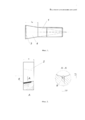
Фиг. 1 - показывает элемент болта - стержень;FIG. 1 - shows a bolt element - a rod;
Фиг. 2 - показывает элемент болта - головку с пазом с установленным в него прутком;FIG. 2 - shows a bolt element - a head with a groove with a bar installed in it;
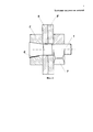
Фиг. 3 - соединение деталей в разрезе.FIG. 3 - connection of parts in section.
Обозначения на фигурахSymbols on the figures
1 - стержень;1 - rod;
2 - головка;2 - head;
3 - шлиц;3 - slot;
4 - конусный участок стержня;4 - conical section of the rod;
5 и 5′ - соединяемые детали;5 and 5 ′ - connected parts;
6 - пруток;6 - bar;
7 - гайка.7 - a nut.
Осуществление изобретенияThe implementation of the invention
Соединение по данному изобретению осуществляют следующим образом.The compound of this invention is as follows.
Болт изготавливают из двух отдельных составляющих элементов:The bolt is made of two separate constituent elements:
- стержня, выполняемого с цилиндрическим участком, несущим резьбу с одного конца, и с конусным расширением на другом конце, противоположном концу с нанесенной стандартной резьбой;- a rod made with a cylindrical section carrying a thread from one end, and with a conical extension at the other end, the opposite end with a standard thread applied;
- головки с конусным сквозным отверстием, угол конуса которого соответствует углу конусности расширяющегося участка стержня и с пазом под установку прутка.- heads with a conical through hole, the cone angle of which corresponds to the taper angle of the expanding section of the rod and with a groove for the installation of the bar.
Головку 2 (см. фиг. 2) выполняют с высотой h=(0,65-1)dc (диаметра стержня).The head 2 (see Fig. 2) is performed with a height h = (0.65-1) d c (rod diameter).
Стержень 1 (см. фиг. 1) выполнен с конусным расширением 4 с углом конуса, равным 6-15°. При угле конуса меньше 6° не обеспечивается достаточно прочного соединения стержня с головкой при габаритных (или геометрических) параметрах головок стандартных болтов. Кроме того, при меньших углах не обеспечивается требуемое качество деталей, поскольку при принятых допусках возможно значительное заглубление конусного участка стержня в конусное отверстие головки. При углах конусности больше 15° резко уменьшается КИМ, а эффект практически не меняется.The rod 1 (see Fig. 1) is made with a
Конусный и цилиндрический участки стержня сопряжены радиусной поверхностью. Длина конусного участка Lк стержня составляет (1,4-1,5)h, где h - высота стандартной головки. При меньшей длине Lк коническая поверхность головки не размещается целиком на конической поверхности стержня и выступающая за торец стержня часть головки не несет полезной нагрузки. При большей длине Lк лишняя часть стержня выступает из головки, не несет полезной нагрузки, также снижается КИМ. Предусмотрен запас длины конического участка стержня - 0,5 мм для возможного при затяжке продвижения стержня относительно головки.The conical and cylindrical sections of the rod are conjugated by a radius surface. The length of the conical portion L k of the rod is (1.4-1.5) h, where h is the height of the standard head. With a shorter length L k, the conical surface of the head does not fit entirely on the conical surface of the rod and the part of the head protruding beyond the end of the rod does not carry a payload. With a greater length L k, the excess part of the rod protrudes from the head, does not carry a payload, and the CMM is also reduced. There is a margin of the length of the conical section of the rod - 0.5 mm for possible when tightening the progress of the rod relative to the head.
С данным болтом используются стандартные гайки с диаметром резьбы, соответствующим диаметру резьбы стержня.With this bolt, standard nuts with a thread diameter corresponding to the diameter of the thread of the rod are used.
Головку и стержень возможно изготавливать из разных материалов в зависимости от условий работы соединения: рабочей среды, температурных условий и др. специальных технических требований. Так, например, возможны комбинации: титан с титаном; титан со сталью; титан с медью или медными сплавами.The head and the rod can be made of different materials depending on the working conditions of the connection: the working environment, temperature conditions and other special technical requirements. So, for example, combinations are possible: titanium with titanium; titanium with steel; titanium with copper or copper alloys.
Соединение деталей болтом выполняется следующим образом.The connection of parts with a bolt is as follows.
В соединяемых деталях 5 и 5′ (см. фиг. 3) сверлят отверстие (лучше - в сборе).In the
Предварительно в канавку (паз) на конической поверхности головки укладывают пруток 6 от большего диаметра головки, замеряют величину выступа прутка над конической поверхностью головки. Если выступ в пределах 0,2-0,3 мм, то стержень 1 вводят цилиндрическим концом в конусное отверстие головки со стороны ее большего диаметра до соприкосновения конических поверхностей стержня 1 и головки 2; вводят стержень 1 цилиндрическим участком с резьбой в отверстие в собранных под крепление деталей 5 и 5′ и продвигают его до контакта опорной поверхности головки с поверхностью детали. На выступающую из детали резьбовую цилиндрическую часть стержня 1 навинчивают стандартную гайку 7 и затягивают ее, при этом с использованием, например, отвертки, которую вставляют в шлиц 3 на расширенном торце стержня, удерживают его от вращения относительно головки и гайку затягивают.Previously, a
Преимущества предлагаемого изобретения крепления пакета из двух и более деталей и элементов крепления для него:The advantages of the invention of fastening a package of two or more parts and fastening elements for it:
- повышение усталостной прочности соединения за счет устранения причин ослабления опасной зоны стержня вблизи опорной поверхности головки, таких как концентрация напряжений;- increasing the fatigue strength of the connection by eliminating the causes of the weakening of the danger zone of the rod near the support surface of the head, such as stress concentration;
- возможность использования для стержня и головки разных конструкционных материалов в зависимости от технических требований в условиях эксплуатации;- the possibility of using different structural materials for the rod and head, depending on the technical requirements in operating conditions;
- раздельное изготовление стержня и головки улучшает условия механической обработки и получение более высокой чистоты поверхности стержня в опасной зоне сопряжения его цилиндрической поверхности с конусной, что особенно важно для повышения прочности и ресурса.- separate manufacture of the rod and the head improves the machining conditions and obtaining a higher purity of the surface of the rod in the danger zone of the interface between its cylindrical surface and the conical, which is especially important to increase strength and resource.
Claims (1)
Priority Applications (1)
| Application Number | Priority Date | Filing Date | Title |
|---|---|---|---|
| RU2015108362/12A RU2605373C2 (en) | 2015-03-11 | 2015-03-11 | Bolted connection of components |
Applications Claiming Priority (1)
| Application Number | Priority Date | Filing Date | Title |
|---|---|---|---|
| RU2015108362/12A RU2605373C2 (en) | 2015-03-11 | 2015-03-11 | Bolted connection of components |
Publications (2)
| Publication Number | Publication Date |
|---|---|
| RU2015108362A RU2015108362A (en) | 2016-09-27 |
| RU2605373C2 true RU2605373C2 (en) | 2016-12-20 |
Family
ID=57018311
Family Applications (1)
| Application Number | Title | Priority Date | Filing Date |
|---|---|---|---|
| RU2015108362/12A RU2605373C2 (en) | 2015-03-11 | 2015-03-11 | Bolted connection of components |
Country Status (1)
| Country | Link |
|---|---|
| RU (1) | RU2605373C2 (en) |
Citations (3)
| Publication number | Priority date | Publication date | Assignee | Title |
|---|---|---|---|---|
| US1747082A (en) * | 1926-10-27 | 1930-02-11 | Ferdinand Maximiliaan Paul De | Nut or screw connection with device to prevent loosening |
| US3058386A (en) * | 1957-09-25 | 1962-10-16 | Earle L Morrow | Binding device with contracting segments having radius smaller than rod engaged thereby |
| SU1703871A1 (en) * | 1989-04-25 | 1992-01-07 | Новгородский Политехнический Институт | Joint of parts with one-sided access |
-
2015
- 2015-03-11 RU RU2015108362/12A patent/RU2605373C2/en not_active IP Right Cessation
Patent Citations (3)
| Publication number | Priority date | Publication date | Assignee | Title |
|---|---|---|---|---|
| US1747082A (en) * | 1926-10-27 | 1930-02-11 | Ferdinand Maximiliaan Paul De | Nut or screw connection with device to prevent loosening |
| US3058386A (en) * | 1957-09-25 | 1962-10-16 | Earle L Morrow | Binding device with contracting segments having radius smaller than rod engaged thereby |
| SU1703871A1 (en) * | 1989-04-25 | 1992-01-07 | Новгородский Политехнический Институт | Joint of parts with one-sided access |
Also Published As
| Publication number | Publication date |
|---|---|
| RU2015108362A (en) | 2016-09-27 |
Similar Documents
| Publication | Publication Date | Title |
|---|---|---|
| US10907677B2 (en) | Asymmetric fastener recess and key | |
| US1969796A (en) | Separable fastener and installation thereof | |
| EP3364049B1 (en) | Radiused lead-in for interference fit fasteners | |
| US20150176623A1 (en) | Self-Drilling and Tapping Screw for Directly Screwing Together Components Without Pilot Holes and A Component Assembly Made in This Way | |
| CN102138010A (en) | Washer, screw or nut with increased coefficient of friction | |
| KR20100021529A (en) | Thread forming screw thread and corresponding thread roll die | |
| JP7106606B2 (en) | wood screw structure | |
| JP2018527532A (en) | Blind fastener | |
| WO2020237910A1 (en) | Anti-loose screw nut assembly | |
| CN204805264U (en) | Connecting elements, pairs of connecting elements, forming tools and taps | |
| JP2021165587A (en) | Looseness prevention nut | |
| US10562158B1 (en) | Self-locking fastener system and process | |
| RU2605373C2 (en) | Bolted connection of components | |
| RU2384762C2 (en) | Procedure for bolt connection of parts | |
| KR20120050806A (en) | An internal screw forming guide tap | |
| US7341414B2 (en) | Fastener and method for reducing stress failure in an engine component | |
| CN118391336B (en) | Structure-based anti-loosening screw pair and connecting method | |
| CN206111782U (en) | Bolt of connecting fastening | |
| JP2009174564A (en) | Bolt and fastener using the same, and bolt manufacturing method | |
| US3599692A (en) | Pierce nut | |
| US20230112581A1 (en) | Multi-piece fastener comprising a tapered threaded portion and method of fastening | |
| JP2009108958A (en) | Screw, connection fixing method, and repair method | |
| JP7667977B2 (en) | Blind Fastener | |
| RU2533705C1 (en) | Method and device for tightening and loosening of high-load threaded joint | |
| CN112576597A (en) | High-strength ball joint bolt |
Legal Events
| Date | Code | Title | Description |
|---|---|---|---|
| MM4A | The patent is invalid due to non-payment of fees |
Effective date: 20170312 |