RU2605270C2 - Injection system cooling and turbine (options) - Google Patents
Injection system cooling and turbine (options) Download PDFInfo
- Publication number
- RU2605270C2 RU2605270C2 RU2012158300/06A RU2012158300A RU2605270C2 RU 2605270 C2 RU2605270 C2 RU 2605270C2 RU 2012158300/06 A RU2012158300/06 A RU 2012158300/06A RU 2012158300 A RU2012158300 A RU 2012158300A RU 2605270 C2 RU2605270 C2 RU 2605270C2
- Authority
- RU
- Russia
- Prior art keywords
- injection cooling
- several
- injection
- turbine
- holes
- Prior art date
Links
Images
Classifications
-
- F—MECHANICAL ENGINEERING; LIGHTING; HEATING; WEAPONS; BLASTING
- F01—MACHINES OR ENGINES IN GENERAL; ENGINE PLANTS IN GENERAL; STEAM ENGINES
- F01D—NON-POSITIVE DISPLACEMENT MACHINES OR ENGINES, e.g. STEAM TURBINES
- F01D5/00—Blades; Blade-carrying members; Heating, heat-insulating, cooling or antivibration means on the blades or the members
- F01D5/12—Blades
- F01D5/14—Form or construction
- F01D5/18—Hollow blades, i.e. blades with cooling or heating channels or cavities; Heating, heat-insulating or cooling means on blades
- F01D5/186—Film cooling
-
- F—MECHANICAL ENGINEERING; LIGHTING; HEATING; WEAPONS; BLASTING
- F01—MACHINES OR ENGINES IN GENERAL; ENGINE PLANTS IN GENERAL; STEAM ENGINES
- F01D—NON-POSITIVE DISPLACEMENT MACHINES OR ENGINES, e.g. STEAM TURBINES
- F01D25/00—Component parts, details, or accessories, not provided for in, or of interest apart from, other groups
- F01D25/08—Cooling; Heating; Heat-insulation
-
- F—MECHANICAL ENGINEERING; LIGHTING; HEATING; WEAPONS; BLASTING
- F01—MACHINES OR ENGINES IN GENERAL; ENGINE PLANTS IN GENERAL; STEAM ENGINES
- F01D—NON-POSITIVE DISPLACEMENT MACHINES OR ENGINES, e.g. STEAM TURBINES
- F01D5/00—Blades; Blade-carrying members; Heating, heat-insulating, cooling or antivibration means on the blades or the members
- F01D5/12—Blades
- F01D5/14—Form or construction
- F01D5/18—Hollow blades, i.e. blades with cooling or heating channels or cavities; Heating, heat-insulating or cooling means on blades
- F01D5/187—Convection cooling
-
- F—MECHANICAL ENGINEERING; LIGHTING; HEATING; WEAPONS; BLASTING
- F01—MACHINES OR ENGINES IN GENERAL; ENGINE PLANTS IN GENERAL; STEAM ENGINES
- F01D—NON-POSITIVE DISPLACEMENT MACHINES OR ENGINES, e.g. STEAM TURBINES
- F01D9/00—Stators
- F01D9/06—Fluid supply conduits to nozzles or the like
- F01D9/065—Fluid supply or removal conduits traversing the working fluid flow, e.g. for lubrication-, cooling-, or sealing fluids
-
- F—MECHANICAL ENGINEERING; LIGHTING; HEATING; WEAPONS; BLASTING
- F05—INDEXING SCHEMES RELATING TO ENGINES OR PUMPS IN VARIOUS SUBCLASSES OF CLASSES F01-F04
- F05D—INDEXING SCHEME FOR ASPECTS RELATING TO NON-POSITIVE-DISPLACEMENT MACHINES OR ENGINES, GAS-TURBINES OR JET-PROPULSION PLANTS
- F05D2240/00—Components
- F05D2240/80—Platforms for stationary or moving blades
- F05D2240/81—Cooled platforms
-
- F—MECHANICAL ENGINEERING; LIGHTING; HEATING; WEAPONS; BLASTING
- F05—INDEXING SCHEMES RELATING TO ENGINES OR PUMPS IN VARIOUS SUBCLASSES OF CLASSES F01-F04
- F05D—INDEXING SCHEME FOR ASPECTS RELATING TO NON-POSITIVE-DISPLACEMENT MACHINES OR ENGINES, GAS-TURBINES OR JET-PROPULSION PLANTS
- F05D2260/00—Function
- F05D2260/20—Heat transfer, e.g. cooling
- F05D2260/201—Heat transfer, e.g. cooling by impingement of a fluid
Abstract
Description
ОБЛАСТЬ ТЕХНИКИFIELD OF TECHNOLOGY
[0101] Настоящая заявка и ожидаемый патент относятся в целом к газотурбинным двигателям и, более конкретно, к системе инжекционного охлаждения для равномерного охлаждения фасонных поверхностей в газовой турбине и в других местах в упрощенной конструкции.[0101] This application and the pending patent relate generally to gas turbine engines and, more specifically, to an injection cooling system for uniformly cooling shaped surfaces in a gas turbine and elsewhere in a simplified design.
ПРЕДПОСЫЛКИ ИЗОБРЕТЕНИЯBACKGROUND OF THE INVENTION
[0102] Системы инжекционного охлаждения используются с турбинными машинами для охлаждения элементов различных типов, таких как корпуса, рабочие лопатки, сопловые лопатки и тому подобное. Системы инжекционного охлаждения охлаждают элементы турбины посредством воздушного потока с обеспечением поддержания достаточного зазора между элементами и адекватного срока службы элементов. Одна из проблем с известными системами инжекционного охлаждения заключается в способности поддерживать равномерный коэффициент теплопередачи через неоднородные или фасонные поверхности. Поддержание постоянного коэффициента теплопередачи обычно требует, чтобы общая форма пластин инжекционного охлаждения повторяла контуры охлаждаемой поверхности. Создание профильных пластин инжекционного охлаждения, однако, может быть дорогостоящим и может привести к неравномерности в них охлаждающего потока.[0102] Injection cooling systems are used with turbine machines to cool various types of elements, such as housings, rotor blades, nozzle blades and the like. Injection cooling systems cool the elements of the turbine by means of an air stream, ensuring that there is sufficient clearance between the elements and an adequate service life of the elements. One of the problems with known injection cooling systems is the ability to maintain a uniform heat transfer coefficient across inhomogeneous or shaped surfaces. Maintaining a constant heat transfer coefficient usually requires that the overall shape of the injection cooling plates follow the contours of the surface to be cooled. The creation of injection cooling profile plates, however, can be expensive and can lead to uneven cooling flow in them.
[0103] Поэтому имеется стремление к созданию усовершенствованной системы инжекционного охлаждения. Такая усовершенствованная система инжекционного охлаждения может обеспечивать постоянные коэффициенты теплопередачи на фасонной поверхности в упрощенной конструкции с низкой стоимостью при сохранении адекватной эффективности охлаждения.[0103] Therefore, there is a desire to create an improved injection cooling system. Such an improved injection cooling system can provide constant heat transfer coefficients on the shaped surface in a simplified low cost design while maintaining adequate cooling efficiency.
СУЩНОСТЬ ИЗОБРЕТЕНИЯSUMMARY OF THE INVENTION
[0104] Настоящая заявка и ожидаемый патент обеспечивают, тем самым, систему инжекционного охлаждения для использования с фасонной поверхностью. Система инжекционного охлаждения может содержать камеру инжекционного охлаждения и пластину инжекционного охлаждения прямолинейной формы, обращенную к фасонной поверхности. Пластина инжекционного охлаждения может содержать ряд спроецированных областей с рядом отверстий инжекционного охлаждения разных размеров и с разными расстояниями между ними.[0104] The present application and the pending patent thus provide an injection cooling system for use with a shaped surface. The injection cooling system may include an injection cooling chamber and a rectilinear injection cooling plate facing the contoured surface. The injection cooling plate may contain a number of projected areas with a number of injection cooling holes of different sizes and with different distances between them.
[0105] Настоящая заявка и ожидаемый патент дополнительно обеспечивают турбину. Турбина может содержать сопловую лопатку, систему инжекционного охлаждения с рядом отверстий инжекционного охлаждения различных размеров и расстояний между ними и элемент с фасонной поверхностью, расположенный вокруг системы инжекционного охлаждения.[0105] The present application and the pending patent further provide a turbine. The turbine may include a nozzle blade, an injection cooling system with a series of injection cooling holes of various sizes and distances between them, and an element with a shaped surface located around the injection cooling system.
[0106] Настоящая заявка и ожидаемый патент дополнительно обеспечивают турбину. Турбина может содержать сопловую лопатку, систему инжекционного охлаждения прямолинейной формы, имеющую ряд отверстий инжекционного охлаждения различных размеров и расстояний между ними, и элемент с фасонной поверхностью, расположенный вокруг системы инжекционного охлаждения так, что указанная система поддерживает фасонные поверхности, по существу, с постоянным коэффициентом теплопередачи между ними.[0106] The present application and the pending patent further provide a turbine. The turbine may comprise a nozzle blade, a rectilinear injection cooling system having a series of injection cooling holes of various sizes and distances between them, and an element with a shaped surface located around the injection cooling system so that said system supports shaped surfaces with a substantially constant coefficient heat transfer between them.
[0107] Эти и другие признаки и усовершенствования настоящей заявки и ожидаемого патента станут очевидными для специалиста при рассмотрении последующего подробного описания в сочетании с чертежами и прилагаемой формулой изобретения.[0107] These and other features and improvements of the present application and the pending patent will become apparent to those skilled in the art upon consideration of the following detailed description in conjunction with the drawings and the appended claims.
КРАТКОЕ ОПИСАНИЕ ЧЕРТЕЖЕЙBRIEF DESCRIPTION OF THE DRAWINGS
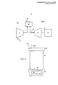
[0108] Фиг.1 представляет собой схему газотурбинного двигателя, изображающую компрессор, камеру сгорания и турбину.[0108] FIG. 1 is a diagram of a gas turbine engine depicting a compressor, a combustion chamber, and a turbine.
[0109] Фиг.2 представляет собой частичный вид сбоку сопловой лопатки с выполненной в ней системой инжекционного охлаждения.[0109] Figure 2 is a partial side view of a nozzle blade with an injection cooling system configured therein.
[0110] Фиг.3 представляет собой частичный вид сбоку сопловой лопатки с системой инжекционного охлаждения, как может быть описано в настоящем документе.[0110] Figure 3 is a partial side view of a nozzle blade with an injection cooling system, as can be described herein.
[0111] Фиг.4 представляет собой вид в аксонометрии сетки инжекционного охлаждения, наложенной на фасонную поверхность, изображенную на Фиг.3.[0111] FIG. 4 is a perspective view of an injection cooling grid superimposed on the contoured surface shown in FIG. 3.
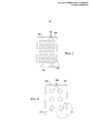
[0112] Фиг.5 представляет собой вид сверху части пластины инжекционного охлаждения, изображенной на Фиг.3.[0112] FIG. 5 is a plan view of a portion of the injection cooling plate shown in FIG. 3.
[0113] Фиг.6 представляет собой вид сверху части пластины инжекционного охлаждения, изображенной на Фиг.3.[0113] FIG. 6 is a plan view of a portion of the injection cooling plate shown in FIG. 3.
ПОДРОБНОЕ ОПИСАНИЕDETAILED DESCRIPTION
[0114] Обратимся теперь к чертежам, на которых одинаковые номера позиций относятся к одинаковым элементам на нескольких видах. Фиг.1 изображает схему газотурбинного двигателя 10, который может быть использован в настоящем документе. Газотурбинный двигатель 10 может содержать компрессор 15. Компрессор 15 сжимает входящий лоток воздуха 20. Компрессор 15 подает сжатый поток воздуха 20 в камеру 25 сгорания. Камера 25 сгорания смешивает сжатый поток воздуха 20 с находящимся под давлением потоком топлива 30 и воспламеняет смесь для создания потока газообразных продуктов 35 сгорания. Несмотря на то, что показана только одна камера 25 сгорания, газотурбинный двигатель 10 может содержать любое количество камер 25 сгорания. Поток газообразных продуктов 35 сгорания, в свою очередь, доставляется в турбину 40. Поток газообразных продуктов 35 сгорания приводит в действие турбину 40, чтобы получить механическую работу. Механическая работа, произведенная в турбине 40, приводит в действие компрессор 15 через вал 45 и внешнюю нагрузку 50, такую как электрический генератор и тому подобное.[0114] Turning now to the drawings, in which like reference numerals refer to like elements in several views. Figure 1 depicts a diagram of a
[0115] Газотурбинный двигатель 10 может использовать природный газ, различные виды синтез-газа и/или другие виды топлива. Газотурбинный двигатель 10 может представлять собой любой двигатель, выбранный из целого ряда различных газотурбинных двигателей, выпускаемых компанией General Electric Company в Скенектэди, штат Нью-Йорк, США, в том числе, но не ограничиваясь этим, например, тяжелые газотурбинные двигатели 7 или 9 серии и тому подобное. Газотурбинный двигатель 10 может иметь различные конфигурации и может использовать другие типы элементов. В настоящем документе также могут быть использованы и другие типы газотурбинных двигателей. В настоящем документе вместе также могут быть использованы несколько газотурбинных двигателей, другие типы турбин и другие виды энергетического оборудования.[0115] The
[0116] На Фиг.2 приведен пример сопловой лопатки 55, которая может быть использована с турбиной 40, описанной выше. Как в целом описано, сопловая лопатка 55 может содержать аэродинамическую часть 60, проходящую между внутренней платформой 65 и наружной платформой 70.[0116] Figure 2 shows an example of a
Некоторое количество сопловых лопаток 55 может быть объединено в расположенный в окружном направлении ряд для формирования ступени вместе с некоторым количеством рабочих лопаток (не показаны). Сопловые лопатки 55 также могут содержать систему инжекционного охлаждения в виде камеры 80 инжекционного охлаждения. Камера 80 может иметь ряд выполненных в ней отверстий 85. Камера 80 может находиться в сообщении с потоком воздуха 20 из компрессора 15 или другим источником с помощью охлаждающего трубопровода 90. Поток воздуха 20 проходит через сопловую лопатку 60 в камеру 80 и наружу через отверстия 85 инжекционного охлаждения таким образом, чтобы инжекционно охлаждать часть сопловой лопатки 55 или другое место. Известны и другие типы камер 80 инжекционного охлаждения.A certain number of
[0117] Известны многие другие типы систем инжекционного охлаждения. Эти известные системы инжекционного охлаждения, однако, как правило, имеют равномерный размер и форму, как описано выше. Кроме того, пластина инжекционного охлаждения может иметь форму, повторяющую контуры охлаждаемой поверхности, чтобы поддерживать постоянный коэффициент теплопередачи по всей поверхности.[0117] Many other types of injection cooling systems are known. These known injection cooling systems, however, are generally uniform in size and shape, as described above. In addition, the injection cooling plate may have a shape that follows the contours of the surface to be cooled in order to maintain a constant heat transfer coefficient over the entire surface.
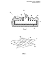
[0118] Фиг.3 и Фиг.4 показывают пример системы 100 инжекционного охлаждения, как может быть описано в настоящем документе. Система 100 может содержать камеру 110 инжекционного охлаждения, которая может содержать полость 120, ограниченную пластиной 130 инжекционного охлаждения и крышкой 140. Камера 110 может находиться в сообщении с охлаждающим потоком 150 через охлаждающий трубопровод 160. Охлаждающий трубопровод 160 может находиться в сообщении с компрессором 15 или другим источником 150 охлаждающего потока.[0118] FIG. 3 and FIG. 4 show an example of an
[0119] Пластина 130 камеры 110 может иметь, по существу, плоскую или прямолинейную поверхность 170. Пластина 130 также может иметь ряд выполненных в ней отверстий 180 инжекционного охлаждения. Размер, форма, конфигурация и расположение отверстий 180 инжекционного охлаждения может варьироваться, как будет описано более подробно ниже. В настоящем документе могут быть использованы другие элементы и другие конфигурации.[0119] The
[0120] Система 100 инжекционного охлаждения может быть использована с любым типом элементов турбины или любых элементов, требующих охлаждения. В этом примере система 100 может быть использована с волнистой или фасонной поверхностью 200. Фасонная поверхность 200 может иметь любую требуемую форму или конфигурацию. В этом примере фасонная поверхность 200 может содержать ряд фасонных областей на разных расстояниях от системы 100 инжекционного охлаждения.[0120]
[0121] Для того чтобы поддерживать постоянный коэффициент теплопередачи через фасонные поверхности 200, расстояния между отверстиями 180 в пластине 130 камеры 110 могут корректироваться дискретным образом для компенсации волнистости на фасонной поверхности 200. Фасонная поверхность 200 может быть разделена на сетку 290 с фасонными областями 300 на ней. Каждая из фасонных областей 300 может быть спроецирована на соответствующие спроецированные области 305 на пластине 130 инжекционного охлаждения. Каждая из областей 305 пластины 130 может иметь отверстия 180 инжекционного охлаждения различных размеров, формы и конфигурации, основываясь на смещении противоположных областей 300 от спроецированной области 305. Группа отверстий 180 инжекционного охлаждения в каждой из спроецированных областей 305 может, таким образом, иметь размер 310 и расстояние 320 между ними, причем и то, и другое может быть равномерно скорректировано по локальной спроецированной области 305 для поддержания среднего коэффициента теплопередачи в дискретной области 300 фасонной поверхности 200. Каждое из отверстий 180 инжекционного охлаждения может, таким образом, иметь переменный размер 310 и переменное расстояние 320 или их набор, в котором как размер 310, так и расстояние 320 поддерживаются постоянными в заданной спроецированной области 305. Например, первая область 330 может иметь близко расположенные небольшие отверстия 180, тогда как вторая область 340 может иметь ряд далеко отстоящих друг от друга больших отверстий 180. В настоящем документе могут быть использованы любое количество размеров и положений в любом количестве спроецированных областей 305 в зависимости от расстояния до противоположной поверхности.[0121] In order to maintain a constant heat transfer coefficient through the shaped
[0122] Система 100 инжекционного охлаждения использует, таким образом, камеру 110 инжекционного охлаждения для обеспечения адекватного охлаждения с упрощенной конструкцией пластины инжекционного охлаждения, так чтобы снизить затраты и увеличить производительность. В частности, отверстия 180 инжекционного охлаждения могут варьироваться в части отношения диаметра отверстия к толщине пластины 130 инжекционного охлаждения, отношения высоты канала к диаметру отверстия и ортогонального расстояния между отверстиями в ряду. Эффективность может рассматриваться в контексте требований к соотношению Z/D, где D является диаметрами отверстия, a Z является средним расстоянием от спроецированной области 305 до фасонной области 300, и/или к соотношению X/D, где Х измеряется по длине пластины 130. В каждой спроецированной области 305 сетки 290 размер отверстий 180 может быть отрегулирован для поддержания нужных требований к соотношению Z/D. В той же самой области 305 положение отверстия или X/D также может быть отрегулировано для поддержания эффективности. Таким образом, пластина 130 камеры 110 может поддерживать согласующиеся коэффициенты теплопередачи с использованием линейной поверхности 170 в отличие от фасонной поверхности.[0122] The
[0123] Следует понимать, что вышеизложенное относится только к определенным вариантам выполнения настоящей заявки и ожидаемого патента. Специалистом в настоящем документе могут быть выполнены многочисленные изменения и модификации без отхода от общего объема и сущности изобретения, как определено в формуле изобретения и в ее эквивалентах.[0123] It should be understood that the foregoing applies only to certain embodiments of the present application and the pending patent. Numerous changes and modifications may be made by one skilled in the art without departing from the general scope and spirit of the invention, as defined in the claims and their equivalents.
Claims (20)
камеру инжекционного охлаждения,
пластину инжекционного охлаждения, обращенную к фасонной поверхности и имеющую прямолинейную форму, причем пластина инжекционного охлаждения имеет несколько спроецированных областей,
при этом указанные несколько спроецированных областей содержат несколько отверстий инжекционного охлаждения разных размеров и с разными расстояниями между ними.1. An injection cooling system for use with a contoured surface, comprising:
injection cooling chamber,
the injection cooling plate facing the shaped surface and having a straight shape, and the injection cooling plate has several projected areas,
however, these several projected areas contain several injection cooling holes of different sizes and with different distances between them.
сопловую лопатку,
систему инжекционного охлаждения, имеющую отверстия инжекционного охлаждения с несколькими размерами и несколькими расстояниями между ними, и
элемент, расположенный около системы инжекционного охлаждения,
причем указанный элемент турбины имеет фасонную поверхность.10. A turbine containing:
nozzle blade
an injection cooling system having injection cooling holes with several sizes and several distances between them, and
an element located near the injection cooling system,
wherein said turbine element has a contoured surface.
сопловую лопатку,
систему инжекционного охлаждения, которая содержит пластину инжекционного охлаждения прямолинейной формы с несколькими отверстиями инжекционного охлаждения нескольких размеров и с несколькими расстояниями между ними, и
элемент, расположенный около системы инжекционного охлаждения,
причем указанный элемент турбины имеет фасонную поверхность, так что система инжекционного охлаждения поддерживает фасонную поверхность, по существу, с постоянным коэффициентом теплопередачи через нее. 20. A turbine containing:
nozzle blade
an injection cooling system that comprises a rectilinear injection cooling plate with several injection cooling holes of several sizes and with several distances between them, and
an element located near the injection cooling system,
moreover, the specified element of the turbine has a shaped surface, so that the injection cooling system supports the shaped surface, essentially with a constant coefficient of heat transfer through it.
Applications Claiming Priority (2)
| Application Number | Priority Date | Filing Date | Title |
|---|---|---|---|
| US13/345,779 | 2012-01-09 | ||
| US13/345,779 US9039350B2 (en) | 2012-01-09 | 2012-01-09 | Impingement cooling system for use with contoured surfaces |
Publications (2)
| Publication Number | Publication Date |
|---|---|
| RU2012158300A RU2012158300A (en) | 2014-07-10 |
| RU2605270C2 true RU2605270C2 (en) | 2016-12-20 |
Family
ID=47665881
Family Applications (1)
| Application Number | Title | Priority Date | Filing Date |
|---|---|---|---|
| RU2012158300/06A RU2605270C2 (en) | 2012-01-09 | 2012-12-27 | Injection system cooling and turbine (options) |
Country Status (5)
| Country | Link |
|---|---|
| US (1) | US9039350B2 (en) |
| EP (1) | EP2617943B1 (en) |
| JP (1) | JP6169845B2 (en) |
| CN (1) | CN103195506B (en) |
| RU (1) | RU2605270C2 (en) |
Families Citing this family (10)
| Publication number | Priority date | Publication date | Assignee | Title |
|---|---|---|---|---|
| US9562439B2 (en) | 2013-12-27 | 2017-02-07 | General Electric Company | Turbine nozzle and method for cooling a turbine nozzle of a gas turbine engine |
| US10641099B1 (en) | 2015-02-09 | 2020-05-05 | United Technologies Corporation | Impingement cooling for a gas turbine engine component |
| FR3050228B1 (en) * | 2016-04-18 | 2019-03-29 | Safran Aircraft Engines | AIR JET COOLING DEVICE OF A TURBINE HOUSING |
| US20170306775A1 (en) * | 2016-04-21 | 2017-10-26 | General Electric Company | Article, component, and method of making a component |
| US10260356B2 (en) * | 2016-06-02 | 2019-04-16 | General Electric Company | Nozzle cooling system for a gas turbine engine |
| US10544683B2 (en) | 2016-08-30 | 2020-01-28 | Rolls-Royce Corporation | Air-film cooled component for a gas turbine engine |
| JP6508499B1 (en) * | 2018-10-18 | 2019-05-08 | 三菱日立パワーシステムズ株式会社 | Gas turbine stator vane, gas turbine provided with the same, and method of manufacturing gas turbine stator vane |
| CN112178693B (en) * | 2020-10-27 | 2022-04-19 | 西北工业大学 | Offset hole row and cylindrical hole row combined cooling structure for corrugated heat shield |
| CN115451428A (en) * | 2021-06-08 | 2022-12-09 | 中国航发商用航空发动机有限责任公司 | Flame tube wall assembly and method for machining impingement cooling wall thereof |
| CN114991991B (en) * | 2022-05-30 | 2024-04-02 | 中国航发四川燃气涡轮研究院 | Stress application vibration-proof heat shield with cold air adjustable function |
Citations (6)
| Publication number | Priority date | Publication date | Assignee | Title |
|---|---|---|---|---|
| US5320483A (en) * | 1992-12-30 | 1994-06-14 | General Electric Company | Steam and air cooling for stator stage of a turbine |
| RU2081334C1 (en) * | 1993-08-12 | 1997-06-10 | Акционерное общество открытого типа "Самарский научно-технический комплекс им.Н.Д.Кузнецова" | High-revving high-temperature stage of high-pressure turbine |
| US6142730A (en) * | 1997-05-01 | 2000-11-07 | Mitsubishi Heavy Industries, Ltd. | Gas turbine cooling stationary blade |
| US6382906B1 (en) * | 2000-06-16 | 2002-05-07 | General Electric Company | Floating spoolie cup impingement baffle |
| US20020182057A1 (en) * | 2001-05-29 | 2002-12-05 | Liotta Gary Charles | Integral nozzle and shroud |
| RU2382892C1 (en) * | 2008-06-24 | 2010-02-27 | Открытое акционерное общество "Авиадвигатель" | Gas turbine engine |
Family Cites Families (55)
| Publication number | Priority date | Publication date | Assignee | Title |
|---|---|---|---|---|
| US3950114A (en) * | 1968-02-23 | 1976-04-13 | General Motors Corporation | Turbine blade |
| US4187054A (en) | 1978-04-20 | 1980-02-05 | General Electric Company | Turbine band cooling system |
| US4719748A (en) * | 1985-05-14 | 1988-01-19 | General Electric Company | Impingement cooled transition duct |
| US4712979A (en) * | 1985-11-13 | 1987-12-15 | The United States Of America As Represented By The Secretary Of The Air Force | Self-retained platform cooling plate for turbine vane |
| US5197852A (en) | 1990-05-31 | 1993-03-30 | General Electric Company | Nozzle band overhang cooling |
| US5528904A (en) * | 1994-02-28 | 1996-06-25 | Jones; Charles R. | Coated hot gas duct liner |
| WO1996015357A1 (en) | 1994-11-10 | 1996-05-23 | Westinghouse Electric Corporation | Gas turbine vane with a cooled inner shroud |
| US6383602B1 (en) | 1996-12-23 | 2002-05-07 | General Electric Company | Method for improving the cooling effectiveness of a gaseous coolant stream which flows through a substrate, and related articles of manufacture |
| DE59709153D1 (en) * | 1997-07-03 | 2003-02-20 | Alstom Switzerland Ltd | Impact arrangement for a convective cooling or heating process |
| EP0905353B1 (en) * | 1997-09-30 | 2003-01-15 | ALSTOM (Switzerland) Ltd | Impingement arrangement for a convective cooling or heating process |
| US6227798B1 (en) | 1999-11-30 | 2001-05-08 | General Electric Company | Turbine nozzle segment band cooling |
| US6418618B1 (en) | 2000-04-11 | 2002-07-16 | General Electric Company | Method of controlling the side wall thickness of a turbine nozzle segment for improved cooling |
| US6419445B1 (en) | 2000-04-11 | 2002-07-16 | General Electric Company | Apparatus for impingement cooling a side wall adjacent an undercut region of a turbine nozzle segment |
| US6386825B1 (en) | 2000-04-11 | 2002-05-14 | General Electric Company | Apparatus and methods for impingement cooling of a side wall of a turbine nozzle segment |
| US6398486B1 (en) * | 2000-06-01 | 2002-06-04 | General Electric Company | Steam exit flow design for aft cavities of an airfoil |
| US6354795B1 (en) * | 2000-07-27 | 2002-03-12 | General Electric Company | Shroud cooling segment and assembly |
| US6402464B1 (en) * | 2000-08-29 | 2002-06-11 | General Electric Company | Enhanced heat transfer surface for cast-in-bump-covered cooling surfaces and methods of enhancing heat transfer |
| US6503051B2 (en) | 2001-06-06 | 2003-01-07 | General Electric Company | Overlapping interference seal and methods for forming the seal |
| US6652220B2 (en) | 2001-11-15 | 2003-11-25 | General Electric Company | Methods and apparatus for cooling gas turbine nozzles |
| WO2003054360A1 (en) * | 2001-12-13 | 2003-07-03 | Alstom Technology Ltd | Hot gas path subassembly of a gas turbine |
| US6779597B2 (en) * | 2002-01-16 | 2004-08-24 | General Electric Company | Multiple impingement cooled structure |
| US6769865B2 (en) | 2002-03-22 | 2004-08-03 | General Electric Company | Band cooled turbine nozzle |
| US6761529B2 (en) | 2002-07-25 | 2004-07-13 | Mitshubishi Heavy Industries, Ltd. | Cooling structure of stationary blade, and gas turbine |
| US6932568B2 (en) | 2003-02-27 | 2005-08-23 | General Electric Company | Turbine nozzle segment cantilevered mount |
| US6984101B2 (en) | 2003-07-14 | 2006-01-10 | Siemens Westinghouse Power Corporation | Turbine vane plate assembly |
| US7147432B2 (en) * | 2003-11-24 | 2006-12-12 | General Electric Company | Turbine shroud asymmetrical cooling elements |
| US7029228B2 (en) | 2003-12-04 | 2006-04-18 | General Electric Company | Method and apparatus for convective cooling of side-walls of turbine nozzle segments |
| US7524163B2 (en) * | 2003-12-12 | 2009-04-28 | Rolls-Royce Plc | Nozzle guide vanes |
| US7270175B2 (en) * | 2004-01-09 | 2007-09-18 | United Technologies Corporation | Extended impingement cooling device and method |
| US7094026B2 (en) | 2004-04-29 | 2006-08-22 | General Electric Company | System for sealing an inner retainer segment and support ring in a gas turbine and methods therefor |
| US7252481B2 (en) | 2004-05-14 | 2007-08-07 | Pratt & Whitney Canada Corp. | Natural frequency tuning of gas turbine engine blades |
| US7219498B2 (en) | 2004-09-10 | 2007-05-22 | Honeywell International, Inc. | Waffled impingement effusion method |
| US7160078B2 (en) | 2004-09-23 | 2007-01-09 | General Electric Company | Mechanical solution for rail retention of turbine nozzles |
| US7140835B2 (en) | 2004-10-01 | 2006-11-28 | General Electric Company | Corner cooled turbine nozzle |
| US7338253B2 (en) | 2005-09-15 | 2008-03-04 | General Electric Company | Resilient seal on trailing edge of turbine inner shroud and method for shroud post impingement cavity sealing |
| US7669422B2 (en) | 2006-07-26 | 2010-03-02 | General Electric Company | Combustor liner and method of fabricating same |
| US7900433B2 (en) | 2006-08-31 | 2011-03-08 | United Technologies Corporation | Fan exhaust nozzle for turbofan engine |
| US20100310367A1 (en) * | 2006-09-28 | 2010-12-09 | United Technologies Corporation | Impingement cooling of a turbine airfoil with large platform to airfoil fillet radius |
| US8801370B2 (en) | 2006-10-12 | 2014-08-12 | General Electric Company | Turbine case impingement cooling for heavy duty gas turbines |
| US7798775B2 (en) | 2006-12-21 | 2010-09-21 | General Electric Company | Cantilevered nozzle with crowned flange to improve outer band low cycle fatigue |
| EP1978213A2 (en) * | 2007-03-27 | 2008-10-08 | General Electric Company | Mounting system for impingement cooling manifold |
| US8152446B2 (en) * | 2007-08-23 | 2012-04-10 | General Electric Company | Apparatus and method for reducing eccentricity and out-of-roundness in turbines |
| US7946801B2 (en) | 2007-12-27 | 2011-05-24 | General Electric Company | Multi-source gas turbine cooling |
| US20090249791A1 (en) * | 2008-04-08 | 2009-10-08 | General Electric Company | Transition piece impingement sleeve and method of assembly |
| US8118548B2 (en) | 2008-09-15 | 2012-02-21 | General Electric Company | Shroud for a turbomachine |
| US8251652B2 (en) * | 2008-09-18 | 2012-08-28 | Siemens Energy, Inc. | Gas turbine vane platform element |
| US8206115B2 (en) * | 2008-09-26 | 2012-06-26 | General Electric Company | Scalloped surface turbine stage with trailing edge ridges |
| CH700319A1 (en) * | 2009-01-30 | 2010-07-30 | Alstom Technology Ltd | Chilled component for a gas turbine. |
| US8142138B2 (en) | 2009-05-01 | 2012-03-27 | General Electric Company | Turbine engine having cooling pin |
| US20100284800A1 (en) | 2009-05-11 | 2010-11-11 | General Electric Company | Turbine nozzle with sidewall cooling plenum |
| US8015817B2 (en) * | 2009-06-10 | 2011-09-13 | Siemens Energy, Inc. | Cooling structure for gas turbine transition duct |
| EP2282012B1 (en) | 2009-07-03 | 2015-11-25 | Alstom Technology Ltd | Method for replacing a cover plate of a guide vane of a gas turbine |
| US8585357B2 (en) | 2009-08-18 | 2013-11-19 | Pratt & Whitney Canada Corp. | Blade outer air seal support |
| US8684664B2 (en) * | 2010-09-30 | 2014-04-01 | General Electric Company | Apparatus and methods for cooling platform regions of turbine rotor blades |
| US8714909B2 (en) * | 2010-12-22 | 2014-05-06 | United Technologies Corporation | Platform with cooling circuit |
-
2012
- 2012-01-09 US US13/345,779 patent/US9039350B2/en active Active
- 2012-12-27 RU RU2012158300/06A patent/RU2605270C2/en not_active IP Right Cessation
- 2012-12-27 JP JP2012283967A patent/JP6169845B2/en active Active
-
2013
- 2013-01-03 EP EP13150158.7A patent/EP2617943B1/en active Active
- 2013-01-09 CN CN201310008079.8A patent/CN103195506B/en active Active
Patent Citations (6)
| Publication number | Priority date | Publication date | Assignee | Title |
|---|---|---|---|---|
| US5320483A (en) * | 1992-12-30 | 1994-06-14 | General Electric Company | Steam and air cooling for stator stage of a turbine |
| RU2081334C1 (en) * | 1993-08-12 | 1997-06-10 | Акционерное общество открытого типа "Самарский научно-технический комплекс им.Н.Д.Кузнецова" | High-revving high-temperature stage of high-pressure turbine |
| US6142730A (en) * | 1997-05-01 | 2000-11-07 | Mitsubishi Heavy Industries, Ltd. | Gas turbine cooling stationary blade |
| US6382906B1 (en) * | 2000-06-16 | 2002-05-07 | General Electric Company | Floating spoolie cup impingement baffle |
| US20020182057A1 (en) * | 2001-05-29 | 2002-12-05 | Liotta Gary Charles | Integral nozzle and shroud |
| RU2382892C1 (en) * | 2008-06-24 | 2010-02-27 | Открытое акционерное общество "Авиадвигатель" | Gas turbine engine |
Non-Patent Citations (2)
| Title |
|---|
| US 5320483 A, 14.06.2002US. * |
| US. * |
Also Published As
| Publication number | Publication date |
|---|---|
| CN103195506A (en) | 2013-07-10 |
| RU2012158300A (en) | 2014-07-10 |
| US20130177396A1 (en) | 2013-07-11 |
| CN103195506B (en) | 2016-03-02 |
| EP2617943B1 (en) | 2019-03-27 |
| JP6169845B2 (en) | 2017-07-26 |
| EP2617943A3 (en) | 2018-01-03 |
| EP2617943A2 (en) | 2013-07-24 |
| JP2013142396A (en) | 2013-07-22 |
| US9039350B2 (en) | 2015-05-26 |
Similar Documents
| Publication | Publication Date | Title |
|---|---|---|
| RU2605270C2 (en) | Injection system cooling and turbine (options) | |
| US8096772B2 (en) | Turbine vane for a gas turbine engine having serpentine cooling channels within the inner endwall | |
| US20150198050A1 (en) | Internal cooling system with corrugated insert forming nearwall cooling channels for airfoil usable in a gas turbine engine | |
| JP2007231944A (en) | Rotor blade for second phase of compressor | |
| US20130177384A1 (en) | Turbine nozzle compartmentalized cooling system | |
| EP3168423B1 (en) | Rotor blade with tip shroud cooling passages and method of making same | |
| US9963989B2 (en) | Gas turbine engine vane-to-transition duct seal | |
| EP3299586B1 (en) | Seal in a gas turbine engine and corresponding creating method | |
| US10001018B2 (en) | Hot gas path component with impingement and pedestal cooling | |
| US9011078B2 (en) | Turbine vane seal carrier with slots for cooling and assembly | |
| US20200003060A1 (en) | Turbine element for high pressure drop and heat transfer | |
| JP6890930B2 (en) | Impingement cooling spline seal | |
| US10738651B2 (en) | Shroud for gas turbine engine | |
| US8376705B1 (en) | Turbine endwall with grooved recess cavity | |
| US20140093353A1 (en) | Solid seal with cooling pathways | |
| US20160076483A1 (en) | Gas Turbine Nozzle | |
| US11939882B2 (en) | Turbine rotor blade and gas turbine | |
| EP3165713A1 (en) | Turbine airfoil | |
| EP3184736A1 (en) | Angled heat transfer pedestal | |
| US11643935B2 (en) | Turbine blade and gas turbine | |
| US10480327B2 (en) | Components having channels for impingement cooling | |
| EP2647800A2 (en) | Transition nozzle combustion system | |
| US20140193272A1 (en) | Gas Turbine Engine Cooling Systems and Methods Incorporating One or More Cover Plate Assemblies Having One or More Apertures Therein |
Legal Events
| Date | Code | Title | Description |
|---|---|---|---|
| MM4A | The patent is invalid due to non-payment of fees |
Effective date: 20201228 |