RU2605103C2 - Locking guide ring for downhole tool and its manufacturing methods - Google Patents
Locking guide ring for downhole tool and its manufacturing methods Download PDFInfo
- Publication number
- RU2605103C2 RU2605103C2 RU2014119518/03A RU2014119518A RU2605103C2 RU 2605103 C2 RU2605103 C2 RU 2605103C2 RU 2014119518/03 A RU2014119518/03 A RU 2014119518/03A RU 2014119518 A RU2014119518 A RU 2014119518A RU 2605103 C2 RU2605103 C2 RU 2605103C2
- Authority
- RU
- Russia
- Prior art keywords
- ring
- inches
- cutting
- arc
- large arc
- Prior art date
Links
- 238000004519 manufacturing process Methods 0.000 title claims description 10
- 238000000034 method Methods 0.000 claims abstract description 47
- 238000005520 cutting process Methods 0.000 claims abstract description 26
- 230000008569 process Effects 0.000 claims description 9
- 238000003754 machining Methods 0.000 claims description 6
- 238000003698 laser cutting Methods 0.000 claims description 5
- 238000000992 sputter etching Methods 0.000 claims description 5
- 230000015572 biosynthetic process Effects 0.000 claims description 2
- 238000005553 drilling Methods 0.000 abstract description 21
- 239000011435 rock Substances 0.000 abstract description 5
- 238000009527 percussion Methods 0.000 abstract description 2
- 230000014759 maintenance of location Effects 0.000 abstract 1
- 239000002689 soil Substances 0.000 abstract 1
- 239000000126 substance Substances 0.000 abstract 1
- 239000000463 material Substances 0.000 description 15
- 230000007257 malfunction Effects 0.000 description 5
- 230000035939 shock Effects 0.000 description 5
- 230000006378 damage Effects 0.000 description 4
- 230000013011 mating Effects 0.000 description 4
- 230000004048 modification Effects 0.000 description 4
- 238000012986 modification Methods 0.000 description 4
- 238000013461 design Methods 0.000 description 3
- 239000006096 absorbing agent Substances 0.000 description 2
- 238000009760 electrical discharge machining Methods 0.000 description 2
- 238000005516 engineering process Methods 0.000 description 2
- 230000007246 mechanism Effects 0.000 description 2
- 239000002184 metal Substances 0.000 description 2
- 238000007514 turning Methods 0.000 description 2
- 229910001369 Brass Inorganic materials 0.000 description 1
- 229910001209 Low-carbon steel Inorganic materials 0.000 description 1
- 230000009471 action Effects 0.000 description 1
- 229910045601 alloy Inorganic materials 0.000 description 1
- 239000000956 alloy Substances 0.000 description 1
- 230000005540 biological transmission Effects 0.000 description 1
- 239000010951 brass Substances 0.000 description 1
- 210000000078 claw Anatomy 0.000 description 1
- 238000004891 communication Methods 0.000 description 1
- 238000010276 construction Methods 0.000 description 1
- 230000008878 coupling Effects 0.000 description 1
- 238000010168 coupling process Methods 0.000 description 1
- 238000005859 coupling reaction Methods 0.000 description 1
- 238000005336 cracking Methods 0.000 description 1
- 230000007423 decrease Effects 0.000 description 1
- 230000001066 destructive effect Effects 0.000 description 1
- 238000011161 development Methods 0.000 description 1
- 238000006073 displacement reaction Methods 0.000 description 1
- 238000005755 formation reaction Methods 0.000 description 1
- 239000003292 glue Substances 0.000 description 1
- 238000003780 insertion Methods 0.000 description 1
- 230000037431 insertion Effects 0.000 description 1
- 229910001092 metal group alloy Inorganic materials 0.000 description 1
- 230000007704 transition Effects 0.000 description 1
- 238000009423 ventilation Methods 0.000 description 1
- 239000002699 waste material Substances 0.000 description 1
Images


Classifications
-
- E—FIXED CONSTRUCTIONS
- E21—EARTH OR ROCK DRILLING; MINING
- E21B—EARTH OR ROCK DRILLING; OBTAINING OIL, GAS, WATER, SOLUBLE OR MELTABLE MATERIALS OR A SLURRY OF MINERALS FROM WELLS
- E21B4/00—Drives for drilling, used in the borehole
- E21B4/06—Down-hole impacting means, e.g. hammers
- E21B4/14—Fluid operated hammers
-
- E—FIXED CONSTRUCTIONS
- E21—EARTH OR ROCK DRILLING; MINING
- E21B—EARTH OR ROCK DRILLING; OBTAINING OIL, GAS, WATER, SOLUBLE OR MELTABLE MATERIALS OR A SLURRY OF MINERALS FROM WELLS
- E21B17/00—Drilling rods or pipes; Flexible drill strings; Kellies; Drill collars; Sucker rods; Cables; Casings; Tubings
- E21B17/02—Couplings; joints
- E21B17/03—Couplings; joints between drilling rod or pipe and drill motor or surface drive, e.g. between drilling rod and hammer
-
- B—PERFORMING OPERATIONS; TRANSPORTING
- B23—MACHINE TOOLS; METAL-WORKING NOT OTHERWISE PROVIDED FOR
- B23P—METAL-WORKING NOT OTHERWISE PROVIDED FOR; COMBINED OPERATIONS; UNIVERSAL MACHINE TOOLS
- B23P15/00—Making specific metal objects by operations not covered by a single other subclass or a group in this subclass
- B23P15/001—Making specific metal objects by operations not covered by a single other subclass or a group in this subclass valves or valve housings
-
- B—PERFORMING OPERATIONS; TRANSPORTING
- B23—MACHINE TOOLS; METAL-WORKING NOT OTHERWISE PROVIDED FOR
- B23P—METAL-WORKING NOT OTHERWISE PROVIDED FOR; COMBINED OPERATIONS; UNIVERSAL MACHINE TOOLS
- B23P15/00—Making specific metal objects by operations not covered by a single other subclass or a group in this subclass
- B23P15/003—Making specific metal objects by operations not covered by a single other subclass or a group in this subclass bearings
-
- E—FIXED CONSTRUCTIONS
- E21—EARTH OR ROCK DRILLING; MINING
- E21B—EARTH OR ROCK DRILLING; OBTAINING OIL, GAS, WATER, SOLUBLE OR MELTABLE MATERIALS OR A SLURRY OF MINERALS FROM WELLS
- E21B17/00—Drilling rods or pipes; Flexible drill strings; Kellies; Drill collars; Sucker rods; Cables; Casings; Tubings
- E21B17/02—Couplings; joints
- E21B17/04—Couplings; joints between rod or the like and bit or between rod and rod or the like
- E21B17/042—Threaded
- E21B17/0426—Threaded with a threaded cylindrical portion, e.g. for percussion rods
-
- Y—GENERAL TAGGING OF NEW TECHNOLOGICAL DEVELOPMENTS; GENERAL TAGGING OF CROSS-SECTIONAL TECHNOLOGIES SPANNING OVER SEVERAL SECTIONS OF THE IPC; TECHNICAL SUBJECTS COVERED BY FORMER USPC CROSS-REFERENCE ART COLLECTIONS [XRACs] AND DIGESTS
- Y10—TECHNICAL SUBJECTS COVERED BY FORMER USPC
- Y10T—TECHNICAL SUBJECTS COVERED BY FORMER US CLASSIFICATION
- Y10T29/00—Metal working
- Y10T29/49—Method of mechanical manufacture
- Y10T29/49826—Assembling or joining
-
- Y—GENERAL TAGGING OF NEW TECHNOLOGICAL DEVELOPMENTS; GENERAL TAGGING OF CROSS-SECTIONAL TECHNOLOGIES SPANNING OVER SEVERAL SECTIONS OF THE IPC; TECHNICAL SUBJECTS COVERED BY FORMER USPC CROSS-REFERENCE ART COLLECTIONS [XRACs] AND DIGESTS
- Y10—TECHNICAL SUBJECTS COVERED BY FORMER USPC
- Y10T—TECHNICAL SUBJECTS COVERED BY FORMER US CLASSIFICATION
- Y10T29/00—Metal working
- Y10T29/49—Method of mechanical manufacture
- Y10T29/49995—Shaping one-piece blank by removing material
- Y10T29/49996—Successive distinct removal operations
-
- Y—GENERAL TAGGING OF NEW TECHNOLOGICAL DEVELOPMENTS; GENERAL TAGGING OF CROSS-SECTIONAL TECHNOLOGIES SPANNING OVER SEVERAL SECTIONS OF THE IPC; TECHNICAL SUBJECTS COVERED BY FORMER USPC CROSS-REFERENCE ART COLLECTIONS [XRACs] AND DIGESTS
- Y10—TECHNICAL SUBJECTS COVERED BY FORMER USPC
- Y10T—TECHNICAL SUBJECTS COVERED BY FORMER US CLASSIFICATION
- Y10T29/00—Metal working
- Y10T29/49—Method of mechanical manufacture
- Y10T29/49998—Work holding
Landscapes
- Engineering & Computer Science (AREA)
- Life Sciences & Earth Sciences (AREA)
- Geology (AREA)
- Mining & Mineral Resources (AREA)
- Mechanical Engineering (AREA)
- Physics & Mathematics (AREA)
- Environmental & Geological Engineering (AREA)
- Fluid Mechanics (AREA)
- General Life Sciences & Earth Sciences (AREA)
- Geochemistry & Mineralogy (AREA)
- Earth Drilling (AREA)
- Drilling Tools (AREA)
Abstract
Description
Область техники, к которой относится изобретениеFIELD OF THE INVENTION
Настоящее изобретение относится, в общем, к комбинированным скважинным инструментам, содержащим верхний компонент корпуса и нижний присоединенный компонент, имеющий возможность вращения, отклонения или осевого перемещения. Инструменты включают в себя погружные двигатели, погружные турбины, гибкие соединения, амортизационные устройства, ясы, противостопорные инструменты, инструменты для регулирования крутящего момента и зажимные инструменты. В частности, изобретение относится к скважинным ударным молоткам и инструменту для ударного бурения, в частности к устройству для удерживания бурильного долота и/или других компонентов внутри корпуса бурильного молотка во время возникновения неисправности и направления бурильного долота во время бурения и к одному или нескольким способам изготовления устройства.The present invention relates, in general, to combined downhole tools comprising an upper housing component and a lower connected component having the possibility of rotation, deviation or axial movement. Tools include submersible motors, submersible turbines, flexible couplings, shock absorbers, jars, anti-stop tools, torque control tools, and clamping tools. In particular, the invention relates to downhole impact hammers and percussion drilling tools, in particular to a device for holding a drill bit and / or other components inside the drill hammer body during a malfunction and direction of the drill bit during drilling, and to one or more manufacturing methods devices.
Уровень техникиState of the art
Обычный режим работы при отказе во время эксплуатации скважинных ударных молотков и других многокомпонентных скважинных инструментов влечет за собой усталостное разрушение нижнего корпуса или, в случае инструмента, связанного с буровым долотом, разрушение долота или соединительного хвостовика долота. Этот режим работы при отказе может привести к утере некоторой части или всех нижних компонентов инструмента или, в случае инструмента, соединенного с буровым долотом, к утере долота, долота и хвостовика или, как альтернативный вариант, долота, хвостовика и нижнего корпуса инструмента, остающихся в скважине после возникновения неисправности, что создает необходимость выполнения ловильных работ для извлечения этих частей из скважины. В прошлом использовалось множество способов, включая многочисленные конфигурации разъемных стопорных колец, для предотвращения полной потери компонентов, установленных ниже места возникновения неисправности, так чтобы весь узел, даже если он находится в разрушенном состоянии, можно было извлечь из скважины. Пример скважинного инструмента для ударного бурения, который является предметом, по меньшей мере, одного варианта выполнения настоящего изобретения, описывается со ссылкой на чертежи в патенте США №7,377,338, именуемом «Скважинный инструмент для ударного бурения» и выданном на имя Bassinger 27 мая 2008 г, который полностью включен сюда в качестве ссылки.Normal operation during failure during the operation of downhole impact hammers and other multicomponent downhole tools entails fatigue failure of the lower case or, in the case of a tool associated with a drill bit, the destruction of the bit or connecting shank of the bit. This failure mode may result in the loss of some or all of the lower components of the tool or, in the case of a tool connected to the drill bit, to the loss of the bit, bit and shank or, alternatively, the bit, shank and lower tool body remaining in well after a malfunction occurs, which creates the need for fishing operations to extract these parts from the well. In the past, many methods have been used, including multiple split ring retainer configurations, to prevent the complete loss of components installed below the point of failure, so that the entire assembly, even if it is in a destroyed state, can be removed from the well. An example of a downhole tool for impact drilling, which is the subject of at least one embodiment of the present invention, is described with reference to the drawings in US Pat. No. 7,377,338, referred to as “Downhole Tool for Impact Drilling” and issued to Bassinger on May 27, 2008, which is fully incorporated here by reference.
Пример существующего стопорного кольца описывается со ссылкой на чертежи в патенте США №5,390,749, именуемом «Устройство для позиционирования разъемного стопорного кольца в скважинном инструменте для ударного бурения» и выданном на имя Lyon 21 февраля 1995 г. («Lyon»), который полностью включен сюда в качестве ссылки. Альтернативный пример существующего разъемного стопорного кольца описывается со ссылкой на чертежи в заменяющем патенте США № RE 36,002, именуемом «Передающая втулка для погружного пневмоударника» и выданном на имя Elsby и др. 22 декабря 1998 г. («Elsby»), который также полностью включен сюда в качестве ссылки. Другой пример существующего стопорного кольца описывается со ссылкой на чертежи в патенте США №4,924,948, именуемом «Ударопоглощающее стопорное кольцо долота»» и выданном на имя Chuang и др. 15 мая 1990 г. («Chuang»), который также полностью включен сюда в качестве ссылки.An example of an existing retaining ring is described with reference to the drawings in US Pat. No. 5,390,749, referred to as a “Device for Positioning a Detachable Locking Ring in a Downhole Impact Drilling Tool” and issued to Lyon on February 21, 1995 (“Lyon”), which is fully incorporated herein. as a reference. An alternative example of an existing detachable retaining ring is described with reference to the drawings in US Replacement Patent No. RE 36,002, referred to as “Transmission Sleeve for Submersible Hammer Hammer” and issued to Elsby et al. On December 22, 1998 (“Elsby”), which is also fully incorporated. here as a reference. Another example of an existing retaining ring is described with reference to the drawings in US Pat. No. 4,924,948, referred to as the “Shock Absorbing Snap Locking Ring” and issued to Chuang et al. On May 15, 1990 (“Chuang”), which is also fully incorporated herein by reference. links.
Согласно «Lyon» приводится описание проблем, касающихся существующих разъемных колец. «Lyon» указывает, что «В скважинных бурильных молотках обычно используется комплект разъемных стопорных половин колец для удерживания бурового долота в корпусе бурильного молотка. Эти кольца обычно являются плоскими и разъемными, так чтобы они могли укладываться в осевом направлении и удерживаться между внутренними частями бурильного молотка, т.е. патроном и опорой долота. Из-за высоких уровней вибраций и ударных нагрузок на конце долота скважинного бурильного молотка обычные разъемные стопорные кольца предрасположены к радиальному перемещению вперед и назад в пространстве, которое образует разрез между половинами колец. Такое перемещение колец может создать ряд проблем, а именно: 1. трение колец о долото, вызывающее растрескивание долота; 2. неполный контакт между половинами колец и контактным заплечиком долота; 3. повреждение контактной зоны на долоте; и 4. высокие напряжения в половинах кольца». См. Lyon, колонка 1, абзац II, строки 12-28.According to Lyon, problems are described with regard to existing split rings. “Lyon” indicates that “Downhole hammers typically use a set of split retaining halves of rings to hold the drill bit in the body of the drill hammer. These rings are usually flat and split so that they can be stacked axially and held between the inside of the drill hammer, i.e. chuck and chisel support. Due to the high levels of vibration and shock loads at the end of the drill bit, conventional split snap rings are prone to radial movement back and forth in the space that forms the cut between the half rings. Such movement of the rings can create a number of problems, namely: 1. friction of the rings on the bit, causing cracking of the bit; 2. incomplete contact between the halves of the rings and the contact shoulder of the bit; 3. damage to the contact area on the bit; and 4. high stresses in the halves of the ring. " See Lyon, column 1, paragraph II, lines 12-28.
Из описания «Lyon» понятно, что существующие кольца относительно свободно крепятся в имеющемся пространстве. «Lyon» описывает изготовление колец по этому изобретению и указывает, что «Отдельные половины колец изготавливаются из одного полого цилиндрического элемента, который сначала сводится на конус у верхнего и нижнего участков и затем режется по диаметру на две части. Зазор, полученный во время резки, соответствует расстоянию по дуге между половинами колец, собранными в бурильном молотке». См. Lyon, колонка 4, абзац II, строки 11-16 (добавлено подчеркивание). Решение «Lyon» применительно к вышеуказанным проблемам состоит в том, чтобы свести на конус верхний и нижний участки разъемного кольца, так чтобы конусы сопрягались в верхней части нижнего корпуса и в нижней части опоры долота для перемещения разъемных колец наружу к внутреннему диаметру наружного корпуса инструмента. Таким образом, несмотря на существование зазора между двумя половинами колец, «Lyon» предлагает меры по уменьшению радиального перемещения колец назад и вперед, используя конусы на верхней и нижней поверхностях и сопряжение конусов на смежных компонентах. Однако «Lyon» не решает проблему с перемещением, которое вызвано «зазором, полученным в результате резки». Кроме того, наличие зазора уменьшает или устраняет способность разъемного кольца применительно к стабилизации направления перемещения хвостовика долота.From the description of "Lyon" it is clear that existing rings are relatively freely mounted in the available space. “Lyon” describes the manufacture of the rings of this invention and indicates that “The individual halves of the rings are made of one hollow cylindrical element, which is first tapered at the upper and lower sections and then cut in diameter into two parts. The clearance obtained during cutting corresponds to the distance along the arc between the halves of the rings assembled in the drill hammer. " See Lyon, column 4, paragraph II, lines 11-16 (underline added). The Lyon solution for the above problems is to cone the upper and lower sections of the split ring so that the cones mate in the upper part of the lower body and in the lower part of the bit support to move the split rings outward to the inner diameter of the outer tool body. Thus, despite the existence of a gap between the two halves of the rings, Lyon proposes measures to reduce the radial movement of the rings back and forth, using cones on the upper and lower surfaces and mating the cones on adjacent components. However, Lyon does not solve the movement problem caused by the “cutting clearance”. In addition, the presence of a gap reduces or eliminates the ability of the split ring to stabilize the direction of movement of the shank of the bit.
Кроме того, по существующему уровню техники способ резки разъемного кольца из отдельного обточенного кольца (даже используя медленную подачу сильно натянутого и острого полотна пилы) приводит к получению стандартного минимального «зазора» шириной 0,032′′, что создает проблемы, связанные с сосредоточенной нагрузкой, износом, люфтом, механическими напряжениями, наклоном и повреждениями, как описано или упомянуто в «Lyon». Другой причиной наличия ширины зазора по существующему уровню техники было стремление ослабить допуск на крепление комплекта стопорных колец к внутреннему диаметру основания и наружному диаметру хвостовика, поскольку «люфт», обеспечиваемый шириной зазора, мог бы вызвать заклинивание и задирание этих поверхностей. Кроме того, значительная ширина зазора и нежесткие допуски, свойственные существующим стопорным кольцам, приводят к получению меньшего сопротивления боковому перемещению скользящего хвостовика и, таким образом, к непродуктивной и, в конечном счете, разрушающей вибрации.In addition, according to the state of the art, a method of cutting a split ring from a separate turned ring (even using a slow feed of a highly stretched and sharp saw blade) results in a standard minimum “gap” of 0.032 ″ wide, which creates problems associated with concentrated load, wear , backlash, mechanical stress, tilt and damage as described or mentioned in Lyon. Another reason for the presence of a gap width according to the prior art was the desire to weaken the tolerance on fixing a set of retaining rings to the inner diameter of the base and the outer diameter of the shank, since the “backlash” provided by the width of the gap could jam and tear these surfaces. In addition, the significant gap width and non-rigid tolerances inherent in existing retaining rings result in less resistance to lateral movement of the sliding shank and, thus, to unproductive and, ultimately, destructive vibration.
Таким образом, необходимо предложить стопорное кольцо для скважинных инструментов, которое с помощью разъема в целях сборки инструмента действует в сборе как жесткое (или практически жесткое, монолитное или комплектное) кольцо, при этом герметично перемещаясь со скольжением в контакте с внутренним диаметром корпуса и наружным диаметром хвостовика.Thus, it is necessary to propose a retaining ring for downhole tools, which, using a connector for assembly of a tool, acts as a rigid (or practically rigid, monolithic or complete) ring assembly, while moving hermetically with sliding in contact with the inner diameter of the housing and the outer diameter shank.
Краткое описание чертежейBrief Description of the Drawings
Вышеизложенные и другие отличительные характеристики и аспекты изобретения станут понятными после изучения приведенного ниже описания определенных вариантов выполнения со ссылкой на приложенные чертежи, на которых:The above and other distinctive characteristics and aspects of the invention will become apparent after studying the following description of certain embodiments with reference to the attached drawings, in which:
Фиг. 1А - вид сверху на разъемное стопорное направляющее кольцо по варианту выполнения изобретения;FIG. 1A is a plan view of a detachable retaining guide ring according to an embodiment of the invention;
Фиг. 1В - вид в разрезе на разъемное стопорное направляющее кольцо из Фиг. 1А по варианту выполнения изобретения;FIG. 1B is a cross-sectional view of a detachable snap ring of FIG. 1A according to an embodiment of the invention;
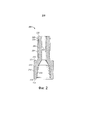
Фиг. 2 - вид в разрезе на оправку, к которой присоединяется разъемное стопорное направляющее кольцо из Фиг. 1А по варианту выполнения изобретения;FIG. 2 is a sectional view of a mandrel to which a detachable retaining guide ring of FIG. 1A according to an embodiment of the invention;
Фиг. 3 - вид в разрезе нижнего конца узла бурильного молотка в сборе во время выполнения нормальных операций бурения с использованием установленного в нем разъемного стопорного направляющего кольца из Фиг. 1А по варианту выполнения изобретения;FIG. 3 is a cross-sectional view of the lower end of the drill hammer assembly during normal drilling operations using the detachable retaining guide ring of FIG. 1A according to an embodiment of the invention;
Фиг. 4 - вид в разрезе нижнего конца узла бурильного молотка в сборе, когда буровое долото переместилось в «выдвинутое» положение, и заплечик оправки контактирует с разъемным стопорным направляющим кольцом из Фиг. 1А по варианту выполнения изобретения;FIG. 4 is a sectional view of the lower end of the drill hammer assembly when the drill bit has moved to the “extended” position and the mandrel shoulder is in contact with the detachable retaining guide ring of FIG. 1A according to an embodiment of the invention;
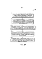
Фиг. 5А - способ образования разъемного стопорного направляющего кольца из Фиг. 1А по варианту выполнения изобретения;FIG. 5A is a method of forming the detachable retaining guide ring of FIG. 1A according to an embodiment of the invention;
Фиг. 5В - вид сверху на первое кольцо, которое используется для образования разъемного стопорного направляющего кольца из Фиг. 1А по способу из Фиг. 5А; иFIG. 5B is a plan view of a first ring that is used to form the split retaining guide ring of FIG. 1A by the method of FIG. 5A; and
Фиг. 6 - способ образования разъемного стопорного направляющего кольца из Фиг. 1А по другому варианту выполнения изобретения.FIG. 6 is a method of forming a detachable locking guide ring from FIG. 1A in another embodiment of the invention.
На чертежах показаны только варианты выполнения изобретения и, следовательно, чертежи не должны рассматриваться как ограничивающие объем изобретения, поскольку оно может распространяться и на другие в равной степени эффективные варианты выполнения.Only embodiments of the invention are shown in the drawings, and therefore, the drawings should not be construed as limiting the scope of the invention, since it may extend to other equally effective embodiments.
Краткое описание вариантов осуществленияBrief Description of Embodiments
Настоящее изобретение относится к устройству для удерживания бурильного долота и/или других компонентов внутри корпуса бурильного молотка во время возникновения неисправности и направления нижнего компонента или бурильного долота во время бурения и к одному или нескольким способам изготовления устройства. Несмотря на то что описание вариантов выполнения приводится ниже со ссылкой на скважинный инструмент для ударного бурения, альтернативные варианты выполнения изобретения могут применяться в скважинных инструмента другого типа, включая сюда, без ограничения, скважинные ударные молотки, амортизирующие, переводники, погружные двигатели, погружные турбины, скважинные инструменты для вращения и средства контроля или любой скважинный бурильный инструмент, которые могут эффективно эксплуатироваться с применением стопорного кольца для получения удерживающего механизма в случае разрушения или возникновения неисправности нижних компонентов или корпуса инструмента.The present invention relates to a device for holding a drill bit and / or other components inside a drill hammer body during a malfunction and direction of the lower component or drill bit during drilling, and to one or more methods for manufacturing the device. Although embodiments are described below with reference to a downhole tool for impact drilling, alternative embodiments of the invention can be applied to downhole tools of a different type, including but not limited to downhole impact hammers, shock absorbers, sub, submersible motors, submersible turbines, downhole rotation tools and controls or any downhole drilling tool that can be efficiently operated using a floor retaining ring exercises of the holding mechanism in case of destruction or malfunction of the lower components or tool body.
Изобретение станет более понятным после изучения приведенного ниже описания неограничивающих вариантов выполнения со ссылкой на приложенные чертежи, при этом похожие части на каждой из фигур обозначены одинаковыми ссылочными номерами. На Фиг. 1А и 1В показаны различные виды разъемного стопорного направляющего кольца 100 по варианту выполнения изобретения. Как показано на Фиг 1А и 1В, разъемное стопорное направляющее кольцо 100 является круглым кольцом, образованным между вокруг центральной оси 105, и включает в себя первую половину 110 кольца и вторую половину 160 кольца. Первая половина 110 кольца и вторая половина 160 кольца являются, по существу, похожими, и поэтому описание только первой половины 110 кольца является достаточным для описания как первой, так и второй половин 110, 160 кольца. Разъемное стопорное направляющее кольцо 100 изготавливается из малоуглеродистой стали; однако могут использоваться другие материалы, включая, без ограничения, высокопрочные сплавы и другие материалы, достаточно твердые, чтобы удерживать компоненты инструмента, поднимаемого на поверхность, и достаточно прочные, чтобы материал не разрушался под действием динамического удара, выполняемого поршнем.The invention will become more clear after studying the following description of non-limiting embodiments with reference to the attached drawings, with similar parts on each of the figures indicated by the same reference numbers. In FIG. 1A and 1B show various views of a detachable
Первая половина 110 кольца имеет полукруглую форму и продолжается от первого конца 112 ко второму концу 116. Первая половина 110 кольца включает в себя верхнюю поверхность 120, нижнюю поверхность 124, внутреннюю поверхность 128 и наружную поверхность 132. По некоторым вариантам выполнения первый конец 112 расположен, по существу, в той же плоскости, что и второй конец 116; однако в других вариантах выполнения первый конец 112 расположен в другой плоскости по сравнению со вторым концом 116. Например, первый конец 112 расположен в другой плоскости по сравнению со вторым концом 116, первая половина 110 кольца имеет меньшую или большую длину дуги по сравнению со второй половиной 160 кольца, однако совместно они образуют кольцеобразное разъемное стопорное направляющее кольцо 100, когда первая половина 110 кольца устанавливается рядом со второй половиной 160 кольца.The
Верхняя поверхность 120, по существу, является плоской в определенных вариантах выполнения; однако верхняя поверхность является неплоской в других вариантах выполнения. Верхняя поверхность 120 ориентирована в плоскости, которая, по существу, является перпендикулярной центральной оси 105. Аналогично, нижняя поверхность 124 является плоской в определенных вариантах выполнения, в то время как в других вариантах выполнения нижняя поверхность 124 является неплоской. Нижняя поверхность 124 также ориентирована в плоскости, которая, по существу, перпендикулярна центральной оси 105 и расположена ниже верхней поверхности 120. По некоторым вариантам выполнения верхняя поверхность 120 и нижняя поверхность 124, по существу, параллельны друг другу; однако верхняя поверхность 120 и нижняя поверхность 124 не параллельны друг другу в других вариантах выполнения. По варианту выполнения расстояние между верхней поверхностью 120 и нижней поверхностью 124 составляет примерно от 0,730 дюйма примерно до 0,735 дюйма; однако этот размер может отличаться от указанного в других вариантах выполнения. В некоторых вариантах выполнения одна или несколько из поверхностей, к которым относятся верхняя поверхность 120 и нижняя поверхность 124, включают в себя одно или несколько образованных в них отверстий 121. По некоторым вариантам выполнения отверстия 121 продолжаются от одной из поверхностей, к которым относятся верхняя поверхность 120 и нижняя поверхность 124, к другой из поверхностей, к которым относятся верхняя поверхность 120 и нижняя поверхность 124. В другом варианте выполнения отверстия 121 продолжаются от одной из поверхностей, к которым относятся верхняя поверхность 120 и нижняя поверхность 124, к другой из поверхностей, к которым относятся верхняя поверхность 120 и нижняя поверхность 124, но не продолжаются до этой другой поверхности. На верхней поверхности 120 предусмотрены четыре отверстия 121, расположенные радиально и на равном расстоянии друг от друга; однако в других вариантах выполнения может быть предусмотрено большее или меньшее количество отверстий, расположенных радиально на равном расстоянии друг от друга или радиально и не на равном расстоянии друг от друга.
Внутренняя поверхность 128 является радиальной поверхностью, которая продолжается, по существу, от первого конца 112 до второго конца 116. Внутренняя поверхность 128 также продолжается, по существу, от нижней поверхности 124, по существу, до верхней поверхности 120. В определенных вариантах выполнения внутренняя поверхность 128 соединена с верхней внутренней скошенной поверхностью 129, которая соединена с внутренним краем верхней поверхности 120. Аналогично, в определенных вариантах выполнения внутренняя поверхность 128 соединена с нижней внутренней скошенной поверхностью 130, которая соединена с внутренним краем верхней поверхности 124. По некоторым вариантам выполнения верхняя внутренняя скошенная поверхность 129 и нижняя внутренняя скошенная поверхность 130 образованы под углом примерно сорок пять градусов относительно верхней поверхности 120 и нижней поверхности 124, соответственно; однако этот угол может быть больше или меньше в других вариантах выполнения. Как вариант, в других вариантах выполнения внутренняя поверхность 128 соединяется непосредственно с одной или несколькими из поверхностей, к которым относятся верхняя поверхность 120 и/или нижняя поверхность 124, или соединяется косвенно с одной или несколькими из поверхностей, к которым относятся верхняя поверхность 120 и/или нижняя поверхность 124, с помощью поверхности других типов вместо или в добавление к скошенным поверхностям. Внутренняя поверхность 128 имеет дугообразную форму, которая образована первым радиусом 131, измеренным от центральной оси 105. По варианту выполнения первый радиус 131 составляет примерно от 2,533 дюйма примерно до 2,535 дюйма; однако этот размер может отличаться от указанного в других вариантах выполнения. По некоторым вариантам выполнения внутренняя поверхность 128 является обработанной поверхностью.The
Наружная поверхность 132 является радиальной поверхностью, которая продолжается, по существу, от первого конца 112 до второго конца 116. Наружная поверхность 132 также продолжается, по существу, от нижней поверхности 124, по существу, до верхней поверхности 120. В определенных вариантах выполнения наружная поверхность 132 соединена с верхней наружной скошенной поверхностью 133, которая соединена с наружным краем верхней поверхности 120. Аналогично, в определенных вариантах выполнения наружная поверхность 132 соединена с нижней наружной скошенной поверхностью 134, которая соединена с наружным краем нижней поверхности 124. По некоторым вариантам выполнения верхняя наружная скошенная поверхность 133 и нижняя наружная скошенная поверхность 134 образованы под углом примерно сорок пять градусов относительно верхней поверхности 120 и нижней поверхности 124, соответственно; однако этот угол может быть больше или меньше в других вариантах выполнения. Как вариант, в других вариантах выполнения наружная поверхность 132 соединяется непосредственно с одной или несколькими из поверхностей, к которым относятся верхняя поверхность 120 и/или нижняя поверхность 124, или соединяется косвенно с одной или несколькими из поверхностей, к которым относятся верхняя поверхность 120 и/или нижняя поверхность 124, с помощью поверхности других типов вместо или в добавление к скошенным поверхностям. Наружная поверхность 132 имеет дугообразную форму, которая образована вторым радиусом 135, измеренным от центральной оси 105. По варианту выполнения второй радиус 135 составляет примерно от 3,346 дюйма примерно до 3,348 дюйма; однако этот размер может отличаться от указанного в других вариантах выполнения. Второй радиус 135 превышает первый радиус 131. По определенным вариантам выполнения в наружной поверхности 132 в окружном направлении образована канавка 136, которая продолжается от первого конца 112 ко второму концу 116. Эта канавка 136 используется для установки разъемного стопорного направляющего кольца 100 в бурильный узел по определенным способам, которые подробно описаны ниже. Однако могут использоваться другие способы без применения канавки 136, и в этом случае канавка 136 в наружной поверхности 132 не выполняется.The
Первая половина 110 кольца и вторая половина 160 кольца образованы таким образом, что когда первый конец 112 первой половины 110 кольца расположен рядом с первым концом 112 второй половины 160 кольца, и второй конец 116 первой половины 110 кольца расположен рядом со вторым концом 116 второй половины 160 кольца, образуется разъемное стопорное направляющее кольцо 100. Между первым концом 112 первой половины 110 кольца и первым концом 112 второй половины 160 кольца, а также между вторым концом 116 первой половины 110 кольца и вторым концом 116 второй половины 160 кольца образован зазор 170. Зазор 170 представляет собой расстояние по дуге между половинами 110, 160 кольца, когда половины 110, 160 кольца ориентированы рядом друг с другом для образования круглой формы. По некоторым вариантам выполнения зазор 170 составляет 0,000 дюйма. Таким образом, когда первый конец 112 первой половины 110 кольца расположен рядом и касается первого конца 112 второй половины 160 кольца, и второй конец 116 первой половины 110 кольца расположен рядом и касается второго конца 116 второй половины 160 кольца, первая и вторая половины 110, 160 кольца образуют целое и непрерывное круглое кольцо. В другом варианте выполнения зазор составляет примерно от 0,001 дюйма примерно до 0,002 дюйма. В еще одном варианте выполнения зазор 170 составляет примерно от 0,001 дюйма примерно до 0,005 дюйма. В другом варианте выполнения зазор 170 составляет примерно от 0,001 дюйма примерно до 0,010 дюйма.The
На Фиг. 2 показан вид в разрезе оправки 200, вокруг которой должно крепиться разъемное стопорное направляющее кольцо 100 (Фиг. 1А) по варианту выполнения изобретения. Оправка 200 включает в себя концевую часть 210 увеличенного диаметра и хвостовик 220, продолжающийся наружу и вертикально от концевой части 210 увеличенного диаметра.In FIG. 2 is a cross-sectional view of a
Концевая часть 210 увеличенного диаметра образована как одно целое с хвостовиком 220 и включает в себя верхнюю поверхность 212, нижнюю поверхность 214, наружную поверхность 216 и отверстие 218, продолжающееся от нижней поверхности 214 к верхней поверхности 212. Верхняя поверхность 212, по существу, является плоской, однако в других вариантах выполнения верхняя поверхность 212 является неплоской. Аналогично, нижняя поверхность 214 по существу, является плоской, однако в других вариантах выполнения нижняя поверхность 214 является неплоской. Наружная поверхность 216 продолжается, по существу, от наружных краев нижней поверхности 214 до наружных краев верхней поверхности 212. В определенных вариантах выполнения наружная поверхность 216 соединяется с одной или несколькими из поверхностей, к которым относятся верхняя поверхность 212 и нижняя поверхность 214, с помощью переходной фаски 215. В определенных вариантах выполнения отверстие 218 является конусным и резьбовым, однако, в альтернативных вариантах выполнения отверстие 218 имеет другую форму. Отверстие 218 предназначено для размещения долота (не показано), например, долота типа «claw bit» от нижней поверхности 214. По определенным вариантам выполнения концевая часть 210 увеличенного диаметра имеет наружный диаметр примерно 8,00 дюймов и высоту примерно 8,000 дюймов. Конусное отверстие 218 имеет размер примерно 6 5/8 API. Эти размеры отличаются в некоторых других вариантах выполнения в соответствии с выбором проектировщика и размерами используемых долот.The enlarged
Хвостовик 220 продолжается наружу от верхней поверхности 212 концевой части 210 увеличенного диаметра. По варианту выполнения длина хвостовика 220 составляет примерно 10.375 дюйма; однако эта длина может быть большей или меньшей в других вариантах выполнения. Хвостовик 220 имеет цилиндрическую форму и включает в себя верхнюю поверхность 222, одну или несколько продольных канавок 224, участок 226 поднутрения, заплечик 228 и канал 229. Несмотря на то что в некоторых вариантах выполнения хвостовик имеет цилиндрическую форму, в других вариантах выполнения хвостовик 220 имеет отличающуюся форму.The
Верхняя поверхность 222 хвостовика 220 имеет цилиндрическую форму и в определенных вариантах выполнения является, по существу, плоской. Верхняя поверхность 222 воспринимает динамические удары поршня, например, по определенным вариантам выполнения. Диаметр верхней поверхности 222 составляет примерно 5,062 дюйма; однако этот размер может отличаться от указанного в других вариантах выполнения.The
Продольные канавки 224 образованы вдоль участка хвостовика 220 и продолжаются, по существу, от нижнего участка хвостовика 220 к участку 226 поднутрения. Эти продольные канавки 224 имеют диаметр примерно от 5,185 дюйма примерно до 5,187 дюйма; однако этот размер может отличаться от указанного в других вариантах выполнения. Длина продольных канавок 224 в некоторых вариантах выполнения составляет примерно 6,000 дюймов, но в окружном направлении образованы восемь продольных канавок 224; однако в других вариантах выполнения может быть образовано большее или меньшее количество продольных канавок 224 без отклонения от объема и сущности настоящих вариантов выполнения. Кроме того, в некоторых вариантах выполнения эти продольные канавки 224 расположены вокруг хвостовика на равном расстоянии друг от друга. По определенным вариантам выполнения эти продольные канавки 224 используются для вставления приводных элементов 350 (Фиг. 3).
Участок 226 поднутрения расположен над продольными канавками 224 и рядом с ними. Этот участок 226 поднутрения имеет меньший диаметр по сравнению с диаметром продольных канавок 224. По определенным вариантам выполнения диаметр участка 226 поднутрения составляет примерно от 5,060 дюйма примерно до 5,062 дюйма, но отличается в некоторых других вариантах выполнения. В некоторых вариантах выполнения длина участка 226 поднутрения составляет примерно 2,250 дюйма. По меньшей мере, часть участка 226 поднутрения окружена внутренней поверхностью 128 (Фиг. 1А) разъемного стопорного направляющего кольца 100 (Фиг. 1А). Разъемное стопорное направляющее кольцо 100 (Фиг. 1А), как указано выше, имеет внутренний диаметр, который равен двум значениям первого радиуса 131 (Фиг. 1А) примерно от 5,067 дюйма примерно до 5,069 дюйма. Таким образом, поскольку диаметр продольных канавок 224 больше диаметра внутренней поверхности 128 разъемного стопорного направляющего кольца 100 (Фиг. 1А), продольные канавки 224 обеспечивают, что разъемное стопорное направляющее кольцо 100 (Фиг. 1А) удерживается над верхними участками продольных канавок 224. Кроме того, как указано выше, разъемное стопорное направляющее кольцо 100 (Фиг. 1А) имеет высоту или толщину примерно от 0,733 дюйма примерно до 0,735 дюйма. Таким образом, разъемное стопорное направляющее кольцо 100 (Фиг. 1А), установленное вокруг участка 226 поднутрения, может вертикально скользить по длине участка поднутрения 226, которая в определенных вариантах выполнения составляет примерно 2,250 дюйма.An undercut
Заплечик 228 над участком 226 поднутрения и рядом с ним образован посредством образования участка 226 поднутрения. Заплечик 228 имеет диаметр, аналогичный диаметру продольных канавок 224; однако в других вариантах выполнения диаметр может быть больше или меньше диаметра продольных канавок 224 при условии, что диаметр заплечика 228 превышает диаметр участка 226 поднутрения. Таким образом, поскольку диаметр заплечика 228 больше диаметра внутренней поверхности 128 (Фиг. 1А) разъемного стопорного направляющего кольца 100 (Фиг. 1А), заплечик 228 обеспечивает, что разъемное стопорное направляющее кольцо 100 (Фиг. 1А) удерживается ниже нижних участков заплечика 228 после того, как разъемное стопорное направляющее кольцо 100 (Фиг. 1А) было присоединено вокруг участка 226 поднутрения. В некоторых вариантах выполнения высота заплечика 228 составляет примерно 0,5 дюйма; однако эта высота отличается в других вариантах выполнения при условии, что заплечик 228 может длительно выдерживать ударные нагрузки, прикладываемые к верхней поверхности 222.The
Канал 229 образован внутри хвостовика 220 и продолжается от верхней поверхности 222 до нижней части хвостовика 220 и сообщается с отверстием 218. Канал 229 обеспечивает подачу среды (не показана) от источника подачи среды (не показан), обычно расположенного у поверхности ствола скважины, к долоту (не показано) для удаления отходов бурения из скважины. По некоторым вариантам выполнения канал 219 имеет диаметр 1,75 дюйма; этот диаметр может отличаться от указанного в других вариантах выполнения.
На Фиг. 3 показан вид в разрезе нижнего конца узла 300 бурильного молотка в сборе во время нормальных операций бурения с использованием установленного в нем разъемного стопорного направляющего кольца 100 по варианту выполнения изобретения. Узел 300 бурильного молотка в сборе включает в себя корпус 310, приводной переходник 320, клапан 330 в сборе, поршень 340, оправку 200, разъемное стопорное направляющее кольцо 100 и один или несколько приводных элементов 350.In FIG. 3 is a cross-sectional view of the lower end of the assembly of the
Корпус 310 имеет цилиндрическую форму и включает в себя верхнюю поверхность 311, нижнюю поверхность 312, боковую стенку 313 и канал 316. Верхняя поверхность 311 в некоторых вариантах выполнения, по существу, является плоской, но является неплоской в других вариантах выполнения. Аналогично, нижняя поверхность 312 в некоторых вариантах выполнения, по существу, является плоской, но является неплоской в других вариантах выполнения. Боковая стенка 313 включает в себя наружную поверхность 314 и внутреннюю поверхность 315, которые продолжаются от верхней поверхности 311 к нижней поверхности 312. Канал 316 продолжается в продольном направлении по длине корпуса 310 и окружен внутренней поверхностью 315. Канал 316 продолжается от верхней поверхности корпуса 310 к нижней поверхности 312 корпуса 310. Корпус 310 изготавливается из металла, металлического сплава или другого материала, известного специалистам в этой области. По определенным приблизительным вариантам выполнения корпус 310 также включает в себя верхнюю резьбу 317, продолжающуюся, по существу, от верхней поверхности 311 к нижней поверхности 312 по внутренней поверхности 315, и нижнюю резьбу 318, продолжающуюся, по существу, от нижней поверхности 312 к верхней поверхности 311 по внутренней поверхности 315. По альтернативным вариантам выполнения одна или несколько из резьб, к которым относятся верхняя резьба 317 и нижняя резьба 318, продолжаются по наружной поверхности 314 вместо внутренней поверхности 315. По некоторым вариантам выполнения корпус 310 вращается вокруг центральной оси 319 с помощью стандартного приводного средства (не показано).The
Приводной переходник 320 включает в себя верхний участок 321 и нижний участок 325. Верхний участок 321 имеет цилиндрическую форму некоторым вариантам выполнения и включает в себя наружную поверхность 322 и внутреннюю поверхность 323. Наружная поверхность 322 включает в себя верхнюю сопряженную резьбу 324, по существу, по всей длине наружной поверхности 322 по некоторым вариантам выполнения. Эта верхняя сопряженная резьба 324 соединена с нижней резьбой 318, которая образует выемку 329, где верхний участок верхней сопряженной резьбы 324 и участок корпуса 310, по существу, встречаются друг с другом. Таким образом, по определенным вариантам выполнения верхний участок 321 вставляется в нижний участок корпуса 310. Нижний участок 325 также имеет цилиндрическую форму по некоторым вариантам выполнения и включает в себя наружную поверхность 326 и внутреннюю поверхность 327. Наружная поверхность 326 нижнего участка имеет диаметр больше диаметра наружной поверхности 322 верхнего участка и образует продолжение корпуса 310 после соединения приводного переходника 320 с корпусом 310. Внутренняя поверхность 327 нижнего участка имеет диаметр меньше диаметра внутренней поверхности 323 верхнего участка и образует нижнюю выемку 328, где внутренняя поверхность 327 нижнего участка и внутренняя поверхность 323 верхнего участка, по существу, встречаются друг с другом. По определенным вариантам выполнения приводной переходник 320 неподвижно соединяется с корпусом 310 и вращается с корпусом 310.The
Клапан 330 в сборе функционально сообщается с каналом 316 и установлен внутри верхнего участка корпуса 310 по некоторым вариантам выполнения или установлен рядом с верхним участком корпуса 310 по другим вариантам выполнения. Конструкция и действие клапана 330 в сборе известна специалистам в этой области и поэтому для краткости не описывается подробно. Клапан 330 в сборе управляет сжатым воздухом, используемым для приведения в действие поршня 340, который подробно описан ниже. Клапан 330 в сборе включает в себя обратный клапан 332 и смещающую пружину 334. расположенную ниже обратного клапана 332 и рядом с ним и смещающую обратный клапан 332 в закрытое положение 335, как показано на Фиг. 3. Сжатый воздух от источника (не показан) направляется через обратный клапан 332 в участок канала 316, расположенный между клапаном 330 в сборе и поршнем 340. Обратный клапан 332 перемещается в открытое положение 435 (Фиг. 4), когда давление воздуха непосредственно над обратным клапаном 332 превышает давление воздуха в участке канала 316, расположенном между клапаном 330 в сборе и поршнем 340, и смещающая пружина 334 прикладывает смещающее усилие к обратному клапану 332. Несмотря на то что был описан один пример клапана 330 в сборе, в других вариантах выполнения используются клапаны в сборе иных типов, управляющие перемещением поршня 340. Кроме того, для управления поршнем 340 вместо клапана 330 в сборе и/или сжатого воздуха могут использоваться другие механизмы, известные специалистам в этой области техники. Например, в других вариантах выполнения вместо использования сжатого воздуха для приведения в действие поршня 340 могут использоваться среды других типов.The
Поршень 340 установлен внутри канала 316 ниже клапана 330 в сборе. Форма и процесс изготовления поршня 340 известны специалистам в этой области и для краткости не будут описываться подробно. Поршень 340 перемещается по оси внутри канала 316 в направлении, которое параллельно центральной оси 319. Когда давление в участке канала 316, расположенном между клапаном 330 в сборе и верхом поршня 340 увеличивается, поршень 340 перемещается по оси в нижнем направлении к верхней поверхности 222 оправки 200, тем самым приходя в контакт с верхней поверхностью 222 оправки 200 и перемещая оправку 200 в нижнем направлении. И, наоборот, когда давление в участке канала 316, расположенном между клапаном 330 в сборе и верхом поршня 340, уменьшается, поршень 340 перемещается по оси в верхнем направлении в сторону от верхней поверхности 222 оправки 200, тем самым, позволяя оправке 200 перемещаться в верхнем направлении. По меньшей мере, вдоль поршня 340 и корпуса 310 расположены вентиляционные каналы, которые используются во время функционирования поршня 340.A
Оправка 200 была описана выше, и для краткости ее повторное описание не приводится. Хвостовик 220 вставляется в нижний участок канала 316, так чтобы концевая часть 210 увеличенного диаметра оставалась снаружи и рядом с нижними участками корпуса 310 и приводного переходника 320. Верхняя поверхность 222 хвостовика 220 расположена рядом с нижним участком поршня 340 и контактирует с поршнем 340 во время функционирования поршня 340. Наружная поверхность 216 концевой части 210 увеличенного диаметра выровнена с наружными поверхностями 314, 322 корпуса 310 и приводного переходника 320 по определенным вариантам выполнения. Оправка 200 перемещается по оси в нижнем направлении, когда поршень 340 соударяется с верхней поверхностью 222 оправки 200, и перемещается по оси в верхнем направлении, когда долото (не показано) контактирует с забоем ствола скважины.
Разъемное стопорное направляющее кольцо 100 было описано выше и для краткости его повторное описание не приводится. Как описано выше, разъемное стопорное направляющее кольцо 100 расположено вокруг участка хвостовика 220 внутри участка 226 поднутрения. Разъемное стопорное направляющее кольцо 100 неподвижно крепится к корпусу 310 внутри верхней выемки 329 рядом и над верхним участком 321 приводного переходника 320. Как показано на Фиг. 3, в канавке 136 в направлении по окружности вокруг разъемного стопорного направляющего кольца 100 установлено упругое кольцо 390. Упругое кольцо 390 используется только для установки разъемного стопорного направляющего кольца 100 вокруг участка 226 поднутрения во время вставления хвостовика 220 в корпус 310. Однако в других вариантах выполнения используются иные способы удерживания разъемного стопорного направляющего кольца 100 вокруг участка 226 поднутрения во время вставления хвостовика 220 в корпус 310. В первом примере для удерживания конструкции разъемного стопорного направляющего кольца 100 во время вставления хвостовика 220 в корпус 310 используются одна или несколько пружин (не показаны). В другом примере для удерживания конструкции разъемного стопорного направляющего кольца 100 во время вставления хвостовика 220 в корпус 310 используется металлическая лента (не показана). В еще одном примере для удерживания конструкции разъемного стопорного направляющего кольца 100 во время вставления хвостовика 220 в корпус 310 каждая половина 110, 160 кольца намагничивается. Первый конец 112 (Фиг. 1В) первой половины 110 кольца магнитно притягивается к первому концу 112 (Фиг. 1В) второй половины 160 кольца. Аналогично, второй конец 116 (Фиг. 1В) первой половины 110 кольца магнитно притягивается ко второму концу 116 (Фиг. 1В) второй половины 160 кольца. В другом примере (не показан) на первый конец 112 (Фиг. 1В) и/или второй конец 116 (Фиг. 1В) первой половины 110 кольца и второй половины 160 кольца наносится клей (не показан), который используется для удерживания конструкции разъемного стопорного направляющего кольца 100, когда хвостовик 220 вставляется в корпус 310. Разъемное стопорное направляющее кольцо 100 остается неподвижным внутри корпуса 310 и позволяет участку 226 поднутрения хвостовика 220 перемещаться в осевом направлении по внутренней поверхности 128 разъемного стопорного направляющего кольца 100. Как указано выше, хвостовик 220 перемещается в осевом направлении посредством приведения в действие поршня 340 и/или с помощью долота, контактирующего с забоем ствола скважины.The split
Приводные элементы 350 известны специалистам в этой области техники и не описываются подробно. Эти приводные элементы 350 изготавливаются из латуни или другого пригодного материала. Несмотря на то что на фигурах показаны три приводных элемента 350, в других вариантах выполнения используется большее или меньшее количество приводных элементов 350. Приводные элементы вставляются между продольными канавками 224 (Фиг. 2) и контактируют с участками хвостовика 220 и участками внутренней поверхности 323 приводного переходника. По определенным вариантам выполнения один или несколько приводных элементов 350 расположены радом и ниже разъемного стопорного направляющего кольца 100 и продолжаются к нижней выемке 328.The
На Фиг. 3 поршень 340 расположен в промежуточном положении 301, в котором поршень 340 контактирует с верхней поверхностью 222 хвостовика 220, в то время как концевая часть 210 увеличенного диаметра контактирует с приводным переходником 320. Во время бурения промежуточное положение 301, показанное на Фиг. 3, имеет место ближе к концу хода поршня 340 вниз, т.е. когда поршень движется к буровому долоту, а также в начале хода поршня 340 вверх, т.е. когда поршень 340 поднимается в положение, в котором поршень 340 не контактирует с верхней поверхностью 222 хвостовика 220.In FIG. 3, the
При каждом ходе поршня 340 вниз поршень 340 оказывает ударное действие на оправку 200. Когда поршень 340 оказывает ударное действие на оправку 200, оправка 200 движется вниз и врезается в породу или другие напластования, подвергаемые бурению. Разъемное стопорное направляющее кольцо 100 сообщается с хвостовиком 220 оправки только через внутреннюю поверхность 128 разъемного стопорного направляющего кольца. Разъемное стопорное направляющее кольцо 100, имеющее минимальный зазор 170 или не имеющее этого зазора (Фиг. 1А), как описано выше, действует в качестве направляющей для хвостовика 220, тем самым препятствуя перекашиванию или боковым вибрациям в хвостовике 220. При нормальных условиях бурения порода поглощает основную часть энергии бурения, и оправка 200 движется вниз и врезается в породу только на короткое расстояние. Однако при определенных обстоятельствах, например, когда порода является мягкой или рыхлой, или когда используются неправильные способы бурения, оправка 200 перемещается в «выдвинутое» положение 401, показанное на Фиг. 4. На Фиг. 4 показан вид в разрезе нижнего конца узла 300 бурильного молотка в сборе, когда бурильное долото было приведено в «выдвинутое» положение 401, и заплечик 228 оправки 200 контактирует с разъемным стопорным направляющим кольцом 100 по варианту выполнения изобретения. В таком случае разъемное стопорное направляющее кольцо 100 предотвращает выход из корпуса 310 оправки 200, а также бурильного долота, прикрепленного к оправке 200. В этих условиях разъемное стопорное направляющее кольцо 100 действует как держатель, предотвращающий утерю одного или нескольких компонентов узла бурильного молотка в сборе даже при определенных условиях неисправного состояния.With each stroke of the
В примере поломки инструмента по одному из вариантов выполнения, показанных на Фиг. 3 и 4, в случае усталостного разрушения резьбы или по сечению приводного переходника 320 в окружном направлении, приводные элементы 350 и нижний участок приводного переходника 320 могли бы упасть в скважину. Однако оправка 200 будет опираться на разъемное стопорное направляющее кольцо 100, в результате чего оправка 200 будет удерживаться в инструменте, препятствуя падению в скважину поршня 340, оправки 200 и бурильного долота. В другом примере неисправности инструмента в случае сдвига оправки 200 участок оправки 200 ниже места разрушения при сдвиге и долото могли бы упасть в скважину. Однако приводной переходник 320 и поршень 340 будут удерживаться в узле 300 бурильного молотка в сборе.In an example of tool breakage in one of the embodiments shown in FIG. 3 and 4, in the event of fatigue failure of the thread or along the cross section of the
Таким образом, помимо того, что разъемное стопорное направляющее кольцо 100 выполняет удерживающую функцию применительно к одному или нескольким компонентам узла 300 бурильного молотка в сборе, разъемное стопорное направляющее кольцо 100 также является недеформируемым направляющим кольцом с жесткими допусками, которое ограничивает боковое смещение двигающегося хвостовика 220 узла бурильного молотка в сборе. В результате ограничиваются износ, деформирование и/или сосредоточенная нагрузка на продольные канавки 224 (Фиг. 2), приводные элементы 350 или хвостовик 220.Thus, in addition to having a detachable
На Фиг. 5А показан способ 500 образования разъемного стопорного направляющего кольца 100 (Фиг. 1А) по первому варианту выполнения настоящего изобретения. На Фиг. 5В показан вид сверху первого кольца 550, которое используется при образовании разъемного стопорного направляющего кольца 100 (Фиг. 1А) по способу 500 из Фиг. 5А. Как показано на Фиг. 5А и 5В, способ 500 включает в себя этап 510. На этапе 510 получают первое кольцо 550. Первое кольцо 550 изготавливается из такого материала, что и материал, используемый для изготовления разъемного стопорного направляющего кольца 100 (Фиг. 1А). Первое кольцо 550 делится на две идентичные половины, первую половину 555 и вторую половину 557 воображаемой разделительной линией 551, продолжающейся по диаметру первого кольца 550.In FIG. 5A shows a
Способ 500 также включает в себя этап 515. На этапе 515 получают второе кольцо. Второе кольцо, по существу, идентично первому кольцу 550 и поэтому не показано на чертежах повторно, и любое описание применительно к первому кольцу 550 также применимо для описания второго кольца. Второе кольцо также изготавливается из такого материала, что и материал, используемый для изготовления разъемного стопорного направляющего кольца 100 (Фиг. 1А). Второе кольцо делится на две идентичные половины, первую половину и вторую половину воображаемой разделительной линией, продолжающейся по диаметру второго кольца, аналогичного первому кольцу 550.The
Способ 500 также включает в себя этап 520. На этапе 520 первое кольцо 550 режется по краю воображаемой разделительной линии 551, при этом во время резки удаляется материал 552 первого кольца, в результате чего получают первую половину 110 кольца, которая также именуется как первая большая дуга кольца, и первую малую дугу 565 кольца. Первая половина 110 кольца, по существу, является полной половиной первого кольца 550, в то время как первая малая дуга 565 кольца отбраковывается по некоторым вариантам выполнения. Первая половина 110 кольца используется для образования разъемного стопорного направляющего кольца 100 (Фиг. 1А).The
Способ 500 также включает в себя этап 525. На этапе 525 второе кольцо режется по краю воображаемой разделительной линии, при этом во время резки удаляется материал второго кольца, в результате чего получают вторую половину 160 кольца, которая также именуется как вторая большая дуга кольца, и вторую малую дугу кольца. Вторая половина 160 кольца (Фиг. 1А), по существу, является полной половиной второго кольца, в то время как вторая малая дуга кольца меньше полной половины второго кольца. Вторую половину кольца сохраняют, в то время как вторая малая дуга кольца отбраковывается по некоторым вариантам выполнения. Вторая половина 160 (Фиг. 1А) кольца также используется для образования разъемного стопорного направляющего кольца 100 (Фиг. 1А).The
Способ 500 также включает в себя этап 530. На этапе 530 первая половина 110 кольца размещается рядом со второй половиной 160 кольца (Фиг. 1А) для образования разъемного стопорного направляющего кольца 100 (Фиг. 1А). Разъемное стопорное направляющее кольцо 100 (Фиг. 1А) является отдельно взятым «идеальным» кольцом, которое имеет очень незначительный зазор 170 (Фиг. 1А) или не имеет зазора 170 (Фиг. 1А). Зазор 170 (Фиг. 1А) между двумя большими дугами кольца или между первой половиной 110 кольца и второй половиной 160 кольца (Фиг. 1А) составляет менее 0,010 дюйма в некоторых вариантах выполнения. В других вариантах выполнения зазор 170 (Фиг. 1А) составляет менее 0,005 дюйма. В других вариантах выполнения зазор 170 (Фиг. 1А) составляет менее 0,002 дюйма. По некоторым вариантам выполнения резка первого кольца 550 и второго кольца выполняется резкой на пиле. Как вариант, в других вариантах выполнения для получения минимального зазора 170 (Фиг. 1А) используются другие способы механической обработки. Некоторые примеры этих способов механической обработки включают в себя, без ограничения, ионное травление, лазерную резку и обработку на электроэрозионном вырезном станке («wireEDM»).The
На Фиг. 6 показан способ 600 для образования разъемного стопорного направляющего кольца 100 (Фиг. 1А) по другому варианту выполнения настоящего изобретения. Как показано на Фиг. 6, способ 600 включает в себя этап 610. На этапе 610 получают первое кольцо. Первое кольцо изготавливается из такого материала, что и материал, используемый для изготовления разъемного стопорного направляющего кольца 100 (Фиг. 1А). Первое кольцо делится на две идентичные половины, первую половину и вторую половину воображаемой разделительной линией, продолжающейся по диаметру первого кольца.In FIG. 6 shows a
Способ 600 также включает в себя этап 615. На этапе 615 первое кольцо режется по воображаемой разделительной линии с образованием первой половины кольца и второй половины кольца. Способ 600 также включает в себя этап 620. На этапе 620 первая половина 110 кольца (Фиг. 1А) размещается рядом со второй половиной 160 кольца (Фиг. 1А) для образования разъемного стопорного направляющего кольца 100 (Фиг. 1А). Разъемное стопорное направляющее кольцо 100 (Фиг. 1А) является отдельно взятым «идеальным» кольцом, которое имеет очень незначительный зазор 170 (Фиг. 1А) или не имеет зазора 170 (Фиг. 1А). Зазор 170 (Фиг. 1А) составляет менее 0,010 дюйма в некоторых вариантах выполнения. В других вариантах выполнения зазор 170 (Фиг. 1А) составляет менее 0,005 дюйма. В других вариантах выполнения зазор 170 (Фиг. 1А) составляет менее 0,002 дюйма. По некоторым вариантам выполнения резка первого кольца выполняется с помощью процесса ионного травления. Процесс ионного травления позволяет получить разъемное стопорное направляющее кольцо 100 (Фиг. 1А), имеющее зазор 170 менее примерно 0,002 дюйма. По еще одному варианту выполнения резка первого кольца выполняется с помощью процесса лазерной резки. Процесс лазерной резки позволяет получить разъемное стопорное направляющее кольцо 100 (Фиг.1А), имеющее зазор 170 менее примерно 0,010 дюйма. По еще одному варианту выполнения резка первого кольца выполняется с помощью процесса обработки на электроэрозионном вырезном станке («WEDM»). WEDM-процесс позволяет получить разъемное стопорное направляющее кольцо 100 (Фиг. 1А), имеющее зазор 170 менее примерно 0,005 дюйма. В других вариантах выполнения для получения разъемного стопорного направляющего кольца 100 (Фиг. 1А), имеющего зазор 170 менее 0,010 дюйма, используются иные способы механической обработки, известные специалистам в этой области техники и обладающие преимуществами по настоящему изобретению.The
По еще одному способу изготовления разъемного стопорного направляющего кольца 100 (Фиг. 1А) две полукруглых заготовки из материала стопорного кольца зажимаются в токарном патроне (не показан). После зажатия в токарном патроне в центральном участке двух полукруглых заготовок из материала стопорного кольца получают отверстие посредством механической обработки. Наружный диаметр двух полукруглых заготовок из материала стопорного кольца обтачивается для получения «идеального» кольца или разъемного стопорного направляющего кольца 100 (Фиг. 1А).In yet another method of manufacturing a detachable retaining guide ring 100 (FIG. 1A), two semicircular blanks from the material of the retaining ring are clamped in a turning chuck (not shown). After clamping in a turning chuck in the central section of two semicircular billets from the material of the retaining ring, a hole is obtained by machining. The outer diameter of the two semicircular blanks of the material of the retaining ring is turned to obtain an “ideal” ring or a detachable retaining guide ring 100 (Fig. 1A).
Несмотря на подробное описание каждого варианта выполнения, считается, любые отличительные характеристики и модификации, которые применимы к одному варианту выполнения, также применимы к другим вариантам выполнения. Кроме того, несмотря на то что изобретение было описано со ссылкой на конкретные варианты выполнения, эти описания не должны истолковываться как ограничивающие. Специалистам в этой области будут понятны различные модификации описанных вариантов выполнения, а также альтернативные варианты выполнения настоящего изобретения после изучения описания вариантов выполнения. Специалисты в этой области техники должны принять во внимание, что описанные идея и конкретные варианты выполнения могут легко использоваться в качестве основы для модификации или разработки других конструкций или способов применительно к выполнению задач изобретения. Специалисты в этой области техники должны принять во внимание, что такие эквивалентные конструкции не должны отклоняться от сущности и объема изобретения, указанных в приложенной формуле изобретения. Таким образом, предполагается, что формула изобретения распространяется на любые такие модификации или варианты выполнения, которые соответствуют объему настоящего изобретения.Despite the detailed description of each embodiment, it is believed that any distinguishing characteristics and modifications that apply to one embodiment are also applicable to other embodiments. In addition, although the invention has been described with reference to specific embodiments, these descriptions should not be construed as limiting. Specialists in this field will understand various modifications of the described embodiments, as well as alternative embodiments of the present invention after studying the description of the embodiments. Specialists in this field of technology should take into account that the described idea and specific embodiments can easily be used as the basis for the modification or development of other designs or methods in relation to the fulfillment of the objectives of the invention. Specialists in this field of technology should take into account that such equivalent constructions should not deviate from the essence and scope of the invention indicated in the attached claims. Thus, it is intended that the claims cover any such modifications or embodiments that are within the scope of the present invention.
Claims (25)
использование первого кольца и второго кольца, при этом первое кольцо идентично второму кольцу, и оба они имеют диаметр,
резку первого кольца по диаметральному краю с образованием первой большой дуги кольца и первой малой дуги кольца, при этом первая большая дуга кольца больше первой малой дуги кольца, и первая большая дуга кольца является, по существу, половиной первого кольца,
резку второго кольца по диаметральному краю с образованием второй большой дуги кольца и второй малой дуги кольца, при этом вторая большая дуга кольца больше второй малой дуги кольца, и вторая большая дуга кольца является, по существу, половиной второго кольца,
расположение первой большой дуги кольца рядом со второй большой дугой кольца для образования разъемного стопорного направляющего кольца, при этом первая большая дуга кольца отделена от второй большой дуги кольца зазором, составляющим примерно от нуля дюймов примерно до 0,010 дюйма.1. A method of manufacturing a detachable locking guide ring, comprising the steps of:
the use of the first ring and the second ring, wherein the first ring is identical to the second ring, and both have a diameter,
cutting the first ring along the diametrical edge to form the first large arc of the ring and the first small arc of the ring, wherein the first large arc of the ring is larger than the first small arc of the ring, and the first large arc of the ring is essentially half the first ring,
cutting the second ring along the diametrical edge to form a second large arc of the ring and a second small arc of the ring, wherein the second large arc of the ring is larger than the second small arc of the ring, and the second large arc of the ring is essentially half of the second ring,
positioning the first large arc of the ring next to the second large arc of the ring to form a detachable retaining guide ring, wherein the first large arc of the ring is separated from the second large arc of the ring by a gap of about zero inches to about 0.010 inches.
изготовление первого кольца, имеющего диаметр,
изготовление второго кольца, имеющего указанный диаметр,
резку первого кольца по диаметральному краю с образованием первой большой дуги кольца и первой малой дуги кольца,
резку второго кольца по диаметральному краю с образованием второй большой дуги кольца и второй малой дуги кольца,
расположение первой большой дуги кольца рядом и в одной плоскости со второй большой дугой кольца для образования разъемного стопорного направляющего кольца, при этом первая большая дуга кольца отделена от второй большой дуги кольца зазором, составляющим примерно от нуля дюймов примерно до 0,010 дюйма.8. A method of manufacturing a detachable locking guide ring, comprising the following steps:
manufacturing a first ring having a diameter,
manufacturing a second ring having a specified diameter,
cutting the first ring along the diametrical edge with the formation of the first large arc of the ring and the first small arc of the ring,
cutting the second ring along the diametrical edge to form a second large arc of the ring and a second small arc of the ring,
positioning the first large arc of the ring adjacent to and in the same plane with the second large arc of the ring to form a detachable retaining guide ring, wherein the first large arc of the ring is separated from the second large arc of the ring by a gap of about zero inches to about 0.010 inches.
верхний цилиндрический корпус, имеющий канал, который проходит через корпус,
нижний компонент, подвижно соединенный с верхним цилиндрическим корпусом, и содержащий поднутрение, выполненное в окружном направлении вокруг части верхнего участка нижнего компонента, и
разъемное стопорное направляющее кольцо, расположенное вокруг поднутрения, и содержащее первую половину кольца от первого кольца и вторую половину кольца от второго кольца,
при этом первое кольцо и второе кольцо являются отдельными кольцами, и
между первой половиной кольца и второй половиной кольца образован зазор, составляющий примерно от нуля дюймов примерно до 0,010 дюйма.15. A multi-component downhole tool containing
an upper cylindrical body having a channel that extends through the body,
a lower component movably connected to the upper cylindrical body, and containing an undercut made in the circumferential direction around a part of the upper portion of the lower component, and
a detachable retaining guide ring located around the undercut and containing the first half of the ring from the first ring and the second half of the ring from the second ring,
wherein the first ring and the second ring are separate rings, and
a gap is formed between the first half of the ring and the second half of the ring, from about zero inches to about 0.010 inches.
Applications Claiming Priority (3)
| Application Number | Priority Date | Filing Date | Title |
|---|---|---|---|
| US201161570771P | 2011-12-14 | 2011-12-14 | |
| US61/570,771 | 2011-12-14 | ||
| PCT/US2012/067777 WO2013090063A1 (en) | 2011-12-14 | 2012-12-04 | Downhole tool retainer and guide ring and methods of fabricating the same |
Publications (2)
| Publication Number | Publication Date |
|---|---|
| RU2014119518A RU2014119518A (en) | 2015-11-20 |
| RU2605103C2 true RU2605103C2 (en) | 2016-12-20 |
Family
ID=48608944
Family Applications (1)
| Application Number | Title | Priority Date | Filing Date |
|---|---|---|---|
| RU2014119518/03A RU2605103C2 (en) | 2011-12-14 | 2012-12-04 | Locking guide ring for downhole tool and its manufacturing methods |
Country Status (4)
| Country | Link |
|---|---|
| US (2) | US9291006B2 (en) |
| EP (1) | EP2791453B1 (en) |
| RU (1) | RU2605103C2 (en) |
| WO (1) | WO2013090063A1 (en) |
Families Citing this family (7)
| Publication number | Priority date | Publication date | Assignee | Title |
|---|---|---|---|---|
| RU2605103C2 (en) | 2011-12-14 | 2016-12-20 | Варел Интернэшнл Инд., Л.П. | Locking guide ring for downhole tool and its manufacturing methods |
| US9976358B2 (en) * | 2015-08-25 | 2018-05-22 | Halliburton Energy Services, Inc. | Torque transmission joint with shape-memory alloy cladding for a bottom-hole assembly |
| WO2018085917A1 (en) * | 2016-11-14 | 2018-05-17 | Noetic Technologies Inc. | Torque transfer control tool |
| CA2961915A1 (en) * | 2017-03-24 | 2018-09-24 | Les Machineries Pronovost Inc. | Drive system for a snowblower screw, snowblower equipped with such a drive system, kit for its assembly and corresponding fabrication, assembly and operating methods |
| CA3032620C (en) | 2018-02-15 | 2023-11-14 | Avalon Research Ltd. | Flexible coupling for downhole drive string |
| CN115570334B (en) * | 2022-10-14 | 2025-10-28 | 伊莱特能源装备股份有限公司 | A processing method for ultra-large variable diameter ring |
| CN116197612A (en) * | 2022-12-28 | 2023-06-02 | 洛阳拓岩机械设备有限公司 | Quick connector for brazing tool and manufacturing method thereof |
Citations (6)
| Publication number | Priority date | Publication date | Assignee | Title |
|---|---|---|---|---|
| US4582793A (en) * | 1982-10-29 | 1986-04-15 | Research Corporation | Anti-RNA polymerase I antibody test for the diagnosis of rheumatological diseases |
| SU1641989A1 (en) * | 1988-09-26 | 1991-04-15 | Кыштымский машиностроительный завод им.М.И.Калинина | Device for joining drilling crown bit to pneumatic percussive device |
| US5390749A (en) * | 1994-01-31 | 1995-02-21 | Ingersoll-Rand Company | Apparatus for positioning a split retaining ring in a down-hole percussive drill |
| US20090018689A1 (en) * | 2007-07-13 | 2009-01-15 | Kevin Scott Smith | Manufacture of large parts on small machines |
| US20090194948A1 (en) * | 2008-02-01 | 2009-08-06 | Freudenberg-Nok General Partnership | Locking Joint Seal |
| RU86219U1 (en) * | 2009-05-19 | 2009-08-27 | Открытое акционерное общество "Кыштымское машиностроительное объединение" | PNEUMATIC SHOCK |
Family Cites Families (20)
| Publication number | Priority date | Publication date | Assignee | Title |
|---|---|---|---|---|
| US3964551A (en) * | 1974-09-20 | 1976-06-22 | Reed Tool Company | Pneumatic impact drilling tool |
| US4054180A (en) * | 1976-02-09 | 1977-10-18 | Reed Tool Company | Impact drilling tool having a shuttle valve |
| US4580793A (en) * | 1984-07-26 | 1986-04-08 | Bronson & Bratton | Split rotary seal ring and method for making same |
| US4576384A (en) * | 1985-01-03 | 1986-03-18 | A. W. Chesterton Company | Split mechanical face seal |
| US4924948A (en) * | 1988-11-15 | 1990-05-15 | Sandvik Rock Tools, Inc. | Shock absorbing bit retaining ring |
| USRE36002E (en) * | 1990-04-26 | 1998-12-22 | Sds Digger Tools Pty, Ltd. | Transmission sleeve for a down hole hammer |
| GB9512267D0 (en) * | 1995-06-16 | 1995-08-16 | Management Consultancy Service | Improved split seal |
| US5803192A (en) * | 1996-05-13 | 1998-09-08 | Holte; Ardis L. | Drill bit retainer for a down hole hammer assembly |
| US5647447A (en) * | 1996-06-10 | 1997-07-15 | Ingersoll-Rand Company | Bit retention device for a bit and chuck assembly of a down-the-hole percussive drill |
| US5836700A (en) * | 1997-06-05 | 1998-11-17 | Cooper Split Roller Bearing Corporation | Split bearing seal |
| WO1999050525A1 (en) * | 1998-03-27 | 1999-10-07 | Camco International Inc. | Retaining ring |
| US6021856A (en) * | 1998-05-29 | 2000-02-08 | Numa Tool Company | Bit retention system |
| US6533749B1 (en) * | 1999-09-24 | 2003-03-18 | Medtronic Xomed, Inc. | Angled rotary tissue cutting instrument with flexible inner member |
| US7117939B1 (en) * | 2002-11-20 | 2006-10-10 | Gregory Dee Hawley | Percussion hammer bit retainer apparatus |
| US7231983B2 (en) * | 2004-01-06 | 2007-06-19 | Fmc Technologies, Inc. | Split locking ring for wellhead components |
| US7343989B2 (en) * | 2005-10-24 | 2008-03-18 | Smith International, Inc. | Secondary retainer for a downhole hammer bit |
| US20080185187A1 (en) * | 2005-10-24 | 2008-08-07 | Smith International, Inc. | Snap ringed bit retainer ring |
| US7377338B2 (en) * | 2005-11-04 | 2008-05-27 | Grey Bassinger | Downhole percussion tool |
| CN101967955B (en) * | 2010-09-30 | 2013-05-08 | 山河智能装备股份有限公司 | Rotation-revolution combined down-hole hammer and construction method thereof |
| RU2605103C2 (en) | 2011-12-14 | 2016-12-20 | Варел Интернэшнл Инд., Л.П. | Locking guide ring for downhole tool and its manufacturing methods |
-
2012
- 2012-12-04 RU RU2014119518/03A patent/RU2605103C2/en active
- 2012-12-04 US US13/693,663 patent/US9291006B2/en not_active Expired - Fee Related
- 2012-12-04 EP EP12856794.8A patent/EP2791453B1/en active Active
- 2012-12-04 WO PCT/US2012/067777 patent/WO2013090063A1/en not_active Ceased
-
2015
- 2015-04-08 US US14/681,401 patent/US9695647B2/en not_active Expired - Fee Related
Patent Citations (6)
| Publication number | Priority date | Publication date | Assignee | Title |
|---|---|---|---|---|
| US4582793A (en) * | 1982-10-29 | 1986-04-15 | Research Corporation | Anti-RNA polymerase I antibody test for the diagnosis of rheumatological diseases |
| SU1641989A1 (en) * | 1988-09-26 | 1991-04-15 | Кыштымский машиностроительный завод им.М.И.Калинина | Device for joining drilling crown bit to pneumatic percussive device |
| US5390749A (en) * | 1994-01-31 | 1995-02-21 | Ingersoll-Rand Company | Apparatus for positioning a split retaining ring in a down-hole percussive drill |
| US20090018689A1 (en) * | 2007-07-13 | 2009-01-15 | Kevin Scott Smith | Manufacture of large parts on small machines |
| US20090194948A1 (en) * | 2008-02-01 | 2009-08-06 | Freudenberg-Nok General Partnership | Locking Joint Seal |
| RU86219U1 (en) * | 2009-05-19 | 2009-08-27 | Открытое акционерное общество "Кыштымское машиностроительное объединение" | PNEUMATIC SHOCK |
Also Published As
| Publication number | Publication date |
|---|---|
| US9291006B2 (en) | 2016-03-22 |
| EP2791453A4 (en) | 2015-09-30 |
| EP2791453A1 (en) | 2014-10-22 |
| US20150218892A1 (en) | 2015-08-06 |
| US9695647B2 (en) | 2017-07-04 |
| WO2013090063A1 (en) | 2013-06-20 |
| US20130153208A1 (en) | 2013-06-20 |
| EP2791453B1 (en) | 2020-01-22 |
| RU2014119518A (en) | 2015-11-20 |
Similar Documents
| Publication | Publication Date | Title |
|---|---|---|
| RU2605103C2 (en) | Locking guide ring for downhole tool and its manufacturing methods | |
| US8100200B2 (en) | Chuck assembly for a down-hole drill | |
| US5390749A (en) | Apparatus for positioning a split retaining ring in a down-hole percussive drill | |
| RU2452848C2 (en) | Borehole tool activator, borehole tool and method of borehole enlargement | |
| JP2009501856A (en) | Drill bit assembly for fluid operated percussion drill tools | |
| WO2014207163A2 (en) | Flushing arrangements for liquid-powered down-the-hole hammers | |
| CA2785817C (en) | Drive pin support | |
| CN102459801A (en) | Downhole tool leg retention methods and apparatus | |
| US8181722B2 (en) | Stabilizer assemblies with bearing pad locking structures and tools incorporating same | |
| JP2009539631A (en) | Multi-division impact drill bit assembly | |
| US9328563B2 (en) | Adjustable diameter underreamer and methods of use | |
| US20160281435A1 (en) | Drilling device | |
| KR102364748B1 (en) | Chuck for a drill head of a rotation drilling rig | |
| US7708063B2 (en) | Centralizer tool, a centralizing method and a method of making a centralizer tool | |
| US20100263932A1 (en) | Bit retainer assembly for a down-hole drill | |
| CN111411896B (en) | A drill bit for petroleum geological exploration | |
| US4498548A (en) | Well jar incorporating elongate resilient vibration snubbers and mounting apparatus therefor | |
| US11920415B2 (en) | Indexing mechanisms | |
| RU2270317C1 (en) | Annular crown bit | |
| JP2010500927A (en) | Multi-division impact drill bit assembly | |
| RU2467148C1 (en) | Method of mounting roller drill bit bearing |
Legal Events
| Date | Code | Title | Description |
|---|---|---|---|
| HE9A | Changing address for correspondence with an applicant | ||
| PC41 | Official registration of the transfer of exclusive right |
Effective date: 20200114 |