RU2599582C2 - Removal of heavy hydrocarbons from natural gas flow - Google Patents
Removal of heavy hydrocarbons from natural gas flow Download PDFInfo
- Publication number
- RU2599582C2 RU2599582C2 RU2015107256/04A RU2015107256A RU2599582C2 RU 2599582 C2 RU2599582 C2 RU 2599582C2 RU 2015107256/04 A RU2015107256/04 A RU 2015107256/04A RU 2015107256 A RU2015107256 A RU 2015107256A RU 2599582 C2 RU2599582 C2 RU 2599582C2
- Authority
- RU
- Russia
- Prior art keywords
- natural gas
- stream
- depleted
- heavy hydrocarbons
- gas
- Prior art date
Links
- VNWKTOKETHGBQD-UHFFFAOYSA-N methane Chemical compound C VNWKTOKETHGBQD-UHFFFAOYSA-N 0.000 title claims abstract description 945
- 239000003345 natural gas Substances 0.000 title claims abstract description 463
- 229930195733 hydrocarbon Natural products 0.000 title claims abstract description 440
- 150000002430 hydrocarbons Chemical class 0.000 title claims abstract description 439
- 238000001179 sorption measurement Methods 0.000 claims abstract description 144
- 239000007788 liquid Substances 0.000 claims abstract description 142
- 239000004215 Carbon black (E152) Substances 0.000 claims abstract description 140
- 239000007789 gas Substances 0.000 claims abstract description 129
- 238000000034 method Methods 0.000 claims abstract description 113
- 238000000926 separation method Methods 0.000 claims abstract description 111
- 238000001816 cooling Methods 0.000 claims abstract description 47
- 239000012530 fluid Substances 0.000 claims abstract description 13
- 238000010438 heat treatment Methods 0.000 claims abstract description 10
- 239000003949 liquefied natural gas Substances 0.000 claims description 46
- 230000008929 regeneration Effects 0.000 claims description 39
- 238000011069 regeneration method Methods 0.000 claims description 39
- 239000012071 phase Substances 0.000 claims description 36
- 239000003463 adsorbent Substances 0.000 claims description 32
- 238000009835 boiling Methods 0.000 claims description 20
- 230000008569 process Effects 0.000 claims description 16
- 239000012808 vapor phase Substances 0.000 claims description 12
- 150000001338 aliphatic hydrocarbons Chemical class 0.000 claims description 11
- 238000004891 communication Methods 0.000 claims description 11
- 125000004432 carbon atom Chemical group C* 0.000 claims description 10
- 239000007791 liquid phase Substances 0.000 claims description 8
- 238000004519 manufacturing process Methods 0.000 claims description 6
- 238000004064 recycling Methods 0.000 claims description 5
- 230000001172 regenerating effect Effects 0.000 claims description 4
- 230000000694 effects Effects 0.000 abstract description 3
- 230000005540 biological transmission Effects 0.000 abstract 1
- 239000000126 substance Substances 0.000 abstract 1
- 238000011144 upstream manufacturing Methods 0.000 description 15
- 230000026676 system process Effects 0.000 description 14
- 239000000203 mixture Substances 0.000 description 12
- 238000009434 installation Methods 0.000 description 8
- 238000005201 scrubbing Methods 0.000 description 8
- 238000001035 drying Methods 0.000 description 7
- 238000003973 irrigation Methods 0.000 description 6
- 230000002262 irrigation Effects 0.000 description 6
- 238000012546 transfer Methods 0.000 description 6
- 238000012545 processing Methods 0.000 description 5
- 230000006835 compression Effects 0.000 description 4
- 238000007906 compression Methods 0.000 description 4
- 238000009833 condensation Methods 0.000 description 4
- 230000005494 condensation Effects 0.000 description 4
- 238000003795 desorption Methods 0.000 description 4
- 239000000463 material Substances 0.000 description 4
- UHOVQNZJYSORNB-UHFFFAOYSA-N Benzene Chemical compound C1=CC=CC=C1 UHOVQNZJYSORNB-UHFFFAOYSA-N 0.000 description 3
- 241000196324 Embryophyta Species 0.000 description 3
- YXFVVABEGXRONW-UHFFFAOYSA-N Toluene Chemical compound CC1=CC=CC=C1 YXFVVABEGXRONW-UHFFFAOYSA-N 0.000 description 3
- 150000004945 aromatic hydrocarbons Chemical class 0.000 description 3
- 230000008901 benefit Effects 0.000 description 3
- 238000005336 cracking Methods 0.000 description 3
- 238000007710 freezing Methods 0.000 description 3
- 230000008014 freezing Effects 0.000 description 3
- 239000003507 refrigerant Substances 0.000 description 3
- IJGRMHOSHXDMSA-UHFFFAOYSA-N Atomic nitrogen Chemical compound N#N IJGRMHOSHXDMSA-UHFFFAOYSA-N 0.000 description 2
- RGSFGYAAUTVSQA-UHFFFAOYSA-N Cyclopentane Chemical compound C1CCCC1 RGSFGYAAUTVSQA-UHFFFAOYSA-N 0.000 description 2
- IMNFDUFMRHMDMM-UHFFFAOYSA-N N-Heptane Chemical compound CCCCCCC IMNFDUFMRHMDMM-UHFFFAOYSA-N 0.000 description 2
- 241000183024 Populus tremula Species 0.000 description 2
- ATUOYWHBWRKTHZ-UHFFFAOYSA-N Propane Chemical compound CCC ATUOYWHBWRKTHZ-UHFFFAOYSA-N 0.000 description 2
- 238000013461 design Methods 0.000 description 2
- 238000005516 engineering process Methods 0.000 description 2
- NNPPMTNAJDCUHE-UHFFFAOYSA-N isobutane Chemical compound CC(C)C NNPPMTNAJDCUHE-UHFFFAOYSA-N 0.000 description 2
- QWTDNUCVQCZILF-UHFFFAOYSA-N isopentane Chemical compound CCC(C)C QWTDNUCVQCZILF-UHFFFAOYSA-N 0.000 description 2
- UAEPNZWRGJTJPN-UHFFFAOYSA-N methylcyclohexane Chemical compound CC1CCCCC1 UAEPNZWRGJTJPN-UHFFFAOYSA-N 0.000 description 2
- VLKZOEOYAKHREP-UHFFFAOYSA-N n-Hexane Chemical compound CCCCCC VLKZOEOYAKHREP-UHFFFAOYSA-N 0.000 description 2
- 238000012856 packing Methods 0.000 description 2
- 238000005191 phase separation Methods 0.000 description 2
- 230000009467 reduction Effects 0.000 description 2
- XLYOFNOQVPJJNP-UHFFFAOYSA-N water Chemical compound O XLYOFNOQVPJJNP-UHFFFAOYSA-N 0.000 description 2
- 101100261173 Arabidopsis thaliana TPS7 gene Proteins 0.000 description 1
- UGFAIRIUMAVXCW-UHFFFAOYSA-N Carbon monoxide Chemical compound [O+]#[C-] UGFAIRIUMAVXCW-UHFFFAOYSA-N 0.000 description 1
- XDTMQSROBMDMFD-UHFFFAOYSA-N Cyclohexane Chemical compound C1CCCCC1 XDTMQSROBMDMFD-UHFFFAOYSA-N 0.000 description 1
- OTMSDBZUPAUEDD-UHFFFAOYSA-N Ethane Chemical compound CC OTMSDBZUPAUEDD-UHFFFAOYSA-N 0.000 description 1
- CDBYLPFSWZWCQE-UHFFFAOYSA-L Sodium Carbonate Chemical compound [Na+].[Na+].[O-]C([O-])=O CDBYLPFSWZWCQE-UHFFFAOYSA-L 0.000 description 1
- GLQOALGKMKUSBF-UHFFFAOYSA-N [amino(diphenyl)silyl]benzene Chemical compound C=1C=CC=CC=1[Si](C=1C=CC=CC=1)(N)C1=CC=CC=C1 GLQOALGKMKUSBF-UHFFFAOYSA-N 0.000 description 1
- 150000001491 aromatic compounds Chemical class 0.000 description 1
- 125000003118 aryl group Chemical group 0.000 description 1
- 210000000988 bone and bone Anatomy 0.000 description 1
- 238000003889 chemical engineering Methods 0.000 description 1
- 239000003245 coal Substances 0.000 description 1
- 239000000571 coke Substances 0.000 description 1
- 230000009849 deactivation Effects 0.000 description 1
- AFABGHUZZDYHJO-UHFFFAOYSA-N dimethyl butane Natural products CCCC(C)C AFABGHUZZDYHJO-UHFFFAOYSA-N 0.000 description 1
- 238000000605 extraction Methods 0.000 description 1
- 239000003546 flue gas Substances 0.000 description 1
- 230000005484 gravity Effects 0.000 description 1
- DMEGYFMYUHOHGS-UHFFFAOYSA-N heptamethylene Natural products C1CCCCCC1 DMEGYFMYUHOHGS-UHFFFAOYSA-N 0.000 description 1
- 239000001257 hydrogen Substances 0.000 description 1
- 229910052739 hydrogen Inorganic materials 0.000 description 1
- -1 hydrogen hydrocarbons Chemical class 0.000 description 1
- 238000002347 injection Methods 0.000 description 1
- 239000007924 injection Substances 0.000 description 1
- 239000001282 iso-butane Substances 0.000 description 1
- GYNNXHKOJHMOHS-UHFFFAOYSA-N methyl-cycloheptane Natural products CC1CCCCCC1 GYNNXHKOJHMOHS-UHFFFAOYSA-N 0.000 description 1
- 238000012986 modification Methods 0.000 description 1
- 230000004048 modification Effects 0.000 description 1
- IJDNQMDRQITEOD-UHFFFAOYSA-N n-butane Chemical compound CCCC IJDNQMDRQITEOD-UHFFFAOYSA-N 0.000 description 1
- 229910052757 nitrogen Inorganic materials 0.000 description 1
- BKIMMITUMNQMOS-UHFFFAOYSA-N nonane Chemical compound CCCCCCCCC BKIMMITUMNQMOS-UHFFFAOYSA-N 0.000 description 1
- TVMXDCGIABBOFY-UHFFFAOYSA-N octane Chemical compound CCCCCCCC TVMXDCGIABBOFY-UHFFFAOYSA-N 0.000 description 1
- 239000001294 propane Substances 0.000 description 1
- 238000011084 recovery Methods 0.000 description 1
- 238000010992 reflux Methods 0.000 description 1
- 238000003860 storage Methods 0.000 description 1
- 210000004243 sweat Anatomy 0.000 description 1
Images


Classifications
-
- C—CHEMISTRY; METALLURGY
- C10—PETROLEUM, GAS OR COKE INDUSTRIES; TECHNICAL GASES CONTAINING CARBON MONOXIDE; FUELS; LUBRICANTS; PEAT
- C10L—FUELS NOT OTHERWISE PROVIDED FOR; NATURAL GAS; SYNTHETIC NATURAL GAS OBTAINED BY PROCESSES NOT COVERED BY SUBCLASSES C10G, C10K; LIQUEFIED PETROLEUM GAS; ADDING MATERIALS TO FUELS OR FIRES TO REDUCE SMOKE OR UNDESIRABLE DEPOSITS OR TO FACILITATE SOOT REMOVAL; FIRELIGHTERS
- C10L3/00—Gaseous fuels; Natural gas; Synthetic natural gas obtained by processes not covered by subclass C10G, C10K; Liquefied petroleum gas
- C10L3/06—Natural gas; Synthetic natural gas obtained by processes not covered by C10G, C10K3/02 or C10K3/04
- C10L3/10—Working-up natural gas or synthetic natural gas
-
- F—MECHANICAL ENGINEERING; LIGHTING; HEATING; WEAPONS; BLASTING
- F25—REFRIGERATION OR COOLING; COMBINED HEATING AND REFRIGERATION SYSTEMS; HEAT PUMP SYSTEMS; MANUFACTURE OR STORAGE OF ICE; LIQUEFACTION SOLIDIFICATION OF GASES
- F25J—LIQUEFACTION, SOLIDIFICATION OR SEPARATION OF GASES OR GASEOUS OR LIQUEFIED GASEOUS MIXTURES BY PRESSURE AND COLD TREATMENT OR BY BRINGING THEM INTO THE SUPERCRITICAL STATE
- F25J1/00—Processes or apparatus for liquefying or solidifying gases or gaseous mixtures
- F25J1/0002—Processes or apparatus for liquefying or solidifying gases or gaseous mixtures characterised by the fluid to be liquefied
- F25J1/0022—Hydrocarbons, e.g. natural gas
-
- C—CHEMISTRY; METALLURGY
- C10—PETROLEUM, GAS OR COKE INDUSTRIES; TECHNICAL GASES CONTAINING CARBON MONOXIDE; FUELS; LUBRICANTS; PEAT
- C10L—FUELS NOT OTHERWISE PROVIDED FOR; NATURAL GAS; SYNTHETIC NATURAL GAS OBTAINED BY PROCESSES NOT COVERED BY SUBCLASSES C10G, C10K; LIQUEFIED PETROLEUM GAS; ADDING MATERIALS TO FUELS OR FIRES TO REDUCE SMOKE OR UNDESIRABLE DEPOSITS OR TO FACILITATE SOOT REMOVAL; FIRELIGHTERS
- C10L3/00—Gaseous fuels; Natural gas; Synthetic natural gas obtained by processes not covered by subclass C10G, C10K; Liquefied petroleum gas
- C10L3/06—Natural gas; Synthetic natural gas obtained by processes not covered by C10G, C10K3/02 or C10K3/04
- C10L3/10—Working-up natural gas or synthetic natural gas
- C10L3/101—Removal of contaminants
-
- F—MECHANICAL ENGINEERING; LIGHTING; HEATING; WEAPONS; BLASTING
- F25—REFRIGERATION OR COOLING; COMBINED HEATING AND REFRIGERATION SYSTEMS; HEAT PUMP SYSTEMS; MANUFACTURE OR STORAGE OF ICE; LIQUEFACTION SOLIDIFICATION OF GASES
- F25J—LIQUEFACTION, SOLIDIFICATION OR SEPARATION OF GASES OR GASEOUS OR LIQUEFIED GASEOUS MIXTURES BY PRESSURE AND COLD TREATMENT OR BY BRINGING THEM INTO THE SUPERCRITICAL STATE
- F25J1/00—Processes or apparatus for liquefying or solidifying gases or gaseous mixtures
- F25J1/02—Processes or apparatus for liquefying or solidifying gases or gaseous mixtures requiring the use of refrigeration, e.g. of helium or hydrogen ; Details and kind of the refrigeration system used; Integration with other units or processes; Controlling aspects of the process
- F25J1/0228—Coupling of the liquefaction unit to other units or processes, so-called integrated processes
- F25J1/0229—Integration with a unit for using hydrocarbons, e.g. consuming hydrocarbons as feed stock
- F25J1/0231—Integration with a unit for using hydrocarbons, e.g. consuming hydrocarbons as feed stock for the working-up of the hydrocarbon feed, e.g. reinjection of heavier hydrocarbons into the liquefied gas
-
- F—MECHANICAL ENGINEERING; LIGHTING; HEATING; WEAPONS; BLASTING
- F25—REFRIGERATION OR COOLING; COMBINED HEATING AND REFRIGERATION SYSTEMS; HEAT PUMP SYSTEMS; MANUFACTURE OR STORAGE OF ICE; LIQUEFACTION SOLIDIFICATION OF GASES
- F25J—LIQUEFACTION, SOLIDIFICATION OR SEPARATION OF GASES OR GASEOUS OR LIQUEFIED GASEOUS MIXTURES BY PRESSURE AND COLD TREATMENT OR BY BRINGING THEM INTO THE SUPERCRITICAL STATE
- F25J1/00—Processes or apparatus for liquefying or solidifying gases or gaseous mixtures
- F25J1/02—Processes or apparatus for liquefying or solidifying gases or gaseous mixtures requiring the use of refrigeration, e.g. of helium or hydrogen ; Details and kind of the refrigeration system used; Integration with other units or processes; Controlling aspects of the process
- F25J1/0228—Coupling of the liquefaction unit to other units or processes, so-called integrated processes
- F25J1/0235—Heat exchange integration
- F25J1/0237—Heat exchange integration integrating refrigeration provided for liquefaction and purification/treatment of the gas to be liquefied, e.g. heavy hydrocarbon removal from natural gas
- F25J1/0238—Purification or treatment step is integrated within one refrigeration cycle only, i.e. the same or single refrigeration cycle provides feed gas cooling (if present) and overhead gas cooling
-
- F—MECHANICAL ENGINEERING; LIGHTING; HEATING; WEAPONS; BLASTING
- F25—REFRIGERATION OR COOLING; COMBINED HEATING AND REFRIGERATION SYSTEMS; HEAT PUMP SYSTEMS; MANUFACTURE OR STORAGE OF ICE; LIQUEFACTION SOLIDIFICATION OF GASES
- F25J—LIQUEFACTION, SOLIDIFICATION OR SEPARATION OF GASES OR GASEOUS OR LIQUEFIED GASEOUS MIXTURES BY PRESSURE AND COLD TREATMENT OR BY BRINGING THEM INTO THE SUPERCRITICAL STATE
- F25J3/00—Processes or apparatus for separating the constituents of gaseous or liquefied gaseous mixtures involving the use of liquefaction or solidification
- F25J3/02—Processes or apparatus for separating the constituents of gaseous or liquefied gaseous mixtures involving the use of liquefaction or solidification by rectification, i.e. by continuous interchange of heat and material between a vapour stream and a liquid stream
- F25J3/0204—Processes or apparatus for separating the constituents of gaseous or liquefied gaseous mixtures involving the use of liquefaction or solidification by rectification, i.e. by continuous interchange of heat and material between a vapour stream and a liquid stream characterised by the feed stream
- F25J3/0209—Natural gas or substitute natural gas
-
- F—MECHANICAL ENGINEERING; LIGHTING; HEATING; WEAPONS; BLASTING
- F25—REFRIGERATION OR COOLING; COMBINED HEATING AND REFRIGERATION SYSTEMS; HEAT PUMP SYSTEMS; MANUFACTURE OR STORAGE OF ICE; LIQUEFACTION SOLIDIFICATION OF GASES
- F25J—LIQUEFACTION, SOLIDIFICATION OR SEPARATION OF GASES OR GASEOUS OR LIQUEFIED GASEOUS MIXTURES BY PRESSURE AND COLD TREATMENT OR BY BRINGING THEM INTO THE SUPERCRITICAL STATE
- F25J3/00—Processes or apparatus for separating the constituents of gaseous or liquefied gaseous mixtures involving the use of liquefaction or solidification
- F25J3/02—Processes or apparatus for separating the constituents of gaseous or liquefied gaseous mixtures involving the use of liquefaction or solidification by rectification, i.e. by continuous interchange of heat and material between a vapour stream and a liquid stream
- F25J3/0228—Processes or apparatus for separating the constituents of gaseous or liquefied gaseous mixtures involving the use of liquefaction or solidification by rectification, i.e. by continuous interchange of heat and material between a vapour stream and a liquid stream characterised by the separated product stream
- F25J3/0233—Processes or apparatus for separating the constituents of gaseous or liquefied gaseous mixtures involving the use of liquefaction or solidification by rectification, i.e. by continuous interchange of heat and material between a vapour stream and a liquid stream characterised by the separated product stream separation of CnHm with 1 carbon atom or more
-
- F—MECHANICAL ENGINEERING; LIGHTING; HEATING; WEAPONS; BLASTING
- F25—REFRIGERATION OR COOLING; COMBINED HEATING AND REFRIGERATION SYSTEMS; HEAT PUMP SYSTEMS; MANUFACTURE OR STORAGE OF ICE; LIQUEFACTION SOLIDIFICATION OF GASES
- F25J—LIQUEFACTION, SOLIDIFICATION OR SEPARATION OF GASES OR GASEOUS OR LIQUEFIED GASEOUS MIXTURES BY PRESSURE AND COLD TREATMENT OR BY BRINGING THEM INTO THE SUPERCRITICAL STATE
- F25J3/00—Processes or apparatus for separating the constituents of gaseous or liquefied gaseous mixtures involving the use of liquefaction or solidification
- F25J3/02—Processes or apparatus for separating the constituents of gaseous or liquefied gaseous mixtures involving the use of liquefaction or solidification by rectification, i.e. by continuous interchange of heat and material between a vapour stream and a liquid stream
- F25J3/0228—Processes or apparatus for separating the constituents of gaseous or liquefied gaseous mixtures involving the use of liquefaction or solidification by rectification, i.e. by continuous interchange of heat and material between a vapour stream and a liquid stream characterised by the separated product stream
- F25J3/0247—Processes or apparatus for separating the constituents of gaseous or liquefied gaseous mixtures involving the use of liquefaction or solidification by rectification, i.e. by continuous interchange of heat and material between a vapour stream and a liquid stream characterised by the separated product stream separation of CnHm with 4 carbon atoms or more
-
- F—MECHANICAL ENGINEERING; LIGHTING; HEATING; WEAPONS; BLASTING
- F25—REFRIGERATION OR COOLING; COMBINED HEATING AND REFRIGERATION SYSTEMS; HEAT PUMP SYSTEMS; MANUFACTURE OR STORAGE OF ICE; LIQUEFACTION SOLIDIFICATION OF GASES
- F25J—LIQUEFACTION, SOLIDIFICATION OR SEPARATION OF GASES OR GASEOUS OR LIQUEFIED GASEOUS MIXTURES BY PRESSURE AND COLD TREATMENT OR BY BRINGING THEM INTO THE SUPERCRITICAL STATE
- F25J3/00—Processes or apparatus for separating the constituents of gaseous or liquefied gaseous mixtures involving the use of liquefaction or solidification
- F25J3/06—Processes or apparatus for separating the constituents of gaseous or liquefied gaseous mixtures involving the use of liquefaction or solidification by partial condensation
- F25J3/0605—Processes or apparatus for separating the constituents of gaseous or liquefied gaseous mixtures involving the use of liquefaction or solidification by partial condensation characterised by the feed stream
- F25J3/061—Natural gas or substitute natural gas
-
- F—MECHANICAL ENGINEERING; LIGHTING; HEATING; WEAPONS; BLASTING
- F25—REFRIGERATION OR COOLING; COMBINED HEATING AND REFRIGERATION SYSTEMS; HEAT PUMP SYSTEMS; MANUFACTURE OR STORAGE OF ICE; LIQUEFACTION SOLIDIFICATION OF GASES
- F25J—LIQUEFACTION, SOLIDIFICATION OR SEPARATION OF GASES OR GASEOUS OR LIQUEFIED GASEOUS MIXTURES BY PRESSURE AND COLD TREATMENT OR BY BRINGING THEM INTO THE SUPERCRITICAL STATE
- F25J3/00—Processes or apparatus for separating the constituents of gaseous or liquefied gaseous mixtures involving the use of liquefaction or solidification
- F25J3/06—Processes or apparatus for separating the constituents of gaseous or liquefied gaseous mixtures involving the use of liquefaction or solidification by partial condensation
- F25J3/063—Processes or apparatus for separating the constituents of gaseous or liquefied gaseous mixtures involving the use of liquefaction or solidification by partial condensation characterised by the separated product stream
- F25J3/0635—Processes or apparatus for separating the constituents of gaseous or liquefied gaseous mixtures involving the use of liquefaction or solidification by partial condensation characterised by the separated product stream separation of CnHm with 1 carbon atom or more
-
- F—MECHANICAL ENGINEERING; LIGHTING; HEATING; WEAPONS; BLASTING
- F25—REFRIGERATION OR COOLING; COMBINED HEATING AND REFRIGERATION SYSTEMS; HEAT PUMP SYSTEMS; MANUFACTURE OR STORAGE OF ICE; LIQUEFACTION SOLIDIFICATION OF GASES
- F25J—LIQUEFACTION, SOLIDIFICATION OR SEPARATION OF GASES OR GASEOUS OR LIQUEFIED GASEOUS MIXTURES BY PRESSURE AND COLD TREATMENT OR BY BRINGING THEM INTO THE SUPERCRITICAL STATE
- F25J3/00—Processes or apparatus for separating the constituents of gaseous or liquefied gaseous mixtures involving the use of liquefaction or solidification
- F25J3/06—Processes or apparatus for separating the constituents of gaseous or liquefied gaseous mixtures involving the use of liquefaction or solidification by partial condensation
- F25J3/063—Processes or apparatus for separating the constituents of gaseous or liquefied gaseous mixtures involving the use of liquefaction or solidification by partial condensation characterised by the separated product stream
- F25J3/065—Processes or apparatus for separating the constituents of gaseous or liquefied gaseous mixtures involving the use of liquefaction or solidification by partial condensation characterised by the separated product stream separation of CnHm with 4 carbon atoms or more
-
- C—CHEMISTRY; METALLURGY
- C10—PETROLEUM, GAS OR COKE INDUSTRIES; TECHNICAL GASES CONTAINING CARBON MONOXIDE; FUELS; LUBRICANTS; PEAT
- C10L—FUELS NOT OTHERWISE PROVIDED FOR; NATURAL GAS; SYNTHETIC NATURAL GAS OBTAINED BY PROCESSES NOT COVERED BY SUBCLASSES C10G, C10K; LIQUEFIED PETROLEUM GAS; ADDING MATERIALS TO FUELS OR FIRES TO REDUCE SMOKE OR UNDESIRABLE DEPOSITS OR TO FACILITATE SOOT REMOVAL; FIRELIGHTERS
- C10L2290/00—Fuel preparation or upgrading, processes or apparatus therefore, comprising specific process steps or apparatus units
- C10L2290/06—Heat exchange, direct or indirect
-
- C—CHEMISTRY; METALLURGY
- C10—PETROLEUM, GAS OR COKE INDUSTRIES; TECHNICAL GASES CONTAINING CARBON MONOXIDE; FUELS; LUBRICANTS; PEAT
- C10L—FUELS NOT OTHERWISE PROVIDED FOR; NATURAL GAS; SYNTHETIC NATURAL GAS OBTAINED BY PROCESSES NOT COVERED BY SUBCLASSES C10G, C10K; LIQUEFIED PETROLEUM GAS; ADDING MATERIALS TO FUELS OR FIRES TO REDUCE SMOKE OR UNDESIRABLE DEPOSITS OR TO FACILITATE SOOT REMOVAL; FIRELIGHTERS
- C10L2290/00—Fuel preparation or upgrading, processes or apparatus therefore, comprising specific process steps or apparatus units
- C10L2290/10—Recycling of a stream within the process or apparatus to reuse elsewhere therein
-
- C—CHEMISTRY; METALLURGY
- C10—PETROLEUM, GAS OR COKE INDUSTRIES; TECHNICAL GASES CONTAINING CARBON MONOXIDE; FUELS; LUBRICANTS; PEAT
- C10L—FUELS NOT OTHERWISE PROVIDED FOR; NATURAL GAS; SYNTHETIC NATURAL GAS OBTAINED BY PROCESSES NOT COVERED BY SUBCLASSES C10G, C10K; LIQUEFIED PETROLEUM GAS; ADDING MATERIALS TO FUELS OR FIRES TO REDUCE SMOKE OR UNDESIRABLE DEPOSITS OR TO FACILITATE SOOT REMOVAL; FIRELIGHTERS
- C10L2290/00—Fuel preparation or upgrading, processes or apparatus therefore, comprising specific process steps or apparatus units
- C10L2290/12—Regeneration of a solvent, catalyst, adsorbent or any other component used to treat or prepare a fuel
-
- C—CHEMISTRY; METALLURGY
- C10—PETROLEUM, GAS OR COKE INDUSTRIES; TECHNICAL GASES CONTAINING CARBON MONOXIDE; FUELS; LUBRICANTS; PEAT
- C10L—FUELS NOT OTHERWISE PROVIDED FOR; NATURAL GAS; SYNTHETIC NATURAL GAS OBTAINED BY PROCESSES NOT COVERED BY SUBCLASSES C10G, C10K; LIQUEFIED PETROLEUM GAS; ADDING MATERIALS TO FUELS OR FIRES TO REDUCE SMOKE OR UNDESIRABLE DEPOSITS OR TO FACILITATE SOOT REMOVAL; FIRELIGHTERS
- C10L2290/00—Fuel preparation or upgrading, processes or apparatus therefore, comprising specific process steps or apparatus units
- C10L2290/48—Expanders, e.g. throttles or flash tanks
-
- C—CHEMISTRY; METALLURGY
- C10—PETROLEUM, GAS OR COKE INDUSTRIES; TECHNICAL GASES CONTAINING CARBON MONOXIDE; FUELS; LUBRICANTS; PEAT
- C10L—FUELS NOT OTHERWISE PROVIDED FOR; NATURAL GAS; SYNTHETIC NATURAL GAS OBTAINED BY PROCESSES NOT COVERED BY SUBCLASSES C10G, C10K; LIQUEFIED PETROLEUM GAS; ADDING MATERIALS TO FUELS OR FIRES TO REDUCE SMOKE OR UNDESIRABLE DEPOSITS OR TO FACILITATE SOOT REMOVAL; FIRELIGHTERS
- C10L2290/00—Fuel preparation or upgrading, processes or apparatus therefore, comprising specific process steps or apparatus units
- C10L2290/54—Specific separation steps for separating fractions, components or impurities during preparation or upgrading of a fuel
- C10L2290/542—Adsorption of impurities during preparation or upgrading of a fuel
-
- C—CHEMISTRY; METALLURGY
- C10—PETROLEUM, GAS OR COKE INDUSTRIES; TECHNICAL GASES CONTAINING CARBON MONOXIDE; FUELS; LUBRICANTS; PEAT
- C10L—FUELS NOT OTHERWISE PROVIDED FOR; NATURAL GAS; SYNTHETIC NATURAL GAS OBTAINED BY PROCESSES NOT COVERED BY SUBCLASSES C10G, C10K; LIQUEFIED PETROLEUM GAS; ADDING MATERIALS TO FUELS OR FIRES TO REDUCE SMOKE OR UNDESIRABLE DEPOSITS OR TO FACILITATE SOOT REMOVAL; FIRELIGHTERS
- C10L2290/00—Fuel preparation or upgrading, processes or apparatus therefore, comprising specific process steps or apparatus units
- C10L2290/54—Specific separation steps for separating fractions, components or impurities during preparation or upgrading of a fuel
- C10L2290/545—Washing, scrubbing, stripping, scavenging for separating fractions, components or impurities during preparation or upgrading of a fuel
-
- F—MECHANICAL ENGINEERING; LIGHTING; HEATING; WEAPONS; BLASTING
- F25—REFRIGERATION OR COOLING; COMBINED HEATING AND REFRIGERATION SYSTEMS; HEAT PUMP SYSTEMS; MANUFACTURE OR STORAGE OF ICE; LIQUEFACTION SOLIDIFICATION OF GASES
- F25J—LIQUEFACTION, SOLIDIFICATION OR SEPARATION OF GASES OR GASEOUS OR LIQUEFIED GASEOUS MIXTURES BY PRESSURE AND COLD TREATMENT OR BY BRINGING THEM INTO THE SUPERCRITICAL STATE
- F25J2200/00—Processes or apparatus using separation by rectification
- F25J2200/40—Features relating to the provision of boil-up in the bottom of a column
-
- F—MECHANICAL ENGINEERING; LIGHTING; HEATING; WEAPONS; BLASTING
- F25—REFRIGERATION OR COOLING; COMBINED HEATING AND REFRIGERATION SYSTEMS; HEAT PUMP SYSTEMS; MANUFACTURE OR STORAGE OF ICE; LIQUEFACTION SOLIDIFICATION OF GASES
- F25J—LIQUEFACTION, SOLIDIFICATION OR SEPARATION OF GASES OR GASEOUS OR LIQUEFIED GASEOUS MIXTURES BY PRESSURE AND COLD TREATMENT OR BY BRINGING THEM INTO THE SUPERCRITICAL STATE
- F25J2205/00—Processes or apparatus using other separation and/or other processing means
- F25J2205/40—Processes or apparatus using other separation and/or other processing means using hybrid system, i.e. combining cryogenic and non-cryogenic separation techniques
-
- F—MECHANICAL ENGINEERING; LIGHTING; HEATING; WEAPONS; BLASTING
- F25—REFRIGERATION OR COOLING; COMBINED HEATING AND REFRIGERATION SYSTEMS; HEAT PUMP SYSTEMS; MANUFACTURE OR STORAGE OF ICE; LIQUEFACTION SOLIDIFICATION OF GASES
- F25J—LIQUEFACTION, SOLIDIFICATION OR SEPARATION OF GASES OR GASEOUS OR LIQUEFIED GASEOUS MIXTURES BY PRESSURE AND COLD TREATMENT OR BY BRINGING THEM INTO THE SUPERCRITICAL STATE
- F25J2205/00—Processes or apparatus using other separation and/or other processing means
- F25J2205/60—Processes or apparatus using other separation and/or other processing means using adsorption on solid adsorbents, e.g. by temperature-swing adsorption [TSA] at the hot or cold end
- F25J2205/66—Regenerating the adsorption vessel, e.g. kind of reactivation gas
-
- F—MECHANICAL ENGINEERING; LIGHTING; HEATING; WEAPONS; BLASTING
- F25—REFRIGERATION OR COOLING; COMBINED HEATING AND REFRIGERATION SYSTEMS; HEAT PUMP SYSTEMS; MANUFACTURE OR STORAGE OF ICE; LIQUEFACTION SOLIDIFICATION OF GASES
- F25J—LIQUEFACTION, SOLIDIFICATION OR SEPARATION OF GASES OR GASEOUS OR LIQUEFIED GASEOUS MIXTURES BY PRESSURE AND COLD TREATMENT OR BY BRINGING THEM INTO THE SUPERCRITICAL STATE
- F25J2210/00—Processes characterised by the type or other details of the feed stream
- F25J2210/06—Splitting of the feed stream, e.g. for treating or cooling in different ways
-
- F—MECHANICAL ENGINEERING; LIGHTING; HEATING; WEAPONS; BLASTING
- F25—REFRIGERATION OR COOLING; COMBINED HEATING AND REFRIGERATION SYSTEMS; HEAT PUMP SYSTEMS; MANUFACTURE OR STORAGE OF ICE; LIQUEFACTION SOLIDIFICATION OF GASES
- F25J—LIQUEFACTION, SOLIDIFICATION OR SEPARATION OF GASES OR GASEOUS OR LIQUEFIED GASEOUS MIXTURES BY PRESSURE AND COLD TREATMENT OR BY BRINGING THEM INTO THE SUPERCRITICAL STATE
- F25J2210/00—Processes characterised by the type or other details of the feed stream
- F25J2210/62—Liquefied natural gas [LNG]; Natural gas liquids [NGL]; Liquefied petroleum gas [LPG]
-
- F—MECHANICAL ENGINEERING; LIGHTING; HEATING; WEAPONS; BLASTING
- F25—REFRIGERATION OR COOLING; COMBINED HEATING AND REFRIGERATION SYSTEMS; HEAT PUMP SYSTEMS; MANUFACTURE OR STORAGE OF ICE; LIQUEFACTION SOLIDIFICATION OF GASES
- F25J—LIQUEFACTION, SOLIDIFICATION OR SEPARATION OF GASES OR GASEOUS OR LIQUEFIED GASEOUS MIXTURES BY PRESSURE AND COLD TREATMENT OR BY BRINGING THEM INTO THE SUPERCRITICAL STATE
- F25J2220/00—Processes or apparatus involving steps for the removal of impurities
- F25J2220/60—Separating impurities from natural gas, e.g. mercury, cyclic hydrocarbons
- F25J2220/64—Separating heavy hydrocarbons, e.g. NGL, LPG, C4+ hydrocarbons or heavy condensates in general
-
- F—MECHANICAL ENGINEERING; LIGHTING; HEATING; WEAPONS; BLASTING
- F25—REFRIGERATION OR COOLING; COMBINED HEATING AND REFRIGERATION SYSTEMS; HEAT PUMP SYSTEMS; MANUFACTURE OR STORAGE OF ICE; LIQUEFACTION SOLIDIFICATION OF GASES
- F25J—LIQUEFACTION, SOLIDIFICATION OR SEPARATION OF GASES OR GASEOUS OR LIQUEFIED GASEOUS MIXTURES BY PRESSURE AND COLD TREATMENT OR BY BRINGING THEM INTO THE SUPERCRITICAL STATE
- F25J2230/00—Processes or apparatus involving steps for increasing the pressure of gaseous process streams
- F25J2230/30—Compression of the feed stream
-
- F—MECHANICAL ENGINEERING; LIGHTING; HEATING; WEAPONS; BLASTING
- F25—REFRIGERATION OR COOLING; COMBINED HEATING AND REFRIGERATION SYSTEMS; HEAT PUMP SYSTEMS; MANUFACTURE OR STORAGE OF ICE; LIQUEFACTION SOLIDIFICATION OF GASES
- F25J—LIQUEFACTION, SOLIDIFICATION OR SEPARATION OF GASES OR GASEOUS OR LIQUEFIED GASEOUS MIXTURES BY PRESSURE AND COLD TREATMENT OR BY BRINGING THEM INTO THE SUPERCRITICAL STATE
- F25J2245/00—Processes or apparatus involving steps for recycling of process streams
- F25J2245/02—Recycle of a stream in general, e.g. a by-pass stream
-
- F—MECHANICAL ENGINEERING; LIGHTING; HEATING; WEAPONS; BLASTING
- F25—REFRIGERATION OR COOLING; COMBINED HEATING AND REFRIGERATION SYSTEMS; HEAT PUMP SYSTEMS; MANUFACTURE OR STORAGE OF ICE; LIQUEFACTION SOLIDIFICATION OF GASES
- F25J—LIQUEFACTION, SOLIDIFICATION OR SEPARATION OF GASES OR GASEOUS OR LIQUEFIED GASEOUS MIXTURES BY PRESSURE AND COLD TREATMENT OR BY BRINGING THEM INTO THE SUPERCRITICAL STATE
- F25J2245/00—Processes or apparatus involving steps for recycling of process streams
- F25J2245/90—Processes or apparatus involving steps for recycling of process streams the recycled stream being boil-off gas from storage
Abstract
Description
Перекрестная ссылка на родственные заявкиCross reference to related applications
Данная заявка испрашивает приоритет международной заявки № PCT/US2012/04950, поданной от 3 августа 2012 г (03.08.2012 г), заявки на патент США № 13/565881, поданной 3 августа 2012 г. (03.08.2012 г), и заявки на патент США № 13/611169, поданной 12 сентября 2012 г. (12.09.2012 г.), которая является частичным продолжением заявки на патент США № 13/565881, каждая из которых полностью включена в настоящее описание в качестве ссылки.This application claims the priority of international application No. PCT / US2012 / 04950, filed August 3, 2012 (August 3, 2012), US patent application No. 13/565881, filed August 3, 2012 (August 3, 2012), and the application US patent No. 13/611169, filed September 12, 2012 (September 12, 2012), which is a partial continuation of the application for US patent No. 13/565881, each of which is fully incorporated into this description by reference.
Предпосылки создания изобретенияBACKGROUND OF THE INVENTION
Настоящее изобретение относится к способу и устройству для удаления тяжелых углеводородов (то есть, алифатических углеводородов, имеющих шесть или более атомов углерода суммарно, и ароматических углеводородов, также указанных в настоящем описании как С6+ углеводороды и ароматические соединения, соответственно) из потока природного газа. В некоторых предпочтительных вариантах осуществления изобретение относится к способу и устройству для удаления тяжелых углеводородов и сжижения потока природного газа. Потоком природного газа может быть поток, который является уже обедненным алифатическими углеводородами, имеющими от 3 до 5 атомов углерода суммарно (также указанных в настоящем описании как С3-С5-углеводороды), и/или поток, который является уже обедненным алифатическими углеводородами, имеющими от 2 до 5 атомов углерода суммарно (также указанные в настоящем описании как С2-С5-углеводороды). The present invention relates to a method and apparatus for removing heavy hydrocarbons (i.e., aliphatic hydrocarbons having six or more carbon atoms in total, and aromatic hydrocarbons, also referred to herein as C6 + hydrocarbons and aromatic compounds, respectively) from a natural gas stream. In some preferred embodiments, the invention relates to a method and apparatus for removing heavy hydrocarbons and liquefying a natural gas stream. The natural gas stream may be a stream that is already depleted of aliphatic hydrocarbons having from 3 to 5 carbon atoms in total (also referred to herein as C3-C5 hydrocarbons), and / or a stream that is already depleted of aliphatic hydrocarbons having from 2 to 5 carbon atoms in total (also referred to herein as C2-C5 hydrocarbons).
Представляется важным удаление тяжелых углеводородов из потока природного газа до сжижения потока природного газа, т.к. в противном случае тяжелые углеводороды могут быть заморожены в поток сжиженного природного газа (LNG). Также известно, что компоненты тяжелых углеводородов, содержащиеся в потоках питания природного газа, могут быть удалены с использованием адсорбции с перепадом температур (TSA) или при использовании скрубберной колонны.It is important to remove heavy hydrocarbons from the natural gas stream before liquefying the natural gas stream, because otherwise, heavy hydrocarbons may be frozen into a liquefied natural gas (LNG) stream. It is also known that the components of heavy hydrocarbons contained in natural gas feed streams can be removed using differential temperature adsorption (TSA) or using a scrubber column.
Как хорошо известно в области техники, скрубберная колонна представляет собой тип разделительного устройства для удаления менее летучих компонентов из исходного потока с получением газового потока, обедненного указанными менее летучими компонентами. Исходный поток вводится (как газовый поток или как двухфазный поток газ-жидкость) в скрубберную колонну, где он приводится в контакт с орошающим потоком жидкости. Орошающий поток вводится в колонну в участок, который находится выше участка, в котором вводится исходный поток, так что нисходящий поток жидкости течет в противоточном контакте с восходящим потоком паров, образующихся от исходного потока, таким образом, «отгоняя» указанный поток паров (т.е. удаляя по меньшей мере часть менее летучих компонентов из потока паров). Обычно скрубберная колонна содержит одну или более стадий разделения, расположенных ниже участка, в котором вводится орошающий поток, и выше участка, в котором вводится исходный поток, и состоящих из тарелок, набивок или некоторых других форм вставок, которые действуют с увеличением количества и/или длительности контакта между восходящим потоком пара и нисходящим орошающим потоком, таким образом, увеличивая массоперенос между потоками. As is well known in the art, a scrubbing column is a type of separation device for removing less volatile components from a feed stream to produce a gas stream depleted in said less volatile components. The feed stream is introduced (as a gas stream or as a two-phase gas-liquid stream) into a scrubbing column, where it is brought into contact with an irrigation liquid stream. The irrigation stream is introduced into the column into a section that is located above the section in which the initial stream is introduced, so that the downward flow of liquid flows in countercurrent contact with the upward stream of vapors generated from the initial stream, thus “driving away” the specified vapor stream (t. e. removing at least part of the less volatile components from the vapor stream). Typically, a scrubbing column comprises one or more separation steps located below the portion in which the irrigation stream is introduced and above the portion in which the feed stream is introduced, and consisting of plates, packings or some other form of inserts that act with increasing quantity and / or the duration of contact between the upward steam flow and the downward irrigation flow, thereby increasing mass transfer between the flows.
В случае обработки потока природного газа скрубберная колонна может быть эффективной для удаления всех компонентов тяжелых углеводородов из потока, но должна работать при давлениях ниже критического давления смеси для достижения фазового разделения газ-жидкость. Рабочее давление колонны является ниже оптимального давления сжижения природного газа, что ведет к сниженной энергоэффективности способа сжижения. Кроме того, стабильная работа скрубберной колонны требует достаточного отношения жидкости (т.е. орошения) к потоку паров во избежание высыхания колонны. Орошение колонны обычно обеспечивается конденсацией части газового потока из верхней части колонны, и, если исходный поток природного газа является, в частности, слишком обедненным С3-С5-углеводородами и/или С2-С5-углеводородами (т.е. концентрация указанных компонентов является слишком низкой), оно становится очень энергонеэффективным для поддержания требуемого соотношения потока жидкость:пар внутри колонны. Поэтому, если исходный поток природного газа является слишком обедненным С3-С5-углеводородами и/или С2-С5-углеводородами и содержит относительно высокие концентрации тяжелых углеводородов, традиционная технология скрубберной колонны является энергонеэффективной. In the case of processing a natural gas stream, a scrubbing column may be effective to remove all heavy hydrocarbon components from the stream, but should operate at pressures below the critical pressure of the mixture to achieve gas-liquid phase separation. The operating pressure of the column is below the optimal pressure of liquefaction of natural gas, which leads to reduced energy efficiency of the liquefaction method. In addition, the stable operation of the scrubber column requires a sufficient ratio of liquid (i.e., irrigation) to the vapor stream to prevent the column from drying out. Column irrigation is usually provided by condensation of a portion of the gas stream from the top of the column, and if the natural gas feed is, in particular, too depleted of C3-C5 hydrocarbons and / or C2-C5 hydrocarbons (i.e., the concentration of these components is too low), it becomes very energy inefficient to maintain the required liquid: vapor flow ratio inside the column. Therefore, if the original natural gas stream is too depleted of C3-C5 hydrocarbons and / or C2-C5 hydrocarbons and contains relatively high concentrations of heavy hydrocarbons, the conventional scrubber column technology is energy inefficient.
Как хорошо известно в области техники, TSA включает по меньшей мере две стадии. В ходе первой стадии (обычно называемой как «стадия адсорбции») газообразный исходный поток пропускается через один или более слоев адсорбента при первой температуре и в течение первого периода времени, в ходе которого адсорбент селективно адсорбирует один или более компонентов исходного потока, обеспечивая, таким образом, газообразный поток, обедненный адсорбированными компонентами. В конце указанной стадии адсорбции (который обычно происходит, когда адсорбент достигает насыщения) введение исходного потока в рассматриваемые слои прекращается. Затем на следующей стадии (обычно называемой как «стадия десорбции» или «стадия регенерации») слои регенерируются десорбцией адсорбированных компонентов из слоя(-ев) при второй более высокой температуре и в течение второго периода времени, достаточного для десорбции достаточного количества адсорбированных компонентов, чтобы обеспечить использование рассматриваемых слоя или слоев на другой стадии адсорбции. Обычно в ходе стадии регенерации другой газовый поток (называемый как «регенерационный газ») пропускается через слой, чтобы способствовать десорбции и удалению десорбированных компонентов. В некоторых TSA-способах (обычно относящихся к адсорбции с перепадом температур/давления, или TPSA-способам) стадия регенерации также выполняется при более низком давлении, чем давление в процессе стадии адсорбции. В большинстве TSA-способов имеется также случай, когда два или более слоев адсорбента используются параллельно, с согласованием по времени стадий адсорбции, смещенных между слоями, так что в любой момент имеется всегда по меньшей мере один слой, подвергаемый стадии адсорбции, обеспечивая, таким образом, непрерывную обработку исходного потока. Каждый слой адсорбента может содержать единственный тип материала адсорбента или может содержать более одного типа материала адсорбента, и, когда имеется более одного слоя, различные слои могут содержать различные материалы (в частности, когда два или более слоев размещены последовательно). Подходящие типы материала адсорбента для селективного адсорбирования тяжелых углеводородов хорошо известны. As is well known in the art, TSA includes at least two stages. During the first step (usually referred to as the “adsorption step"), a gaseous feed stream is passed through one or more adsorbent layers at a first temperature and during a first time period during which the adsorbent selectively adsorb one or more components of the feed stream, thereby providing a gaseous stream depleted in adsorbed components. At the end of the indicated adsorption step (which usually occurs when the adsorbent reaches saturation), the introduction of the feed stream into the layers under consideration ceases. Then, in the next step (usually referred to as the “desorption step” or “regeneration step”), the layers are regenerated by desorption of the adsorbed components from the layer (s) at a second higher temperature and for a second period of time sufficient to desorb enough adsorbed components to to ensure the use of the considered layer or layers at another stage of adsorption. Typically, during the regeneration step, another gas stream (referred to as “regeneration gas”) is passed through the bed to facilitate desorption and removal of the desorbed components. In some TSA methods (usually related to temperature / pressure differential adsorption, or TPSA methods), the regeneration step is also performed at a lower pressure than the pressure during the adsorption step. In most TSA methods, there is also the case where two or more adsorbent layers are used in parallel, with timing of the adsorption stages shifted between the layers, so that at any time there is always at least one layer subjected to the adsorption stage, thus providing , continuous processing of the source stream. Each adsorbent layer may contain a single type of adsorbent material or may contain more than one type of adsorbent material, and when there is more than one layer, different layers may contain different materials (in particular, when two or more layers are arranged in series). Suitable types of adsorbent material for the selective adsorption of heavy hydrocarbons are well known.
TSA может использоваться для эффективного удаления тяжелых углеводородов из потока природного газа при оптимальном давлении для последующего сжижения потока, обеспечивая высокую энергоэффективность способа сжижения. Однако, если концентрации тяжелых углеводородов являются слишком высокими, тогда размер TSA-резервуара и требования к регенерации газа становятся экономически неосуществимыми. Поэтому TSA является эффективной для удаления тяжелых углеводородов в способах сжижения природного газа только тогда, когда концентрации тяжелых углеводородов являются относительно низкими. Кроме того, дополнительным осложнением является то, что TSA слои адсорбента, используемые для удаления углеводородов, необходимо регенерировать при высоких температурах (т.е. 450-600°F (232-315°C)). При указанных высоких температурах имеется риск крекинга адсорбированных тяжелых углеводородов и получения кокса, что будет дезактивировать адсорбент и ухудшать производительность.TSA can be used to effectively remove heavy hydrocarbons from a natural gas stream at an optimal pressure for subsequent liquefaction of the stream, providing high energy efficiency of the liquefaction process. However, if the concentrations of heavy hydrocarbons are too high, then the size of the TSA reservoir and the requirements for gas recovery become economically unfeasible. Therefore, TSA is effective for removing heavy hydrocarbons in natural gas liquefaction processes only when heavy hydrocarbon concentrations are relatively low. In addition, an additional complication is that the TSA adsorbent layers used to remove hydrocarbons must be regenerated at high temperatures (i.e. 450-600 ° F (232-315 ° C)). At these high temperatures, there is a risk of cracking adsorbed heavy hydrocarbons and producing coke, which will deactivate the adsorbent and degrade performance.
Прототипы в данной области техники содержат документы WO 2009/074737, WO 2007/018677, US 3841058 и US 5486227 (которые описывают способы, в которых используются системы адсорбции) и US 7600395, US 5325673, WO 2006/061400, US 2006/0042312 и US 2005/0072186 (которые описывают способы, в которых используются скрубберные колонны).Prototypes in the art contain documents WO 2009/074737, WO 2007/018677, US 3841058 and US 5486227 (which describe methods that use adsorption systems) and US 7600395, US 5325673, WO 2006/061400, US 2006/0042312 and US 2005/0072186 (which describe methods in which scrubber columns are used).
Следовательно, в области техники существует необходимость в улучшенных способах и устройствах для удаления тяжелых углеводородов из потоков природного газа, в частности, когда поток природного газа имеет относительно высокую концентрацию тяжелых углеводородов, или когда точный состав потока природного газа может варьироваться и/или в противном случае может быть неизвестным, так что имеется риск, что указанный поток имеет (по меньшей мере время от времени) относительно высокую концентрацию тяжелых углеводородов.Therefore, there is a need in the art for improved methods and devices for removing heavy hydrocarbons from natural gas streams, in particular when the natural gas stream has a relatively high concentration of heavy hydrocarbons, or when the exact composition of the natural gas stream can vary and / or otherwise may not be known, so there is a risk that said stream has (at least from time to time) a relatively high concentration of heavy hydrocarbons.
Краткое описание изобретенияSUMMARY OF THE INVENTION
Согласно первому аспекту настоящего изобретения обеспечивается способ удаления тяжелых углеводородов из исходного потока природного газа, включающий стадии использования первой системы удаления тяжелых углеводородов и второй системы удаления тяжелых углеводородов для обработки исходного потока природного газа с получением потока природного газа, обедненного тяжелыми углеводородами, где указанные первая и вторая системы используются последовательно, так что первая система обрабатывает исходный поток природного газа с получением потока природного газа, обедненного тяжелыми углеводородами, и вторая система обрабатывает по меньшей мере часть потока природного газа, обедненного тяжелыми углеводородами, из первой системы с получением потока природного газа, обедненного тяжелыми углеводородами, и где одной из указанных систем является система адсорбции, которая содержит один или более слоев адсорбента для адсорбирования и, таким образом, удаления тяжелых углеводородов из природного газа, содержащего тяжелые углеводороды, а другой из указанных систем является система разделения газ-жидкость для разделения природного газа, содержащего тяжелые углеводороды, на паровую часть природного газа, обедненного тяжелыми углеводородами, и жидкость, обогащенную тяжелыми углеводородами.According to a first aspect of the present invention, there is provided a method for removing heavy hydrocarbons from a natural gas feed stream, comprising the steps of using a first heavy hydrocarbon removal system and a second heavy hydrocarbon removal system to process a natural gas feed stream to produce a heavy hydrocarbon depleted natural gas stream, wherein said first and the second system is used sequentially, so that the first system processes the feed stream of natural gas to produce a heavy hydrocarbon depleted natural gas stream, and the second system processes at least a portion of the heavy hydrocarbon depleted natural gas stream from the first system to produce a heavy hydrocarbon depleted natural gas stream, and where one of these systems is an adsorption system that contains one or more layers of adsorbent for adsorption and, thus, removal of heavy hydrocarbons from natural gas containing heavy hydrocarbons, and the other of these systems is a system gas-liquid separation to separate natural gas containing heavy hydrocarbons into a vapor portion of natural gas depleted in heavy hydrocarbons and a liquid enriched in heavy hydrocarbons.
Системой разделения газ-жидкость может быть система любого типа, которая пригодна для разделения природного газа, содержащего тяжелые углеводороды (обычно частично конденсированного природного газа, содержащего тяжелые углеводороды) на паровую часть природного газа, обедненного тяжелыми углеводородами, и жидкость, обогащенную тяжелыми углеводородами. Например, система разделения газ-жидкость может содержать отпарную колонну, скрубберную колонну или фазовый сепаратор. Предпочтительно, однако, система разделения газ-жидкость содержит отпарную колонну или фазовый сепаратор.The gas-liquid separation system can be any type of system that is suitable for separating natural gas containing heavy hydrocarbons (usually partially condensed natural gas containing heavy hydrocarbons) into a vapor portion of natural gas depleted in heavy hydrocarbons and a liquid enriched in heavy hydrocarbons. For example, a gas-liquid separation system may comprise a stripping column, a scrubbing column, or a phase separator. Preferably, however, the gas-liquid separation system comprises a stripping column or phase separator.
Адсорбционной системой может быть система любого типа, которая содержит один или более слоев адсорбента, подходящего для адсорбирования и, таким образом, удаления тяжелых углеводородов из природного газа, содержащего тяжелые углеводороды. Предпочтительно, однако, адсорбционная система содержит адсорбциионную систему с перепадом температур (TSA).The adsorption system can be any type of system that contains one or more layers of adsorbent suitable for adsorption and thus removing heavy hydrocarbons from natural gas containing heavy hydrocarbons. Preferably, however, the adsorption system comprises a temperature differential adsorption system (TSA).
Термин «часть», как используется в настоящем описании в отношении потока и если не указано иное, относится к части потока, которая предпочтительно является отделенной частью. Отделенной частью потока является часть потока, полученная разделением указанного потока на две или более части, которые сохраняют тот же молекулярный состав (т.е. имеют те же компоненты в тех же мольных фракциях), как указанный поток, от которого они были отделены. Таким образом, например, в первом аспекте изобретения предпочтителен случай, когда вторая система удаления тяжелых углеводородов либо обрабатывает весь поток природного газа, обедненного тяжелыми углеводородами, из первой системы удаления тяжелых углеводородов, либо обрабатывает отделенную часть потока природного газа, обедненного тяжелыми углеводородами, из первой системы удаления тяжелых углеводородов. The term "part", as used herein in relation to a stream, and unless otherwise indicated, refers to a part of the stream, which is preferably a separated part. The separated portion of the stream is the portion of the stream obtained by dividing said stream into two or more parts that retain the same molecular composition (i.e., have the same components in the same molar fractions) as the specified stream from which they were separated. Thus, for example, in the first aspect of the invention, it is preferable that the second heavy hydrocarbon removal system either processes the entire heavy hydrocarbon depleted natural gas stream from the first heavy hydrocarbon removal system or processes the separated portion of the heavy hydrocarbon depleted natural gas stream heavy hydrocarbon removal systems.
Компоненты тяжелых углеводородов, присутствующие в исходном потоке природного газа, которые должны быть удалены, содержат один или более углеводородов, выбранных из группы, состоящей из алифатических углеводородов, имеющих шесть или более атомов углерода суммарно, и ароматических углеводородов. Поток природного газа, обедненный тяжелыми углеводородами, полученный из второй системы удаления тяжелых углеводородов, является обедненным каждым из указанных компонентов тяжелых углеводородов относительно исходного потока природного газа, так что мольная фракция каждого из указанных компонентов в потоке природного газа, обедненного тяжелыми углеводородами, является меньше, чем в исходном потоке природного газа. Поток природного газа, обедненного тяжелыми углеводородами, полученный из первой системы удаления тяжелых углеводородов, является обедненным по меньшей мере некоторыми из указанных компонентов тяжелых углеводородов относительно исходного потока природного газа, так что общая концентрация указанных компонентов (т.е. объединенная мольная фракция указанных компонентов) в потоке природного газа, обедненного тяжелыми углеводородами, является меньше, чем в исходном потоке природного газа, хотя, конечно, не такой низкой, как в потоке природного газа, обедненного тяжелыми углеводородами, полученном из второй системы удаления тяжелых углеводородов (путем удаления тяжелых углеводородов из потока природного газа, обедненного тяжелыми углеводородами). Предпочтительно, поток природного газа, обедненный тяжелыми углеводородами, полученный из первой системы удаления тяжелых углеводородов, является обедненным каждым из указанных компонентов тяжелых углеводородов относительно исходного потока природного газа.The heavy hydrocarbon components present in the natural gas feed stream to be removed contain one or more hydrocarbons selected from the group consisting of aliphatic hydrocarbons having six or more carbon atoms in total and aromatic hydrocarbons. The heavy hydrocarbon depleted natural gas stream obtained from the second heavy hydrocarbon removal system is depleted by each of these heavy hydrocarbon components relative to the natural gas feed stream, so that the molar fraction of each of these components in the heavy hydrocarbon depleted natural gas stream is less than in the natural gas feed stream. The heavy hydrocarbon depleted natural gas stream obtained from the first heavy hydrocarbon removal system is depleted of at least some of these heavy hydrocarbon components relative to the natural gas feed stream, so that the total concentration of these components (i.e., the combined molar fraction of these components) in the stream of natural gas depleted in heavy hydrocarbons is less than in the original stream of natural gas, although, of course, not as low as in the stream of natural th gas depleted in heavy hydrocarbons obtained from the second heavier hydrocarbon removal system (by removing heavier hydrocarbons from a natural gas stream depleted in heavy hydrocarbons). Preferably, the heavy hydrocarbon depleted natural gas stream obtained from the first heavy hydrocarbon removal system is depleted of each of these heavy hydrocarbon components relative to the natural gas feed stream.
В некоторых вариантах способ можно использовать для удаления тяжелых углеводородов из исходного потока природного газа, который имеет состав, делающий его проблематичным для обработки с использованием TSA-системы как таковой или скрубберной колонны как таковой. Например, исходный поток природного газа может быть обедненным алифатическими углеводородами, имеющими от 3 до 5 атомов углерода суммарно, такими как, например, когда общая концентрация любого и всех С3-С5-углеводородов в исходном потоке (т.е. концентрация любого и всех С3-С5-углеводородов в исходном потоке, взятых вместе) составляет 5% моль или менее или 3% моль или менее, или 2% моль или менее, или 1% моль или менее, и/или исходный поток природного газа может быть обедненным алифатическими углеводородами, имеющими от 2 до 5 атомов углерода суммарно, такими как, например, когда общая концентрация любого и всех С2-С5-углеводородов в исходном потоке (т.е. концентрация любого и всех С2-С5-углеводородов в исходном потоке, взятых вместе) составляет 10% моль или менее или 5% моль или менее, или 4% моль или менее. Аналогично, исходный поток природного газа альтернативно или дополнительно может иметь относительно высокую концентрацию тяжелых углеводородов, такую как, когда исходный поток природного газа имеет общую концентрацию компонентов тяжелых углеводородов 100 ч/млн или более (т.е. концентрация всех ароматических и С6+ алифатических углеводородов в исходном потоке, взятых вместе, составляет суммарно 100 ч/млн или более или 250 ч/млн или более).In some embodiments, the method can be used to remove heavy hydrocarbons from a natural gas feed stream that has a composition that makes it difficult to process using a TSA system as such or a scrubber column as such. For example, the natural gas feed stream may be depleted in aliphatic hydrocarbons having from 3 to 5 carbon atoms in total, such as, for example, when the total concentration of any and all C3-C5 hydrocarbons in the feed stream (i.e., the concentration of any and all C3 -C5 hydrocarbons in the feed stream taken together) is 5% mol or less or 3% mol or less, or 2% mol or less, or 1% mol or less, and / or the natural gas feed stream may be depleted in aliphatic hydrocarbons having from 2 to 5 carbon atoms in total, such as, for example, when the total concentration of any and all C2-C5 hydrocarbons in the feed stream (i.e., the concentration of any and all C2-C5 hydrocarbons in the feed stream taken together) is 10% mol or less or 5% mol or less, or 4% mol or less. Similarly, the natural gas feed stream may alternatively or additionally have a relatively high concentration of heavy hydrocarbons, such as when the natural gas feed stream has a total concentration of heavy hydrocarbon components of 100 ppm or more (i.e., the concentration of all aromatic and C6 + aliphatic hydrocarbons in the feed stream taken together is a total of 100 ppm or more or 250 ppm or more).
В некоторых вариантах способ дополнительно включает сжижение по меньшей мере части потока природного газа, обедненного тяжелыми углеводородами, с получением потока сжиженного природного газа. In some embodiments, the method further comprises liquefying at least a portion of the heavy hydrocarbon depleted natural gas stream to form a liquefied natural gas stream.
В предпочтительных вариантах состав потока природного газа, обедненного тяжелыми углеводородами, является таким, что любой и все тяжелые углеводороды, которые еще присутствуют в указанном потоке, присутствуют в указанном потоке при концентрациях ниже (и, наиболее предпочтительно, намного ниже) их соответствующих пределов полной взаимной растворимости при температуре потока сжиженного природного газа. In preferred embodiments, the composition of the natural gas stream depleted in heavy hydrocarbons is such that any and all heavy hydrocarbons that are still present in the stream are present in the stream at concentrations below (and most preferably much lower) their respective full mutual limits solubility at a temperature of a stream of liquefied natural gas.
В одном варианте системой разделения газ-жидкость является первая система удаления тяжелых углеводородов, и способ включает стадии введения исходного потока природного газа в систему разделения газ-жидкость и разделения исходного потока природного газа на поток паров природного газа, обедненного тяжелыми углеводородами, и поток жидкости, обогащенной тяжелыми углеводородами; и пропускания по меньшей мере части потока паров природного газа, обедненного тяжелыми углеводородами, через один или более слоев адсорбционной системы для адсорбирования из нее тяжелых углеводородов, получая, таким образом, поток природного газа, обедненного тяжелыми углеводородами. Способ может дополнительно включать охлаждение исходного потока природного газа до того, как указанный поток введен в систему разделения газ-жидкость, и нагревание потока паров природного газа, обедненного тяжелыми углеводородами, до того, как указанный поток или его часть пропущены через один или более слоев адсорбционной системы, где исходный поток природного газа охлаждается, и поток паров природного газа, обедненного тяжелыми углеводородами, нагревается в экономайзере-теплообменнике путем косвенного теплообмена между исходным потоком природного газа и потоком паров природного газа, обедненного тяжелыми углеводородами. Альтернативно, способ может дополнительно содержать нагревание потока паров природного газа, обедненного тяжелыми углеводородами, до того, как указанный поток или его часть пропущены через один или более слоев адсорбционной системы, и охлаждение по меньшей мере части потока природного газа, обедненного тяжелыми углеводородами, с получением охлажденного потока природного газа, обедненного тяжелыми углеводородами, где поток паров природного газа, обедненного тяжелыми углеводородами, нагревается, и по меньшей мере часть потока природного газа, обедненного тяжелыми углеводородами, охлаждается в экономайзере-теплообменнике путем косвенного теплообмена между потоком паров природного газа, обедненного тяжелыми углеводородами, и по меньшей мере частью потока природного газа, обедненного тяжелыми углеводородами. In one embodiment, the gas-liquid separation system is a first heavy hydrocarbon removal system, and the method comprises the steps of introducing a natural gas feed stream into a gas-liquid separation system and separating a natural gas feed stream into a heavy hydrocarbon depleted vapor stream and a liquid stream, enriched with heavy hydrocarbons; and passing at least a portion of the heavy hydrocarbon depleted natural gas vapor stream through one or more layers of the adsorption system to adsorb heavy hydrocarbons therefrom, thereby producing a heavy hydrocarbon depleted natural gas stream. The method may further include cooling the feed stream of natural gas before said stream is introduced into the gas-liquid separation system, and heating the stream of natural gas vapor depleted in heavy hydrocarbons before said stream or part thereof is passed through one or more adsorption layers systems where the original natural gas stream is cooled and the vapor stream of natural gas depleted in heavy hydrocarbons is heated in an economizer-heat exchanger by indirect heat exchange between the original eye of natural gas and natural gas vapor stream depleted in heavy hydrocarbons. Alternatively, the method may further comprise heating the vapor stream of natural gas depleted in heavy hydrocarbons before said stream or part thereof is passed through one or more layers of the adsorption system, and cooling at least a portion of the stream of natural gas depleted in heavy hydrocarbons to obtain a cooled heavy hydrocarbon depleted natural gas stream, where the heavy hydrocarbon depleted natural gas vapor stream is heated and at least a portion of the natural of gas depleted in heavy hydrocarbons, is cooled in the economizer-exchanger by indirect heat exchange between the natural gas stream vapor depleted in heavy hydrocarbons and at least a part of a natural gas stream depleted in heavy hydrocarbons.
В альтернативном варианте адсорбционной системой является первая система удаления тяжелых углеводородов, и способ включает стадии: пропускания исходного потока природного газа через один или более слоев адсорбционной системы для адсорбирования из него тяжелых углеводородов с получением, таким образом, потока природного газа, обедненного тяжелыми углеводородами; и введения по меньшей мере части потока природного газа, обедненного тяжелыми углеводородами, в систему разделения газ-жидкость и разделения указанного потока или его части на поток паров природного газа, который дополнительно обедняется тяжелыми углеводородами, с обеспечением, таким образом, потока природного газа, обедненного тяжелыми углеводородами, и поток жидкости, обогащенной тяжелыми углеводородами. Alternatively, the adsorption system is a first heavy hydrocarbon removal system, and the method comprises the steps of: passing an initial natural gas stream through one or more layers of an adsorption system to adsorb heavy hydrocarbons therefrom, thereby producing a natural gas stream depleted in heavy hydrocarbons; and introducing at least a portion of the heavy hydrocarbon depleted natural gas stream into a gas-liquid separation system and separating said stream or a portion thereof into a natural gas vapor stream that is further depleted in heavy hydrocarbons, thereby providing a depleted natural gas stream heavy hydrocarbons; and a stream of liquid enriched in heavy hydrocarbons.
Согласно второму аспекту настоящего изобретения обеспечивается устройство для удаления тяжелых углеводородов из исходного потока природного газа, причем устройство содержит первую систему удаления тяжелых углеводородов и вторую систему удалении тяжелых углеводородов для обработки исходного потока природного газа с получением потока природного газа, обедненного тяжелыми углеводородами, где указанные первая и вторая системы соединены в проточном текучем сообщении друг с другом и размещены последовательно, так что при использовании первая система обрабатывает исходный поток природного газа с получением потока природного газа, обедненного тяжелыми углеводородами, а вторая система обрабатывает по меньшей мере часть потока природного газа, обедненного тяжелыми углеводородами, из первой системы с получением потока природного газа, обедненного тяжелыми углеводородами, и где одной из указанных систем является адсорбционная система, содержащая один или более слоев адсорбента для адсорбирования и удаления, таким образом, тяжелых углеводородов из природного газа, содержащего тяжелые углеводороды, а другой из указанных систем является система разделения газ-жидкость для разделения природного газа, содержащего тяжелые углеводороды, на паровую часть природного газа, обедненного тяжелыми углеводородами, и жидкость, обогащенную тяжелыми углеводородами. According to a second aspect of the present invention, there is provided a device for removing heavy hydrocarbons from a natural gas feed stream, the device comprising a first heavy hydrocarbon removal system and a second heavy hydrocarbon removal system for treating the natural gas feed stream to produce a heavy hydrocarbon depleted natural gas stream, wherein said first and the second system are connected in flowing fluid communication with each other and placed in series, so that when using the first system processes the natural gas feed stream to produce a heavy hydrocarbon depleted natural gas stream, and the second system processes at least a portion of the heavy hydrocarbon depleted natural gas stream from the first system to produce a heavy hydrocarbon depleted natural gas stream, and where one of of these systems is an adsorption system containing one or more layers of adsorbent for adsorption and removal, thus, heavy hydrocarbons from natural gas, soda zhaschego heavy hydrocarbons and the other of said system is a gas-liquid separation for the separation of natural gas containing heavy hydrocarbons in the vapor portion of the natural gas depleted in heavy hydrocarbons, and liquid enriched in heavy hydrocarbons.
Устройство согласно второму аспекту изобретения является подходящим для осуществления способа согласно первому аспекту изобретения. Предпочтительные варианты осуществления устройства согласно второму аспекту изобретения, таким образом, будут видны из приведенного выше обсуждения предпочтительных вариантов осуществления способа согласно первому аспекту. В частности:The device according to the second aspect of the invention is suitable for implementing the method according to the first aspect of the invention. Preferred embodiments of the device according to the second aspect of the invention will thus be apparent from the above discussion of preferred embodiments of the method according to the first aspect. In particular:
Предпочтительно, система разделения газ-жидкость содержит отпарную колонну или фазовый сепаратор.Preferably, the gas-liquid separation system comprises a stripping column or phase separator.
Предпочтительно, адсорбционная система содержит систему адсорбции с перепадом температур.Preferably, the adsorption system comprises a temperature differential adsorption system.
Предпочтительно, устройство дополнительно содержит сжижающий аппарат, соединенный в проточном текучем сообщении со второй системой удаления тяжелых углеводородов для приема и сжижения по меньшей мере части потока природного газа, обедненного тяжелыми углеводородами, с получением потока сжиженного природного газа. Preferably, the device further comprises a liquefaction apparatus connected in a fluid flow communication with a second heavy hydrocarbon removal system for receiving and liquefying at least a portion of the heavy hydrocarbon depleted natural gas stream to produce a liquefied natural gas stream.
В одном варианте системой разделения газ-жидкость является первая система удаления тяжелых углеводородов, и устройство содержит: систему разделения газ-жидкость для приема и разделения исходного потока природного газа на поток паров природного газа, обедненного тяжелыми углеводородами, и поток жидкости, обогащенной тяжелыми углеводородами; и адсорбционную систему в проточном текучем сообщении с системой разделения газ-жидкость для приема по меньшей мере части потока паров природного газа, обедненного тяжелыми углеводородами, содержащую один или более слоев адсорбента для адсорбирования тяжелых углеводородов из указанной по меньшей мере части потока паров природного газа, обедненного тяжелыми углеводородами, с получением, таким образом, потока природного газа, обедненного тяжелыми углеводородами. Устройство может дополнительно содержать экономайзер-теплообменник для охлаждения исходного потока природного газа до того, как указанный поток введен в систему разделения газ-жидкость, и нагревания потока паров природного газа, обедненного тяжелыми углеводородами, до того, как указанный поток или его часть пропущены через один или более слоев адсорбционной системы, путем косвенного теплообмена между исходным потоком природного газа и потоком паров природного газа, обедненного тяжелыми углеводородами. Альтернативно, устройство может дополнительно содержать экономайзер-теплообменник для нагревания потока паров природного газа, обедненного тяжелыми углеводородами, до того, как указанный поток или его часть пропущены через один или более слоев адсорбционной системы, и охлаждения по меньшей мере части потока природного газа, обедненного тяжелыми углеводородами, путем косвенного теплообмена между потоком паров природного газа, обедненного тяжелыми углеводородами, и по меньшей мере частью потока природного газа, обедненного тяжелыми углеводородами. In one embodiment, the gas-liquid separation system is a first heavy hydrocarbon removal system, and the device comprises: a gas-liquid separation system for receiving and separating an initial natural gas stream into a natural gas stream depleted in heavy hydrocarbons and a liquid stream enriched in heavy hydrocarbons; and an adsorption system in fluid flow communication with a gas-liquid separation system for receiving at least a portion of a heavy hydrocarbon depleted natural gas vapor stream comprising one or more adsorbent layers for adsorbing heavy hydrocarbons from said at least a depleted natural gas vapor stream heavy hydrocarbons, thereby obtaining a natural gas stream depleted in heavy hydrocarbons. The device may further comprise an economizer-heat exchanger for cooling the feed stream of natural gas before said stream is introduced into the gas-liquid separation system and heating the vapor stream of natural gas depleted in heavy hydrocarbons before said stream or part thereof is passed through one or more layers of the adsorption system, by indirect heat exchange between the original natural gas stream and the natural gas vapor stream depleted in heavy hydrocarbons. Alternatively, the device may further comprise an economizer-heat exchanger for heating the vapor stream of natural gas depleted in heavy hydrocarbons before said stream or part thereof is passed through one or more layers of the adsorption system and cooling at least a portion of the natural gas stream depleted in heavy hydrocarbons by indirect heat exchange between a vapor stream of natural gas depleted in heavy hydrocarbons and at least a portion of the stream of natural gas depleted in heavy levodorodami.
В альтернативном варианте адсорбционной системой является первая система удаления тяжелых углеводородов, и устройство содержит: адсорбционную систему для приема исходного потока природного газа, содержащую один или более слоев адсорбента для адсорбирования тяжелых углеводородов из исходного потока природного газа с получением, таким образом, потока природного газа, обедненного тяжелыми углеводородами; и систему разделения газ-жидкость в проточном текучем сообщении с адсорбционной системой для приема по меньшей мере части потока паров природного газа, обедненного тяжелыми углеводородами, и разделения указанного потока или его части на поток жидкости, обогащенной тяжелыми углеводородами, и поток паров природного газа, который дополнительно обеднен тяжелыми углеводородами, причем последний обеспечивает поток природного газа, обедненного тяжелыми углеводородами.Alternatively, the adsorption system is a first heavy hydrocarbon removal system, and the device comprises: an adsorption system for receiving a natural gas feed stream, comprising one or more adsorbent layers for adsorbing heavy hydrocarbons from a natural gas feed stream, thereby producing a natural gas stream, depleted in heavy hydrocarbons; and a gas-liquid separation system in fluid flow communication with an adsorption system for receiving at least a portion of a heavy hydrocarbon depleted natural gas vapor stream and separating said stream or a portion thereof into a heavy hydrocarbon rich liquid stream and a natural gas vapor stream which additionally depleted in heavy hydrocarbons, the latter providing a stream of natural gas depleted in heavy hydrocarbons.
Согласно третьему аспекту настоящего изобретения предусматривается способ удаления тяжелых углеводородов и сжижения потока природного газа, причем способ включает: пропускание потока природного газа через адсорбционную систему, которая содержит один или более слоев адсорбента для адсорбирования и, таким образом, удаления тяжелых углеводородов из потока природного газа с обеспечением, таким образом, потока природного газа, обедненного тяжелыми углеводородами; сжижение потока природного газа, обедненного тяжелыми углеводородами, с получением потока сжиженного природного газа; и регенерацию одного или более слоев системы адсорбции с перепадом температур при пропускании через один или более слоев мгновенно выделяющегося или кипящего отходящего газа, полученного из сжиженного природного газа. Предпочтительно, адсорбционной системой является система адсорбции с перепадом температур, причем температура одного или более слоев в процессе регенерации является выше температуры одного или более слоев в процессе адсорбции тяжелых углеводородов из потока природного газа.According to a third aspect of the present invention, there is provided a method for removing heavy hydrocarbons and liquefying a natural gas stream, the method comprising: passing a natural gas stream through an adsorption system that contains one or more layers of adsorbent for adsorption and, thus, removing heavy hydrocarbons from the natural gas stream with providing, thus, a stream of natural gas depleted in heavy hydrocarbons; liquefying a heavy hydrocarbon depleted natural gas stream to produce a liquefied natural gas stream; and the regeneration of one or more layers of the adsorption system with a temperature difference when passing through one or more layers of instantly released or boiling exhaust gas obtained from liquefied natural gas. Preferably, the adsorption system is a temperature differential adsorption system, the temperature of one or more layers during the regeneration process being higher than the temperature of one or more layers during the adsorption of heavy hydrocarbons from a natural gas stream.
Предпочтительные аспекты настоящего изобретения включают следующие аспекты, пронумерованные с №1 по №33:Preferred aspects of the present invention include the following aspects, numbered No. 1 through No. 33:
№1. Способ удаления тяжелых углеводородов из исходного потока природного газа, включающий стадии использования первой системы удаления тяжелых углеводородов и второй системы удаления тяжелых углеводородов для обработки исходного потока природного газа с получением потока природного газа, обедненного тяжелыми углеводородами, где указанные первая и вторая системы используются последовательно, так что первая система обрабатывает исходный поток природного газа с получением потока природного газа, обедненного тяжелыми углеводородами, и вторая система обрабатывает по меньшей мере часть потока природного газа, обедненного тяжелыми углеводородами, из первой системы с получением потока природного газа, обедненного тяжелыми углеводородами, и где одной из указанных систем является адсорбционная система, которая содержит один или более слоев адсорбента для адсорбирования и, таким образом, удаления тяжелых углеводородов из природного газа, содержащего тяжелые углеводороды, а другой из указанных систем является система разделения газ-жидкость для разделения природного газа, содержащего тяжелые углеводороды, на паровую часть природного газа, обедненного тяжелыми углеводородами, и жидкость, обогащенную тяжелыми углеводородами.No. 1. A method for removing heavy hydrocarbons from a natural gas feed stream, comprising the steps of using a first heavy hydrocarbon removal system and a second heavy hydrocarbon removal system to process a natural gas feed stream to produce a heavy hydrocarbon depleted natural gas stream, wherein said first and second systems are used in series, that the first system processes the feed stream of natural gas to produce a stream of natural gas depleted in heavy hydrocarbons, and The raw system processes at least a portion of the heavy hydrocarbon depleted natural gas stream from the first system to produce a heavy hydrocarbon depleted natural gas stream, and where one of these systems is an adsorption system that contains one or more layers of adsorbent for adsorption and, thus thus, removing heavy hydrocarbons from natural gas containing heavy hydrocarbons, and another of these systems is a gas-liquid separation system for separating natural gas, scored heavy hydrocarbons into a vapor portion of the natural gas depleted in heavy hydrocarbons, and liquid enriched in heavy hydrocarbons.
№2. Способ согласно аспекту №1, в котором система разделения газ-жидкость содержит отпарную колонну или фазовый сепаратор.No. 2. The method according to aspect No. 1, wherein the gas-liquid separation system comprises a stripping column or phase separator.
№3. Способ согласно аспекту №1 или №2, который дополнительно является способом получения потока сжиженного природного газа и дополнительно содержит сжижение по меньшей мере части потока природного газа, обедненного тяжелыми углеводородами, с получением потока сжиженного природного газа. Number 3. The method according to aspect No. 1 or No. 2, which further is a method for producing a liquefied natural gas stream and further comprising liquefying at least a portion of the heavy hydrocarbon depleted natural gas stream to produce a liquefied natural gas stream.
№4. Способ согласно любому из аспектов №1-№3, в котором системой разделения газ-жидкость является первая система удаления тяжелых углеводородов, включающий следующие стадии:Number 4. The method according to any of the aspects No. 1 to No. 3, wherein the gas-liquid separation system is a first heavy hydrocarbon removal system comprising the following steps:
введения исходного потока природного газа в систему разделения газ-жидкость и разделения исходного потока природного газа на поток паров природного газа, обедненного тяжелыми углеводородами, и поток жидкости, обогащенной тяжелыми углеводородами; иintroducing the natural gas feed stream into a gas-liquid separation system and separating the natural gas feed stream into a heavy hydrocarbon depleted natural gas vapor stream and a heavy hydrocarbon rich liquid stream; and
пропускания по меньшей мере части потока паров природного газа, обедненного тяжелыми углеводородами, через один или более слоев адсорбционной системы для адсорбирования из него тяжелых углеводородов, получая, таким образом, поток природного газа, обедненного тяжелыми углеводородами. passing at least a portion of the heavy hydrocarbon depleted natural gas vapor stream through one or more layers of the adsorption system to adsorb heavy hydrocarbons therefrom, thereby producing a heavy hydrocarbon depleted natural gas stream.
№5. Способ согласно аспекту №4, дополнительно включающий охлаждение исходного потока природного газа до введения указанного потока в систему разделения газ-жидкость и нагревания потока паров природного газа, обедненного тяжелыми углеводородами, до пропускания указанного потока или его части через один или более слоев адсорбционной системы. No. 5. The method according to aspect No. 4, further comprising cooling the feed stream of natural gas prior to introducing said stream into a gas-liquid separation system and heating the vapor stream of natural gas depleted in heavy hydrocarbons until said stream or part thereof passes through one or more layers of the adsorption system.
№6. Способ согласно аспекту №5, в котором исходный поток природного газа охлаждается, а поток паров природного газа, обедненного тяжелыми углеводородами, нагревается в экономайзере-теплообменнике путем косвенного теплообмена между исходным потоком природного газа и потоком паров природного газа, обедненного тяжелыми углеводородами. No. 6. The method according to aspect No. 5, in which the feed stream of natural gas is cooled and the vapor stream of natural gas depleted in heavy hydrocarbons is heated in an economizer-heat exchanger by indirect heat exchange between the feed stream of natural gas and the stream of natural gas vapor depleted in heavy hydrocarbons.
№7. Способ согласно аспекту №6, в котором исходный поток природного газа дополнительно охлаждается перед введением в систему разделения газ-жидкость путем расширения исходного потока природного газа и/или путем прямого или косвенного теплообмена с одним или более другими потоками.Number 7. The method according to aspect 6, wherein the natural gas feed stream is further cooled before being introduced into the gas-liquid separation system by expanding the natural gas feed stream and / or by direct or indirect heat exchange with one or more other streams.
№8. Способ согласно аспекту №6 или №7, дополнительно включающий сжижение по меньшей мере части потока природного газа, обедненного тяжелыми углеводородами.No. 8. The method according to aspect 6 or 7, further comprising liquefying at least a portion of the natural gas stream depleted in heavy hydrocarbons.
№9. Способ согласно аспекту №5, дополнительно включающий охлаждение по меньшей мере части потока природного газа, обедненного тяжелыми углеводородами, с получением охлажденного потока природного газа, обедненного тяжелыми углеводородами, и где поток паров природного газа, обедненного тяжелыми углеводородами, нагревается, а по меньшей мере часть потока природного газа, обедненного тяжелыми углеводородами, охлаждается в экономайзере-теплообменнике путем косвенного теплообмена между потоком паров природного газа, обедненного тяжелыми углеводородами, и по меньшей мере частью потока природного газа, обедненного тяжелыми углеводородами.No. 9. The method according to aspect No. 5, further comprising cooling at least a portion of the heavy hydrocarbon depleted natural gas stream to produce a cooled heavy hydrocarbon depleted natural gas stream and wherein the heavy hydrocarbon depleted natural gas vapor stream is heated and at least a portion a heavy hydrocarbon depleted natural gas stream is cooled in an economizer-heat exchanger by indirect heat exchange between a heavy coal depleted natural gas vapor stream hydrogen hydrocarbons, and at least part of a stream of natural gas depleted in heavy hydrocarbons.
№10. Способ согласно аспекту №9, дополнительно включающий сжижение охлажденного потока природного газа, обедненного тяжелыми углеводородами. No. 10. The method according to aspect No. 9, further comprising liquefying the cooled stream of natural gas depleted in heavy hydrocarbons.
№11. Способ согласно аспекту №10, в котором исходный поток природного газа охлаждается, и охлажденный поток природного газа, обедненного тяжелыми углеводородами, сжижается в сжижающем аппарате, причем исходный поток природного газа вводится в горячий конец сжижающего аппарата и выводится из промежуточного участка сжижающего аппарата, и охлажденный поток природного газа, обедненного тяжелыми углеводородами, вводится в промежуточный участок сжижающего аппарата и выводится из холодного конца сжижающего аппарата. No. 11. The method according to aspect No. 10, wherein the natural gas feed stream is cooled and the cooled heavy hydrocarbon depleted natural gas stream is liquefied in a liquefaction apparatus, the natural gas feed stream being introduced into the hot end of the liquefaction apparatus and discharged from an intermediate portion of the liquefaction apparatus, and cooled a stream of natural gas depleted in heavy hydrocarbons is introduced into the intermediate portion of the liquefaction apparatus and discharged from the cold end of the liquefaction apparatus.
№12. Способ по любому из аспектов №4-№11, в котором системой разделения газ-жидкость является отпарная колонна, причем способ дополнительно включает введение отпарного газа в отпарную колонну в участок ниже участка, в котором исходный поток природного газа вводится в отпарную колонну.No. 12. The method according to any of the aspects No. 4 to No. 11, wherein the gas-liquid separation system is a stripping column, the method further comprising introducing stripping gas into the stripping column to a section below a section in which the natural gas feed stream is introduced into the stripping column.
№13. Способ по любому из аспектов №6-№8, в котором системой разделения газ-жидкость является отпарная колонна, причем способ дополнительно включает введение отпарного газа в отпарную колонну в участок ниже участка, в котором исходный поток природного газа вводится в отпарную колонну и в котором отпарной газ содержит один или более газов, выбранных из группы, состоящей из природного газа, отобранного из исходного потока природного газа до охлаждения и введения указанного потока в отпарную колонну; части потока природного газа, обедненного тяжелыми углеводородами, которая нагревается в экономайзере-теплообменнике; части потока природного газа, обедненного тяжелыми углеводородами; газа, полученного от повторного кипячения всего или части потока жидкости, обогащенной тяжелыми углеводородами; и мгновенно выделяющегося или кипящего отходящего газа, полученного из сжиженного природного газа. No. 13. The method according to any of the aspects No. 6 to No. 8, wherein the gas-liquid separation system is a stripping column, the method further comprising introducing a stripping gas into the stripping column to a section below a section in which the natural gas feed stream is introduced into the stripping column and in which the stripping gas contains one or more gases selected from the group consisting of natural gas, selected from the natural gas feed stream before cooling and introducing the specified stream into the stripping column; part of the natural gas stream depleted in heavy hydrocarbons, which is heated in an economizer-heat exchanger; parts of a natural gas stream depleted in heavy hydrocarbons; gas obtained from re-boiling all or part of the liquid stream enriched in heavy hydrocarbons; and instantly evolving or boiling offgas derived from liquefied natural gas.
№14. Способ по любому из аспектов №9-№11, в котором системой разделения газ-жидкость является отпарная колонна, причем способ дополнительно включает введение отпарного газа в отпарную колонну в участок ниже участка, в котором исходный поток природного газа вводится в отпарную колонну и в котором отпарной газ содержит один или более газов, выбранных из группы, состоящей из природного газа до охлаждения и введения указанного потока в отпарную колонну; части потока природного газа, обедненного тяжелыми углеводородами, которая не охлаждается в экономайзере-теплообменнике; части потока природного газа, обедненного тяжелыми углеводородами, которая нагревается в экономайзере-теплообменнике; газа, полученного от повторного кипячения всего или части потока жидкости, обогащенной тяжелыми углеводородами; и мгновенно выделяющегося или кипящего отходящего газа, полученного из сжиженного природного газа.Number 14. The method according to any of the aspects No. 9 to No. 11, wherein the gas-liquid separation system is a stripping column, the method further comprising introducing a stripping gas into the stripping column to a section below a section in which the natural gas feed stream is introduced into the stripping column and in which the stripping gas contains one or more gases selected from the group consisting of natural gas before cooling and introducing the specified stream into the stripping column; part of the natural gas stream depleted in heavy hydrocarbons, which is not cooled in the economizer-heat exchanger; part of the natural gas stream depleted in heavy hydrocarbons, which is heated in an economizer-heat exchanger; gas obtained from re-boiling all or part of the liquid stream enriched in heavy hydrocarbons; and instantly evolving or boiling offgas derived from liquefied natural gas.
№15. Способ по любому из аспектов №4-№14, в котором адсорбционной системой является система адсорбции с перепадом температур, причем способ дополнительно включает регенерацию одного или более слоев системы адсорбции с перепадом температур при пропускании через один или более слоев газа, выбранного из части потока природного газа, обедненного тяжелыми углеводородами, или мгновенно выделяющегося или кипящего отходящего газа, полученного из сжиженного природного газа, причем температура одного или более слоев во время регенерации является выше температуры одного или более слоев во время адсорбции тяжелых углеводородов из потока паров природного газа, обедненного тяжелыми углеводородами, или его части. No. 15. The method according to any of the aspects No. 4 to No. 14, wherein the adsorption system is a temperature differential adsorption system, the method further comprising regenerating one or more layers of the temperature differential adsorption system while passing through one or more layers of a gas selected from a portion of a natural gas stream gas depleted in heavy hydrocarbons, or instantly evolving or boiling offgas obtained from liquefied natural gas, the temperature of one or more layers during regeneration being higher than the temperature of one or more layers during the adsorption of heavy hydrocarbons from a vapor stream of natural gas depleted in heavy hydrocarbons, or a part thereof.
№16. Способ согласно аспекту №15, дополнительно включающий охлаждение и разделение на жидкую и паровую фазы газа, полученного из одного или более слоев системы адсорбции с перепадом температур в процессе регенерации одного или более слоев, и рециклирование паровой фазы в исходный поток природного газа до введения его в систему разделения газ-жидкость.No. 16. The method according to aspect No. 15, further comprising cooling and separating into a liquid and vapor phase a gas obtained from one or more layers of the adsorption system with a temperature difference during the regeneration of one or more layers, and recycling the vapor phase to the natural gas feed stream before introducing it into gas-liquid separation system.
№17. Способ согласно аспекту №15, в котором системой разделения газ-жидкость является отпарная колонна, причем способ дополнительно включает охлаждение и разделение на жидкую и паровую фазы газа, полученного из одного или более слоев системы адсорбции с перепадом температур во время регенерации одного или более слоев, и введение паровой фазы в качестве отпарного газа в отпарную колонну в участок ниже участка, в котором исходный поток природного газа вводится в отпарную колонну.Number 17. The method according to aspect No. 15, wherein the gas-liquid separation system is a stripping column, the method further comprising cooling and separating into a liquid and vapor phases a gas obtained from one or more layers of the adsorption system with a temperature difference during the regeneration of one or more layers, and introducing the vapor phase as the stripping gas into the stripping column to a portion below the portion in which the natural gas feed stream is introduced into the stripping column.
№18. Способ по любому из аспектов №1-№3, в котором адсорбционной системой является первая система удаления тяжелых углеводородов, причем способ включает следующие стадии:Number 18. The method according to any one of
пропускания исходного потока природного газа через один или более слоев адсорбционной системы для адсорбирования из него тяжелых углеводородов с получением, таким образом, потока природного газа, обедненного тяжелыми углеводородами; иpassing the feed stream of natural gas through one or more layers of the adsorption system to adsorb heavy hydrocarbons therefrom, thereby producing a stream of natural gas depleted in heavy hydrocarbons; and
введения по меньшей мере части потока природного газа, обедненного тяжелыми углеводородами, в систему разделения газ-жидкость и разделения указанного потока или его части на поток паров природного газа, который дополнительно обедняется тяжелыми углеводородами, с обеспечением, таким образом, потока природного газа, обедненного тяжелыми углеводородами, и поток жидкости, обогащенной тяжелыми углеводородами. introducing at least a portion of the heavy hydrocarbon depleted natural gas stream into a gas-liquid separation system and separating said stream or a portion thereof into a natural gas vapor stream that is further depleted in heavy hydrocarbons, thereby providing a heavy depleted natural gas stream hydrocarbons; and a stream of liquid enriched in heavy hydrocarbons.
№19. Способ согласно аспекту №18, дополнительно включающий охлаждение потока природного газа, обедненного тяжелыми углеводородами, или его части, вводимых в систему разделения газ-жидкость, до введения указанного потока или его части в систему разделения газ-жидкость.No. 19. The method according to aspect No. 18, further comprising cooling the natural gas stream depleted in heavy hydrocarbons, or part thereof, introduced into the gas-liquid separation system, before introducing said stream or part thereof into the gas-liquid separation system.
№20. Способ согласно аспекту №19, дополнительно включающий сжижение потока природного газа, обедненного тяжелыми углеводородами.No. 20. The method according to aspect No. 19, further comprising liquefying a stream of natural gas depleted in heavy hydrocarbons.
№21. Способ согласно аспекту №20, в котором поток природного газа, обедненного тяжелыми углеводородами, или его часть, охлаждается, и поток природного газа, обедненный тяжелыми углеводородами, сжижается в сжижающем аппарате, поток природного газа, обедненного тяжелыми углеводородами, или его часть, вводится в горячий конец сжижающего аппарата и выводится из промежуточного участка сжижающего аппарата, и поток природного газа, обедненный тяжелыми углеводородами, вводится в промежуточный участок сжижающего аппарата и выводится из холодного конца сжижающего аппарата.No. 21. The method according to aspect No. 20, in which a stream of natural gas depleted in heavy hydrocarbons, or part thereof, is cooled, and a stream of natural gas depleted in heavy hydrocarbons is liquefied in a liquefaction apparatus, a stream of natural gas depleted in heavy hydrocarbons, or a part thereof, is introduced into the hot end of the liquefaction apparatus is discharged from the intermediate section of the liquefaction apparatus, and the natural gas stream depleted in heavy hydrocarbons is introduced into the intermediate section of the liquefaction apparatus and is removed from the cold tsa liquefying apparatus.
№22. Способ по любому из аспектов №18-№21, в котором системой разделения газ-жидкость является отпарная колонна, причем способ дополнительно включает введение отпарного газа в отпарную колонну в участок ниже участка, в котором поток природного газа, обедненного тяжелыми углеводородами, или его часть, вводится в отпарную колонну. Number 22. The method according to any of the aspects No. 18 to No. 21, wherein the gas-liquid separation system is a stripping column, the method further comprising introducing a stripping gas into the stripping column in a section below a section in which a stream of natural gas depleted of heavy hydrocarbons, or a part thereof is introduced into the stripping column.
№23. Способ согласно аспекту №22, в котором отпарной газ содержит один или более газов, выбранных из группы, состоящей из: природного газа, отобранного из исходного потока природного газа до того, как указанный поток пропущен через один или более слоев адсорбционной системы; части потока природного газа, обедненного тяжелыми углеводородами; газа, полученного от повторного кипячения всего или части потока жидкости, обогащенной тяжелыми углеводородами; и мгновенно выделяющегося или кипящего отходящего газа, полученного из сжиженного природного газа.Number 23. The method according to aspect No. 22, wherein the stripping gas comprises one or more gases selected from the group consisting of: natural gas, selected from a natural gas feed stream before said stream is passed through one or more layers of the adsorption system; parts of a natural gas stream depleted in heavy hydrocarbons; gas obtained from re-boiling all or part of the liquid stream enriched in heavy hydrocarbons; and instantly evolving or boiling offgas derived from liquefied natural gas.
№24. Способ по любому из аспектов №18-№23, в котором адсорбционной системой является система адсорбции с перепадом температур, причем способ дополнительно включает регенерацию одного или более слоев системы адсорбции с перепадом температур при пропускании через один или более слоев газа, выбранного из части потока природного газа, обедненного тяжелыми углеводородами или мгновенно выделяющегося или кипящего отходящего газа, полученного из сжиженного природного газа, причем температура одного или более слоев в процессе регенерации является выше, чем температура одного или более слоев в процессе адсорбции тяжелых углеводородов из исходного потока природного газа.Number 24. The method according to any of the aspects No. 18 to No. 23, wherein the adsorption system is a temperature differential adsorption system, the method further comprising regenerating one or more layers of the temperature differential adsorption system while passing through one or more layers of a gas selected from a portion of a natural gas stream gas depleted in heavy hydrocarbons or instantly evolving or boiling offgas obtained from liquefied natural gas, the temperature of one or more layers during the regeneration process higher than the temperature of one or more layers during the adsorption of heavy hydrocarbons from the feed stream of natural gas.
№25. Способ согласно аспекту №24, дополнительно включающий охлаждение и разделение на жидкую и паровую фазы газа, полученного из системы адсорбции с перепадом температур в процессе регенерации одного или более указанных слоев, и рециклирование паровой фазы в исходный поток природного газа до того, как указанный поток пропущен через один или более слоев системы адсорбции с перепадом температур.Number 25. The method according to aspect No. 24, further comprising cooling and separating into a liquid and vapor phase a gas obtained from an adsorption system with a temperature difference during the regeneration of one or more of these layers, and recycling the vapor phase to the original natural gas stream before the specified stream is skipped through one or more layers of an adsorption system with a temperature difference.
№26. Способ согласно аспекту №24, в котором системой разделения газ-жидкость является отпарная колонна, причем способ дополнительно включает введение отпарного газа в отпарную колонну в участок ниже участка, в котором поток природного газа, обедненный тяжелыми углеводородами, или его часть, вводится в отпарную колонну, где указанный отпарной газ содержит: газ, полученный из одного или более слоев системы адсорбции с перепадом температур в процессе регенерации указанных одного или более слоев; или паровую фазу, полученную от охлаждения и разделения на жидкую и паровую фазы газа, полученного из одного или более слоев системы адсорбции с перепадом температур в процессе регенерации указанных одного или более слоев. No. 26. The method according to aspect No. 24, wherein the gas-liquid separation system is a stripping column, the method further comprising introducing stripping gas into the stripping column to a section below a section in which a stream of natural gas depleted in heavy hydrocarbons or part of it is introduced into the stripping column where the specified stripping gas contains: gas obtained from one or more layers of the adsorption system with a temperature difference during the regeneration of the specified one or more layers; or a vapor phase obtained from cooling and separation into a liquid and vapor phase of a gas obtained from one or more layers of an adsorption system with a temperature difference during the regeneration of said one or more layers.
№27. Способ по любому из аспектов №1-№26, в котором исходный поток природного газа является обедненным алифатическими углеводородами, имеющими от 3 до 5 атомов углерода суммарно, и/или является обедненным алифатическими углеводородами, имеющими от 2 до 5 атомов углерода суммарно.Number 27. The method according to any of the aspects No. 1 to No. 26, wherein the natural gas feed stream is depleted in aliphatic hydrocarbons having from 3 to 5 carbon atoms in total, and / or is depleted in aliphatic hydrocarbons having from 2 to 5 carbon atoms in total.
№28. Устройство для удаления тяжелых углеводородов из исходного потока природного газа, содержащее первую систему удаления тяжелых углеводородов и вторую систему удаления тяжелых углеводородов для обработки исходного потока природного газа с получением потока природного газа, обедненного тяжелыми углеводородами, где указанные первая и вторая системы соединены в проточном текучем сообщении друг с другом и размещены последовательно, так что при использовании первая система обрабатывает исходный поток природного газа с получением потока природного газа, обедненного тяжелыми углеводородами, и вторая система обрабатывает по меньшей мере часть потока природного газа, обедненного тяжелыми углеводородами, из первой системы с получением потока природного газа, обедненного тяжелыми углеводородами, и где одной из систем является адсорбционная система, содержащая один или более слоев адсорбента для адсорбирования и, таким образом, удаления тяжелых углеводородов из природного газа, содержащего тяжелые углеводороды, а другой из указанных систем является система разделения газ-жидкость для разделения природного газа, содержащего тяжелые углеводороды, на паровую часть природного газа, обедненного тяжелыми углеводородами, и жидкость, обогащенную тяжелыми углеводородами.No. 28. A device for removing heavy hydrocarbons from a natural gas feed stream, comprising a first heavy hydrocarbon removal system and a second heavy hydrocarbon removal system for treating a natural gas feed stream to produce a heavy hydrocarbon depleted natural gas stream, wherein said first and second systems are connected in a flow fluid communication with each other and placed sequentially, so that when used, the first system processes the original natural gas stream to produce natural gas depleted in heavy hydrocarbons, and the second system processes at least a portion of the natural gas stream depleted in heavy hydrocarbons from the first system to produce a stream of natural gas depleted in heavy hydrocarbons, and where one of the systems is an adsorption system containing one or more layers adsorbent for adsorption and, thus, removal of heavy hydrocarbons from natural gas containing heavy hydrocarbons, and another of these systems is a gas separation system - Fluid for the separation of natural gas containing heavy hydrocarbons in the vapor portion of the natural gas depleted in heavy hydrocarbons, and liquid enriched in heavy hydrocarbons.
№29. Устройство согласно аспекту №28, в котором система разделения газ-жидкость содержит отпарную колонну или фазовый сепаратор.No. 29. A device according to aspect No. 28, wherein the gas-liquid separation system comprises a stripping column or phase separator.
№30. Устройство согласно аспекту №28 или №29, которое дополнительно предназначено для получения потока сжиженного природного газа и дополнительно содержит сжижающий аппарат, соединенный в проточном текучем сообщении со второй системой удаления тяжелых углеводородов, и сжижения по меньшей мере части потока природного газа, обедненного тяжелыми углеводородами, с получением потока сжиженного природного газа.No. 30. A device according to aspect No. 28 or No. 29, which is further intended to produce a liquefied natural gas stream and further comprises a liquefaction apparatus connected in a flowing fluid communication with a second heavy hydrocarbon removal system and liquefying at least a portion of the natural gas depleted in heavy hydrocarbons, obtaining a stream of liquefied natural gas.
№31. Устройство по любому из аспектов №28-№30, в котором системой разделения газ-жидкость является первая система удаления тяжелых углеводородов, причем устройство содержит:No. 31. A device according to any one of the aspects No. 28 to No. 30, wherein the gas-liquid separation system is a first heavy hydrocarbon removal system, the device comprising:
систему разделения газ-жидкость для приема и разделения исходного потока природного газа на поток паров природного газа, обедненного тяжелыми углеводородами, и поток жидкости, обогащенной тяжелыми углеводородами;a gas-liquid separation system for receiving and separating an initial natural gas stream into a heavy hydrocarbon depleted vapor stream and a heavy hydrocarbon-rich liquid stream;
адсорбционную систему, в проточном текучем сообщении с системой разделения газ-жидкость, для приема части потока паров природного газа, обедненного тяжелыми углеводородами, содержащую один или более слоев адсорбента для адсорбирования тяжелых углеводородов из указанной по меньшей мере части потока паров природного газа, обедненного тяжелыми углеводородами, с получением, таким образом, потока природного газа, обедненного тяжелыми углеводородами; иan adsorption system, in flowing fluid communication with a gas-liquid separation system, for receiving a portion of a heavy hydrocarbon depleted natural gas vapor stream containing one or more adsorbent layers for adsorbing heavy hydrocarbons from at least a portion of a heavy hydrocarbon depleted natural gas vapor , thus producing a stream of natural gas depleted in heavy hydrocarbons; and
экономайзер-теплообменник для охлаждения исходного потока природного газа до введения указанного потока в систему разделения газ-жидкость и нагревания потока паров природного газа, обедненного тяжелыми углеводородами, до того, как указанный поток, или его часть, пропускается через один или более слоев адсорбционной системы, путем косвенного теплообмена между исходным потоком природного газа и потоком паров природного газа, обедненного тяжелыми углеводородами.an economizer-heat exchanger for cooling the feed stream of natural gas before introducing said stream into a gas-liquid separation system and heating the vapor stream of natural gas depleted in heavy hydrocarbons before said stream, or a part thereof, is passed through one or more layers of the adsorption system, by indirect heat exchange between the natural gas feed stream and the natural gas vapor stream depleted in heavy hydrocarbons.
№32. Устройство по любому из аспектов №28-№30, в котором системой разделения газ-жидкость является первая система удаления тяжелых углеводородов, причем устройство содержит:Number 32. A device according to any one of the aspects No. 28 to No. 30, wherein the gas-liquid separation system is a first heavy hydrocarbon removal system, the device comprising:
систему разделения газ-жидкость для приема и разделения исходного потока природного газа на поток паров природного газа, обедненного тяжелыми углеводородами, и поток жидкости, обогащенной тяжелыми углеводородами;a gas-liquid separation system for receiving and separating an initial natural gas stream into a heavy hydrocarbon depleted vapor stream and a heavy hydrocarbon-rich liquid stream;
адсорбционную систему в проточном текучем сообщении с системой разделения газ-жидкость для приема части потока паров природного газа, обедненного тяжелыми углеводородами, содержащую один или более слоев адсорбента для адсорбирования тяжелых углеводородов из указанной по меньшей мере части потока паров природного газа, обедненного тяжелыми углеводородами, с получением, таким образом, потока природного газа, обедненного тяжелыми углеводородами; иan adsorption system in fluid flow communication with a gas-liquid separation system for receiving a portion of a heavy hydrocarbon depleted natural gas vapor stream comprising one or more adsorbent layers for adsorbing heavy hydrocarbons from said at least a portion of a heavy hydrocarbon depleted natural gas vapor thereby producing a stream of natural gas depleted in heavy hydrocarbons; and
экономайзер-теплообменник для нагревания потока паров природного газа, обедненного тяжелыми углеводородами, до того, как указанный поток, или его часть, пропускается через один или более слоев адсорбционной системы, и охлаждения по меньшей мере части потока природного газа, обедненного тяжелыми углеводородами, путем косвенного теплообмена между потоком паров природного газа, обедненного тяжелыми углеводородами, и по меньшей мере частью потока природного газа, обедненного тяжелыми углеводородами.economizer-heat exchanger for heating a vapor stream of natural gas depleted in heavy hydrocarbons before the specified stream, or part thereof, is passed through one or more layers of the adsorption system, and cooling at least part of the stream of natural gas depleted in heavy hydrocarbons by indirect heat exchange between a vapor stream of natural gas depleted in heavy hydrocarbons and at least a portion of the stream of natural gas depleted in heavy hydrocarbons.
№33. Устройство по любому из аспектов №28-№30, в котором адсорбционной системой является первая система удаления тяжелых углеводородов, причем устройство содержит:No. 33. A device according to any one of the aspects No. 28 to No. 30, wherein the adsorption system is a first heavy hydrocarbon removal system, the device comprising:
адсорбционную систему для приема исходного потока природного газа, содержащую один или более слоев адсорбента для адсорбирования тяжелых углеводородов из исходного потока природного газа, с получением, таким образом, потока природного газа, обедненного тяжелыми углеводородами; иan adsorption system for receiving a natural gas feed stream comprising one or more adsorbent layers for adsorbing heavy hydrocarbons from a natural gas feed stream, thereby obtaining a natural gas stream depleted in heavy hydrocarbons; and
систему разделения газ-жидкость в проточном текучем сообщении с адсорбционной системой для приема по меньшей мере части потока природного газа, обедненного тяжелыми углеводородами, и разделения указанного потока или его части на поток жидкости, обогащенной тяжелыми углеводородами, и поток паров природного газа, который дополнительно обедняется тяжелыми углеводородами, причем последний обеспечивает поток природного газа, обедненный тяжелыми углеводородами.a gas-liquid separation system in flowing fluid communication with an adsorption system for receiving at least a portion of a heavy hydrocarbon depleted natural gas stream and separating said stream or a portion thereof into a heavy hydrocarbon rich liquid stream and a natural gas vapor stream that is further depleted heavy hydrocarbons, the latter providing a stream of natural gas depleted in heavy hydrocarbons.
Краткое описание чертежейBrief Description of the Drawings
На фигурах 1(а)-1(f) представлена первая группа вариантов настоящего изобретения, в которой система разделения газ-жидкость используется и размещается выше по потоку и последовательно с адсорбционной системой для удаления тяжелых углеводородов из исходного потока природного газа;In figures 1 (a) -1 (f) presents the first group of variants of the present invention, in which a gas-liquid separation system is used and placed upstream and in series with an adsorption system to remove heavy hydrocarbons from the source stream of natural gas;
на фигурах 2(а)-2(d) представлена вторая группа вариантов настоящего изобретения, в которой система разделения газ-жидкость используется и размещается выше по потоку и последовательно с адсорбционной системой для удаления тяжелых углеводородов из исходного потока природного газа;Figures 2 (a) -2 (d) show a second group of embodiments of the present invention, in which a gas-liquid separation system is used and placed upstream and in series with an adsorption system to remove heavy hydrocarbons from an initial natural gas stream;
на фигурах 3(а)-3(d) представлена третья группа вариантов настоящего изобретения, в которой система разделения газ-жидкость используется и размещается выше по потоку и последовательно с адсорбционной системой для удаления тяжелых углеводородов из исходного потока природного газа; и Figures 3 (a) -3 (d) show a third group of embodiments of the present invention in which a gas-liquid separation system is used and placed upstream and in series with an adsorption system to remove heavy hydrocarbons from a natural gas feed stream; and
на фигуре 4 представлен график, показывающий результаты использования последовательно адсорбционной системы и системы разделения газ-жидкость для удаления тяжелых углеводородов из исходного потока природного газа по сравнению с использованием отпарной колонны как таковой для удаления тяжелых углеводородов из исходного потока природного газа. 4 is a graph showing the results of using a sequentially adsorption system and a gas-liquid separation system to remove heavy hydrocarbons from a natural gas feed stream as compared to using a stripping column per se to remove heavy hydrocarbons from a natural gas feed stream.
Подробное описание изобретенияDETAILED DESCRIPTION OF THE INVENTION
В некоторых аспектах настоящее изобретение относится к способу и устройству, в которых адсорбционная система используется в комбинации с системой разделения газ-жидкость для эффективного удаления тяжелых углеводородов (т.е. один или более С6+ углеводородов и/или ароматических углеводородов) из потока природного газа. In some aspects, the present invention relates to a method and apparatus in which an adsorption system is used in combination with a gas-liquid separation system to effectively remove heavy hydrocarbons (i.e., one or more C6 + hydrocarbons and / or aromatic hydrocarbons) from a natural gas stream.
Когда поток природного газа имеет состав, который является обедненным С3-С5-компонентами и/или обедненным С2-С5-компонентами и имеет относительно высокие уровни содержания тяжелых углеводородов, любая схема удаления тяжелых углеводородов, использующая TSA-систему или скрубберную колонну по отдельности, является неэффективной или энергонеэффективной. Авторы изобретения установили, что указанная проблема может быть решена при использовании адсорбционной системы (предпочтительно, TSA-системы) в комбинации с системой разделения газ-жидкость (предпочтительно, содержащей фазовый сепаратор или отпарную колонну). When a natural gas stream has a composition that is depleted in C3-C5 components and / or depleted in C2-C5 components and has relatively high levels of heavy hydrocarbons, any heavy hydrocarbon removal scheme using a TSA system or a scrub column separately is inefficient or energy inefficient. The inventors have found that this problem can be solved by using an adsorption system (preferably a TSA system) in combination with a gas-liquid separation system (preferably containing a phase separator or stripper).
В частности, способ и устройство согласно настоящему изобретению могут улучшить энергоэффективность способа сжижения при обеспечении работы фазового сепаратора или отпарной колонны (или другой системы разделения газ-жидкость) при более высоком давлении, чем традиционная скрубберная колонна.In particular, the method and apparatus according to the present invention can improve the energy efficiency of the liquefaction process while ensuring the operation of a phase separator or stripper (or other gas-liquid separation system) at a higher pressure than a conventional scrubber column.
Кроме того, когда установка получения LNG имеет исходный поток природного газа из различных месторождений газа или загрязненный тяжелыми углеводородами, LNG-установка сталкивается со сложной задачей неопределенных уровней содержания тяжелых углеводородов. Способ и устройство согласно настоящему изобретению могут предотвратить на LNG-установке проблемы замерзания в широком интервале концентраций тяжелых углеводородов, таким образом, обеспечивая возможность эксплуатации установки в широком диапазоне изменяющихся параметров в случае неустановленных или изменяющих составов газа.In addition, when the LNG production unit has an initial natural gas stream from various gas fields or contaminated with heavy hydrocarbons, the LNG installation faces the challenge of uncertain levels of heavy hydrocarbons. The method and device according to the present invention can prevent freezing problems on a LNG installation in a wide range of concentrations of heavy hydrocarbons, thereby making it possible to operate the plant in a wide range of variable parameters in the case of unknown or changing gas compositions.
Кроме того, в способе и устройстве согласно настоящему изобретению нагрузка на адсорбционные слои TSA (или другой адсорбционной) системы снижается благодаря тому, что некоторые из тяжелых углеводородов удаляются в системе разделения газ-жидкость, что уменьшает риск крекинга тяжелых углеводородов, имеющего место в слое или слоях TSA-системы в процессе высокотемпературной (например, 450-600°F, 232-315°C) регенерации указанных слоя или слоев, причем крекинг может в ином случае приводить к дезактивации слоя.In addition, in the method and device according to the present invention, the load on the adsorption layers of the TSA (or other adsorption) system is reduced due to the fact that some of the heavy hydrocarbons are removed in the gas-liquid separation system, which reduces the risk of cracking heavy hydrocarbons occurring in the layer or TSA system layers during high-temperature (for example, 450-600 ° F, 232-315 ° C) regeneration of these layers or layers, and cracking may otherwise lead to deactivation of the layer.
В настоящих способе и устройстве адсорбционная система и система разделения газ-жидкость используются последовательно для обработки потока природного газа для удаления из него тяжелых углеводородов.In the present method and apparatus, an adsorption system and a gas-liquid separation system are used sequentially to process a natural gas stream to remove heavy hydrocarbons from it.
Адсорбционная система может быть размещена ниже по потоку от системы разделения газ-жидкость, так что система разделения газ-жидкость удаляет значительную часть тяжелых углеводородов и контролирует количество тяжелых углеводородов на впуске адсорбционной системы, адсорбционная система затем удаляет остаток тяжелых углеводородов до уровней, требуемых или допустимых для предотвращения последующего замерзания в процессе сжижения природного газа.The adsorption system can be located downstream of the gas-liquid separation system, so that the gas-liquid separation system removes a significant portion of the heavy hydrocarbons and controls the amount of heavy hydrocarbons at the inlet of the adsorption system, the adsorption system then removes the remainder of the heavy hydrocarbons to the levels required or permissible to prevent subsequent freezing in the process of liquefying natural gas.
Альтернативно, адсорбционная система может быть размещена выше по потоку от системы разделения газ-жидкость, так что адсорбционная система удаляет большую часть тяжелых углеводородов, и система разделения газ-жидкость удаляет остаток тяжелых углеводородов до уровней, требуемых или допустимых для предотвращения последующего замерзания в процессе сжижения природного газа. Состав потока природного газа в систему разделения газ-жидкость, в некоторых случаях, регулируется конструктивными особенностями и рабочими характеристиками адсорбционной системы.Alternatively, the adsorption system may be located upstream of the gas-liquid separation system, so that the adsorption system removes most of the heavy hydrocarbons, and the gas-liquid separation system removes the remainder of the heavy hydrocarbons to levels required or acceptable to prevent subsequent freezing during the liquefaction process natural gas. The composition of the natural gas stream into the gas-liquid separation system, in some cases, is governed by the design features and performance of the adsorption system.
Адсорбционная система и система разделения газ-жидкость могут быть установлены как установка удаления тяжелых углеводородов «перед-конец», которая обрабатывает природный газ до поступления потока природного газа в отдельную установку сжижения. Альтернативно, адсорбционная система и система разделения газ-жидкость могут быть интегрированы в установку сжижения.The adsorption system and gas-liquid separation system can be installed as a front-end heavy hydrocarbon removal unit that processes natural gas before a natural gas stream enters a separate liquefaction unit. Alternatively, the adsorption system and the gas-liquid separation system can be integrated into the liquefaction plant.
Обычно (и в зависимости от таких факторов, как начальная температура потока природного газа, и находится ли система разделения газ-жидкость выше по потоку или ниже по потоку от адсорбционной системы) система разделения газ-жидкость требует охлаждения с частичной конденсацией потока, подаваемого в систему разделения газ-жидкость. Как будет рассмотрено более подробно ниже, указанное охлаждение может быть обеспечено рядом способов, включая (но не ограничиваясь этим) охлаждение, обеспечиваемое эффектом Джоуля-Томпсона (т.е. путем изоэнтальпического, или сильного изоэнтальпического, расширения потока); охлаждения потока путем косвенного теплообмена в части аппарата, сжижающего природный газ; охлаждения потока путем косвенного теплообмена в другом теплообменнике (в отношении другой обработки потока и/или по отношению к отдельному хладагенту, такому как, например, смешанный хладагент); или введение LNG для охлаждения потока путем косвенного теплообмена.Typically (and depending on factors such as the initial temperature of the natural gas stream, and whether the gas-liquid separation system is upstream or downstream of the adsorption system), the gas-liquid separation system requires cooling with partial condensation of the flow supplied to the system gas-liquid separation. As will be discussed in more detail below, said cooling can be provided in a number of ways, including (but not limited to) cooling provided by the Joule-Thompson effect (i.e., by isoenthalpic, or strong isoenthalpic expansion of the stream); cooling the stream by indirect heat exchange in the part of the apparatus that liquefies natural gas; cooling the stream by indirect heat exchange in another heat exchanger (in relation to another treatment of the stream and / or in relation to a separate refrigerant, such as, for example, mixed refrigerant); or the introduction of LNG to cool the stream by indirect heat transfer.
Только в качестве примера, различные предпочтительные варианты изобретения будут теперь описаны со ссылкой на прилагаемые чертежи, первая группа которых представлена на фигурах 1(а)-1(f), вторая группа которых представлена на фигурах 2(а)-2(d), и третья группа которых представлена на фигурах 3(а)-3(d). На чертежах, когда элемент является общим для более чем одного чертежа, тогда элемент обозначается одинаковой ссылочной позицией на каждом чертеже для ясности и краткости.By way of example only, various preferred embodiments of the invention will now be described with reference to the accompanying drawings, the first group of which is shown in Figures 1 (a) -1 (f), the second group of which is shown in Figures 2 (a) -2 (d), and the third group of which is represented in figures 3 (a) -3 (d). In the drawings, when an element is common to more than one drawing, then the element is denoted by the same reference numeral in each drawing for clarity and conciseness.
Фигуры 1(а)-1(f)Figures 1 (a) -1 (f)
В первой группе вариантов осуществления, представленной на фигурах 1(а)-1(f), система разделения газ-жидкость расположена выше по потоку от адсорбционной системы, так что система разделения газ-жидкость обрабатывает исходный поток природного газа (из которого должны быть удалены тяжелые углеводороды) с получением потока природного газа, обедненного тяжелыми углеводородами, и адсорбционная система обрабатывает по меньшей мере часть потока природного газа, обедненного тяжелыми углеводородами, из системы разделения газ-жидкость с получением требуемого потока природного газа, обедненного тяжелыми углеводородами.In the first group of embodiments shown in Figures 1 (a) -1 (f), the gas-liquid separation system is located upstream of the adsorption system, so that the gas-liquid separation system processes the feed stream of natural gas (from which must be removed heavy hydrocarbons) to produce a heavy hydrocarbon depleted natural gas stream, and the adsorption system processes at least a portion of the heavy hydrocarbon depleted natural gas stream from the gas-liquid separation system to obtain m desired natural gas stream depleted in heavy hydrocarbons.
Более конкретно, в первой группе вариантов осуществления исходный поток природного газа охлаждается в экономайзере-теплообменнике и затем вводится в систему разделения газ-жидкость и разделяется на поток паров природного газа, обедненного тяжелыми углеводородами, и поток жидкости, обогащенной тяжелыми углеводородами. Поток паров природного газа, обедненного тяжелыми углеводородами, затем нагревается в экономайзере-теплообменнике путем косвенного теплообмена с исходным потоком природного газа. Полученный нагретый поток паров природного газа, обедненного тяжелыми углеводородами, или его часть, затем пропускается через один или более слоев адсорбционной системы для адсорбирования из них тяжелых углеводородов и с дополнительным снижением, таким образом, концентрации тяжелых углеводородов в указанных потоке или его части (с обеспечением, таким образом, требуемого потока природного газа, обедненного тяжелыми углеводородами). More specifically, in the first group of embodiments, the feed stream of natural gas is cooled in an economizer-heat exchanger and then introduced into a gas-liquid separation system and separated into a stream of natural gas depleted in heavy hydrocarbons and a stream of liquid enriched in heavy hydrocarbons. The vapor stream of natural gas depleted in heavy hydrocarbons is then heated in an economizer-heat exchanger by indirect heat exchange with the original stream of natural gas. The resulting heated stream of vapors of natural gas depleted in heavy hydrocarbons, or part thereof, is then passed through one or more layers of the adsorption system to adsorb heavy hydrocarbons from them and thus further reducing the concentration of heavy hydrocarbons in said stream or part thereof (providing thus the desired stream of natural gas depleted in heavy hydrocarbons).
Что касается теперь фигуры 1(а), на которой показан отдельный вариант осуществления, отпарная колонна и система адсорбции с перепадом температур используются последовательно для удаления тяжелых углеводородов из исходного потока природного газа. Исходный поток (100) природного газа, обогащенного метаном, сначала пропускается через экономайзер-теплообменник (10), где он охлаждается путем косвенного теплообмена с потоком (104) паров природного газа, обедненного тяжелыми углеводородами, как описано более подробно ниже. Охлажденный исходный поток (101) природного газа затем дополнительно охлаждается путем снижения давления посредством клапана (20) Джоуля-Томпсона (J-T). Поток (102) дополнительно охлажденного и теперь частично конденсированного исходного потока природного газа затем вводится в отпарную колонну (30).With reference now to FIG. 1 (a), which shows a separate embodiment, a stripping column and a temperature differential adsorption system are used sequentially to remove heavy hydrocarbons from the natural gas feed stream. The methane-rich natural gas feed stream (100) is first passed through an economizer-heat exchanger (10), where it is cooled by indirect heat exchange with a vapor stream of natural gas depleted in heavy hydrocarbons, as described in more detail below. The cooled natural gas feed stream (101) is then further cooled by depressurizing by means of a Joule-Thompson (J-T) valve (20). The stream (102) of additionally cooled and now partially condensed natural gas feed stream is then introduced into the stripping column (30).
Отпарная колонна (30) может быть любой подходящей конструкции. Как хорошо известно в области техники, в отпарной колонне конденсированный или частично конденсированный исходный поток (в данном случае частично конденсированный исходный поток природного газа) вводится в отпарную колонну, где он приводится в контакт с отпарным газом. Исходный поток вводится в отпарную колонну в участок, который находится выше участка, в котором вводится отпарной газ, так что нисходящий поток жидкости из исходного потока проходит в противоточном контакте с восходящим потоком отпарного газа, таким образом, «отпаривая» указанную жидкость от летучих компонентов. Обычно отпарная колонна содержит одну или более стадий разделения, расположенных между участком, в котором вводится исходный поток, и участком, в котором вводится отпарной газ, и состоящих из тарелок, набивок и некоторых других форм вставок, которые увеличивают количество и/или длительность контакта между исходным потоком жидкости и отпарного газа, таким образом, увеличивая массоперенос между потоками. Обычно отсутствуют стадии разделения выше участка, в котором исходный поток вводится в отпарную колонну. The stripping column (30) may be of any suitable design. As is well known in the art, in a stripping column, a condensed or partially condensed feed stream (in this case, a partially condensed natural gas feed stream) is introduced into the stripping column where it is brought into contact with the stripping gas. The feed stream is introduced into the stripping column to a portion that is located above the portion in which the stripping gas is introduced, so that the downward flow of liquid from the feed flows in countercurrent contact with the upward flow of the stripping gas, thereby “stripping” said liquid from the volatile components. Typically, the stripping column contains one or more separation stages located between the section in which the feed stream is introduced and the section in which the stripper gas is introduced, and consisting of plates, gaskets and some other forms of inserts that increase the number and / or duration of contact between the initial flow of liquid and stripping gas, thus increasing the mass transfer between the streams. Typically, there are no separation steps above the portion in which the feed stream is introduced into the stripping column.
В варианте, представленном на фигуре 1(а), поток (102) дополнительно охлажденного и частично конденсированного природного газа вводится в верхнюю часть отпарной колонны (30), а отпарной газ (109) вводится в нижнюю часть отпарной колонны, причем отпарная колонна содержит одну или более стадий разделения, расположенных между участками подачи исходного потока природного газа и отпарного газа. Отпарной газ для отпарной колонны может поступать из любого из различных источников, как будет описано более подробно ниже в отношении фигуры 1(с), но в конкретном варианте осуществления, представленном на фигуре 1(а), он содержит поток (109) природного газа, отобранного из исходного потока (100) природного газа выше по потоку от экономайзера-теплообменника (10).In the embodiment of FIG. 1 (a), the stream (102) of additionally cooled and partially condensed natural gas is introduced into the upper part of the stripping column (30), and the stripping gas (109) is introduced into the lower part of the stripping column, and the stripping column contains one or more separation stages located between the feed portions of the feed stream of natural gas and stripping gas. Stripping gas for the stripping column may come from any of various sources, as will be described in more detail below with respect to figure 1 (c), but in the specific embodiment shown in figure 1 (a), it contains a stream (109) of natural gas, taken from the source stream (100) of natural gas upstream of the economizer-heat exchanger (10).
Отпарная колонна (30) разделяет исходный поток (102) частично конденсированного природного газа на поток (104) паров природного газа, обедненного тяжелыми углеводородами, который выводится из верхней части отпарной колонны, и поток (103) жидкости, обогащенной тяжелыми углеводородами, который выводится из нижней части отпарной колонны. Необязательно, температура отпарного газа (109), поступающего в отпарную колонну (30), может регулироваться с использованием нагревателя (не показано), если требуется увеличить температуру потока (103) жидкости, обогащенной тяжелыми углеводородами, или снизить содержание метана в указанном потоке. The stripping column (30) divides the feed stream (102) of the partially condensed natural gas into a stream (104) of vapors of heavy gas depleted in heavy hydrocarbons, which is discharged from the top of the stripping column, and a stream (103) of liquid enriched in heavy hydrocarbons, which is discharged from bottom of the stripping column. Optionally, the temperature of the stripping gas (109) entering the stripping column (30) can be controlled using a heater (not shown) if it is necessary to increase the temperature of the stream (103) of the liquid enriched with heavy hydrocarbons or to reduce the methane content in the stream.
Поток (104) паров природного газа, обедненного тяжелыми углеводородами, который выводится из верхней части отпарной колонны (30), затем пропускается, как описано выше, через экономайзер-теплообменник (10) для генерации холода с целью охлаждения исходного потока (100) природного газа. Поток (105) теперь нагретых паров природного газа, обедненного тяжелыми углеводородами, из экономайзера-теплообменника (10) затем направляют в систему (40) адсорбции с перепадом температур, содержащую один или более слоев адсорбента, селективного для компонентов тяжелых углеводородов потока природного газа (т.е. который предпочтительно адсорбирует компоненты тяжелых углеводородов потока). Когда имеются множественные слои, они могут быть размещены параллельно и/или последовательно. Поток (105) паров природного газа, обедненного тяжелыми углеводородами, пропускается через один или более указанных слоев для дополнительного снижения (снижения до допустимых уровней) концентрации тяжелых углеводородов в указанном потоке и обеспечения потока (107) требуемого природного газа, обедненного тяжелыми углеводородами.A stream (104) of vapors of natural gas depleted in heavy hydrocarbons, which is discharged from the top of the stripping column (30), is then passed, as described above, through an economizer-heat exchanger (10) to generate cold in order to cool the source stream (100) of natural gas . The stream (105) of now heated vapors of natural gas depleted in heavy hydrocarbons from the economizer-heat exchanger (10) is then sent to a temperature differential adsorption system (40) containing one or more layers of adsorbent selective for components of heavy hydrocarbons of a natural gas stream (t ie, which preferably adsorbs the components of the heavy hydrocarbon stream). When there are multiple layers, they can be placed parallel and / or sequentially. A stream (105) of vapors of natural gas depleted in heavy hydrocarbons is passed through one or more of these layers to further reduce (reduce to acceptable levels) the concentration of heavy hydrocarbons in the stream and to provide a stream (107) of the required natural gas depleted in heavy hydrocarbons.
Поток (107) природного газа, обедненного тяжелыми углеводородами, может затем подаваться как исходный поток (107) природного газа в систему (90) сжижения природного газа и сжижаться с обеспечением потока (110) LNG. Тяжелые углеводороды, адсорбированные адсорбентом(-ами), могут затем удаляться на стадии регенерации адсорбента (не показано на фигуре 1(а)).The heavy hydrocarbon depleted natural gas stream (107) can then be supplied as a natural gas feed stream (107) to a natural gas liquefaction system (90) and liquefied to provide a (110) LNG stream. Heavy hydrocarbons adsorbed by the adsorbent (s) can then be removed at the stage of regeneration of the adsorbent (not shown in figure 1 (a)).
Что касается теперь фигуры 1(b), в альтернативном варианте осуществления фазовый сепаратор (31) может использоваться (вместо отпарной колонны, используемой в варианте осуществления, представленном на фигуре 1(а)) для разделения исходного потока (102) частично конденсированного природного газа на паровую часть (104) природного газа, обедненного тяжелыми углеводородами, которые выводятся из верхней части сосуда фазового разделения, и жидкость (103), обогащенную тяжелыми углеводородами, которая выводится из нижней части сосуда. With reference now to FIG. 1 (b), in an alternative embodiment, a phase separator (31) can be used (instead of the stripper used in the embodiment of FIG. 1 (a)) to separate the partially condensed natural gas feed stream (102) into the vapor portion (104) of natural gas depleted in heavy hydrocarbons that are discharged from the upper part of the phase separation vessel, and the liquid (103) enriched in heavy hydrocarbons that is discharged from the bottom of the vessel.
Как известно в области техники, фазовый сепаратор отличается от отпарной колонны тем, что в фазовом сепараторе просто обеспечивается разделение (например, посредством гравитации) частично конденсированного исходного потока на его жидкую фазу и газовые фазы без контактирования с любыми дополнительными отпарными газами или орошающими потоками. Таким образом, по сравнению с отпарной колонной (30) на фигуре 1(а) фазовый сепаратор (31) на фигуре 1(b) не содержит стадии разделения (т.е. тарелки или набивки для массопереноса между противоточными потоками), и отпарной газ не генерируется и не подается в фазовый сепаратор. По сравнению с вариантом осуществления, представленным на фигуре 1(а), вариант осуществления, представленный на фигуре 1(b), имеет преимущество более низких капитальных затрат, а также недостаток, заключающийся в большей потере метана в потоке (103) жидкости, обогащенной тяжелыми углеводородами. As is known in the art, a phase separator differs from a stripping column in that the phase separator simply provides separation (for example, by gravity) of a partially condensed feed stream into its liquid phase and gas phases without contacting with any additional stripping gases or reflux streams. Thus, compared with the stripper column (30) in figure 1 (a), the phase separator (31) in figure 1 (b) does not contain a separation step (i.e., a plate or packing for mass transfer between countercurrent flows), and a stripper gas It is not generated or fed to the phase separator. Compared with the embodiment of FIG. 1 (a), the embodiment of FIG. 1 (b) has the advantage of lower capital costs, as well as the disadvantage of a greater loss of methane in the heavy enriched liquid stream (103) hydrocarbons.
Как рассмотрено выше, вариант осуществления, представленный на фигуре 1(а) (и фигуре 1(b)) использует J-T-клапан (20) для обеспечения дополнительного охлаждения (т.е. охлаждения, дополнительного к охлаждению, обеспечиваемому экономайзером-теплообменником (10)) для частичной конденсации исходного потока (102) природного газа в отпарной колонне (30) (или фазовом сепараторе (31)). Однако, другие варианты осуществления являются дополнительно или альтернативно доступными. Кроме того, как отмечено выше, в случае, когда вместо или в дополнение к использованию в качестве отпарного газа для отпарной колонны (30) природный газ (109) отбирается из исходного потока (100) природного газа выше по потоку от экономайзера-теплообменника (10), могут также использоваться другие источники отпарного газа. Указанные варианты осуществления дополнительно показаны на фигуре 1(с).As discussed above, the embodiment of FIG. 1 (a) (and FIG. 1 (b)) uses a JT valve (20) to provide additional cooling (i.e., cooling additional to the cooling provided by the economizer-heat exchanger (10 )) for partial condensation of the natural gas feed stream (102) in a stripping column (30) (or a phase separator (31)). However, other embodiments are additionally or alternatively available. In addition, as noted above, in the case where, instead of or in addition to using as stripping gas for the stripping column (30), natural gas (109) is taken from the natural gas feed stream (100) upstream of the economizer-heat exchanger (10 ), other sources of stripping gas may also be used. These embodiments are further shown in FIG. 1 (c).
Соответственно, что касается теперь фигуры 1(с), в других вариантах осуществления дополнительное охлаждение для частичной конденсации исходного потока (102) природного газа в отпарной колонне (30) может быть обеспечено другим потоком, который является более холодным, чем исходный поток (101) охлажденного природного газа, выходящий из экономайзера-теплообменника (10). Например, исходный поток природного газа может быть охлажден косвенным теплообменом с охлаждающим потоком (130, 131), таким как, например, поток смешанного хладагента, в теплообменнике (21). Данный теплообменник может быть размещен как отдельная установка от установки экономайзера-теплообменника (10) и установки сжижающего аппарата (90) природного газа, как показано на фигуре 1(с), или он может быть объединен с одним или обоими из экономайзера-теплообменника (10) и сжижающего аппарата (90) природного газа в единственную установку. Альтернативно или дополнительно, исходный поток природного газа может быть охлажден прямым теплообменом, таким как прямое введение холодного потока (133) в поток (101, 102) природного газа. В случае прямого введения возможно, что холодный поток (133) как таковой получается из потока (132), который дополнительно охлаждается при снижении давления посредством J-T-клапана (82). Подходящим источником холодного потока (132, 133) для прямого введения в исходный поток природного газа, может быть, например, часть LNG, полученного из сжижающего аппарата (90), давление которого увеличивается в жидкостном насосе (не показано).Accordingly, with respect to FIG. 1 (c) now, in other embodiments, additional cooling to partially condense the natural gas feed stream (102) in the stripper column (30) may be provided by another stream that is colder than the feed stream (101) chilled natural gas leaving the economizer-heat exchanger (10). For example, the natural gas feed stream may be cooled by indirect heat exchange with a cooling stream (130, 131), such as, for example, a mixed refrigerant stream, in a heat exchanger (21). This heat exchanger can be placed as a separate installation from the installation of the economizer-heat exchanger (10) and the installation of the liquefying apparatus (90) of natural gas, as shown in figure 1 (c), or it can be combined with one or both of the economizer-heat exchanger (10) ) and a liquefaction apparatus (90) of natural gas in a single installation. Alternatively or additionally, the natural gas feed stream may be cooled by direct heat transfer, such as direct introduction of a cold stream (133) into a natural gas stream (101, 102). In the case of direct injection, it is possible that the cold stream (133) as such is obtained from the stream (132), which is additionally cooled by reducing the pressure by means of a J-T valve (82). A suitable source of the cold stream (132, 133) for direct introduction of natural gas into the feed stream may be, for example, a portion of the LNG obtained from a liquefaction apparatus (90), the pressure of which increases in a liquid pump (not shown).
Аналогично, что касается фигуры 1(с), в других вариантах осуществления отпарной газ (129), подаваемый в отпарную колонну (30), может содержать один или более из: потока (109) природного газа, отобранного из исходного потока (100) природного газа выше по потоку от экономайзера-теплообменника (10) (как уже описано в отношении фигуры 1(а)); части (119) потока (105) нагретого природного газа, обедненного тяжелыми углеводородами, из экономайзера-теплообменника (10); или части (108) потока (106) природного газа, обедненного тяжелыми углеводородами, из системы (40) адсорбции с перепадом температур (в этом случае только часть (107) указанного потока (106) природного газа, обедненного тяжелыми углеводородами, затем направляется в сжижающий аппарат (90) для сжижения). Когда часть (119) потока (105) природного газа, обедненного тяжелыми углеводородами, и/или часть (108) потока (106) природного газа, обедненного тяжелыми углеводородами, используются в качестве отпарного газа (129), вначале они могут потребовать сжатия в компрессоре (75) перед использованием в качестве отпарного газа (129). Предпочтительно, что отпарным газом (или по меньшей мере частью отпарного газа) является природный газ (109), отобранный из исходного потока (100) природного газа, потому что исходный поток природного газа обычно находится под давлением, которое выше, чем давление в нижней части отпарной колонны, и, таким образом, природный газ, отобранный из указанного потока, обычно не требует никакого сжатия для использования в качестве отпарного газа.Similarly, with respect to FIG. 1 (c), in other embodiments, the stripping gas (129) supplied to the stripping column (30) may comprise one or more of: a natural gas stream (109) taken from a natural stream (100) gas upstream of the economizer-heat exchanger (10) (as already described in relation to figure 1 (a)); parts (119) of a stream (105) of heated natural gas depleted in heavy hydrocarbons from an economizer-heat exchanger (10); or part (108) of a heavy hydrocarbon depleted natural gas stream (106) from a temperature differential adsorption system (40) (in this case, only part (107) of said heavy hydrocarbon depleted natural gas stream (106) is then sent to a fluidizing apparatus (90) for liquefaction). When a portion (119) of a heavy hydrocarbon depleted natural gas stream (105) and / or a heavy hydrocarbon depleted natural gas stream (106) is used as a stripping gas (129), they may first require compression in a compressor (75) before use as stripping gas (129). It is preferred that the stripping gas (or at least part of the stripping gas) is natural gas (109) taken from the natural gas feed stream (100), because the natural gas feed stream is usually at a pressure that is higher than the pressure at the bottom the stripping column, and thus natural gas, taken from the specified stream, usually does not require any compression for use as a stripping gas.
Что касается фигур 1(d) и 1(с), в вариантах осуществления, где используется отпарная колонна (30), также возможно извлечение посредством отпарной колонны части газа, генерированного в процессе регенерации слоя или слоев адсорбционной системы (40). Как показано на фигурах 1(d) и 1(с), адсорбционная система может содержать, например, два или более слоев параллельно (40А и 40В), где, когда один из слоев (40А) подвергается стадии адсорбции, т.е. адсорбирует тяжелые углеводороды из потока (105) паров природного газа, обедненного тяжелыми углеводородами, другой слой (40В) регенерируется, причем регенерационный газ пропускается через слой в процессе стадии регенерации для того, чтобы способствовать десорбции и удалению из слоя тяжелых углеводородов, адсорбированных на предшествующей стадии адсорбции (температура слоя в процессе стадии регенерации выше, чем температура слоя в процессе стадии адсорбции).As for figures 1 (d) and 1 (c), in embodiments where a stripping column (30) is used, it is also possible to extract, through the stripping column, a portion of the gas generated during the regeneration of the layer or layers of the adsorption system (40). As shown in figures 1 (d) and 1 (c), the adsorption system may contain, for example, two or more layers in parallel (40A and 40B), where when one of the layers (40A) undergoes an adsorption step, i.e. adsorbs heavy hydrocarbons from the heavy hydrocarbon depleted vapor stream (105), another layer (40B) is regenerated, and regeneration gas is passed through the layer during the regeneration step in order to facilitate desorption and removal of the heavy hydrocarbons adsorbed from the layer in the previous step adsorption (the temperature of the layer during the regeneration stage is higher than the temperature of the layer during the adsorption stage).
Регенерационный газ, пропускаемый через слой (40В), подвергаемый стадии регенерации, может содержать, например, часть (120) природного газа (106), обедненного тяжелыми углеводородами, полученного на выпуске слоя (40А), подвергаемого стадии адсорбции. Альтернативно или дополнительно, регенерационный газ может содержать, например, поток (111) мгновенно выделяющегося или кипящего отходящего газа, полученный обработкой или путем хранения потока (110) LNG, например, в оборудовании (91) для хранения LNG, и который сначала компремируется в компрессоре (92). Должно быть отмечено, что, как показано на фигуре 1(d), указанный сжатый мгновенно выделяющийся или кипящий отходящий газ дополнительно или альтернативно может использоваться весь или как часть отпарного газа (112) для отпарной колонны (30), причем сжатый мгновенно выделяющийся или кипящий отходящий газ может использоваться в дополнение или в качестве альтернативы относительно любого и каждого из источников отпарного газа, рассмотренных выше.The regeneration gas passed through the bed (40B) subjected to the regeneration step may comprise, for example, part (120) of heavy hydrocarbon depleted natural gas (106) obtained from the outlet of the bed (40A) subjected to the adsorption step. Alternatively or additionally, the regeneration gas may contain, for example, a stream (111) of instantly evolving or boiling off gas obtained by processing or by storing a stream (110) of LNG, for example, in equipment (91) for storing LNG, and which is first compressed in a compressor (92). It should be noted that, as shown in figure 1 (d), the specified compressed instantly evolving or boiling exhaust gas can additionally or alternatively be used all or as part of the stripping gas (112) for the stripping column (30), and the compressed instantly evolving or boiling flue gas may be used in addition to or as an alternative to any and each of the stripping gas sources discussed above.
Поток (121) десорбированного газа, выходящий из слоя (40В) или слоев адсорбционной системы в процессе их регенерации, которые обычно находятся при более низком давлении, чем давление исходного потока (102) природного газа в отпарной колонне (30), может быть затем охлажден и частично конденсирован в холодильнике (60) и фазово разделен в фазовом сепараторе (70) на поток (124) жидкого конденсата, содержащий основную часть тяжелых углеводородов, и поток (125) паров природного газа. The desorbed gas stream (121) leaving the layer (40B) or layers of the adsorption system during their regeneration, which are usually at a lower pressure than the pressure of the natural gas feed stream (102) in the stripper (30), can then be cooled and partially condensed in the refrigerator (60) and phase separated in a phase separator (70) into a liquid condensate stream (124) containing the bulk of the heavy hydrocarbons and a natural gas vapor stream (125).
Как показано на фигуре 1(d), указанный извлеченный поток (125) паров природного газа может быть повторно сжат в компрессоре (50) и охлажден в дополнительном холодильнике (80) и затем рециклирован при повторном введении в отпарную колонну (30) в участке ниже исходного потока (102) природного газа, обеспечивая, таким образом, еще один дополнительный или альтернативный источник отпарного газа. Холодильник (80) после компрессора (50) является необязательным и может использоваться для регулирования температуры извлеченного потока (125) природного газа, поступающего в отпарную колонну. Альтернативно, как показано на фигуре 1(с), извлеченный поток (125) паров природного газа может быть извлечен при рециклировании в исходный поток (100) природного газа, например, выше по потоку от бустер-компрессора (51) исходного потока газа. Между бустер-компрессором (51) исходного потока газа и экономайзером-теплообменником (10) может находиться различное оборудование (обычно указанное как установка 55), такое как сушилка, холодильник и т.д. As shown in FIG. 1 (d), said recovered natural gas vapor stream (125) can be re-compressed in a compressor (50) and cooled in an additional refrigerator (80) and then recycled when reintroduced into the stripping column (30) in the section below a natural gas feed stream (102), thus providing yet another additional or alternative source of stripping gas. The refrigerator (80) after the compressor (50) is optional and can be used to control the temperature of the extracted natural gas stream (125) entering the stripping column. Alternatively, as shown in FIG. 1 (c), the recovered natural gas vapor stream (125) can be recovered by recycling to the natural gas feed stream (100), for example, upstream of the booster compressor (51) of the original gas stream. Between the booster compressor (51) of the initial gas stream and the economizer-heat exchanger (10) may be various equipment (usually indicated as unit 55), such as a dryer, a refrigerator, etc.
Хотя на фигурах 1(d) и 1(е) представлены только два параллельных адсорбционных слоя (40А и 40В), это показано только для краткости, и на практике способы, представленные на указанных фигурах, могут осуществляться при использовании единственного или нескольких слоев параллельно или последовательно. Although only two parallel adsorption layers (40A and 40B) are shown in figures 1 (d) and 1 (e), this is shown for brevity only, and in practice, the methods presented in these figures can be carried out using a single or several layers in parallel or sequentially.
Должно быть также отмечено, что способ и устройство, описанные выше, в которых слой или слои TSA-системы регенерируются с использованием газа, содержащего мгновенно выделяющийся или кипящий отходящий газ, полученный из потока LNG, могут быть равно применены в других видах регенеративной адсорбционной системы (таких как PSA-системы), и фактически в способах и устройствах для удаления тяжелых углеводородов из потока природного газа, когда адсорбционная система используется как таковая (т.е. не в комбинации с системой разделения газ-жидкость) или в сочетании с любой другой системой. It should also be noted that the method and apparatus described above, in which the layer or layers of the TSA system are regenerated using a gas containing instantly emitting or boiling off-gas obtained from the LNG stream, can be equally used in other types of regenerative adsorption systems ( such as PSA systems), and in fact, in methods and devices for removing heavy hydrocarbons from a natural gas stream when the adsorption system is used as such (i.e., not in combination with a gas-liquid separation system) or in combination with any other system.
Наконец, что касается фигуры 1(f), на ней представлен другой вариант осуществления, который отличается от варианта осуществления, представленного на фигуре 1(d) тем, что отпарная колонна (30) позволяет осуществить две стадии разделения, которые находятся выше или ниже точки поступления потока (125) извлеченного природного газа в отпарную колонну (обе стадии поэтому находятся ниже точки поступления исходного потока (101) природного газа).Finally, with respect to FIG. 1 (f), it shows another embodiment that differs from the embodiment shown in FIG. 1 (d) in that the stripper column (30) allows two separation stages to be carried out which are above or below the point the input stream (125) of the extracted natural gas into the stripping column (both stages are therefore below the point of entry of the original stream (101) of natural gas).
Как также показано на данной фигуре, может быть предусмотрен еще один источник отпарного газа для отпарной колонны (30) при использовании ребойлера (90) в нижней части колонны для повторного кипячения части потока (103) жидкости, обогащенной тяжелыми углеводородами, полученного из нижней части отпарной колонны, причем указанная ребойлерная часть затем повторно вводится в нижнюю часть в качестве отпарного газа. Источником тепла для ребойлера может быть водяной пар, горячее масло, электрическая энергия или любой поток, который является более горячим, чем требуемая температура водяного пара, возвращаемого в колонну. Указанное использование ребойлера может быть равно применимо в любом из предыдущих вариантов осуществления, в которых используется отпарная колонна. As also shown in this figure, another stripping gas source may be provided for the stripping column (30) using a reboiler (90) at the bottom of the column to re-boil part of the heavy hydrocarbon-rich liquid stream (103) obtained from the bottom of the stripping columns, wherein said reboiler part is then reintroduced into the lower part as stripping gas. The heat source for the reboiler may be water vapor, hot oil, electrical energy, or any stream that is hotter than the desired temperature of the water vapor returned to the column. Said use of a reboiler may equally be applicable in any of the previous embodiments in which a stripping column is used.
Фигуры 2(a)-2(d)Figures 2 (a) -2 (d)
Во второй группе вариантов, представленных на фигурах 2(a)-2(d), система разделения газ-жидкость снова находится выше по потоку от адсорбционной системы, так что система разделения газ-жидкость обрабатывает исходный поток природного газа (из которого должны быть удалены тяжелые углеводороды) с получением потока природного газа, обедненного тяжелыми углеводородами, а адсорбционная система обрабатывает по меньшей мере часть потока природного газа, обедненного тяжелыми углеводородами, из системы разделения газ-жидкость с получением требуемого потока природного газа, обедненного тяжелыми углеводородами. Однако, по сравнению с первой группой вариантов осуществления (представленных на фигурах 1(а)-1(f)) вторая группа вариантов осуществления (представленных на фигурах 2(а)-2(d)) отличается тем, что исходный поток природного газа, поданный в систему разделения газ-жидкость, охлаждается, а поток паров природного газа, обедненного тяжелыми углеводородами, выходящий из системы разделения газ-жидкость нагревается.In the second group of options shown in figures 2 (a) -2 (d), the gas-liquid separation system is again upstream of the adsorption system, so that the gas-liquid separation system processes the initial natural gas stream (from which must be removed heavy hydrocarbons) to produce a heavy hydrocarbon depleted natural gas stream, and the adsorption system processes at least a portion of the heavy hydrocarbon depleted natural gas stream from the gas-liquid separation system to obtain the desired of a natural gas stream depleted in heavy hydrocarbons. However, compared with the first group of embodiments (shown in Figures 1 (a) -1 (f)), the second group of embodiments (shown in Figures 2 (a) -2 (d)) is characterized in that the natural gas feed stream the gas-liquid separation system fed is cooled and the vapor stream of natural gas depleted in heavy hydrocarbons leaving the gas-liquid separation system is heated.
В частности, во второй группе вариантов осуществления исходный поток природного газа снова вводится в систему разделения газ-жидкость и разделяется на поток паров природного газа, обедненного тяжелыми углеводородами, и поток жидкости, обогащенной тяжелыми углеводородами, и поток паров природного газа, обедненного тяжелыми углеводородами, или его часть, пропускается через один или более слоев адсорбционной системы с адсорбированием тяжелых углеводородов, и, таким образом, дополнительно снижается концентрация тяжелых углеводородов в указанном потоке (с обеспечением, таким образом, требуемого потока природного газа, обедненного тяжелыми углеводородами). Однако, во второй группе вариантов осуществления поток паров природного газа, обедненного тяжелыми углеводородами, нагревается в экономайзере-теплообменнике прежде, чем указанный поток, или его часть, пропускается через один или более слоев адсорбционной системы, путем косвенного теплообмена с по меньшей мере частью потока природного газа, обедненного тяжелыми углеводородами, полученного из адсорбционной системы (по меньшей мере часть потока природного газа, обедненного тяжелыми углеводородами, поэтому охлаждается в указанном экономайзере-теплообменнике с обеспечением охлажденного потока природного газа, обедненного тяжелыми углеводородами).In particular, in the second group of embodiments, the feed stream of natural gas is again introduced into the gas-liquid separation system and is divided into a stream of natural gas depleted in heavy hydrocarbons and a stream of liquid enriched in heavy hydrocarbons and a stream of natural gas vapor depleted in heavy hydrocarbons, or a part thereof, is passed through one or more layers of the adsorption system with adsorption of heavy hydrocarbons, and thus, the concentration of heavy hydrocarbons in azannom flow (ensuring thereby the required natural gas stream depleted in heavy hydrocarbons). However, in a second group of embodiments, the heavy hydrocarbon depleted natural gas vapor stream is heated in an economizer-heat exchanger before the specified stream, or part thereof, is passed through one or more layers of the adsorption system, by indirect heat exchange with at least part of the natural gas stream gas depleted in heavy hydrocarbons obtained from the adsorption system (at least a portion of the natural gas stream depleted in heavy hydrocarbons is therefore cooled in the specified economy iser-heat exchanger providing a cooled stream of natural gas depleted in heavy hydrocarbons).
Вследствие того, что во второй группе вариантов осуществления охлаждение потока паров природного газа, обедненного тяжелыми углеводородами, перенаправлено в экономайзере-теплообменнике к по меньшей мере части потока природного газа, обедненного тяжелыми углеводородами, в большей степени, чем (как в первой группе вариантов осуществления) к исходному потоку природного газа, во второй группе вариантов осуществления получается более холодный поток природного газа, обедненный тяжелыми углеводородами (по сравнению с потоком природного газа, обедненного тяжелыми углеводородами, который получается в первой группе вариантов осуществления), но требуется дополнительный источник охлаждения для исходного потока природного газа (для «замещения» охлаждения, которое в первой группе вариантов осуществления было подано к исходному потоку природного газа экономайзером-теплообменником). Due to the fact that in the second group of embodiments, the cooling of the vapor stream of natural gas depleted in heavy hydrocarbons is redirected in the economizer-heat exchanger to at least a portion of the stream of natural gas depleted in heavy hydrocarbons to a greater extent than (as in the first group of embodiments) to the original natural gas stream, in the second group of embodiments, a cooler natural gas stream depleted in heavy hydrocarbons is obtained (compared to the natural gas stream a, depleted in heavy hydrocarbons, which is obtained in the first group of embodiments), but an additional cooling source is required for the initial natural gas stream (to “replace” the cooling, which in the first group of embodiments was supplied to the original natural gas stream with an economizer-heat exchanger).
Таким образом, в противоположность первой группе вариантов осуществления (где предпочтительно поток природного газа, обедненного тяжелыми углеводородами, сжижается при введении в горячий конец и выведении из холодного конца сжижающего аппарата природного газа), во второй группе вариантов осуществления предпочтительно исходный поток природного газа охлаждается до введения в систему разделения газ-жидкость при введении в горячий конец и выведении из промежуточного участка экономайзера-теплообменника природного газа, и охлажденный поток природного газа, обедненный тяжелыми углеводородами, полученный из экономайзера-теплообменника, сжижается при введении в промежуточный участок и выведении из холодного конца сжижающего аппарата.Thus, in contrast to the first group of embodiments (where preferably the heavy hydrocarbon depleted natural gas stream is liquefied when introduced into the hot end and the natural gas liquefaction apparatus is removed from the cold end), in the second group of embodiments, the natural gas feed stream is preferably cooled before being introduced into the gas-liquid separation system when introduced into the hot end and removed from the intermediate portion of the economizer-heat exchanger of natural gas, and cooled by a stream of natural gas depleted in heavy hydrocarbons obtained from an economizer-heat exchanger liquefies upon introduction into the intermediate section and removal from the cold end of the liquefaction apparatus.
Что касается теперь фигуры 2(а), на ней показан вариант осуществления, в котором исходный поток (100, 201) природного газа, обогащенного метаном, вводится в горячий конец сжижающего аппарата (90) природного газа, охлаждается на горячей стадии сжижающего аппарата и выводится из промежуточного участка (т.е. участка между двумя стадиями охлаждения сжижающего аппарата, и, таким образом, ни на горячем конце, ни на холодном конце сжижающего аппарата), в качестве потока (202) охлажденного природного газа. Указанный поток (202) охлажденного природного газа, выходящий из промежуточного участка сжижающего аппарата (90), может быть частично конденсированным потоком (т.е. он может быть охлажден и частично конденсирован на горячей стадии сжижающего аппарата). Альтернативно, поток (202) природного газа, выходящий из промежуточного участка сжижающего аппарата (90), может быть также подвергнут снижению давления (например, с использованием J-T-клапана, не показано) для дополнительного охлаждения и частичного конденсирования потока (202) природного газа.Referring now to FIG. 2 (a), it shows an embodiment in which a feed stream (100, 201) of methane-rich natural gas is introduced into the hot end of the liquefaction apparatus (90) of natural gas, cooled in a hot stage of the liquefaction apparatus, and discharged from the intermediate portion (i.e., the portion between the two stages of cooling the fluidizing apparatus, and thus neither at the hot end nor at the cold end of the fluidizing apparatus), as a chilled natural gas stream (202). Said chilled natural gas stream (202) leaving the intermediate portion of the liquefaction apparatus (90) may be a partially condensed stream (i.e., it may be cooled and partially condensed in the hot stage of the liquefaction apparatus). Alternatively, the natural gas stream (202) leaving the intermediate portion of the liquefaction apparatus (90) may also be subjected to pressure reduction (for example, using a J-T valve, not shown) to further cool and partially condense the natural gas stream (202).
На фигурах 2(а)-2(d) сжижающий аппарат представлен как единичная установка, имеющая две стадии охлаждения. Например, когда сжижающий аппарат является изолированным теплообменником, он может содержать два звена, причем каждое звено представляет стадию охлаждения. Однако, в равном случае сжижающий аппарат может содержать несколько стадий охлаждения, и вместо всех указанных стадий, содержащихся в единой установке, сжижающий аппарат может содержать более одной установки, размещенных последовательно, со стадиями охлаждения, распределенными среди установок.In figures 2 (a) -2 (d), the liquefaction apparatus is presented as a single unit having two cooling stages. For example, when the liquefaction apparatus is an insulated heat exchanger, it may comprise two units, each unit representing a cooling step. However, in an equal case, the liquefaction apparatus may comprise several stages of cooling, and instead of all of the indicated stages contained in a single installation, the liquefaction apparatus may comprise more than one installation arranged in series with cooling stages distributed among the plants.
Поток (202) охлажденного и частично конденсированного природного газа затем вводится в верхнюю часть отпарной колонны (30), где, как в варианте осуществления, описанном выше в отношении фигуры 1(а), он разделяется на паровую часть (204) природного газа, обедненного тяжелыми углеводородами, которая выводятся из верхней части отпарной колонны, и жидкость (203), обогащенную тяжелыми углеводородами, которая удаляется из нижней части отпарной колонны. Отпарной газ (209) снова также вводится в отпарную колонну в ее нижнюю часть, и отпарная колонна может снова содержать одну и более стадий разделения, разделяющих участки подачи исходного потока природного газа и отпарного газа.The cooled and partially condensed natural gas stream (202) is then introduced into the upper part of the stripping column (30), where, as in the embodiment described above with respect to FIG. 1 (a), it is divided into a steam part (204) of depleted natural gas heavy hydrocarbons, which are discharged from the upper part of the stripping column, and liquid (203) enriched in heavy hydrocarbons, which is removed from the lower part of the stripping column. The stripping gas (209) is again introduced into the stripping column in its lower part, and the stripping column may again contain one or more separation stages separating the feed portions of the natural gas stream and the stripping gas.
Поток (204) паров природного газа, обедненного тяжелыми углеводородами, выводимый из верхней части отпарной колонны (30), затем пропускается через экономайзер-теплообменник (10) для генерации холода. Обычно экономайзер-теплообменник (10) нагревает поток (204) паров природного газа, обедненного тяжелыми углеводородами, до температуры 0-40°C. A stream (204) of vapors of natural gas depleted in heavy hydrocarbons discharged from the upper part of the stripping column (30) is then passed through an economizer-heat exchanger (10) to generate cold. Typically, the economizer-heat exchanger (10) heats the vapor stream (204) of natural gas depleted in heavy hydrocarbons to a temperature of 0-40 ° C.
Нагретый поток (205) паров природного газа, обедненного тяжелыми углеводородами, из экономайзера-теплообменника (20) затем направляют в систему (40) адсорбции с перепадом температур, которая снова содержит один или более слоев адсорбента, селективного для компонентов тяжелых углеводородов потока природного газа, нагретый поток (205) паров природного газа, обедненного тяжелыми углеводородами, пропускается через один или более указанных слоев для дополнительного снижения (до допустимых уровней) концентрации тяжелых углеводородов в указанном потоке и обеспечения требуемого потока (206) природного газа, обедненного тяжелыми углеводородами. Снова, когда адсорбционная система (40) содержит множество слоев, они размещаются последовательно и/или параллельно, и снова тяжелые углеводороды, адсорбированные адсорбентом(-ами), могут быть затем удалены на стадии регенерации адсорбента (не показано на фигуре).The heated stream (205) of vapors of natural gas depleted in heavy hydrocarbons from the economizer-heat exchanger (20) is then sent to a temperature differential adsorption system (40), which again contains one or more layers of adsorbent selective for components of heavy hydrocarbons of a natural gas stream, a heated stream (205) of vapors of natural gas depleted in heavy hydrocarbons is passed through one or more of these layers to further reduce (to acceptable levels) the concentration of heavy hydrocarbons in said outflow and providing the required stream (206) of natural gas depleted in heavy hydrocarbons. Again, when the adsorption system (40) contains a plurality of layers, they are arranged sequentially and / or in parallel, and again the heavy hydrocarbons adsorbed by the adsorbent (s) can then be removed in the adsorbent regeneration step (not shown in the figure).
Поток (206) природного газа, обедненного тяжелыми углеводородами, полученный на выпуске адсорбционной системы (40), затем пропускают через экономайзер-теплообменник (10), где он охлаждается при косвенном теплообмене с потоком (204) паров природного газа, обедненного тяжелыми углеводородами, таким образом, генерируя охлаждение, как описано выше. Охлажденный поток (208) природного газа, обедненного тяжелыми углеводородами, выходящий из экономайзера-теплообменника (10), затем возвращается в промежуточный участок сжижающего аппарата (90) природного газа, предпочтительно, в тот же промежуточный участок, из которого выводится поток (202) охлажденного и частично конденсированного природного газа, и охлаждается и сжижается на холодной стадии (или более холодных стадиях) сжижающего аппарата с обеспечением потока (110) LNG, выводимого из холодного конца сжижающего аппарата. The heavy hydrocarbon depleted natural gas stream (206) obtained from the adsorption system (40) is then passed through an economizer-heat exchanger (10), where it is cooled by indirect heat exchange with the heavy hydrocarbon depleted natural gas stream (204), such thus generating cooling as described above. The cooled heavy hydrocarbon depleted natural gas stream (208) leaving the economizer-heat exchanger (10) then returns to the intermediate section of the natural gas liquefying apparatus (90), preferably to the same intermediate section from which the cooled (202) stream is discharged and partially condensed natural gas, and is cooled and liquefied in the cold stage (or colder stages) of the liquefaction apparatus, providing a stream (110) of LNG discharged from the cold end of the liquefaction apparatus.
Что касается теперь фигуры 2(b), в альтернативном варианте может использоваться фазовый сепаратор (31) (вместо отпарной колонны, используемой в варианте, представленном на фигуре 2(а)) для разделения исходного потока (202) частично конденсированного природного газа на паровую часть (204) природного газа, обедненного тяжелыми углеводородами, выводимую из верхней части фазового сепаратора, и жидкость (203), обогащенную тяжелыми углеводородами, выводимую из нижней части сепаратора. Как описано выше относительно работы фазового сепаратора, представленного на фигуре 1(b), фазовый сепаратор (31) не содержит никаких стадий разделения и не использует отпарной газ, и, таким образом, в данном варианте осуществления отпарной газ не генерируется и не используется. По сравнению с вариантом осуществления, представленным на фигуре 2(а), вариант, представленный на фигуре 2(b), имеет преимущество более низких капитальных затрат, но недостаток заключается в большей потере метана в потоке (203) жидкости, обогащенной тяжелыми углеводородами. As for figure 2 (b) now, in an alternative embodiment, a phase separator (31) can be used (instead of the stripper used in the embodiment shown in figure 2 (a)) to separate the partially condensed natural gas feed stream (202) into a vapor portion (204) natural gas depleted in heavy hydrocarbons discharged from the upper part of the phase separator, and liquid (203) enriched in heavy hydrocarbons discharged from the bottom of the separator. As described above with respect to the operation of the phase separator shown in FIG. 1 (b), the phase separator (31) does not contain any separation steps and does not use any stripping gas, and thus, in this embodiment, the stripping gas is not generated and is not used. Compared to the embodiment of FIG. 2 (a), the embodiment of FIG. 2 (b) has the advantage of lower capital costs, but the disadvantage is a greater loss of methane in the heavy hydrocarbon-rich liquid stream (203).
Подобно различным вариантам осуществления первой группы вариантов осуществления, представленной на фигурах 1(а)-1(f), в вариантах осуществления второй группы вариантов осуществления, где используется отпарная колонна (30), можно получать отпарной газ для отпарной колонны из ряда источников, и снова можно извлекать с помощью отпарной колонны часть газа, генерированного в процессе регенерации слоя или слоев адсорбционной системы (40). Указанные варианты дополнительно показаны на фигурах 2(с) и 2(d). Like the various embodiments of the first group of embodiments shown in FIGS. 1 (a) -1 (f), in the embodiments of the second group of embodiments where a stripping column (30) is used, stripping gas for the stripping column can be obtained from a number of sources, and again, with the help of a stripping column, part of the gas generated during the regeneration of the layer or layers of the adsorption system (40) can be recovered. These options are additionally shown in figures 2 (c) and 2 (d).
Таким образом, относительно фигуры 2(с), хотя предпочтительно, что отпарным газом (или по меньшей мере его частью), подаваемым в отпарную колонну (30), является поток (209) природного газа, отобранный из исходного потока (100) природного газа выше по потоку от сжижающего аппарата (90) (как также представлено на фигуре 2(а)), доступными являются различные дополнительные и/или альтернативные источники. Например, отпарной газ может дополнительно или альтернативно содержать одно или более из следующего: часть (219) потока (205) нагретого природного газа, обедненного тяжелыми углеводородами, из экономайзера-теплообменника (10); часть (208) потока (206) природного газа, обедненного тяжелыми углеводородами, из системы (40) адсорбции с перепадом температур (в данном случае только часть (107) указанного потока (106) природного газа, обедненного тяжелыми углеводородами, затем охлаждается в экономайзере-теплообменнике (10) и направляется в сжижающий аппарат (90) для сжижения); или мгновенно выделяющийся или кипящий отходящий газ (111, 112), полученный обработкой или путем хранения потока (110) LNG, например, в оборудовании (91) для хранения LNG. Такие дополнительные/альтернативные источники отпарного газа обычно требуют сжатия перед использованием в качестве отпарного газа (например, в компрессорах 75 или 92, как представлено на фигуре 2(с)). Thus, with respect to FIG. 2 (c), although it is preferred that the stripping gas (or at least a portion thereof) supplied to the stripping column (30) is a natural gas stream (209) taken from a natural gas source stream (100) upstream of the liquefaction apparatus (90) (as also shown in FIG. 2 (a)), various additional and / or alternative sources are available. For example, the stripping gas may additionally or alternatively contain one or more of the following: part (219) of the heated natural gas depleted in heavy hydrocarbons stream (205) from an economizer-heat exchanger (10); part (208) of the heavy hydrocarbon depleted natural gas stream (206) from the temperature swing adsorption system (40) (in this case, only part (107) of said heavy hydrocarbon depleted natural gas stream (106) is then cooled in an economizer heat exchanger (10) and sent to the liquefaction apparatus (90) for liquefaction); or instantly evolving or boiling off-gas (111, 112) obtained by processing or by storing the LNG stream (110), for example, in LNG storage equipment (91). Such additional / alternative stripping gas sources usually require compression before being used as stripping gas (for example, in
В отношении фигур 2(с) и 2(d) адсорбционная система может, например, содержать один, два или более слоев (40А и 40В), размещенных и работающих любым образом, как описано выше в отношении фигур 1(d)-1(f), причем регенерационный газ пропускается через указанные слои в процессе их регенерации, и часть газа, генерированного в процессе регенерации слоя или слоев, извлекается посредством отпарной колонны. В частности, регенерационный газ может содержать часть (120) потока (106) природного газа, обедненного тяжелыми углеводородами, полученную на выпуске слоя (40А), подвергающегося стадии адсорбции, или поток (111) мгновенно выделяющегося или кипящего отходящего газа. Поток (121) десорбированного газа, выходящего из регенерированных слоя или слоев (40В), может быть затем охлажден и частично конденсирован в холодильнике (60) и фазово разделен в фазовом сепараторе (70) на поток (124) жидкого конденсата, содержащий основную часть тяжелых углеводородов, и поток (125) паров природного газа.In relation to figures 2 (c) and 2 (d), the adsorption system may, for example, contain one, two or more layers (40A and 40B), placed and working in any way, as described above in relation to figures 1 (d) -1 ( f), wherein regeneration gas is passed through said layers during their regeneration, and part of the gas generated during the regeneration of the layer or layers is recovered by a stripping column. In particular, the regeneration gas may comprise a portion (120) of the heavy hydrocarbon depleted natural gas stream (106) obtained at the outlet of the bed (40A) undergoing the adsorption step, or an instantaneous or boiling off-gas stream (111). The stream (121) of desorbed gas leaving the regenerated layer or layers (40B) can then be cooled and partially condensed in the refrigerator (60) and phase separated in a phase separator (70) into a liquid condensate stream (124) containing the bulk of the heavy hydrocarbons, and a stream of (125) natural gas vapors.
Как показано на фигуре 2(с), извлеченный поток (125) паров природного газа может быть затем повторно сжат в компрессоре (50) и охлажден в дополнительном холодильнике (80) и затем рециклирован при повторном введении в отпарную колонну (30) в участке, расположенном ниже исходного потока (102) природного газа, с обеспечением, таким образом, еще одного дополнительного или альтернативного источника отпарного газа. Холодильник после компрессора (50) является необязательным и может использоваться для регулирования температуры извлеченного потока (125) природного газа, поступающего в отпарную колонну. Альтернативно, как показано на фигуре 2(d), извлеченный поток (125) природного газа может быть извлечен при рециклировании в исходный поток (100) природного газа, например, выше по потоку от бустер-компрессора (51) исходного потока газа. Между бустер-компрессором (51) исходного потока газа и экономайзером-теплообменником (10) может находиться различное оборудование (в общем указываемое как установка 55), такое как, например, сушилка, холодильник и т.д.As shown in FIG. 2 (c), the recovered natural gas vapor stream (125) can then be re-compressed in a compressor (50) and cooled in an additional refrigerator (80) and then recycled when reintroduced into the stripping column (30) in a section located below the natural gas feed stream (102), thereby providing yet another additional or alternative source of stripping gas. The refrigerator after the compressor (50) is optional and can be used to control the temperature of the extracted natural gas stream (125) entering the stripping column. Alternatively, as shown in FIG. 2 (d), the recovered natural gas stream (125) can be recovered by recycling to the natural gas feed stream (100), for example, upstream from the booster compressor (51) of the original gas stream. Between the booster compressor (51) of the initial gas stream and the economizer-heat exchanger (10) there may be various equipment (generally referred to as unit 55), such as, for example, a dryer, a refrigerator, etc.
Фигуры 3(а)-3(d)Figures 3 (a) -3 (d)
В третьей группе вариантов осуществления, представленной на фигурах 3(а)-3(d), адсорбционная система находится выше по потоку от системы разделения газ-жидкость, так что адсорбционная система обрабатывает исходный поток природного газа (из которого должны быть удалены тяжелые углеводороды) с получением потока природного газа, обедненного тяжелыми углеводородами, а система разделения газ-жидкость обрабатывает по меньшей мере часть потока природного газа, обедненного тяжелыми углеводородами, из адсорбционной системы с получением требуемого потока природного газа, обедненного тяжелыми углеводородами.In the third group of embodiments shown in Figures 3 (a) to 3 (d), the adsorption system is upstream of the gas-liquid separation system, so that the adsorption system processes the feed stream of natural gas (from which heavy hydrocarbons must be removed) to produce a heavy hydrocarbon depleted natural gas stream, and the gas-liquid separation system processes at least a portion of the heavy hydrocarbon depleted natural gas stream from the adsorption system to obtain the desired heavy gas stream depleted in heavy hydrocarbons.
В частности, в третьей группе вариантов осуществления исходный поток природного газа пропускают через один или более слоев адсорбционной системы для адсорбирования из него тяжелых углеводородов с получением, таким образом, потока природного газа, обедненного тяжелыми углеводородами. По меньшей мере часть потока природного газа, обедненного тяжелыми углеводородами, охлаждается и затем вводится в систему разделения газ-жидкость и разделяется на поток паров природного газа, который дополнительно обедняется тяжелыми углеводородами (таким образом, обеспечивая требуемый поток природного газа, обедненный тяжелыми углеводородами), и поток жидкости, обогащенной тяжелыми углеводородами. Предпочтительно, поток природного газа, обедненного тяжелыми углеводородами, или его часть, охлаждается, и поток природного газа, обедненного тяжелыми углеводородами, сжижается в сжижающем аппарате природного газа, причем поток природного газа, обедненного тяжелыми углеводородами, или его часть, вводится в горячий конец сжижающего аппарата и выводится из промежуточного участка сжижающего аппарата, а поток природного газа, обедненного тяжелыми углеводородами, вводится в промежуточный участок сжижающего аппарата и выводится из холодного конца сжижающего аппарата.In particular, in a third group of embodiments, a feed stream of natural gas is passed through one or more layers of an adsorption system to adsorb heavy hydrocarbons therefrom, thereby producing a stream of natural gas depleted in heavy hydrocarbons. At least a portion of the heavy hydrocarbon depleted natural gas stream is cooled and then introduced into a gas-liquid separation system and separated into a natural gas vapor stream that is further depleted in heavy hydrocarbons (thus providing the desired natural gas stream depleted in heavy hydrocarbons), and a stream of liquid rich in heavy hydrocarbons. Preferably, the heavy hydrocarbon depleted natural gas stream, or a portion thereof, is cooled, and the heavy hydrocarbon depleted natural gas stream is liquefied in a natural gas liquefaction apparatus, the heavy gas depleted natural gas stream or part of it being introduced into the hot end of the fluidizing apparatus and is removed from the intermediate section of the liquefaction apparatus, and the flow of natural gas depleted in heavy hydrocarbons is introduced into the intermediate section of the liquefaction apparatus and is removed from the cold about the end of the fluidizing apparatus.
Слои адсорбционной системы в третьей группе вариантов осуществления должны быть больше, чем слои адсорбционной системы в первой и второй группах вариантов осуществления (представленных на фигурах 1(a)-1(f) и фигурах 2(a)-2(d), потому что в первой и второй группах вариантов осуществления колонна системы разделения газ-жидкость удаляет основную массу тяжелых углеводородов в исходном потоке природного газа. Иными словами, для некоторого размера адсорбционного слоя способы и устройство в соответствии с первой и второй группами вариантов осуществления (представленных на фигурах 1(a)-1(f) и фигурах 2(a)-2(d)) могут допустить более высокие концентрации тяжелых углеводородов в исходном потоке природного газа, обеспечивая более устойчивую работу в широком диапазоне изменяемых параметров, причем источник природного газа изменяется, или концентрации тяжелых углеводородов колеблются в широком интервале. Адсорбционные слои меньшего размера, используемые в первой и второй группах вариантов осуществления, означают, что указанные варианты имеют более низкие требования в отношении использования регенерационного газа и более низких затрат на энергию в отношении сжатия исходного потока газа. Однако, варианты осуществления в третьей группе вариантов осуществления (как представлено на фигурах 3(а)-3(d)) не требуют экономайзера-теплообменника для генерации холода от потока паров, полученного из колонны разделения газ-жидкость, с обеспечением, таким образом, экономии в плане капитальных затрат.The layers of the adsorption system in the third group of embodiments should be larger than the layers of the adsorption system in the first and second groups of embodiments (shown in figures 1 (a) -1 (f) and figures 2 (a) -2 (d), because in the first and second groups of embodiments, the column of the gas-liquid separation system removes the bulk of the heavy hydrocarbons in the natural gas feed stream. In other words, for a certain size of the adsorption layer, the methods and apparatus in accordance with the first and second groups of embodiments Lines (shown in figures 1 (a) -1 (f) and figures 2 (a) -2 (d)) can allow higher concentrations of heavy hydrocarbons in the feed stream of natural gas, providing more stable operation in a wide range of variable parameters, and the source of natural gas varies, or the concentrations of heavy hydrocarbons fluctuate over a wide range. Smaller adsorption layers used in the first and second groups of embodiments mean that these options have lower requirements for used I regeneration gas and lower energy costs in respect of compression feed gas stream. However, the embodiments in the third group of embodiments (as shown in FIGS. 3 (a) -3 (d)) do not require an economizer-heat exchanger to generate cold from the vapor stream obtained from the gas-liquid separation column, thereby ensuring savings in terms of capital costs.
В отношении фигуры 3(а) в одном варианте осуществления исходный поток (100) природного газа, обогащенного метаном, вводится в адсорбционную систему (40), которая снова содержит один или более слоев адсорбента, селективного для компонентов тяжелых углеводородов потока природного газа, причем исходный поток (100) природного газа пропускается через один или более указанных слоев для адсорбирования из него тяжелых углеводородов с получением, таким образом, потока (301) природного газа, обедненного тяжелыми углеводородами. Как описано выше в связи с вариантами, представленными на фигурах 1 и 2, когда адсорбционная система (40) содержит множество слоев, они размещаются последовательно и/или параллельно, и снова тяжелые углеводороды, адсорбированные адсорбентом(-ами), могут быть затем удалены на стадии регенерации адсорбента (не показано на фигуре 3(а)). With respect to FIG. 3 (a), in one embodiment, the methane-rich feed gas stream (100) is introduced into the adsorption system (40), which again contains one or more layers of adsorbent selective for the components of the heavy hydrocarbons of the natural gas stream, the feed a natural gas stream (100) is passed through one or more of these layers to adsorb heavy hydrocarbons therefrom, thereby obtaining a natural gas stream (301) depleted in heavy hydrocarbons. As described above in connection with the options presented in figures 1 and 2, when the adsorption system (40) contains many layers, they are placed sequentially and / or in parallel, and again the heavy hydrocarbons adsorbed by the adsorbent (s) can then be removed stages of regeneration of the adsorbent (not shown in figure 3 (a)).
По меньшей мере часть (302) потока (301) природного газа, обедненного тяжелыми углеводородами, затем вводится в горячий конец сжижающего аппарата (90) природного газа, охлаждается на горячей стадии сжижающего аппарата и выводится из промежуточного участка сжижающего аппарата в качестве охлажденного потока (303) природного газа, обедненного тяжелыми углеводородами. Охлажденный поток (303), выходящий из промежуточного участка сжижающего аппарата (90), может быть частично конденсированным потоком (т.е. он может быть охлажден и частично конденсирован на горячей стадии сжижающего аппарата). Альтернативно, охлажденный поток (303), выходящий из промежуточного участка сжижающего аппарата (90), также может быть затем подвергнут снижению давления (например, с использованием J-T-клапана, не показано) для дополнительного охлаждения и частичного конденсирования потока. Снова, хотя сжижающий аппарат представлен на фигурах 3(а)-3(d) как единственная установка, имеющая две стадии охлаждения, равным является случай, когда сжижающий аппарат может содержать несколько стадий охлаждения и когда сжижающий аппарат может содержать более одной установки, размещенных последовательно, со стадиями охлаждения, распределенными среди установок.At least a portion (302) of the heavy hydrocarbon depleted natural gas stream (301) is then introduced into the hot end of the natural gas liquefaction apparatus (90), cooled in the hot stage of the liquefaction apparatus, and discharged from the intermediate portion of the liquefaction apparatus as a cooled stream (303 ) Natural gas depleted in heavy hydrocarbons. The cooled stream (303) leaving the intermediate portion of the liquefaction apparatus (90) may be a partially condensed stream (i.e., it may be cooled and partially condensed in the hot stage of the liquefaction apparatus). Alternatively, the cooled stream (303) leaving the intermediate portion of the liquefaction apparatus (90) can also then be subjected to pressure reduction (for example, using a J-T valve, not shown) for additional cooling and partial condensation of the stream. Again, although the liquefaction apparatus is shown in FIGS. 3 (a) -3 (d) as the only unit having two cooling stages, the case where the liquefaction apparatus may comprise several cooling steps and when the liquefaction apparatus may comprise more than one apparatus arranged in series is equal , with cooling stages distributed among the units.
Охлажденный и частично конденсированный поток (303) природного газа, обедненного тяжелыми углеводородами, вводится в верхнюю часть отпарной колонны (30), где он разделяется на поток (305) паров природного газа, выводимый из верхней части колонны, который дополнительно обедняется тяжелыми углеводородами (данный поток является потоком требуемого природного газа, обедненного тяжелыми углеводородами), и поток (304) жидкости, обогащенной тяжелыми углеводородами, удаляемый из нижней части колонны. Отпарной газ снова вводится в отпарную колонну, в ее нижнюю часть, причем отпарная колонна содержит одну или более стадий разделения, разделяющих участки подачи исходного потока природного газа и отпарного газа. Отпарной газ может поступать из различных источников, но в варианте осуществления, представленном на фигуре 3(а), содержит: часть (306) природного газа, обедненного тяжелыми углеводородами, отобранную из потока (301) природного газа, обедненного тяжелыми углеводородами, до того, как остаток (302) указанного потока охлаждается и частично конденсируется в сжижающем аппарате (90) природного газа; и/или поток (307) природного газа, отобранный из исходного потока (100) природного газа до обработки последнего в адсорбционной системе (40).The cooled and partially condensed stream (303) of natural gas depleted in heavy hydrocarbons is introduced into the upper part of the stripping column (30), where it is divided into a stream (305) of natural gas vapor discharged from the top of the column, which is additionally depleted in heavy hydrocarbons (this the stream is a stream of desired natural gas depleted in heavy hydrocarbons), and a stream (304) of a liquid rich in heavy hydrocarbons is removed from the bottom of the column. The stripping gas is again introduced into the stripping column, in its lower part, wherein the stripping column contains one or more separation stages separating the feed portions of the natural gas and stripping gas stream. Stripping gas may come from various sources, but in the embodiment shown in FIG. 3 (a), comprises: a portion (306) of heavy hydrocarbon depleted natural gas taken from heavy hydrocarbon depleted natural gas stream (301) before how the remainder (302) of said stream is cooled and partially condensed in a natural gas liquefaction apparatus (90); and / or a natural gas stream (307) taken from a natural gas feed stream (100) prior to processing the latter in an adsorption system (40).
Поток (305) природного газа, обедненного тяжелыми углеводородами, получаемый из верхней части отпарной колонны, затем возвращается в промежуточный участок сжижающего аппарата природного газа (предпочтительно, в тот же промежуточный участок, что и промежуточный участок, из которого выводится охлажденный и частично конденсированный поток (303) природного газа, обедненного тяжелыми углеводородами) и охлаждается и сжижается на холодной стадии (или холодных стадиях) сжижающего аппарата с обеспечением потока (110) LNG, выводимого из холодного конца сжижающего аппарата. The heavy hydrocarbon depleted natural gas stream (305) obtained from the top of the stripper is then returned to the intermediate section of the natural gas liquefaction apparatus (preferably to the same intermediate section as the intermediate section from which the cooled and partially condensed stream is discharged ( 303) of natural gas depleted in heavy hydrocarbons) and is cooled and liquefied in the cold stage (or cold stages) of the liquefaction apparatus with a stream (110) of LNG discharged from the cold end liquefying apparatus.
Как в случае первой и второй групп вариантов осуществления, в третьей группе вариантов осуществления фазовый сепаратор может быть использован вместо отпарной колонны, что экономит капитальные затраты, но увеличивает потерю метана в потоке (304) жидкости, обогащенной тяжелыми углеводородами. As in the case of the first and second groups of embodiments, in the third group of embodiments, a phase separator can be used instead of a stripper, which saves capital costs, but increases the loss of methane in the liquid stream (304) enriched in heavy hydrocarbons.
Таким образом, что касается теперь фигуры 3(b), в альтернативном варианте осуществления фазовый сепаратор (31) используется (вместо отпарной колонны, используемой в варианте осуществления, представленном на фигуре 3(а)) для разделения частично конденсированного потока (303) природного газа, обедненного тяжелыми углеводородами, на поток (305) паров природного газа, дополнительно обедненного тяжелыми углеводородами (требуемый поток природного газа, обедненного тяжелыми углеводородами), выводимый из верхней части сосуда фазового сепаратора, и жидкость (304), обогащенную тяжелыми углеводородами, выводимую из нижней части сосуда. Как описано выше в отношении работы фазового сепаратора, представленного на фигуре 1(b), фазовый сепаратор (31) не содержит никаких стадий разделения и не использует отпарной газ, и таким образом в данном варианте отпарной газ не генерируется и не используется. Thus, with respect to FIG. 3 (b) now, in an alternative embodiment, a phase separator (31) is used (instead of the stripper used in the embodiment shown in FIG. 3 (a)) to separate the partially condensed natural gas stream (303) depleted in heavy hydrocarbons per stream (305) of natural gas vapor, additionally depleted in heavy hydrocarbons (desired stream of natural gas depleted in heavy hydrocarbons) discharged from the upper part of the phase separator vessel, and bone (304) enriched in heavier hydrocarbons withdrawn from the bottom of the vessel. As described above with respect to the operation of the phase separator shown in FIG. 1 (b), the phase separator (31) does not contain any separation steps and does not use any stripping gas, and thus, in this embodiment, the stripping gas is not generated and is not used.
Подобно различным вариантам осуществления первой группы вариантов осуществления, представленной на фигурах 1(d)-1(f), в тех вариантах третьей группы вариантов осуществления, где используется отпарная колонна (30), снова также можно извлекать посредством отпарной колонны часть газа, генерированного в процессе регенерации слоя или слоев адсорбционной системы (40).Like the various embodiments of the first group of embodiments shown in FIGS. 1 (d) -1 (f), in those embodiments of the third group of embodiments where a stripping column (30) is used, a portion of the gas generated in the stripping column can also be recovered the process of regeneration of the layer or layers of the adsorption system (40).
Поток (121) десорбированного газа, выходящий из регенерируемых слоя или слоев (40B), может быть затем охлажден или частично конденсирован в холодильнике (60) и фазово разделен в фазовом сепараторе (70) на поток (124) жидкого конденсата, содержащий основную часть тяжелых углеводородов, и поток (125) паров природного газа.The desorbed gas stream (121) leaving the regenerated layer or layers (40B) can then be cooled or partially condensed in the refrigerator (60) and phase separated in a phase separator (70) into a liquid condensate stream (124) containing the bulk of the heavy hydrocarbons, and a stream of (125) natural gas vapors.
Таким образом, что касается фигур 3(с) и 3(d), адсорбционная система может, например, содержать один, два или более слоев (40А и 40В), размещенных и работающих любым образом, как описано выше в отношении фигур 1(d)-1(f), причем регенерационный газ пропускается через указанные слои в процессе их регенерации, и часть газа, регенерированного в процессе регенерации слоя или слоев, извлекается посредством отпарной колонны. В частности, регенерационный газ может содержать часть (320) потока (301) природного газа, обедненного тяжелыми углеводородами, полученного на выпуске слоя (40A), подвергаемого стадии адсорбции, или поток (111) мгновенно выделяющегося или кипящего отходящего газа. Поток (321) десорбированного газа, выходящий из регенерируемых слоя или слоев (40В), может быть затем охлажден и частично конденсирован в холодильнике (60) и фазово разделен в фазовом сепараторе (70) на поток (323) жидкого конденсата, содержащий главную часть тяжелых углеводородов, и поток (324) паров природного газа.Thus, with regard to figures 3 (c) and 3 (d), the adsorption system may, for example, contain one, two or more layers (40A and 40B), placed and working in any way, as described above in relation to figures 1 (d ) -1 (f), moreover, regeneration gas is passed through the indicated layers during their regeneration, and part of the gas regenerated during the regeneration of the layer or layers is recovered by means of a stripping column. In particular, the regeneration gas may comprise a portion (320) of a heavy hydrocarbon depleted natural gas stream (301) obtained at the outlet of the bed (40A) subjected to the adsorption step, or an instantaneous or boiling off-gas stream (111). The desorbed gas stream (321) exiting the regenerated layer or layers (40B) can then be cooled and partially condensed in the refrigerator (60) and phase separated in a phase separator (70) into a liquid condensate stream (323) containing the main part of the heavy hydrocarbons, and a stream (324) of natural gas vapors.
Как показано на фигуре 3(с), извлеченный поток (324) паров природного газа может быть затем повторно сжат в компрессоре (50) и охлажден в дополнительном холодильнике (80), и затем рециклирован при повторном введении в отпарную колонну (30) в участке ниже потока (303) природного газа, обедненного тяжелыми углеводородами, с обеспечением, таким образом, еще другого дополнительного или альтернативного источника отпарного газа (326). Холодильник после компрессора (50) является необязательным и может использоваться для регулирования температуры извлеченного потока (324) природного газа, поступающего в отпарную колонну. Компрессор (50) является также необязательным и может не потребоваться, если адсорбционная система регенерируется при давлении, которое является выше давления в нижней части колонны. В другом варианте фазовый сепаратор (70) может быть также опущен, так что весь охлажденный поток (321) десорбированного газа, выходящий из холодильника (60), направляется в отпарную колонну. Как также показано на фигуре 3(с), отпарная колонна (30) может содержать по меньшей мере две стадии разделения, так что имеются стадии разделения как выше, так и ниже точки поступления извлеченного потока (324) природного газа в отпарную колонну, и отпарной газ в отпарной колонне может быть также обеспечен при использовании ребойлера (95) в нижней части колонны для повторного кипячения части потока (304) жидкости, обогащенной тяжелыми углеводородами, полученного из нижней части отпарной колонны. As shown in FIG. 3 (c), the recovered natural gas vapor stream (324) can then be re-compressed in a compressor (50) and cooled in an additional refrigerator (80), and then recycled when reintroduced into the stripping column (30) in the section below the stream (303) of natural gas depleted in heavy hydrocarbons, thus providing yet another additional or alternative source of stripping gas (326). The refrigerator after the compressor (50) is optional and can be used to control the temperature of the extracted natural gas stream (324) entering the stripping column. A compressor (50) is also optional and may not be required if the adsorption system is regenerated at a pressure that is higher than the pressure at the bottom of the column. In another embodiment, the phase separator (70) can also be omitted, so that the entire cooled stream (321) of desorbed gas leaving the refrigerator (60) is sent to the stripping column. As also shown in FIG. 3 (c), the stripping column (30) may comprise at least two separation stages, so that there are stages of separation both above and below the point of entry of the extracted natural gas stream (324) into the stripping column and gas in the stripping column can also be provided by using a reboiler (95) in the lower part of the column to re-boil part of the heavy hydrocarbon-rich liquid stream (304) obtained from the lower part of the stripping column.
Альтернативно, как показано на фигуре 3(d), извлеченный поток (324) природного газа может быть рециклирован в исходный поток (100) природного газа, например, выше по потоку от бустер-компрессора (51) исходного потока газа. Между бустер-компрессором (51) исходного потока газа и экономайзером-теплообменником (10) может находиться различное оборудование (в общем указанное как установка 55), такое как, например, сушилка, холодильник и т.д. Как также показано на фигуре 3(d), мгновенно выделяющийся или кипящий отходящий газ может снова дополнительно или альтернативно также использоваться в качестве отпарного газа (112) для отпарной колонны (30).Alternatively, as shown in FIG. 3 (d), the recovered natural gas stream (324) may be recycled to the natural gas feed stream (100), for example, upstream from the booster compressor (51) of the feed gas stream. Between the booster compressor (51) of the initial gas stream and the economizer-heat exchanger (10) there may be various equipment (generally indicated as unit 55), such as, for example, a dryer, a refrigerator, etc. As also shown in FIG. 3 (d), the instantaneously evolving or boiling offgas can again additionally or alternatively also be used as the stripping gas (112) for the stripping column (30).
ПримерыExamples
Для того, чтобы показать эффекты использования согласно настоящему изобретению TSA-системы и системы разделения газ-жидкость в комбинации для удаления тяжелых углеводородов из потока природного газа, характеристики вариантов осуществления, представленных на фигурах 1(а), 1(с), 2(а), 2(b), 2(c), 3(a), 3(b) и 3(с), для удалении тяжелых углеводородов из потока природного газа сравнивают с характеристиками способа-прототипа (не в соответствии с настоящим изобретением), который использует только скрубберную колонну для удалении тяжелых углеводородов из потока природного газа. В первом прогоне, использующем традиционный способ (только со скрубберной колонной), рабочие условия, используемые для скрубберной колонны, ведут к риску высыхания скрубберной колонны (и, таким образом, к невыполнению способа удаления тяжелых углеводородов). Поэтому также проводится второй прогон, использующий традиционный способ (только со скрубберной колонной) с использованием различных рабочих условий (а именно, низкую температуру колонны), которые предотвращают любой риск высыхания колонны. Данные для всех прогонов, т.е. прогонов, использующих вышеуказанные варианты осуществления настоящего изобретения, и прогонов, использующих способ-прототип (с использованием только скрубберной колонны), получают с использованием программы ASPENTM Plus (Aspen Technology, Inc.) и устройства, имитирующего внутреннюю адсорбцию, SIMPAC (имитатор подробного способа адсорбции, который рассчитывает многокомпонентные изотермы адсорбции, различные варианты массопереноса, многочисленные слои адсорбента и общую технологическую схему способа - подробное описание данного имитатора предоставлено в работе Kumar et al., Chemical Engineering Science, Volume 29? Number 18, pages 3115-3125).In order to show the effects of using, according to the present invention, a TSA system and a gas-liquid separation system in combination for removing heavy hydrocarbons from a natural gas stream, the characteristics of the embodiments shown in figures 1 (a), 1 (c), 2 (a ), 2 (b), 2 (c), 3 (a), 3 (b) and 3 (c), to remove heavy hydrocarbons from the natural gas stream, are compared with the characteristics of the prototype method (not in accordance with the present invention), which uses only a scrubbing column to remove heavy hydrocarbons from sweat eye of natural gas. In the first run using the traditional method (only with a scrubber column), the operating conditions used for the scrubber column lead to the risk of the scrubber column drying out (and thus, the method for removing heavy hydrocarbons is not fulfilled). Therefore, a second run is also carried out using the traditional method (only with a scrubbing column) using various operating conditions (namely, low column temperature), which prevent any risk of the column drying out. Data for all runs, i.e. runs using the above embodiments of the present invention and runs using the prototype method (using only a scrubber column) are obtained using the ASPEN ™ Plus program (Aspen Technology, Inc.) and an internal adsorption simulator SIMPAC (detailed method simulator adsorption, which calculates multicomponent adsorption isotherms, various mass transfer options, numerous layers of adsorbent and the general technological scheme of the method - a detailed description of this simulator provides but in Kumar et al., Chemical Engineering Science, Volume 29? Number 18, pages 3115-3125).
Исходный состав исходного потока природного газа, который был использован (который был одинаковым во всех случаях), приводится ниже в таблице 1, и состав потока продукта (т.е. требуемого потока природного газа, обедненного тяжелыми углеводородами, отмеченного в таблице 2 как «Поток, обедненный тяжелыми углеводородами»), который был получен в каждом варианте осуществления (т.е. в каждом из вариантов осуществления, представленных на фигурах 1(а), 1(е), 2(а), 2(b), 2(c), 3(a), 3(b) и 3(с)) и традиционным способом (только со скрубберной колонной) (оба прогона) приводится ниже в таблице 2. В таблице 2 первый прогон, использующий способ-прототип (только со скрубберной колонной), где имеется риск высыхания скрубберной колонны, указан примечанием «тарелка может высохнуть», а второй прогон, использующий способ-прототип (только со скрубберной колонной), без указанного риска, указан примечанием «нет высыхания тарелки». The original composition of the original natural gas stream that was used (which was the same in all cases) is given below in table 1, and the composition of the product stream (i.e. the required stream of natural gas depleted in heavy hydrocarbons, marked in Table 2 as “Stream depleted in heavy hydrocarbons "), which was obtained in each embodiment (ie, in each of the embodiments shown in figures 1 (a), 1 (e), 2 (a), 2 (b), 2 ( c), 3 (a), 3 (b) and 3 (c)) and in the traditional way (only with a scrubber column) (both runs) with see table 2 below. In table 2, the first run using the prototype method (only with a scrub column), where there is a risk of the scrub column to dry, is indicated by the note “the plate may dry”, and the second run using the prototype method (only with the scrub column column), without the specified risk, indicated by the note "no drying of the plate."
В таблице 2 также показаны: рабочие параметры системы разделения газ-жидкость (т.е. температура и давление скрубберной системы/отпарной колонны/фазового сепаратора); скорость потока жидкости, обогащенной тяжелыми углеводородами, полученной из системы разделения газ-жидкость как процент скорости исходного потока природного газа, поданного в указанную систему (обозначено в таблице как «LNG в виде % исходного потока»); и общая скорость потока LNG, полученного каждым прогоном, выраженная как процент общей скорости потока получения LNG, полученного в первом прогоне с использованием способа-прототипа (обозначено в таблице как «относительная производительность LNG»). Что касается данных, представленных в таблице 2, как хорошо известно в области техники, буква Е при использовании как часть числа указывается для экспонента - таким образом, например, в таблице 2 число 9,9Е-01 относится к 9,9×10⁻¹ или 0,99. Table 2 also shows: the operating parameters of the gas-liquid separation system (i.e. the temperature and pressure of the scrubber system / stripper / phase separator); the flow rate of a liquid enriched with heavy hydrocarbons obtained from a gas-liquid separation system as a percentage of the speed of the feed stream of natural gas supplied to the system (indicated in the table as “LNG as% feed stream”); and the total LNG flow rate obtained by each run, expressed as a percentage of the total LNG production flow rate obtained in the first run using the prototype method (indicated in the table as “relative LNG performance”). As for the data presented in table 2, as is well known in the technical field, the letter E when used as part of the number is indicated for the exponent - thus, for example, in table 2, the number 9.9E-01 refers to 9.9 × 10 -1 or 0.99.
Как можно видеть из приведенных в таблице 2 данных, варианты согласно настоящему изобретению являются способными эффективно удалять тяжелые углеводороды из потока природного газа и обеспечивать увеличенное получение LNG по сравнению со способом-прототипом (только со скрубберной колонной), несмотря на то, что система разделения газ-жидкость в вариантах согласно настоящему изобретению работает при более высоких температурах или более высоких давлениях (таким образом, потребляя меньше энергии), чем температура и давление скрубберной колонны в способе-прототипе (даже в прогоне способа-прототипа, где скрубберная колонна работает при температуре с риском высыхания колонны).As can be seen from the data in table 2, the options according to the present invention are capable of effectively removing heavy hydrocarbons from a natural gas stream and provide increased LNG production compared to the prototype method (only with a scrubber column), despite the fact that the gas separation system -liquid in the embodiments of the present invention operates at higher temperatures or higher pressures (thus consuming less energy) than the temperature and pressure of the scrubber column We are in the prototype method (even in the run of the prototype method, where the scrubbing column operates at a temperature with the risk of the column drying out).
Указанные результаты также показаны на фигуре 4, на которой относительная производительность получения LNG (т.е. общая скорость потока LNG, полученного каждым прогоном, выраженная как часть наилучшей общей скорости потока LNG, полученного с использованием способа-прототипа) представлена как графическая зависимость потока LNG, выраженного в % исходного потока (т.е. скорость потока жидкости, обогащенной тяжелыми углеводородами, полученной из системы разделения газ-жидкость, в виде процента скорости исходного потока природного газа в указанную систему). Как снова показано, варианты осуществления согласно настоящему изобретению обеспечивают улучшенные степени извлечения LNG по сравнению со способом-прототипом, даже когда способом-прототипом является прогон с риском высыхания колонны, и указанные преимущества являются даже более заметными по сравнению с прогонами способа-прототипа, которые являются прогонами с рабочими условиями, которые предотвращают любой риск высыхания колонны (т.е. достаточно высокую скорость потока LNG в виде % исходного потока, что обеспечивается работой скрубберной колонны при более низких температурах с увеличением количества получаемой жидкости, обогащенной тяжелыми углеводородами). These results are also shown in FIG. 4, in which the relative LNG production rate (i.e., the total LNG flow rate obtained by each run, expressed as part of the best overall LNG flow rate obtained using the prototype method) is presented as a graphical representation of the LNG flow expressed in% of the feed stream (i.e., the flow rate of a liquid enriched in heavy hydrocarbons obtained from a gas-liquid separation system as a percentage of the feed rate of the natural gas stream to STEM). As again shown, the embodiments of the present invention provide improved degrees of LNG extraction compared to the prototype method, even when the prototype method is a run with the risk of drying the column, and these advantages are even more noticeable compared to the prototype method runs, which are runs with operating conditions that prevent any risk of column drying (i.e. a sufficiently high LNG flow rate as a% of the initial flow, which is ensured by the operation of the scrubber th column at lower temperatures with increasing amounts of the resulting liquid enriched in heavier hydrocarbons).
Состав исходного потока Table 1
The composition of the source stream
Составы потоков и рабочие параметры колонны/сепаратора table 2
The composition of the flows and operating parameters of the column / separator
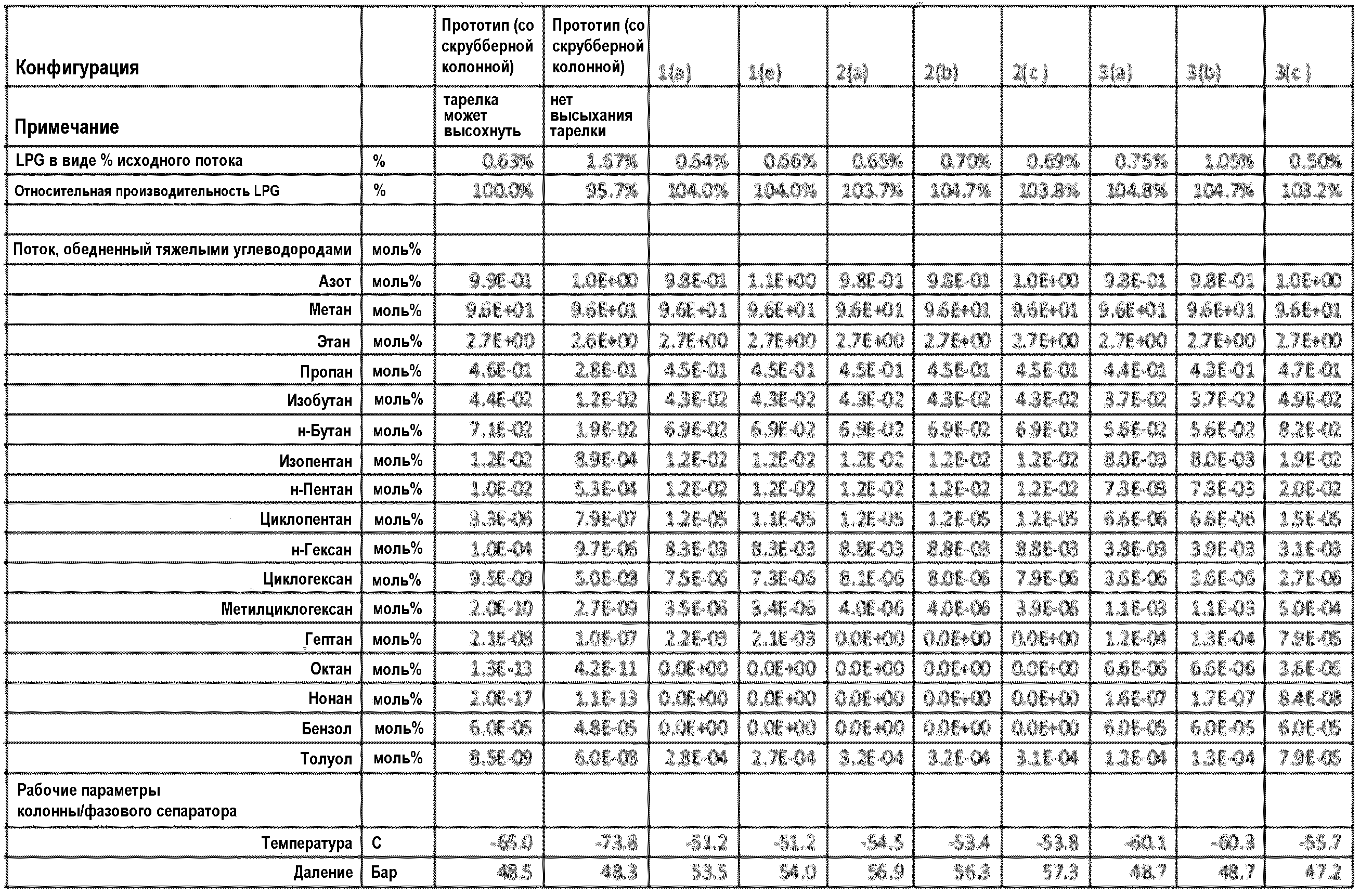
Должно быть отмечено, что изобретение не ограничивается подробностями, описанными выше в отношении предпочтительных вариантов, но что многочисленные модификации и вариации могут быть сделаны без отступления от сущности и объема изобретения, как определено в нижеследующей формуле изобретения.It should be noted that the invention is not limited to the details described above in relation to the preferred options, but that numerous modifications and variations can be made without departing from the essence and scope of the invention, as defined in the following claims.
Claims (12)
охлаждения исходного потока природного газа;
введения охлажденного исходного потока природного газа в систему разделения газ-жидкость и разделения охлажденного исходного потока природного газа на паровой поток природного газа, обедненного тяжелыми углеводородами, и на поток жидкости, обогащенной тяжелыми углеводородами;
нагревания парового потока природного газа, обедненного тяжелыми углеводородами;
пропускания по меньшей мере части парового потока природного газа, обедненного тяжелыми углеводородами, через один или несколько слоев адсорбционной системы для адсорбирования из него тяжелых углеводородов с получением таким образом потока природного газа, обедненного тяжелыми углеводородами; и
охлаждения по меньшей мере части потока природного газа, обедненного тяжелыми углеводородами, с получением охлажденного потока природного газа, обедненного тяжелыми углеводородами;
где паровой поток природного газа, обедненный тяжелыми углеводородами, нагревают и по меньшей мере часть потока природного газа, обедненного тяжелыми углеводородами, охлаждают в экономайзере-теплообменнике путем косвенного теплообмена между исходным паровым потоком природного газа, обедненного тяжелыми углеводородами, и по меньшей мере части потока природного газа, обедненного тяжелыми углеводородами.1. A method for removing heavy hydrocarbons from an initial natural gas stream, comprising the steps of:
cooling the natural gas feed stream;
introducing the cooled natural gas feed stream into a gas-liquid separation system and separating the cooled natural gas feed stream into a heavy hydrocarbon depleted natural gas vapor stream and a heavy hydrocarbon rich liquid stream;
heating a steam stream of natural gas depleted in heavy hydrocarbons;
passing at least a portion of the heavy hydrocarbon depleted steam stream of natural gas through one or more layers of an adsorption system to adsorb heavy hydrocarbons therefrom, thereby producing a heavy hydrocarbon depleted natural gas stream; and
cooling at least a portion of the heavy hydrocarbon depleted natural gas stream to produce a cooled heavy hydrocarbon depleted natural gas stream;
where the vapor stream of natural gas depleted in heavy hydrocarbons is heated and at least a portion of the stream of natural gas depleted in heavy hydrocarbons is cooled in an economizer-heat exchanger by indirect heat exchange between the original vapor stream of natural gas depleted in heavy hydrocarbons and at least a portion of the stream of natural gas depleted in heavy hydrocarbons.
систему разделения газ-жидкость для приема и разделения исходного потока природного газа на паровой поток природного газа, обедненного тяжелыми углеводородами, и поток жидкости, обогащенной тяжелыми углеводородами;
адсорбционную систему в проточном текучем сообщении с системой разделения газ-жидкость для приема по меньшей мере части парового потока природного газа, обедненного тяжелыми углеводородами, содержащую один или несколько слоев адсорбента для адсорбирования тяжелых углеводородов из указанной по меньшей мере части парового потока природного газа, обедненного тяжелыми углеводородами, с получением таким образом потока природного газа, обедненного тяжелыми углеводородами;
экономайзер-теплообменник для нагревания парового потока природного газа, обедненного тяжелыми углеводородами, до пропускания указанного потока или его части через один или несколько слоев адсорбционной системы и охлаждения по меньшей мере части потока природного газа, обедненного тяжелыми углеводородами, путем косвенного теплообмена между паровым потоком природного газа, обедненного тяжелыми углеводородами, и по меньшей мере частью потока природного газа, обедненного тяжелыми углеводородами; и
сжижающий аппарат, соединенный в проточном текучем сообщении с системой разделения газ-жидкость и адсорбционной системой, для приема и охлаждения исходного потока природного газа до введения указанного потока в систему разделения газ-жидкость и для приема и сжижения по меньшей мере частью потока природного газа, обедненного тяжелыми углеводородами, с получением потока сжиженного природного газа, где поток природного газа, обедненного тяжелыми углеводородами, вводят в горячий конец сжижающего аппарата и выводят из промежуточного участка сжижающего аппарата, и по меньшей мере часть потока природного газа, обедненного тяжелыми углеводородами, вводят в промежуточный участок сжижающего аппарата и выводят из холодного конца сжижающего аппарата.11. A device for removing heavy hydrocarbons from an initial natural gas stream and producing a liquefied natural gas stream, comprising:
a gas-liquid separation system for receiving and separating a feed stream of natural gas into a steam stream of natural gas depleted in heavy hydrocarbons and a stream of liquid enriched in heavy hydrocarbons;
an adsorption system in fluid flow communication with a gas-liquid separation system for receiving at least a portion of a heavy hydrocarbon depleted natural gas vapor stream containing one or more adsorbent layers for adsorbing heavy hydrocarbons from said at least a heavy depleted natural gas vapor stream hydrocarbons, thereby producing a stream of natural gas depleted in heavy hydrocarbons;
economizer-heat exchanger for heating a steam stream of natural gas depleted in heavy hydrocarbons until the specified stream or part of it passes through one or more layers of the adsorption system and cooling at least part of the stream of natural gas depleted in heavy hydrocarbons by indirect heat exchange between the steam stream of natural gas heavy hydrocarbon depleted and at least part of a heavy hydrocarbon depleted natural gas stream; and
a liquefaction apparatus, connected in a flowing fluid communication with a gas-liquid separation system and an adsorption system, for receiving and cooling a natural gas feed stream before introducing said stream into a gas-liquid separation system and for receiving and liquefying at least a portion of a depleted natural gas stream heavy hydrocarbons, to obtain a stream of liquefied natural gas, where a stream of natural gas depleted in heavy hydrocarbons is introduced into the hot end of the liquefaction apparatus and removed from the intermediate Single fluidizing apparatus, and at least part of the natural gas stream depleted in heavy hydrocarbons, is introduced into the intermediate portion of the fluidizing apparatus and is withdrawn from the cold end of the fluidizing apparatus.
Applications Claiming Priority (7)
| Application Number | Priority Date | Filing Date | Title |
|---|---|---|---|
| US13/565,881 US20140033762A1 (en) | 2012-08-03 | 2012-08-03 | Heavy Hydrocarbon Removal From A Natural Gas Stream |
| US13/565,881 | 2012-08-03 | ||
| PCT/US2012/049506 WO2014021900A1 (en) | 2012-08-03 | 2012-08-03 | Heavy hydrocarbon removal from a natural gas stream |
| USPCT/US2012/049506 | 2012-08-03 | ||
| US13/611,169 US9631864B2 (en) | 2012-08-03 | 2012-09-12 | Heavy hydrocarbon removal from a natural gas stream |
| US13/611,169 | 2012-09-12 | ||
| PCT/US2013/052933 WO2014022510A2 (en) | 2012-08-03 | 2013-07-31 | Heavy hydrocarbon removal from a natural gas stream |
Publications (2)
| Publication Number | Publication Date |
|---|---|
| RU2015107256A RU2015107256A (en) | 2016-09-27 |
| RU2599582C2 true RU2599582C2 (en) | 2016-10-10 |
Family
ID=56291320
Family Applications (1)
| Application Number | Title | Priority Date | Filing Date |
|---|---|---|---|
| RU2015107256/04A RU2599582C2 (en) | 2012-08-03 | 2013-07-31 | Removal of heavy hydrocarbons from natural gas flow |
Country Status (11)
| Country | Link |
|---|---|
| EP (1) | EP2880134B1 (en) |
| JP (1) | JP5956686B2 (en) |
| KR (1) | KR101643110B1 (en) |
| CN (1) | CN104685036B (en) |
| AU (1) | AU2013296552B2 (en) |
| BR (1) | BR112015002328B1 (en) |
| CA (1) | CA2880441C (en) |
| MY (1) | MY176383A (en) |
| PE (1) | PE20150658A1 (en) |
| RU (1) | RU2599582C2 (en) |
| WO (1) | WO2014022510A2 (en) |
Cited By (1)
| Publication number | Priority date | Publication date | Assignee | Title |
|---|---|---|---|---|
| RU2640050C1 (en) * | 2017-02-02 | 2017-12-26 | Публичное акционерное общество криогенного машиностроения (ПАО "Криогенмаш") | Method for removing heavy hydrocarbons when liquefying natural gas and device for its implementation |
Families Citing this family (9)
| Publication number | Priority date | Publication date | Assignee | Title |
|---|---|---|---|---|
| CN104893773B (en) * | 2014-06-20 | 2018-02-23 | 康泰斯(上海)化学工程有限公司 | Pipe natural gas heavy hydrocarbon removal unit and heavy hydrocarbon removal methods |
| CN104990827B (en) * | 2015-06-15 | 2019-02-01 | 北京科技大学 | The measuring method and equipment of low volatility organic gas adsorbance on the adsorbent material |
| KR101733770B1 (en) | 2015-07-08 | 2017-05-08 | 주식회사 케이티 | Private security management apparatus and system for managing security of private terminal using vlan and method thereof |
| US10427089B2 (en) * | 2016-05-31 | 2019-10-01 | Exxonmobil Upstream Research Company | Apparatus and system for swing adsorption processes |
| US11402155B2 (en) | 2016-09-06 | 2022-08-02 | Lummus Technology Inc. | Pretreatment of natural gas prior to liquefaction |
| US10821394B2 (en) * | 2018-06-20 | 2020-11-03 | Uop Llc | Temperature swing adsorption process for heavy hydrocarbon removal |
| US11034903B2 (en) * | 2018-06-27 | 2021-06-15 | Uop Llc | Adsorption process for treating natural gas |
| CN112505161B (en) * | 2020-12-01 | 2022-04-29 | 西南石油大学 | Device and method for measuring content and precipitation amount of aromatic hydrocarbon substances in natural gas |
| WO2023288162A1 (en) | 2021-07-16 | 2023-01-19 | Exxonmobil Upstream Research Company | Methods for operating hydrocarbon removal systems from natural gas streams |
Citations (4)
| Publication number | Priority date | Publication date | Assignee | Title |
|---|---|---|---|---|
| US5451249A (en) * | 1994-06-14 | 1995-09-19 | International Fuel Cells | Landfill gas treatment system |
| WO2005042671A1 (en) * | 2003-10-30 | 2005-05-12 | Shell Internationale Research Maatschappij B.V. | Process and system for removing contaminants from a natural gas stream |
| EA200970972A1 (en) * | 2007-05-18 | 2010-04-30 | Эксонмобил Рисерч Энд Инджиниринг Компани | REMOVAL OF HEAVY HYDROCARBONS FROM GAS MIXTURES CONTAINING HEAVY HYDROCARBONS AND METHANES |
| WO2011097162A1 (en) * | 2010-02-02 | 2011-08-11 | Linde Aktiengesellschaft | Gas purification processes |
Family Cites Families (19)
| Publication number | Priority date | Publication date | Assignee | Title |
|---|---|---|---|---|
| US3594983A (en) * | 1969-06-17 | 1971-07-27 | Process Services Inc | Gas-treating process and system |
| US3792590A (en) * | 1970-12-21 | 1974-02-19 | Airco Inc | Liquefaction of natural gas |
| GB1419380A (en) | 1972-03-03 | 1975-12-31 | British Gas Corp | Purification of natural gas |
| US5325673A (en) | 1993-02-23 | 1994-07-05 | The M. W. Kellogg Company | Natural gas liquefaction pretreatment process |
| CA2133302A1 (en) | 1993-10-06 | 1995-04-07 | Ravi Kumar | Integrated process for purifying and liquefying a feed gas mixture with respect to its less strongly adsorbed component of lower volatility |
| FR2714722B1 (en) * | 1993-12-30 | 1997-11-21 | Inst Francais Du Petrole | Method and apparatus for liquefying a natural gas. |
| CA2473949C (en) | 2002-01-18 | 2008-08-19 | Robert Amin | Process and device for production of lng by removal of freezable solids |
| AU2003900534A0 (en) * | 2003-02-07 | 2003-02-20 | Shell Internationale Research Maatschappij B.V. | Process and apparatus for removal of a contaminant from a natural gas feed stream |
| US6662589B1 (en) * | 2003-04-16 | 2003-12-16 | Air Products And Chemicals, Inc. | Integrated high pressure NGL recovery in the production of liquefied natural gas |
| US7600395B2 (en) * | 2004-06-24 | 2009-10-13 | Conocophillips Company | LNG system employing refluxed heavies removal column with overhead condensing |
| US7165423B2 (en) | 2004-08-27 | 2007-01-23 | Amec Paragon, Inc. | Process for extracting ethane and heavier hydrocarbons from LNG |
| PE20060989A1 (en) | 2004-12-08 | 2006-11-06 | Shell Int Research | METHOD AND DEVICE FOR PRODUCING A LIQUID NATURAL GAS CURRENT |
| CA2615439C (en) | 2005-07-26 | 2015-04-14 | Exxonmobil Upstream Research Company | Method of purifying hydrocarbons and regeneration of adsorbents used therein |
| FR2921470B1 (en) | 2007-09-24 | 2015-12-11 | Inst Francais Du Petrole | METHOD FOR LIQUEFACTING DRY NATURAL GAS |
| CN201362705Y (en) * | 2009-03-12 | 2009-12-16 | 西安长庆科技工程有限责任公司 | Natural gas water removal and heavy hydrocarbon removal device |
| SG10201403307PA (en) | 2009-07-30 | 2014-10-30 | Exxonmobil Upstream Res Co | Systems and methods for removing heavy hydrocarbons and acid gases from a hydrocarbon gas stream |
| CN202297537U (en) * | 2011-09-30 | 2012-07-04 | 新地能源工程技术有限公司 | Methane gas-rich purification device adopting hydrogen-rich nitrogen gas for precooling |
| CN102643694B (en) * | 2012-04-27 | 2014-12-03 | 新地能源工程技术有限公司 | Technique and device for drying and liquefaction of natural gas |
| US20140033762A1 (en) * | 2012-08-03 | 2014-02-06 | Air Products And Chemicals, Inc. | Heavy Hydrocarbon Removal From A Natural Gas Stream |
-
2013
- 2013-07-31 JP JP2015525542A patent/JP5956686B2/en active Active
- 2013-07-31 CN CN201380051898.9A patent/CN104685036B/en active Active
- 2013-07-31 AU AU2013296552A patent/AU2013296552B2/en active Active
- 2013-07-31 WO PCT/US2013/052933 patent/WO2014022510A2/en active Application Filing
- 2013-07-31 BR BR112015002328-2A patent/BR112015002328B1/en active IP Right Grant
- 2013-07-31 CA CA2880441A patent/CA2880441C/en active Active
- 2013-07-31 EP EP13747599.2A patent/EP2880134B1/en active Active
- 2013-07-31 PE PE2015000131A patent/PE20150658A1/en active IP Right Grant
- 2013-07-31 KR KR1020157005606A patent/KR101643110B1/en active IP Right Grant
- 2013-07-31 RU RU2015107256/04A patent/RU2599582C2/en active
- 2013-07-31 MY MYPI2015700245A patent/MY176383A/en unknown
Patent Citations (4)
| Publication number | Priority date | Publication date | Assignee | Title |
|---|---|---|---|---|
| US5451249A (en) * | 1994-06-14 | 1995-09-19 | International Fuel Cells | Landfill gas treatment system |
| WO2005042671A1 (en) * | 2003-10-30 | 2005-05-12 | Shell Internationale Research Maatschappij B.V. | Process and system for removing contaminants from a natural gas stream |
| EA200970972A1 (en) * | 2007-05-18 | 2010-04-30 | Эксонмобил Рисерч Энд Инджиниринг Компани | REMOVAL OF HEAVY HYDROCARBONS FROM GAS MIXTURES CONTAINING HEAVY HYDROCARBONS AND METHANES |
| WO2011097162A1 (en) * | 2010-02-02 | 2011-08-11 | Linde Aktiengesellschaft | Gas purification processes |
Cited By (1)
| Publication number | Priority date | Publication date | Assignee | Title |
|---|---|---|---|---|
| RU2640050C1 (en) * | 2017-02-02 | 2017-12-26 | Публичное акционерное общество криогенного машиностроения (ПАО "Криогенмаш") | Method for removing heavy hydrocarbons when liquefying natural gas and device for its implementation |
Also Published As
| Publication number | Publication date |
|---|---|
| CA2880441C (en) | 2017-07-18 |
| MY176383A (en) | 2020-08-04 |
| BR112015002328B1 (en) | 2024-01-09 |
| KR101643110B1 (en) | 2016-08-10 |
| EP2880134B1 (en) | 2019-05-15 |
| WO2014022510A2 (en) | 2014-02-06 |
| BR112015002328A2 (en) | 2017-07-04 |
| CN104685036A (en) | 2015-06-03 |
| JP2015531013A (en) | 2015-10-29 |
| KR20150041641A (en) | 2015-04-16 |
| EP2880134A2 (en) | 2015-06-10 |
| WO2014022510A3 (en) | 2014-07-03 |
| RU2015107256A (en) | 2016-09-27 |
| JP5956686B2 (en) | 2016-07-27 |
| AU2013296552A1 (en) | 2015-03-12 |
| PE20150658A1 (en) | 2015-05-11 |
| CA2880441A1 (en) | 2014-02-06 |
| AU2013296552B2 (en) | 2016-09-15 |
| CN104685036B (en) | 2017-07-11 |
Similar Documents
| Publication | Publication Date | Title |
|---|---|---|
| RU2599582C2 (en) | Removal of heavy hydrocarbons from natural gas flow | |
| US9631864B2 (en) | Heavy hydrocarbon removal from a natural gas stream | |
| AU2008213739B2 (en) | Process and apparatus for depleting carbon dioxide content in a natural gas feedstream containing ethane and C3+ hydrocarbons | |
| JP5997798B2 (en) | Nitrogen removal by isobaric open frozen natural gas liquid recovery | |
| TWI572405B (en) | Method of separating carbon dioxide from liquid acid gas streams | |
| US7337631B2 (en) | Use of cryogenic temperatures in processing gases containing light components with physical solvents | |
| WO2014021900A1 (en) | Heavy hydrocarbon removal from a natural gas stream | |
| RU2613914C9 (en) | Method for processing natural hydrocarbon gas | |
| EP4313855A1 (en) | Method of recovering a hydrogen-enriched product and co2 in a hydrogen production unit | |
| US20080256977A1 (en) | Hydrocarbon recovery and light product purity when processing gases with physical solvents | |
| US10760010B2 (en) | Methods and systems to separate hydrocarbon mixtures such as natural gas into light and heavy components | |
| RU2225971C1 (en) | Process of separation of accompanying oil gas | |
| US10760006B2 (en) | Methods and systems to separate hydrocarbon mixtures such as natural gas into light and heavy components | |
| Bulkatov | Low-temperature condensation technology in fractionating oil-associated gas | |
| AU2013205633A1 (en) | Process and apparatus for depleting carbon dioxide content in a natural gas feedstream containing ethane and c3+hydrocarbons |