RU2597792C2 - Luminaire emitting light of different colours - Google Patents
Luminaire emitting light of different colours Download PDFInfo
- Publication number
- RU2597792C2 RU2597792C2 RU2014105574/07A RU2014105574A RU2597792C2 RU 2597792 C2 RU2597792 C2 RU 2597792C2 RU 2014105574/07 A RU2014105574/07 A RU 2014105574/07A RU 2014105574 A RU2014105574 A RU 2014105574A RU 2597792 C2 RU2597792 C2 RU 2597792C2
- Authority
- RU
- Russia
- Prior art keywords
- leds
- led
- light
- light source
- lamp
- Prior art date
Links
Images

Classifications
-
- F—MECHANICAL ENGINEERING; LIGHTING; HEATING; WEAPONS; BLASTING
- F21—LIGHTING
- F21K—NON-ELECTRIC LIGHT SOURCES USING LUMINESCENCE; LIGHT SOURCES USING ELECTROCHEMILUMINESCENCE; LIGHT SOURCES USING CHARGES OF COMBUSTIBLE MATERIAL; LIGHT SOURCES USING SEMICONDUCTOR DEVICES AS LIGHT-GENERATING ELEMENTS; LIGHT SOURCES NOT OTHERWISE PROVIDED FOR
- F21K9/00—Light sources using semiconductor devices as light-generating elements, e.g. using light-emitting diodes [LED] or lasers
- F21K9/60—Optical arrangements integrated in the light source, e.g. for improving the colour rendering index or the light extraction
- F21K9/64—Optical arrangements integrated in the light source, e.g. for improving the colour rendering index or the light extraction using wavelength conversion means distinct or spaced from the light-generating element, e.g. a remote phosphor layer
-
- F—MECHANICAL ENGINEERING; LIGHTING; HEATING; WEAPONS; BLASTING
- F21—LIGHTING
- F21S—NON-PORTABLE LIGHTING DEVICES; SYSTEMS THEREOF; VEHICLE LIGHTING DEVICES SPECIALLY ADAPTED FOR VEHICLE EXTERIORS
- F21S8/00—Lighting devices intended for fixed installation
-
- F—MECHANICAL ENGINEERING; LIGHTING; HEATING; WEAPONS; BLASTING
- F21—LIGHTING
- F21V—FUNCTIONAL FEATURES OR DETAILS OF LIGHTING DEVICES OR SYSTEMS THEREOF; STRUCTURAL COMBINATIONS OF LIGHTING DEVICES WITH OTHER ARTICLES, NOT OTHERWISE PROVIDED FOR
- F21V7/00—Reflectors for light sources
- F21V7/04—Optical design
-
- F—MECHANICAL ENGINEERING; LIGHTING; HEATING; WEAPONS; BLASTING
- F21—LIGHTING
- F21V—FUNCTIONAL FEATURES OR DETAILS OF LIGHTING DEVICES OR SYSTEMS THEREOF; STRUCTURAL COMBINATIONS OF LIGHTING DEVICES WITH OTHER ARTICLES, NOT OTHERWISE PROVIDED FOR
- F21V29/00—Protecting lighting devices from thermal damage; Cooling or heating arrangements specially adapted for lighting devices or systems
- F21V29/50—Cooling arrangements
- F21V29/70—Cooling arrangements characterised by passive heat-dissipating elements, e.g. heat-sinks
- F21V29/74—Cooling arrangements characterised by passive heat-dissipating elements, e.g. heat-sinks with fins or blades
-
- F—MECHANICAL ENGINEERING; LIGHTING; HEATING; WEAPONS; BLASTING
- F21—LIGHTING
- F21V—FUNCTIONAL FEATURES OR DETAILS OF LIGHTING DEVICES OR SYSTEMS THEREOF; STRUCTURAL COMBINATIONS OF LIGHTING DEVICES WITH OTHER ARTICLES, NOT OTHERWISE PROVIDED FOR
- F21V29/00—Protecting lighting devices from thermal damage; Cooling or heating arrangements specially adapted for lighting devices or systems
- F21V29/85—Protecting lighting devices from thermal damage; Cooling or heating arrangements specially adapted for lighting devices or systems characterised by the material
- F21V29/89—Metals
-
- F—MECHANICAL ENGINEERING; LIGHTING; HEATING; WEAPONS; BLASTING
- F21—LIGHTING
- F21V—FUNCTIONAL FEATURES OR DETAILS OF LIGHTING DEVICES OR SYSTEMS THEREOF; STRUCTURAL COMBINATIONS OF LIGHTING DEVICES WITH OTHER ARTICLES, NOT OTHERWISE PROVIDED FOR
- F21V7/00—Reflectors for light sources
- F21V7/04—Optical design
- F21V7/048—Optical design with facets structure
-
- F—MECHANICAL ENGINEERING; LIGHTING; HEATING; WEAPONS; BLASTING
- F21—LIGHTING
- F21Y—INDEXING SCHEME ASSOCIATED WITH SUBCLASSES F21K, F21L, F21S and F21V, RELATING TO THE FORM OR THE KIND OF THE LIGHT SOURCES OR OF THE COLOUR OF THE LIGHT EMITTED
- F21Y2113/00—Combination of light sources
- F21Y2113/10—Combination of light sources of different colours
- F21Y2113/13—Combination of light sources of different colours comprising an assembly of point-like light sources
-
- F—MECHANICAL ENGINEERING; LIGHTING; HEATING; WEAPONS; BLASTING
- F21—LIGHTING
- F21Y—INDEXING SCHEME ASSOCIATED WITH SUBCLASSES F21K, F21L, F21S and F21V, RELATING TO THE FORM OR THE KIND OF THE LIGHT SOURCES OR OF THE COLOUR OF THE LIGHT EMITTED
- F21Y2113/00—Combination of light sources
- F21Y2113/20—Combination of light sources of different form
-
- F—MECHANICAL ENGINEERING; LIGHTING; HEATING; WEAPONS; BLASTING
- F21—LIGHTING
- F21Y—INDEXING SCHEME ASSOCIATED WITH SUBCLASSES F21K, F21L, F21S and F21V, RELATING TO THE FORM OR THE KIND OF THE LIGHT SOURCES OR OF THE COLOUR OF THE LIGHT EMITTED
- F21Y2115/00—Light-generating elements of semiconductor light sources
- F21Y2115/10—Light-emitting diodes [LED]
-
- G—PHYSICS
- G02—OPTICS
- G02B—OPTICAL ELEMENTS, SYSTEMS OR APPARATUS
- G02B27/00—Optical systems or apparatus not provided for by any of the groups G02B1/00 - G02B26/00, G02B30/00
- G02B27/10—Beam splitting or combining systems
- G02B27/14—Beam splitting or combining systems operating by reflection only
Abstract
Description
ОБЛАСТЬ ТЕХНИКИFIELD OF TECHNOLOGY
Настоящее изобретение относится к области светильников, а точнее говоря, к светильнику, содержащему матрицу СИД, содержащую, по меньшей мере, один тип СИД из группы синих СИД, зеленых СИД, красных СИД, желтых СИД, СИД янтарного цвета, голубых СИД и белых СИД.The present invention relates to the field of luminaires, and more specifically, to a luminaire containing an LED array comprising at least one type of LED from the group of blue LEDs, green LEDs, red LEDs, yellow LEDs, amber LEDs, blue LEDs and white LEDs .
УРОВЕНЬ ТЕХНИКИBACKGROUND
Окрашенный свет используют во многих применениях, где важна установка сцены и создание атмосферы. Примерами применений является освещение в театре, архитектурное освещение (украшение города), освещение магазинов и представительские мероприятия (украшение отелей, ресторанов). В настоящее время это осуществляется в основном за счет комбинирования источников белого света с цветными фильтрами.Colored light is used in many applications where setting the scene and creating the atmosphere is important. Examples of applications are theater lighting, architectural lighting (city decoration), store lighting and entertainment (hotel decoration, restaurant decoration). Currently, this is mainly done by combining white light sources with color filters.
В качестве альтернативы, могут быть использованы системы с многоцветными СИД (светоизлучающими диодами). Они являются привлекательными, поскольку они генерируют цвета в отсутствие фильтров. Это дает преимущество в эффективности и, что более важно, цвета можно изменять с помощью электронной аппаратуры: отпадает необходимость в замене фильтров для изменения цвета и все цвета становятся доступными всегда. Рынок этих систем быстро растет с повышением рабочих характеристик СИД. Недостатком является то, что трудно получить спектр света, который имитирует спектр света, испускаемого галогеновыми лампами.Alternatively, systems with multi-color LEDs (light emitting diodes) can be used. They are attractive because they generate colors in the absence of filters. This gives an advantage in efficiency and, more importantly, colors can be changed using electronic equipment: there is no need to replace filters to change colors and all colors are always available. The market for these systems is growing rapidly with improved LED performance. The disadvantage is that it is difficult to obtain a spectrum of light that mimics the spectrum of light emitted by halogen lamps.
СУЩНОСТЬ ИЗОБРЕТЕНИЯSUMMARY OF THE INVENTION
Задачей настоящего изобретения является преодоление или смягчение проблем, известных из уровня техники.An object of the present invention is to overcome or mitigate problems known in the art.
Согласно первой особенности изобретения эта и другие задачи достигаются с помощью светильника, содержащего матрицу СИД, содержащих, по меньшей мере, одну из групп, состоящую из синих СИД, зеленых СИД, красных СИД, желтых СИД, СИД янтарного цвета, голубых СИД и белых СИД, отражательную трубку, имеющую входную апертуру, выходную апертуру, отражающую периферийную стенку, простирающуюся между упомянутыми апертурами, и оптическую ось, простирающуюся между упомянутыми апертурами по центру относительно упомянутой стенки, причем упомянутая матрица СИД расположена в упомянутой входной апертуре, упомянутая периферийная стенка расположена таким образом, чтобы она отражала и смешивала свет, исходящий из упомянутой матрицы СИД, причем, по меньшей мере, один источник света расположен периферийно вокруг упомянутой отражательной трубки, и при этом, по меньшей мере, один источник света содержит, по меньшей мере, один СИД, выбранный из группы темно-синих СИД, ярко-синих СИД, темно-красных СИД и ультрафиолетовых СИД, и, по меньшей мере, один оптический компонент расположен для пропускания света, испускаемого, по меньшей мере, из одного источника света к свету, испускаемому из матрицы СИД.According to a first aspect of the invention, this and other tasks are achieved by means of a luminaire comprising an LED array comprising at least one of the groups consisting of blue LEDs, green LEDs, red LEDs, yellow LEDs, amber LEDs, blue LEDs and white LEDs a reflective tube having an input aperture, an output aperture reflecting a peripheral wall extending between said apertures, and an optical axis extending between said apertures in the center relative to said wall, said matrix The LED is located in said input aperture, said peripheral wall is arranged so that it reflects and mixes the light emitted from said LED matrix, at least one light source being peripherally around said reflective tube, and at least at least one light source contains at least one LED selected from the group of dark blue LEDs, bright blue LEDs, dark red LEDs and ultraviolet LEDs, and at least one optical component is arranged to transmit light the one emitted from the at least one light source to the light emitted from the LED array.
Преимущество этого состоит в том, что качество воспроизведения цвета спектра излучаемого света повышается, благодаря большому количеству СИД, испускающих свет при различных длинах волн. Кроме того, можно использовать большее количество СИД, поскольку не все СИД должны быть расположены во входной апертуре, но некоторые из них могут быть расположены по периферии вокруг отражательной трубки. Большее количество СИД приводит к большему выходу света. Меньшее количество СИД на ограниченной области внутри входной апертуры приводит к меньшему количеству генерируемого тепла внутри отражательной трубки. Более того, достигается смешивание различного света, что приводит к равномерному распределению света и снижению риска затемнения света. Источник света относительно мал, благодаря компактной конструкции, что приводит к четко определенному пучку света, что подразумевает, что светильник может быть использован, например, в прожекторах бокового освещения.The advantage of this is that the color reproduction quality of the spectrum of the emitted light is enhanced due to the large number of LEDs emitting light at different wavelengths. In addition, you can use a larger number of LEDs, since not all LEDs should be located in the input aperture, but some of them may be located on the periphery around the reflective tube. More LEDs result in more light output. Fewer LEDs in a limited area inside the input aperture result in less heat being generated inside the reflector tube. Moreover, mixing of different light is achieved, which leads to a uniform distribution of light and a reduced risk of darkening of the light. The light source is relatively small, due to its compact design, which leads to a well-defined beam of light, which implies that the lamp can be used, for example, in sidelights.
Упомянутый оптический компонент может представлять собой X-куб, расположенный у выходной апертуры, вследствие чего свет, испускаемый, по меньшей мере, из одного источника света, направляется к свету, испускаемому из матрицы СИД. Преимущество этого состоит в том, что достигается даже более равномерное распределение света.Said optical component may be an X-cube located at the output aperture, whereby the light emitted from at least one light source is directed to the light emitted from the LED matrix. The advantage of this is that an even more uniform distribution of light is achieved.
Упомянутый оптический компонент может представлять собой дихроичное зеркало, которое встроено в упомянутую стенку, прозрачное для света, испускаемого, по меньшей мере, из одного источника света, и отражающее для света, испускаемого из упомянутой матрицы СИД. Преимущество этого состоит в том, что достигается даже более равномерное распределение света.Said optical component may be a dichroic mirror which is embedded in said wall, transparent to light emitted from at least one light source, and reflective to light emitted from said LED matrix. The advantage of this is that an even more uniform distribution of light is achieved.
Дихроичное зеркало может быть расположено ближе к входной апертуре, чем к выходной апертуре. Преимущество этого состоит в том, что достигается лучшее смешивание света и более равномерное распределение света. По меньшей мере, один источник света может быть расположен в смесительной камере. Преимущество этого состоит в том, что свет, испускаемый из источника света, смешивается даже лучше.The dichroic mirror can be located closer to the input aperture than to the output aperture. The advantage of this is that a better mixing of the light and a more even distribution of light is achieved. At least one light source may be located in the mixing chamber. The advantage of this is that the light emitted from the light source mixes even better.
Свет, испускаемый, по меньшей мере, из одного источника света, может быть направлен, по меньшей мере, на одно дихроичное зеркало через зеркало. Преимущество этого состоит в том, что, по меньшей мере, один источник света может быть установлен в той же плоскости, что и упомянутая матрица СИД.The light emitted from at least one light source may be directed to at least one dichroic mirror through the mirror. An advantage of this is that at least one light source can be mounted in the same plane as said LED matrix.
Упомянутый, по меньшей мере, один оптический компонент может представлять собой световод, имеющий входную апертуру и выходную апертуру, в котором входная апертура связана, по меньшей мере, с одним источником света, а выходная апертура световода представляет собой дихроичное зеркало, которое является прозрачным для света, испускаемого, по меньшей мере, из одного источника света, и отражающим для света, испускаемого из упомянутой матрицы СИД, и при этом выходная апертура световода встроена в упомянутую стенку. Преимущество этого состоит в том, что, по меньшей мере, один источник света может быть установлен на расстоянии от отражательной трубки, без допущения существенных потерь в количестве света, испускаемого, по меньшей мере, из одного источника света.The at least one optical component may be a fiber having an input aperture and an output aperture, in which the input aperture is connected to at least one light source, and the output aperture of the fiber is a dichroic mirror that is transparent to light emitted from at least one light source and reflective to light emitted from said LED matrix, and wherein the output aperture of the light guide is embedded in said wall. The advantage of this is that at least one light source can be installed at a distance from the reflective tube, without allowing significant losses in the amount of light emitted from the at least one light source.
Упомянутый, по меньшей мере, один оптический компонент может представлять собой световод, имеющий входную апертуру и выходную апертуру, в котором входная апертура связана, по меньшей мере, с одним источником света, а выходная апертура расположена в упомянутой матрице СИД. Преимущество этого состоит в том, что, по меньшей мере, один источник света может быть установлен на расстоянии от отражательной трубки, без допущения существенных потерь в количестве света, испускаемого, по меньшей мере, из одного источника света.Said at least one optical component may be a light guide having an input aperture and an output aperture, in which the input aperture is connected to at least one light source and the output aperture is located in said LED matrix. The advantage of this is that at least one light source can be installed at a distance from the reflective tube, without allowing significant losses in the amount of light emitted from the at least one light source.
Периферийная стенка может представлять собой, по меньшей мере, периферийную стенку из группы зеркально отражающих или диффузно отражающих периферийных стенок. Преимущество этого состоит в том, что распределение света можно, таким образом, сделать более однородным с точки зрения яркости.The peripheral wall may be at least a peripheral wall from the group of specularly or diffusely reflecting peripheral walls. The advantage of this is that the distribution of light can thus be made more uniform in terms of brightness.
Упомянутая периферийная стенка, если смотреть со стороны упомянутой оптической оси, может иметь выгнутую форму. Преимущество этого состоит в том, что достигается лучшее смешивание света.Said peripheral wall, when viewed from the side of said optical axis, may have a curved shape. The advantage of this is that better light mixing is achieved.
Упомянутая матрица СИД и упомянутый, по меньшей мере, один источник света могут быть расположены на отдельных печатных платах (PCBs, Printed Circuit Boards). Преимущество этого состоит в том, что, по меньшей мере, один источник света можно поддерживать при пониженной температуре, что может повысить эффективность, по меньшей мере, одного источника света.Said LED matrix and said at least one light source may be located on separate printed circuit boards (PCBs, Printed Circuit Boards). The advantage of this is that at least one light source can be maintained at a reduced temperature, which can increase the efficiency of at least one light source.
СИД, расположенные на отдельных печатных платах, могут содержать СИД на основе InGaN или СИД на основе AlInGaP. СИД на основе InGaN могут функционировать при более высоких температурах перехода, чем СИД на основе AlInGaP. Если они оба расположены на одной печатной плате, оба этих типа будут иметь примерно равные температуры, и, следовательно, СИД на основе InGaN нельзя будет использовать при их максимальной мощности. Помещение их на отдельные печатные платы способствует более жесткому управлению СИД на основе InGaN, чем СИД на основе AlInGaP. Отличительным свойством AlInGaP является то, что его максимальная рабочая температура является более низкой, чем у InGaN. Таким образом, температура СИД на основе InGaN может быть более высокой, что приводит к большей мощности и большему количеству испускаемого света. В то же время температуру AlInGAaP можно поддерживать при более низких значениях, что повышает эффективность, например, красных, темно-красных СИД и СИД янтарного цвета.LEDs located on separate circuit boards may include InGaN-based LEDs or AlInGaP-based LEDs. InGaN-based LEDs can operate at higher transition temperatures than AlInGaP-based LEDs. If they are both located on the same PCB, both of these types will have approximately equal temperatures, and therefore, InGaN-based LEDs cannot be used at their maximum power. Placing them on separate circuit boards contributes to tighter control of LEDs based on InGaN than LEDs based on AlInGaP. A distinctive feature of AlInGaP is that its maximum operating temperature is lower than that of InGaN. Thus, the temperature of the InGaN-based LEDs can be higher, which leads to more power and more emitted light. At the same time, AlInGAaP temperature can be maintained at lower values, which increases the efficiency of, for example, red, dark red LEDs and amber LEDs.
По меньшей мере, один оптический компонент может иметь переход из отражающего в пропускающее состояние в диапазоне длин волн 550 и 590 нм. СИД на основе InGaN существуют при различных перекрывающихся диапазонах длин волн, но они не являются эффективными при длинах волн более 550 нм. СИД на основе AlInGaP также существуют при различных перекрывающихся диапазонах длин волн, но они не являются эффективными при длинах волн менее 590 нм. Это означает, что при использовании люминофоров имеет место запрещенная зона в спектре. Оптический компонент, например, дихроичное зеркало и/или Х-куб также привносит диапазон длин волн, в котором отражение и пропускание (переход из отражающего в пропускающее состояние) не являются оптимальными. Таким образом, предпочтительным является конструирование таких дихроичных зеркал, чтобы эти два диапазона совпадали. Следует отметить, что изобретение относится ко всем возможным сочетаниям признаков, перечисленных в формуле изобретения.At least one optical component may have a transition from reflecting to transmitting state in the wavelength range of 550 and 590 nm. InGaN-based LEDs exist at different overlapping wavelength ranges, but they are not effective at wavelengths greater than 550 nm. AlInGaP-based LEDs also exist at different overlapping wavelength ranges, but they are not effective at wavelengths less than 590 nm. This means that when using phosphors, the band gap in the spectrum takes place. The optical component, for example, a dichroic mirror and / or X-cube also introduces a wavelength range in which reflection and transmission (transition from reflecting to transmitting state) are not optimal. Thus, it is preferable to design such dichroic mirrors so that these two ranges coincide. It should be noted that the invention relates to all possible combinations of features listed in the claims.
КРАТКОЕ ОПИСАНИЕ ЧЕРТЕЖЕЙBRIEF DESCRIPTION OF THE DRAWINGS
Эта и другие особенности настоящего изобретения будет описано более подробно, со ссылкой на прилагаемые чертежи, показывающие варианты воплощения изобретения, на которых:This and other features of the present invention will be described in more detail with reference to the accompanying drawings, showing embodiments of the invention, in which:
Фиг. 1 представляет собой перспективное изображение схематической иллюстрации варианта воплощения изобретенного светильника.FIG. 1 is a perspective view of a schematic illustration of an embodiment of the invented lamp.
Фиг. 2 представляет собой перспективное изображение варианта воплощения отражателя, используемого в изобретенном светильнике.FIG. 2 is a perspective view of an embodiment of a reflector used in the invented luminaire.
Фиг. 3 представляет собой вид сбоку схематической иллюстрации варианта воплощения изобретенного светильника.FIG. 3 is a side view of a schematic illustration of an embodiment of the invented lamp.
Фиг. 4 представляет собой вид схематической иллюстрации варианта воплощения изобретенного светильника.FIG. 4 is a schematic illustration of an embodiment of the invented lamp.
Фиг. 5 представляет собой вид схематической иллюстрации варианта воплощения изобретенного светильника.FIG. 5 is a schematic illustration of an embodiment of the invented lamp.
Фиг. 6 представляет собой вид схематической иллюстрации варианта воплощения изобретенного светильника.FIG. 6 is a schematic illustration of an embodiment of the invented lamp.
Фиг. 7 представляет собой вид схематической иллюстрации варианта воплощения изобретенного светильника.FIG. 7 is a schematic illustration of an embodiment of the invented lamp.
Фиг. 8 представляет собой вид сбоку схематической иллюстрации варианта воплощения изобретенного светильника.FIG. 8 is a side view of a schematic illustration of an embodiment of the invented lamp.
ПОДРОБНОЕ ОПИСАНИЕDETAILED DESCRIPTION
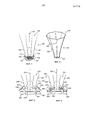
Фиг. 1 представляет собой перспективное изображение схематической иллюстрации варианта воплощения изобретенного светильника. Светильник 100 содержит матрица СИД 120, содержащий, по меньшей мере, один тип СИД из группы синих СИД, зеленых СИД, красных СИД, желтых СИД, СИД янтарного цвета, голубых СИД и белых СИД. Светильник 100 дополнительно содержит отражательную трубку 140, имеющую входную апертуру 142, выходную апертуру 146, отражающую периферийную стенку 148, простирающуюся между упомянутыми апертурами 142, 146, и оптическую ось 150, простирающаяся между упомянутыми апертурами 142, 146 центрально относительно упомянутой стенки 148. Матрица СИД 120 установлена во входной апертуре 142. Периферийная стенка 148 установлена таким образом, чтобы она отражала и смешивала свет, исходящий из матрицы СИД 120.FIG. 1 is a perspective view of a schematic illustration of an embodiment of the invented lamp. The
Два источника света 160 установлены друг напротив друга по периферии вокруг отражательной трубки 140. Каждый из источников света 160 содержит один СИД, выбранный из группы темно-синих СИД, ярко-синих СИД, темно-красных СИД и ультрафиолетовых СИД.Two
Длина волны света, испускаемого из ультрафиолетовых СИД, может находиться в диапазоне 300-500 нм, предпочтительно, 340-450 нм, наиболее предпочтительно, 360-410 нм.The wavelength of light emitted from ultraviolet LEDs can be in the range of 300-500 nm, preferably 340-450 nm, most preferably 360-410 nm.
Длина волны света, испускаемого из темно-красных СИД, может находиться в диапазоне 640-750 нм, предпочтительно, 650-700 нм, наиболее предпочтительно, 660-690 нм.The wavelength of light emitted from the dark red LEDs can be in the range of 640-750 nm, preferably 650-700 nm, most preferably 660-690 nm.
Длина волны света, испускаемого из темно-синих СИД, могут находиться в диапазоне 400-470 нм, предпочтительно, 420-460 нм, наиболее предпочтительно, 430-450 нм.The wavelength of the light emitted from the dark blue LEDs can be in the range of 400-470 nm, preferably 420-460 nm, most preferably 430-450 nm.
Два оптических компонента 170 устанавливают для пропускания света, испускаемого из источников света 160, к свету, испускаемому из матрицы СИД 120. Оптические компоненты 170 устанавливают на той же высоте, что и источники света 160 относительно оптической оси 150. В данном варианте воплощения оптические компоненты 170 представляют собой два дихроичных зеркала, которые являются прозрачными для света, испускаемого из источников света 160, и отражающими для света, испускаемого из матрицы СИД 120. Точнее говоря, дихроичные зеркала могут быть пропускающими для света, испускаемого из источников света 160, который падает под небольшим углом относительно поверхности, нормальной к дихроичным зеркалам, и отражающими для света, испускаемого из матрицы СИД 120, который падает под большим углом относительно поверхности, нормальной к дихроичным зеркалам. Источники света 160 могут иметь оптические элементы, коллимирующие свет, испускаемый из источников света 160. Источники света 160 должны быть расположены таким образом, чтобы свет, испускаемый из источников света 160, падал на дихроичные зеркала 170. Как это проиллюстрировано на Фиг. 1, дихроичные зеркала 170 расположены ближе к входной апертуре 142, чем к выходной апертуре 146.Two
Фиг. 2 представляет собой перспективное изображение варианта воплощения отражателя, используемого в изобретенном светильнике. Отражательная трубка 240 содержит отражающую периферийную стенку 248, простирающуюся между входной апертурой 242 и выходной апертурой 246. Как видно из Фиг. 2, периферийная стенка 248 отклоняется от входной апертуры 242 к выходной апертуре 246. Периферийная стенка 248, если смотреть со стороны упомянутой оптической оси 250, имеет выгнутую форму. Периферийная стенка 248 может представлять собой, по меньшей мере, периферийную стенку из группы зеркально отражающих или диффузно отражающих периферийных стенок. Кроме того, периферийная стенка отражательной трубки может быть сегментированной. Следует отметить, что отражательная трубка 240 может быть использована в вариантах воплощения согласно Фиг. 1, а также 3-8. FIG. 2 is a perspective view of an embodiment of a reflector used in the invented luminaire. The
Фиг. 3 представляет собой вид сбоку схематической иллюстрации варианта воплощения изобретенного светильника. Фиг. 3 раскрывает светильник 300, содержащий матрицу СИД 320, содержащих, по меньшей мере, один тип СИД из группы синих СИД, зеленых СИД, красных СИД, желтых СИД, СИД янтарного цвета, голубых СИД и белых СИД. Светильник 300 дополнительно содержит отражательную трубку 340, имеющую входную апертуру 342, выходную апертуру 346, отражающую периферийную стенку 348, простирающуюся между упомянутыми апертурами 342, 346, и оптическую ось 350, простирающуюся между упомянутыми апертурами 342, 346 центрально относительно упомянутой стенки 348. Матрица СИД 320 установлена во входной апертуре 342. Периферийная стенка 348 установлена таким образом, чтобы она отражала и смешивала свет, исходящий из матрицы СИД 320.FIG. 3 is a side view of a schematic illustration of an embodiment of the invented lamp. FIG. 3 discloses a
Два источника света 360 расположены друг напротив друга, по периферии вокруг отражательной трубки 340. Каждый из источников света 360 содержит два СИД, в которых, по меньшей мере, один СИД выбран из группы темно-синих СИД, ярко-синих СИД, темно-красных СИД и ультрафиолетовых СИД. Здесь также применимы диапазоны длин волн, описанные применительно к Фиг. 1. Источники света 360 расположены рядом с матрицей СИД 320. Источники света 360 расположены относительно матрицы СИД 320 таким образом, чтобы свет, испускаемый из источников света 360, был в основном ориентирован в том же направлении, что и свет, испускаемый из матрицы СИД 320. Поэтому, два зеркала 380 расположены таким образом, чтобы они могли направлять свет, испускаемый из источников света 360, к дихроичным зеркалам 370. The two
Два оптических компонента 370 установлены для пропускания света, испускаемого из источников света 360, к свету, испускаемому из матрицы СИД 320. В данном варианте воплощения оптические компоненты 370 представляют собой два дихроичных зеркала, которые являются прозрачными для света, испускаемого из источников света 360, и отражающими для света, испускаемого из матрицы СИД 320. Как проиллюстрировано на Фиг. 3, дихроичные зеркала 370 расположены ближе к входной апертуре 342, чем к выходной апертуре 346.Two
Фиг. 4 представляет собой вид сбоку схематической иллюстрации варианта воплощения изобретенного светильника. Фиг. 4 раскрывает светильник 400, содержащий матрицу СИД 420, содержащий, по меньшей мере, один тип СИД из группы синих СИД, зеленых СИД, красных СИД, желтых СИД, СИД янтарного цвета, голубых СИД и белых СИД. Светильник 400 дополнительно содержит отражательную трубку 440 имеющую входную апертуру 442, выходную апертуру 446, отражающую периферийную стенку 448, простирающуюся между упомянутыми апертурами 442, 446, и оптическую ось 450, простирающуюся между упомянутыми апертурами 442, 446 центрально относительно упомянутой стенки 448. Матрица СИД 420 установлена во входной апертуре 442. Периферийная стенка 448 установлена таким образом, чтобы она отражала и смешивала свет, исходящий из матрицы СИД 420.FIG. 4 is a side view of a schematic illustration of an embodiment of the invented lamp. FIG. 4 discloses a
Два источника света 460 расположены друг напротив друга по периферии вокруг отражательной трубки 440. Каждый из источников света 4 60 содержит два СИД, из которых, по меньшей мере, один СИД выбран из группы темно-синих СИД, ярко-синих СИД, темно-красных СИД и ультрафиолетовых СИД. Также здесь применимы диапазоны длин волн, описанные применительно к Фиг. 1. Источники света 460 расположены рядом с матрицей СИД 420. Источники света 460 расположены относительно матрицы СИД 420 таким образом, чтобы свет, испускаемый из источников света 460, был в основном ориентирован в том же направлении, что и свет, испускаемый из матрицы СИД 420.Two
Два оптических компонента 470 установлены для пропускания света, испускаемого из источников света 460, к свету, испускаемому из матрицы СИД 420. В данном варианте воплощения, оптические компоненты 470 представляют собой два дихроичных зеркала, которые являются прозрачными для света, испускаемого из источников света 460 и отражающими для света, испускаемого из матрицы СИД 320. Является предпочтительным, чтобы дихроичные зеркала были прозрачными, в широком угловом диапазоне, для света, испускаемого из источников света 460. Каждый из источников света 460 установлен в смесительной камере 480. Смесительная камера обычно также называется диффузной (белой) камерой. Смесительные камеры 480 расположены таким образом, чтобы они могли направлять свет из источников света 460 к дихроичным зеркалам 470. Свет, испускаемый из источников света 480, который падает на стенку смесительных камер 480, которая находится рядом с дихроичными зеркалами 470, пропускается. Свет, испускаемый из источников света 480, который падает на любую из других стенок смесительных камер 480, отражается.Two
Как проиллюстрировано на Фиг. 4, дихроичные зеркала 470 расположены ближе к входной апертуре 442, чем к выходной апертуре 446.As illustrated in FIG. 4,
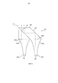
Фиг. 5 представляет собой вид сбоку схематической иллюстрации варианта воплощения изобретенного светильника. Светильник 500 содержит две отражательные трубки 540а и 540b. Во входной апертуре 542а отражательная трубка 540а представляет собой матрицу СИД 520, установленную таким образом, чтобы она содержала, по меньшей мере, один тип СИД из группы синих СИД, зеленых СИД, красных СИД, желтых СИД, СИД янтарного цвета, голубых СИД и белых СИД. Во входной апертуре 542b отражательная трубка 540b представляет собой, по меньшей мере, один источник света 560, установленный таким образом, чтобы он содержал, по меньшей мере, один СИД, причем, по меньшей мере, один СИД выбран из группы темно-синих СИД, ярко-синих СИД, темно-красных СИД и ультрафиолетовых СИД. Здесь также применимы диапазоны длин волн, описанные применительно к Фиг. 1.FIG. 5 is a side view of a schematic illustration of an embodiment of the invented lamp. The
Х-куб 570 устанавливают у выходных апертур 546а и 546b отражательных трубок 540а и 540b. Х-куб представляет собой поперечную дихроичную призму и сочетание четырех треугольных призм. Она функционирует таким образом, чтобы комбинировать несколько цветовых лучей. Прерывистые линии в Х-кубе 570 представляют собой рассеиватели, расположенные у выходных апертур 546а и b. В качестве альтернативы, рассеиватель (не показан) может быть установлен у выходной апертуры 580 светильника 500. An
Свет, испускаемый из матрицы СИД 520, проходит через отражательную трубку 540а, подвергается коллимированию и направляется к Х-кубу 570. Дихроичное зеркало 576 является практически прозрачным для света, испускаемого из матрицы СИД 520, и отражающим для света, испускаемого, по меньшей мере, из одного источника света 560. Таким образом, свет, испускаемый из матрицы СИД 520, проходит через дихроичное зеркало 576 и выходит в виде коллимированного пучка.The light emitted from the
Свет, испускаемый, по меньшей мере, из одного источника света, 560, проходит через отражательную трубку 540b, коллимируется и направляется к Х-кубу 570. Отражатель 574 для всех длин волн отражает свет и направляет его к дихроичному зеркалу 576. Дихроичное зеркало 576 отражает свет, и свет выходит в виде коллимированного пучка.The light emitted from at least one light source, 560, passes through the
Фиг. 6 представляет собой вид сверху схематической иллюстрации варианта воплощения изобретенного светильника. Каждый из множества источников света 660 содержит множество СИД, выбранных из группы темно-синих СИД, ярко-синих СИД, темно-красных СИД и ультрафиолетовых СИД, расположенных по периферии вокруг отражательной трубки 640, в которой установлена матрица СИД 620. Матрица СИД 620 содержит, по меньшей мере, один тип СИД из группы синих СИД, зеленых СИД, красных СИД, желтых СИД, СИД янтарного цвета, голубых СИД и белых СИД. Следует отметить, что вариант воплощения согласно Фиг. 1, 3, и 4 может быть воплощен, также как и вариант, в котором имеется множество источников света, как проиллюстрировано на Фиг. 6.FIG. 6 is a top view of a schematic illustration of an embodiment of the invented lamp. Each of a plurality of
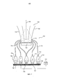
Фиг. 7 представляет собой вид сбоку схематической иллюстрации варианта воплощения изобретенного светильника. Фиг. 7 раскрывает светильник 700, содержащий матрицу СИД 720, содержащую, по меньшей мере, один тип СИД из группы синих СИД, зеленых СИД, красных СИД, желтых СИД, СИД янтарного цвета, голубых СИД и белых СИД. Светильник 700 дополнительно содержит отражательную трубку 740, имеющую входную апертуру 742, выходную апертуру 746, отражающую периферийную стенку 748 простирающуюся между упомянутыми апертурами 742, 746, и оптическую ось 750, простирающуюся между упомянутыми апертурами 742, 746 центрально относительно упомянутой стенки 748. Матрица СИД 720 установлена во входной апертуре 742. Периферийная стенка 748 установлена таким образом, чтобы она отражала и смешивала свет, исходящий из матрицы СИД 720.FIG. 7 is a side view of a schematic illustration of an embodiment of the invented lamp. FIG. 7 discloses a
Множество источников света 760 расположено по периферии вокруг отражательной трубки 740. Источники света 760 содержат, по меньшей мере, один СИД 762, который выбран из группы темно-синих СИД, ярко-синих СИД, темно-красных СИД и ультрафиолетовых СИД. Здесь также применимы диапазоны длин волн, описанные применительно к Фиг. 1. СИД 762 расположены на подложке 766. Подложка 766 обеспечена электрической цепью (не показана) для подачи электроэнергии и любых управляющих сигналов к СИД 762, а также теплопоглощающему устройству 768, с которым СИД 762 термически соединены. Теплопоглощающее устройство 768 адаптировано для рассеяния теплоты, генерируемой СИД 762. В проиллюстрированном случае теплопоглощающее устройство 768 образовано из относительно тонких алюминиевых охлаждающих ребер, установленных на задней стороне подложки 766.A plurality of
Источники света 760 дополнительно содержат множество коллиматоров 764, расположенных наверху каждого СИД 762. Каждый коллиматор 760 установлен для коллимирования света, исходящего из соответствующего СИД 762 в пределах подходящего углового диапазона, обычно менее ±30°, и подходящие области, обычно с диаметром в несколько мм. В качестве примера, коллиматор может представлять собой одноячеечный линзовый концентратор для СИД. Такие линзовые концентраторы, подходящие для стандартных СИД, являются легкодоступными, например, у компании Polymer Optics.The
Оптические компоненты 770 в данном варианте воплощения воплощены в виде гибких оптических волноводов, таких как оптические волокна. Каждый световод 770 имеет входную апертуру 772 и выходную апертуру 774. Выходная апертура 774 представляет собой дихроичное зеркало, прозрачное для света, испускаемого из источников света 760, и отражающее для света, испускаемого из упомянутой матрицы СИД 720. Выходная апертура 774 встроена в упомянутую стенку 748. Входная апертура 772 связана, по меньшей мере, с одним источником света 760. Согласно настоящему изобретению область подложки 766, занимаемая СИД 762, может быть больше, чем выходная апертура 774. Иными словами, световоды 770 собирают свет с большей площади и концентрируют его в меньшей площади выходной апертуры 774. Контроллер цвета 850 может быть установлен для контроля смешивания цветов светильника 700.The
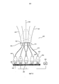
Фиг. 8 представляет собой вид сбоку схематической иллюстрации варианта воплощения изобретенного светильника. Фиг. 8 раскрывает светильник 800, содержащий матрицу СИД 820, содержащую, по меньшей мере, один тип СИД из группы синих СИД, зеленых СИД, красных СИД, желтых СИД, СИД янтарного цвета, голубых СИД и белых СИД. Светильник 800 дополнительно содержит отражательную трубку 840, имеющую входную апертуру 842, выходную апертуру 846, отражающую периферийную стенку 848, простирающуюся между упомянутыми апертурами 842, 846, и оптическую ось 850, простирающуюся между упомянутыми апертурами 842, 846 центрально относительно упомянутой стенки 848. Матрица СИД 820 установлена во входной апертуре 842. Периферийная стенка 848 установлена таким образом, чтобы она отражала и смешивала свет, исходящий из матрицы СИД 820.FIG. 8 is a side view of a schematic illustration of an embodiment of the invented lamp. FIG. 8 discloses a
Множество источников света 860 расположено по периферии вокруг отражательной трубки 840. Источники света 860 содержат, по меньшей мере, один СИД 862, который выбран из группы темно-синих СИД, ярко-синих СИД, темно-красных СИД и ультрафиолетовых СИД. Здесь также применимы диапазоны длин волн, описанные применительно к Фиг. 1. СИД 862 расположены на подложке 866. Подложка 866 обеспечена электрической цепью (не показана) для подачи электроэнергии и любых управляющих сигналов к СИД 862, а также к теплопоглощающему устройству 868, с которым СИД 862 соединены термически. Теплопоглощающее устройство 868 адаптировано для рассеяния тепла, генерируемого СИД 862. В проиллюстрированном случае теплопоглощающее устройство 868 сформировано в виде относительно тонких алюминиевых охлаждающих ребер, расположенных на задней стороне подложки 866. A plurality of
Источники света 860 дополнительно содержат множество коллиматоров 864, установленных наверху каждого СИД 862. Каждый коллиматор 860 установлен для коллимирования света, исходящего из соответствующего СИД 862, в пределах подходящего углового диапазона, обычно менее ±30°, и подходящей области, обычно с диаметром в несколько мм. В качестве примера, коллиматор может представлять собой одноячеечный линзовый концентратор для СИД. Такие линзовые концентраторы, подходящие для стандартных СИД, являются легкодоступными, например, у компании Polymer Optics.The
Оптические компоненты 870 в данном варианте воплощения воплощены в виде гибких оптических волноводов, таких как оптические волокна. Каждый световод 870 имеет входную апертуру 872 и выходную апертуру 874. Входная апертура 872 связана, по меньшей мере, с одним источником света 860. Выходная апертура 874 установлена в упомянутой матрице СИД 820.The
Согласно настоящему изобретению область подложки 866, занимаемая СИД 862, может быть больше, чем выходная апертура 874. Иными словами, световоды 870 собирают свет с большей площади и концентрируют его в меньшей площади выходной апертуры 874. Контроллер цвета 850 может быть установлен для контроля смешивания цветов светильника 700.According to the present invention, the area of the
Как очевидно из Фиг. 1 и 3-8, матрица СИД 120, 320, 420, 520, 620, 720, 820 и, по меньшей мере, один источник света 160, 360, 460, 560, 660, 760, 860 расположены на отдельных печатных платах. СИД, которые расположены на отдельных печатных платах, могут содержать СИД на основе InGaN или СИД на основе AlInGaP. По меньшей мере, один оптический компонент 170, 370, 470, 570, 770 может иметь переход из отражающего в пропускающее состояние в диапазоне длин волн 550-590 нм.As is apparent from FIG. 1 and 3-8, the
В заключение, раскрытые варианты воплощения относятся к светильнику, содержащему матрицу СИД. Матрица СИД содержит СИД, выбранные из группы синих СИД, зеленых СИД, красных СИД, желтых СИД, СИД янтарного цвета, голубых СИД и белых СИД. Светильник дополнительно содержит отражательную трубку, а упомянутая матрица СИД установлена во входной апертуре упомянутой отражательной трубки. По меньшей мере, один источник света установлен по периферии вокруг отражательной трубки. По меньшей мере, один источник света содержит, по меньшей мере, один СИД, выбранный из группы темно-синих СИД, ярко-синих СИД, темно-красных СИД и ультрафиолетовых СИД. Оптический компонент установлен для пропускания света, испускаемого, по меньшей мере, из одного источника света к свету, испускаемому из матрицы СИД.In conclusion, the disclosed embodiments relate to a luminaire comprising an LED array. The LED matrix contains LEDs selected from the group of blue LEDs, green LEDs, red LEDs, yellow LEDs, amber LEDs, blue LEDs and white LEDs. The luminaire further comprises a reflective tube, and said LED matrix is installed in the input aperture of said reflective tube. At least one light source is installed on the periphery around the reflective tube. At least one light source contains at least one LED selected from the group of dark blue LEDs, bright blue LEDs, dark red LEDs and ultraviolet LEDs. The optical component is mounted to transmit light emitted from the at least one light source to light emitted from the LED array.
Притом, что изобретение было проиллюстрировано и подробно описано на чертежах и в вышеприведенном описании, такую иллюстрацию и описание следует рассматривать в качестве иллюстративных или примерных, а не ограничивающих; изобретение не ограничено раскрытыми вариантами воплощения.While the invention has been illustrated and described in detail in the drawings and in the above description, such illustration and description should be considered as illustrative or exemplary, and not limiting; the invention is not limited to the disclosed embodiments.
Другие видоизменения, вносимые в раскрытые варианты воплощения, могут быть поняты и осуществлены специалистами в данной области техники при реализации заявленного изобретения, исходя из изучения чертежей, раскрытия и прилагаемой формулы изобретения. В формуле изобретения слово «содержащий» не исключает других элементов или этапов, а единственное число не исключает множественности.Other modifications to the disclosed embodiments may be understood and carried out by those skilled in the art in the practice of the claimed invention, based on a study of the drawings, disclosure and appended claims. In the claims, the word “comprising” does not exclude other elements or steps, and the singular does not exclude plurality.
Одиночный процессор или другой блок может выполнять функции нескольких объектов, перечисленных в формуле изобретения. Сам факт, что определенные меры перечислены в различных взаимозависимых пунктах формулы изобретения, не указывает на то, что невозможно успешно использовать сочетание этих мер. Никакие ссылочные обозначения в формуле изобретения не следует рассматривать как ограничивающие объем.A single processor or other unit can perform the functions of several objects listed in the claims. The fact that certain measures are listed in various interdependent claims does not indicate that it is not possible to successfully use a combination of these measures. No reference signs in the claims should not be construed as limiting the scope.
Claims (14)
отражательную трубку (140, 240, 340, 440, 540, 640, 740, 840), имеющую входную апертуру (142, 242, 342, 442, 542, 642, 742, 842), выходную апертуру (146, 246, 346, 446, 546ab, 646, 746, 846), отражающую периферийную стенку (148, 248, 348, 448, 548, 648, 748, 848), простирающуюся между упомянутыми апертурами, и оптическую ось (150, 250, 350, 450, 550, 650, 750, 850), простирающуюся между упомянутыми апертурами центрально относительно упомянутой стенки, причем упомянутая матрица СИД расположена в упомянутой входной апертуре, а упомянутая периферийная стенка расположена таким образом, чтобы она отражала и смешивала свет, исходящий из упомянутой матрицы СИД,
по меньшей мере один источник света (160, 360, 460, 560, 660, 760, 860), расположенный по периферии вокруг, за пределами и отдельно от упомянутой отражательной трубки, причем по меньшей мере один источник света содержит по меньшей мере один СИД, выбранный из группы темно-синих СИД, ярко-синих СИД, темно-красных СИД и ультрафиолетовых СИД, и
по меньшей мере один оптический компонент (170, 370, 470, 570, 770, 870), выполненный с возможностью пропускания света, испускаемого, по меньшей мере, из одного источника света, к свету, испускаемому из матрицы СИД.1. The lamp (100, 300, 400, 500, 600, 700, 800), comprising an LED array (120, 320, 420, 520, 620, 720, 820) comprising at least one type of LED from the group of blue LEDs, green LEDs, red LEDs, yellow LEDs, amber LEDs, blue LEDs and white LEDs,
a reflection tube (140, 240, 340, 440, 540, 640, 740, 840) having an input aperture (142, 242, 342, 442, 542, 642, 742, 842), an output aperture (146, 246, 346, 446, 546ab, 646, 746, 846), reflecting the peripheral wall (148, 248, 348, 448, 548, 648, 748, 848), extending between the apertures, and the optical axis (150, 250, 350, 450, 550, 550 , 650, 750, 850), extending between said apertures centrally with respect to said wall, said LED matrix being located in said entrance aperture, and said peripheral wall being arranged so that it reflected and mixed light, proceeding consisting of said LED matrix,
at least one light source (160, 360, 460, 560, 660, 760, 860) located peripherally around, outside and separately from said reflective tube, wherein at least one light source contains at least one LED, selected from the group of dark blue LEDs, bright blue LEDs, dark red LEDs and ultraviolet LEDs, and
at least one optical component (170, 370, 470, 570, 770, 870), configured to transmit light emitted from at least one light source to light emitted from the LED matrix.
Applications Claiming Priority (3)
| Application Number | Priority Date | Filing Date | Title |
|---|---|---|---|
| US201161508193P | 2011-07-15 | 2011-07-15 | |
| US61/508,193 | 2011-07-15 | ||
| PCT/IB2012/053562 WO2013011427A1 (en) | 2011-07-15 | 2012-07-12 | Luminaire emitting light of different colours |
Publications (2)
| Publication Number | Publication Date |
|---|---|
| RU2014105574A RU2014105574A (en) | 2015-08-27 |
| RU2597792C2 true RU2597792C2 (en) | 2016-09-20 |
Family
ID=47019113
Family Applications (1)
| Application Number | Title | Priority Date | Filing Date |
|---|---|---|---|
| RU2014105574/07A RU2597792C2 (en) | 2011-07-15 | 2012-07-12 | Luminaire emitting light of different colours |
Country Status (7)
| Country | Link |
|---|---|
| US (1) | US9291314B2 (en) |
| EP (1) | EP2732329B1 (en) |
| JP (1) | JP6009558B2 (en) |
| CN (1) | CN103649818A (en) |
| IN (1) | IN2014CN00529A (en) |
| RU (1) | RU2597792C2 (en) |
| WO (1) | WO2013011427A1 (en) |
Families Citing this family (6)
| Publication number | Priority date | Publication date | Assignee | Title |
|---|---|---|---|---|
| CN104508361A (en) * | 2012-06-03 | 2015-04-08 | 罗布照明有限公司 | Collimation and homogenization system for an led luminaire |
| US10180248B2 (en) | 2015-09-02 | 2019-01-15 | ProPhotonix Limited | LED lamp with sensing capabilities |
| US10753577B2 (en) | 2016-01-19 | 2020-08-25 | Signify Holdings B.V. | Lighting device |
| US11022865B2 (en) * | 2018-01-17 | 2021-06-01 | Rosco Laboratories Inc. | LED effects projector |
| CN109724011A (en) * | 2019-02-20 | 2019-05-07 | 深圳市升宇智能科技有限公司 | A kind of multichannel high uniformity columnar light source |
| JP7304522B2 (en) * | 2020-02-26 | 2023-07-07 | パナソニックIpマネジメント株式会社 | lighting equipment |
Citations (8)
| Publication number | Priority date | Publication date | Assignee | Title |
|---|---|---|---|---|
| US6139166A (en) * | 1999-06-24 | 2000-10-31 | Lumileds Lighting B.V. | Luminaire having beam splitters for mixing light from different color ' LEDs |
| US6200002B1 (en) * | 1999-03-26 | 2001-03-13 | Philips Electronics North America Corp. | Luminaire having a reflector for mixing light from a multi-color array of leds |
| EP1494062A2 (en) * | 2003-07-03 | 2005-01-05 | Olympus Corporation | Optical beam-combining total internal reflection (TIR) prism and light-condensing illumination apparatus incorporating same |
| US6882379B1 (en) * | 1998-06-05 | 2005-04-19 | Seiko Epson Corporation | Light source device including a planar light source having a single, substantially continuous light emission area and display device incorporating the light source device |
| RU2265969C1 (en) * | 2004-03-10 | 2005-12-10 | Ногинов Александр Леонидович | Decorative multicolor lamp with control device |
| US20060114423A1 (en) * | 2004-11-10 | 2006-06-01 | Sanyo Electric Co., Ltd. | Illuminating device and projection type video display apparatus |
| WO2009016604A1 (en) * | 2007-08-02 | 2009-02-05 | Koninklijke Philips Electronics N.V. | Etendue conserving, color-mixed, and high brightness led light source |
| CN201803298U (en) * | 2010-08-04 | 2011-04-20 | 姜跃忠 | Multicolor LED (light-emitting diode) |
Family Cites Families (14)
| Publication number | Priority date | Publication date | Assignee | Title |
|---|---|---|---|---|
| US4947291A (en) * | 1988-06-17 | 1990-08-07 | Mcdermott Kevin | Lighting device |
| US7710669B2 (en) * | 2000-08-24 | 2010-05-04 | Wavien, Inc. | Etendue efficient combination of multiple light sources |
| JP4438423B2 (en) * | 2004-01-21 | 2010-03-24 | 株式会社日立製作所 | Projection-type image display device |
| JP4118244B2 (en) * | 2004-03-29 | 2008-07-16 | 三洋電機株式会社 | Illumination device and projection display device |
| US7380962B2 (en) | 2004-04-23 | 2008-06-03 | Light Prescriptions Innovators, Llc | Optical manifold for light-emitting diodes |
| JP4194548B2 (en) * | 2004-11-10 | 2008-12-10 | 三洋電機株式会社 | Illumination device and projection display device |
| US7559664B1 (en) | 2004-12-27 | 2009-07-14 | John V. Walleman | Low profile backlighting using LEDs |
| JP5080987B2 (en) * | 2005-02-09 | 2012-11-21 | ウェイヴィーン・インコーポレイテッド | Etendue-efficient combination of multiple light sources |
| JP4687990B2 (en) * | 2006-11-06 | 2011-05-25 | カシオ計算機株式会社 | Light source device and projector |
| US8579473B2 (en) * | 2008-09-12 | 2013-11-12 | Koninklijke Philips N.V. | Luminaire for indirect illumination |
| JP2012530338A (en) | 2009-06-16 | 2012-11-29 | コーニンクレッカ フィリップス エレクトロニクス エヌ ヴィ | Lighting system for Spot Illumina |
| EP2320125A1 (en) * | 2009-11-04 | 2011-05-11 | Koninklijke Philips Electronics N.V. | Lighting device |
| US9173269B2 (en) * | 2011-05-15 | 2015-10-27 | Lighting Science Group Corporation | Lighting system for accentuating regions of a layer and associated methods |
| US8408725B1 (en) * | 2011-09-16 | 2013-04-02 | Lighting Science Group Corporation | Remote light wavelength conversion device and associated methods |
-
2012
- 2012-07-12 CN CN201280035138.4A patent/CN103649818A/en active Pending
- 2012-07-12 IN IN529CHN2014 patent/IN2014CN00529A/en unknown
- 2012-07-12 RU RU2014105574/07A patent/RU2597792C2/en not_active IP Right Cessation
- 2012-07-12 JP JP2014519678A patent/JP6009558B2/en not_active Expired - Fee Related
- 2012-07-12 WO PCT/IB2012/053562 patent/WO2013011427A1/en active Application Filing
- 2012-07-12 EP EP12772803.8A patent/EP2732329B1/en not_active Not-in-force
- 2012-07-12 US US14/232,626 patent/US9291314B2/en not_active Expired - Fee Related
Patent Citations (8)
| Publication number | Priority date | Publication date | Assignee | Title |
|---|---|---|---|---|
| US6882379B1 (en) * | 1998-06-05 | 2005-04-19 | Seiko Epson Corporation | Light source device including a planar light source having a single, substantially continuous light emission area and display device incorporating the light source device |
| US6200002B1 (en) * | 1999-03-26 | 2001-03-13 | Philips Electronics North America Corp. | Luminaire having a reflector for mixing light from a multi-color array of leds |
| US6139166A (en) * | 1999-06-24 | 2000-10-31 | Lumileds Lighting B.V. | Luminaire having beam splitters for mixing light from different color ' LEDs |
| EP1494062A2 (en) * | 2003-07-03 | 2005-01-05 | Olympus Corporation | Optical beam-combining total internal reflection (TIR) prism and light-condensing illumination apparatus incorporating same |
| RU2265969C1 (en) * | 2004-03-10 | 2005-12-10 | Ногинов Александр Леонидович | Decorative multicolor lamp with control device |
| US20060114423A1 (en) * | 2004-11-10 | 2006-06-01 | Sanyo Electric Co., Ltd. | Illuminating device and projection type video display apparatus |
| WO2009016604A1 (en) * | 2007-08-02 | 2009-02-05 | Koninklijke Philips Electronics N.V. | Etendue conserving, color-mixed, and high brightness led light source |
| CN201803298U (en) * | 2010-08-04 | 2011-04-20 | 姜跃忠 | Multicolor LED (light-emitting diode) |
Also Published As
| Publication number | Publication date |
|---|---|
| JP2014518445A (en) | 2014-07-28 |
| EP2732329A1 (en) | 2014-05-21 |
| JP6009558B2 (en) | 2016-10-19 |
| US9291314B2 (en) | 2016-03-22 |
| EP2732329B1 (en) | 2016-09-28 |
| CN103649818A (en) | 2014-03-19 |
| WO2013011427A1 (en) | 2013-01-24 |
| IN2014CN00529A (en) | 2015-04-03 |
| US20140177218A1 (en) | 2014-06-26 |
| RU2014105574A (en) | 2015-08-27 |
Similar Documents
| Publication | Publication Date | Title |
|---|---|---|
| JP5647274B2 (en) | Light mixing module and luminaire having such a light mixing module | |
| US10161595B2 (en) | Collimation system for an LED luminaire | |
| JP5341086B2 (en) | Lighting device | |
| RU2597792C2 (en) | Luminaire emitting light of different colours | |
| CN102812569B (en) | There is the projector equipment of multiple short formula light source mutually | |
| EP4092316A1 (en) | Led light engine with integrated color system | |
| JP5341085B2 (en) | Lighting device | |
| US8282244B2 (en) | Focusing color LED emitter | |
| US10563839B2 (en) | System and method for preventing light spill | |
| RU2613156C2 (en) | Led-based lighting device with optical component for mixing light output from plurality of leds | |
| JP2009516892A (en) | Lighting device | |
| JP5711246B2 (en) | Lighting device | |
| EP2810121B1 (en) | An improved light collimation system | |
| JP2008218089A (en) | Lighting system | |
| KR101837431B1 (en) | Led lighting device for improving quality of lighting | |
| WO2011117815A1 (en) | Spot illumination system with improved light mixing |
Legal Events
| Date | Code | Title | Description |
|---|---|---|---|
| MM4A | The patent is invalid due to non-payment of fees |
Effective date: 20170713 |