RU2597005C2 - Device for blocking a phone panel, in particular, door phone panel of the home communication system - Google Patents
Device for blocking a phone panel, in particular, door phone panel of the home communication system Download PDFInfo
- Publication number
- RU2597005C2 RU2597005C2 RU2012132214/07A RU2012132214A RU2597005C2 RU 2597005 C2 RU2597005 C2 RU 2597005C2 RU 2012132214/07 A RU2012132214/07 A RU 2012132214/07A RU 2012132214 A RU2012132214 A RU 2012132214A RU 2597005 C2 RU2597005 C2 RU 2597005C2
- Authority
- RU
- Russia
- Prior art keywords
- locking
- front panel
- strip
- panel
- module
- Prior art date
Links
Images

Classifications
-
- H—ELECTRICITY
- H04—ELECTRIC COMMUNICATION TECHNIQUE
- H04M—TELEPHONIC COMMUNICATION
- H04M1/00—Substation equipment, e.g. for use by subscribers
- H04M1/02—Constructional features of telephone sets
- H04M1/0291—Door telephones
-
- H—ELECTRICITY
- H02—GENERATION; CONVERSION OR DISTRIBUTION OF ELECTRIC POWER
- H02G—INSTALLATION OF ELECTRIC CABLES OR LINES, OR OF COMBINED OPTICAL AND ELECTRIC CABLES OR LINES
- H02G3/00—Installations of electric cables or lines or protective tubing therefor in or on buildings, equivalent structures or vehicles
- H02G3/02—Details
- H02G3/08—Distribution boxes; Connection or junction boxes
- H02G3/10—Distribution boxes; Connection or junction boxes for surface mounting on a wall
Landscapes
- Engineering & Computer Science (AREA)
- Signal Processing (AREA)
- Casings For Electric Apparatus (AREA)
- Specific Sealing Or Ventilating Devices For Doors And Windows (AREA)
- Telephone Set Structure (AREA)
Abstract
Description
Изобретение относится к устройству блокировки домофонного пульта, в частности дверного домофонного пульта домовой коммуникационной системы.The invention relates to a device for locking an intercom panel, in particular a door intercom panel of a home communication system.
Из EP 1843558 A2 известен запирающий механизм для корпуса домовой коммуникационной установки (домофона), состоящий из приемного корпуса, выполненного в виде розетки, устанавливаемой неподвижно, и из вставного блока, подлежащего вставлению в приемное устройство корпуса и закреплению с возможностью разъема с помощью удерживающих средств снабженного передней покровной пластиной. Удерживающие средства выполнены в виде фиксирующих соединений с геометрическим замыканием, которые, если смотреть в направлении, по существу перпендикулярном покровной пластине, установлены с возможностью перемещения и фиксирования в различных положениях таким образом, что вставной блок с покровной пластиной относительно своего вставленного и закрепленного положения вмонтирования установлен с возможностью ориентирования по отношению к приемному корпусу в направлении, по существу перпендикулярном покровной пластине. Для авторизованного открытия двери предусмотрено, что по меньшей мере одно из фиксирующих соединений имеет блокирующий элемент для блокировки/разблокировки, перемещаемый с помощью специального инструмента между положением блокировки и положением разблокировки, так что открытие невозможно без специального инструмента.From EP 1843558 A2, a locking mechanism is known for the housing of a home communication installation (intercom), consisting of a receiving housing made in the form of a socket mounted fixedly, and from an insert unit to be inserted into the housing receiving device and secured with the possibility of a connector using holding means provided front cover plate. The holding means are made in the form of locking joints with a geometric closure, which, when viewed in a direction essentially perpendicular to the cover plate, are mounted with the possibility of movement and fixing in different positions so that the insert block with the cover plate relative to its inserted and fixed mounting position is installed with the possibility of orientation with respect to the receiving housing in a direction essentially perpendicular to the cover plate. For authorized door opening, it is provided that at least one of the locking connections has a locking / unlocking element that can be moved using a special tool between the lock position and the unlock position, so opening is not possible without a special tool.
Из DE 202008012876 U1 известен дверной домофонный пульт с корпусом, имеющим отверстие корпуса, и с главной фронтальной панелью, прикрывающей отверстие корпуса, а также с блокирующим устройством, блокирующим главную фронтальную плиту на корпусе в положении блокирования. Блокирующее устройство установлено с возможностью перевода посредством инструмента, введенного через отверстие в главной фронтальной панели, в положение высвобождения, высвобождающее главную фронтальную панель. Блокирующее устройство содержит по меньшей мере один жесткий удерживающий выступ, шибер, который для введения инструмента установлен с возможностью движения в поперечном направлении, который захватывает сзади удерживающий выступ в положении блокирования и высвобождает в положении высвобождения, и отклоняющее устройство, взаимодействующее с введенным инструментом, которое переводит движение введения инструмента в поперечное движение шибера вплоть до высвобождения.From DE 202008012876 U1, a door intercom panel with a housing having an opening of the housing and with a main front panel covering the opening of the housing, as well as with a locking device blocking the main front plate on the housing in the locked position, is known. The locking device is arranged to translate by means of a tool inserted through an opening in the main front panel into the release position releasing the main front panel. The locking device comprises at least one rigid holding protrusion, a gate, which is installed for the introduction of the tool in the transverse direction, which grabs the rear protrusion in the locking position and releases in the release position, and a deflecting device interacting with the inserted tool, which translates the movement of introducing the tool into the lateral movement of the gate until the release.
В основе изобретения лежит задача, состоящая в том, чтобы предложить оптимизированную блокировочную систему для домофонного пульта, в частности дверного домофонного пульта домовой коммуникационной системы.The basis of the invention is the task of proposing an optimized interlocking system for an intercom system, in particular a door intercom system of a home communication system.
Эта задача решается с помощью блокировочной системы для домофонного пульта, в частности дверного домофонного пульта домовой коммуникационной системы,This problem is solved using the interlocking system for the intercom, in particular the door intercom console of the home communication system,
- причем домофонный пульт имеет фронтальную панель, разделенную на главную фронтальную панель и запирающую фронтальную панель, и между главной фронтальной панелью и запирающей фронтальной панелью образован зазор,- moreover, the intercom panel has a front panel divided into a main front panel and a locking front panel, and a gap is formed between the main front panel and a locking front panel,
- причем главная фронтальная панель жестко связана с вставным приборным блоком и запирающим модулем,- and the main front panel is rigidly connected to the plug-in instrument unit and the locking module,
- причем запирающая фронтальная панель жестко связана с замыкающей планкой, имеющей запирающий элемент,- moreover, the locking front panel is rigidly connected with the locking plate having a locking element,
- причем для крепления с возможностью разъема замыкающей планки на домофонном пульте в зацеплении находится заднее крючковое зацепление, при котором фиксирующие крючки запирающего элемента замыкающей планки производят захват через кромки вводных скосов запирающего модуля, и- moreover, for attachment with the possibility of a connector of the locking strip on the intercom panel, the rear hook meshing is engaged, in which the locking hooks of the locking element of the locking strip engage through the edges of the entry slopes of the locking module, and
- причем для демонтажа замыкающей планки с домофонного пульта в зазор вводится демонтажный инструмент, которым замыкающая планка может перемещаться вдоль зазора в поперечном направлении таким образом, что заднее крючковое зацепление размыкается.- moreover, to dismantle the locking bar from the intercom, a disassembling tool is introduced into the gap, with which the locking bar can be moved along the gap in the transverse direction so that the rear hook engagement is opened.
В другом варианте выполнения изобретения для блокирования бокового смещения замыкающей планки относительно запирающего модуля выступ, связанный с запирающим модулем, входит в паз блокирующей планки на обращенной к главной фронтальной панели торцевой стороне запирающей фронтальной панели. Предпочтительно при этом речь может идти о выступе на носителе надписи для модуля клавиатуры домофонного пульта.In another embodiment of the invention, to block lateral displacement of the locking strip relative to the locking module, a protrusion associated with the locking module is inserted into the groove of the locking strip on the front side of the locking front panel facing the main front panel. Preferably, this may involve a protrusion on the recording medium for the keypad module of the intercom system.
Для того чтобы надежно препятствовать отгибанию заднего крючкового зацепления с последующим высвобождением фиксирующего крючка от фиксирующей кромки, заднее крючковое зацепление целесообразно дополнительно блокировать с помощью нагруженного пружиной шибера запирающего модуля. Снятие этого блокирования осуществляется одновременно со сдвиганием в поперечном направлении демонтажного инструмента и замыкающей планки.In order to reliably prevent bending of the rear hook engagement with the subsequent release of the locking hook from the locking edge, it is advisable to additionally block the rear hook engagement using a spring loaded gate of the locking module. The removal of this blocking is carried out simultaneously with the shift in the transverse direction of the dismantling tool and the locking bar.
Предпочтительно боковые рычаги запирающего модуля входят с зацеплением в карманы замыкающей планки, благодаря чему запирающий модуль подтягивается к замыкающей планке.Preferably, the side levers of the locking module engage with the pockets of the locking strip, so that the locking module is pulled to the locking strip.
Преимущества, достигаемые с помощью изобретения, состоят, в частности, в том, что открытие домофонного пульта без соответствующего демонтажного инструмента, выполненного специально, невозможно. При этом пользование демонтажным инструментом может осуществляться очень просто с фронтальной стороны домофонного пульта. Для монтажа домофонного пульта не требуется никакого инструмента, достаточно насаживания и нажатия замыкающей планки на домофонный пульт. Блокирование получается как бы автоматически, без дальнейших вмешательств рук.The advantages achieved by the invention are, in particular, that opening an intercom system without a corresponding dismantling tool made specifically is not possible. At the same time, the use of a dismantling tool can be carried out very simply from the front side of the intercom panel. For the installation of an intercom remote control, no tool is required, just pushing and pushing the closing strip on the intercom remote control. Blocking is obtained, as it were, automatically, without further intervention by the hands.
Изобретение поясняется далее на основе примеров выполнения, представленных в чертеже. Показывают:The invention is explained further on the basis of examples of implementation presented in the drawing. Show:
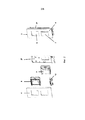
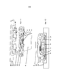
Фиг.1 - отдельные этапы монтажа и демонтажа замыкающей планки,Figure 1 - the individual stages of installation and dismantling of the locking strip,
Фиг.2 - модульное устройство вставного приборного блока,Figure 2 - modular device plug-in instrument unit,
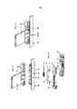
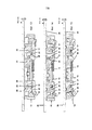
Фиг.3 - запирающий модуль и замыкающая планка, включая запирающий элемент в демонтированном положении,Figure 3 - locking module and locking strip, including the locking element in the dismantled position,
Фиг.4 - запирающий модуль и замыкающая планка в смонтированном положении,Figure 4 - locking module and locking strip in the mounted position,
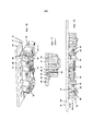
Фиг.5 - отдельные конструктивные элементы запирающего модуля,Figure 5 - individual structural elements of the locking module,
Фиг.6 - первый этап демонтажа замыкающей планки: установка демонтажного инструмента,6 - the first stage of dismantling the locking strip: installation of the dismantling tool,
Фиг.7 - второй этап демонтажа замыкающей планки: сдвиг в поперечном направлении демонтажного инструмента, включая замыкающую планку,7 - the second stage of dismantling the locking strip: a shift in the transverse direction of the dismantling tool, including the locking strip,
Фиг.8 - третий этап демонтажа замыкающей планки: оттягивание замыкающей планки,Fig.8 is the third stage of dismantling the locking strip: pulling the locking strip,
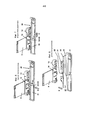
Фиг.9 - вид внизу запирающего модуля и замыкающей планки в демонтированном положении,Fig.9 is a bottom view of the locking module and the locking strip in the dismantled position,
Фиг.10 - вид сверху запирающего модуля и замыкающей планки, включая запирающий элемент в демонтированном положении,Figure 10 is a top view of the locking module and the locking strip, including the locking element in the dismantled position,
Фиг.11 - вид в перспективе снизу запирающего модуля и замыкающей планки, включая запирающий элемент, в демонтированном положении,11 is a perspective view from below of the locking module and the locking strip, including the locking element, in the dismantled position,
Фиг.12 - вид снизу запирающего модуля и замыкающей планки, включая запирающий элемент, в смонтированном положении,12 is a bottom view of the locking module and the locking strip, including the locking element, in the mounted position,
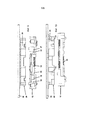
Фиг.13-15 - отдельные этапы при монтаже замыкающей планки, включая запирающий элемент, в поперечном сечении,Fig.13-15 - the individual steps in the installation of the locking plate, including the locking element, in cross section,
Фиг.16 - вид снизу в перспективе запирающего модуля и замыкающей планки, включая запирающий элемент, в смонтированном положении,Fig is a bottom perspective view of the locking module and the locking strip, including the locking element, in the mounted position,
Фиг.17 - фрагмент устройства по фиг.16,Fig - fragment of the device of Fig.16,
Фиг.18 - начало второго этапа демонтажа замыкающей планки в поперечном сечении.Fig - the beginning of the second stage of dismantling the locking strip in cross section.
На фиг.1 представлены отдельные этапы монтажа и демонтажа замыкающей планки. Фиг.1 показывает домофонный пульт 1, в частности дверной домофонный пульт домовой коммуникационной системы, в семи различных изображениях:Figure 1 presents the individual stages of installation and dismantling of the locking strip. Figure 1 shows the
- на первом изображении слева показан вставной приборный блок 3, оборудованный в скрытой розетке 29, главная фронтальная панель 4 в нижнем концевом участке скрытой розетки 29 оставляет свободным отверстие 8 для приема замыкающей планки. При настенном выполнении домофонного пульта 1 нижняя часть корпуса, расположенная на поверхности, используется вместо скрытой розетки 29,- the first image on the left shows the plug-in
- на втором изображении слева показана стрелка A, которая обозначает направление монтажа для замыкающей планки 20 перпендикулярно главной фронтальной панели 4 при установке на выемку 8 домофонного пульта 1,- the arrow A is shown in the second image on the left, which indicates the installation direction for the
- на третьем изображении слева показан домофонный пульт 1 в комплекте, причем между главной фронтальной панелью 4 и запирающей фронтальной панелью замыкающей планки 20 определенным образом выполнен зазор 5,- in the third image on the left shows the
- на четвертом и пятом изображении слева показан первый этап демонтажа замыкающей планки 20, установку демонтажного инструмента 31 на зазор 5, причем стрелка B обозначает направление движения демонтажного инструмента 31 перпендикулярно главной фронтальной панели 4,- in the fourth and fifth image on the left shows the first stage of dismantling the
- на шестом изображении слева показан второй этап демонтажа замыкающей планки 20, сдвиг в поперечном направлении демонтажного инструмента 31, включая замыкающую планку 20, причем стрелка C обозначает направление движения демонтажного инструмента 31 параллельно главной фронтальной панели 4 и вдоль зазора 5,- the sixth image on the left shows the second stage of dismantling the
- на седьмом изображении слева показан третий этап демонтажа замыкающей планки 20, отвод демонтажного инструмента 31 и высвободившейся замыкающей планки 20, причем стрелка D обозначает направление движения демонтажного инструмента 31 и замыкающей планки 20 перпендикулярно от главной фронтальной панели 4.- the seventh image on the left shows the third stage of dismantling the
На фиг.2 показано модульное устройство вставного приборного блока. Предварительно смонтированный вставной приборный блок 3 установлен со своими конструктивными компонентами. При этом можно хорошо рассмотреть модульное устройство со вставным приборным блоком 3, с главной фронтальной панелью 4, монтажной панелью 27, аудиомодулем 6 (с микрофоном, динамиком и усилителем), модулем 7 клавиатуры (со звонковыми клавишами и перечислением имен) и запирающим модулем 12. Фиксирование различных модулей 6, 7, 12 на монтажной панели 27 осуществляется предпочтительно с помощью винтовых соединений.Figure 2 shows a modular device plug-in instrument unit. The pre-mounted plug-in
На фиг.3 представлены запирающий модуль и замыкающая планка, включая запирающий элемент, в демонтированном положении. При этом носитель 9 надписи, который несет на себе (заменяемые) надписи к перечислениям имен модуля 7 клавиатуры, вставлен в запирающий модуль 12 (и, само собой разумеется, также в непоказанный модуль 7 клавиатуры). Замыкающая планка 20 имеет блокирующую рейку с пазом 22 на торцевой стороне своей запирающей фронтальной панели 26, обращенной к главной фронтальной панели 4. При смонтированной замыкающей планке и вставленном носителе 9 надписи выступ 10 носителя 9 надписи входит в этот паз 22, так что без других мероприятий невозможно боковое смещение замыкающей планки 20 относительно запирающего модуля 12.Figure 3 presents the locking module and the locking plate, including the locking element, in the dismantled position. In this case, the
На фиг.4 показаны запирающий модуль и замыкающая планка в смонтированном положении, причем, в частности, особенно хорошо можно распознать вхождение выступа 10 носителя 9 надписи (вдвинутых в запирающий модуль 12 и непоказанный модуль 7 клавиатуры) в паз 22 блокирующей рейки запирающей фронтальной панели 26 замыкающей планки 20.Figure 4 shows the locking module and the locking strip in the mounted position, and, in particular, it is particularly well to recognize the occurrence of the
На фиг.5 показаны отдельные детали запирающего модуля. В главном корпусе запирающего модуля 12 подвижно расположен шибер 14. Этот шибер 14, выполненный в U-образной форме, имеет базовую полку 15 шибера с боковыми полками 16,17 шибера, примыкающими к ней с обеих сторон. Пружина 13 прижимает шибер 14 в стабильное исходное положение или положение покоя.Figure 5 shows the individual parts of the locking module. In the main case of the
На фиг.6 показан первый этап демонтажа замыкающей планки с домофонного пульта, установка демонтажного инструмента, см. к этому также фиг.1 (четвертое и пятое изображение слева). Демонтажный инструмент 31 устанавливается на зазор 5 между главной фронтальной панелью 4 и запирающей фронтальной панелью 26 замыкающей планки 20, причем стрелка B обозначает направление движения демонтажного инструмента 31 перпендикулярно главной фронтальной панели 4. Демонтажный инструмент 31 имеет цапфу 32, которая через паз 22 входит в блокирующую рейку запирающей фронтальной панели 26 замыкающей планки 20 и таким образом прижимается к выступу 10 носителя 9 надписи, так что выступ 10 выдавливается из паза 22. Благодаря этому расцепляется блокирование поперечного смещения между запирающим модулем 12 и замыкающей планкой 20.Figure 6 shows the first stage of dismantling the locking strip from the intercom, installing the dismantling tool, see also figure 1 (fourth and fifth image on the left). The
На фиг.7 показан второй этап демонтажа замыкающей планки с домофонного пульта, смещение демонтажного инструмента в поперечном направлении, см. к этому также фиг.1 (шестое изображение слева): демонтажный инструмент 31 сдвигается поперек параллельно главной фронтальной панели 4 и вдоль зазора 5, причем стрелка C показывает это направление движения демонтажного инструмента 31. Так как цапфа 32 во время этого движения, как и прежде, находится в зацеплении с пазом 22 в блокирующей рейке запирающей фронтальной панели 26 замыкающей планки 20, то замыкающая планка 20 сдвигается в поперечном направлении одинаково с демонтажным инструментом 31 относительно запирающего модуля 12 (включая вдвинутого носителя 9 надписи).Figure 7 shows the second stage of dismantling the locking strip from the intercom, displacement of the dismantling tool in the transverse direction, see also Fig. 1 (sixth image on the left): the dismantling
На фиг.8 показан третий этап демонтажа замыкающей планки с домофонного пульта, оттягивание замыкающей планки, см. также фиг.1 (седьмое изображение слева): как демонтажный инструмент 31, так и высвободившаяся замыкающая планка 20 отводятся, причем стрелка D обозначает направление движения демонтажного инструмента 31 и замыкающей планки 20 перпендикулярно от главной фронтальной панели 4 и от запирающего модуля 12.On Fig shows the third stage of dismantling the locking strip from the intercom, pulling the locking strip, see also Fig. 1 (seventh image on the left): both the
На фиг. 9 показан вид снизу запирающего модуля и замыкающей планки в демонтированном положении. Можно распознать базовую полку 15 шибера, а также обе боковые полки 16, 17 шибера запирающего модуля 12, причем шибер 14 с помощью пружины 13 отжимается в исходное положение или положение покоя. Далее показаны два вводных скоса 18 запирающего модуля 12, которые образованы в дополнение к фиксирующим крючкам 23 замыкающей планки 20, причем для образа функционирования монтажа замыкающей планки 20 на запирающем модуле 12 ссылаемся на последующие фиг.13-15. Замыкающая планка 20 состоит, по существу, из запирающего элемента 21 и запирающей фронтальной панели 26, закрепленной на нем.In FIG. 9 shows a bottom view of the locking module and the locking strip in the dismantled position. You can recognize the
На фиг.10 изображен вид сверху запирающего модуля и замыкающей планки в демонтированном положении, причем, в частности, интерес представляют оба фиксирующих крючка 23 замыкающей планки 20, уже упомянутые в связи с фиг.9. В запирающем модуле 12 можно распознать пружину 13, оттягивающую шибер назад.Figure 10 shows a top view of the locking module and the locking strip in the disassembled position, and, in particular, both the locking hooks 23 of the locking
На фиг.11 представлен вид снизу в перспективе запирающего модуля и замыкающей планки в демонтированном положении. В запирающий модуль 12 (и непоказанный модуль 7 клавиатуры) вставлен носитель 9 надписи. Можно хорошо распознать пружину 13, оттягивающую назад шибер 14 с его обеими боковыми полками 16, 17 шибера в исходное положение или положение покоя, и вводные скосы 18. Далее показаны запирающий элемент 21 и запирающая фронтальная панель 26 замыкающей планки 20.11 is a bottom perspective view of a locking module and a locking bar in a dismantled position. An
На фиг.12 показан вид снизу запирающего модуля и замыкающей планки в смонтированном положении. Можно рассмотреть шибер 14 с базовой полкой 15 шибера, обеими боковыми полками 16,17 шибера и пружину 13 запирающего модуля 12, замыкающую планку 20 с запирающей фронтальной панелью 26, а также вдвинутый носитель 9 надписи.On Fig shows a bottom view of the locking module and the locking plate in the mounted position. You can consider the
На фиг.13-15 представлены отдельные этапы монтажа замыкающей планки в поперечном сечении, причем стрелка A снова обозначает направление монтажа для замыкающей планки 20 перпендикулярно главной фронтальной панели 4 и запирающему модулю 12 при установке на домофонный пульт 1.On Fig-15 presents the individual steps of mounting the closing strip in cross section, and the arrow A again indicates the mounting direction for the locking
- Фиг.13 показывает первую фазу процесса монтажа, при которой фиксирующие крючки 23 запирающего элемента 21 замыкающей планки 20 скользят вдоль вводных скосов 18 с фиксирующими кромками запирающего модуля 12. Боковые полки 16, 17 шибера 14 попадают на вводную воронку 24 запирающего модуля 12.- Fig.13 shows the first phase of the installation process, in which the locking hooks 23 of the locking
- Фиг.14 показывает вторую фазу процесса монтажа с продолжающимся скольжением фиксирующих крючков 23 вдоль вводных скосов 18 и боковых полок 16, 17 шибера вдоль вводной воронки 24, причем боковые полки 16, 17 против усилия пружины 13, находящейся в зацеплении с базовой полкой 15 шибера, сдвигаются по бокам в так называемое положение высвобождения.- Fig. 14 shows a second phase of the mounting process with continued sliding of the locking hooks 23 along the inlet bevels 18 and the
- фиг.15 показывает завершающую фазу процесса монтажа, при которой фиксирующие крючки 23 входят в зацепление через фиксирующие кромки вводных скосов 18, так что без других мероприятий больше невозможен демонтаж замыкающей планки 20 с запирающего модуля. После того как задние зацепления (фиксирующие крючки входят в зацепление через фиксирующие кромки вводных скосов 18) зафиксированы, шибер 14, обусловленный усилием возврата пружины 13, снова идет в свое исходное положение и удерживает замыкающую планку 20 в этом положении, которое теперь соответствует положению блокирования. Дополнительно осуществляется защита от разблокировки с помощью носителя 9 надписей, выступы 10 которого входят в паз 22 в блокирующей рейке запирающей фронтальной панели 26 замыкающей планки 20, как уже было показано в фиг.4.- Fig. 15 shows the final phase of the installation process, in which the locking hooks 23 engage through the locking edges of the input bevels 18, so that without other measures it is no longer possible to dismantle the locking
На фиг.16 представлен вид снизу в перспективе запирающего модуля и замыкающей планки в смонтированном положении. Главная фронтальная панель 4 и запирающая фронтальная панель 26 лежат рядом друг с другом плоско (в единственной плоскости или поверхности) с образованием зазора 5. Можно распознать, что боковые рычаги 19 запирающего модуля 12 входят с зацеплением в карманы 25 запирающего элемента 21 замыкающей планки 20 (см. к этому также деталь T), благодаря чему замыкающая планка 20 притягивается к запирающему модулю 12.On Fig presents a bottom view in perspective of the locking module and the locking strip in the mounted position. The main
На фиг.17 изображена детализированная часть T к построению по фиг.16, в которой можно видеть:On Fig shows a detailed part T to the construction of Fig.16, in which you can see:
- с одной стороны, плоское расположение главной фронтальной панели 4 и запирающей фронтальной панели 26 рядом друг с другом с образованием зазора 5 и- on the one hand, a flat arrangement of the main
- с другой стороны, вхождение с зацеплением бокового рычага 19 запирающего модуля 12, связанного с главной фронтальной панелью 4, в карман 25 запирающего элемента 21 замыкающей планки 20.- on the other hand, the engagement of the
На фиг.18 показано начало второго этапа демонтажа замыкающей планки в поперечном сечении: исходным сценарием является вхождение друг в друга запирающего модуля 12 и запирающего элемента 21 замыкающей планки 20 непосредственно перед поперечным сдвигом демонтажного инструмента, включая замыкающую планку. Можно просто распознать, что при относительном смещении замыкающей планки 20 вправо (параллельно главной фронтальной панели 4 и вдоль зазора 5 - см. направление движения, обозначенное стрелкой C) задние зацепления (фиксирующий крючок 23 входит в зацепление через фиксирующие кромки вводных скосов 18) расцепляются. Одновременно благодаря этому поперечному сдвигу шибер 14 отклоняется из своего положения блокирования (исходное положение или положение покоя) в положение высвобождения, при котором в следующем, третьем, этапе демонтажа замыкающей планки возможен отвод замыкающей планки 20 перпендикулярно от главной фронтальной панели 4 - см. стрелку D на фиг.1, которая показывает направление движения демонтажного инструмента 31 и замыкающей планки 20 после осуществленного демонтажа.On Fig shows the beginning of the second stage of dismantling the locking strip in cross section: the initial scenario is the entry into each other of the
Если выемка 8 в домофонном пульте 1 не прикрыта замыкающей планкой 20, становятся возможными следующие дальнейшие мероприятия:If the
- вставной приборный блок 3 с главной фронтальной панелью 4 в своем нижнем конечном участке может отводиться вперед от скрытой розетки 29 (или наружной нижней части корпуса) на определенный и ограниченный участок пути, благодаря чему простым образом становится возможным отвести носитель 9 надписи из модуля 7 клавиатуры и запирающего модуля 12 или вновь записанный носитель 9 надписи снова вставить в модуль 7 клавиатуры и запирающий модуль 12.- the plug-in
- вставной приборный блок 3 может поворачиваться на угол приблизительно 90° в положение обслуживания (ось вращения образуется нижним участком вставного приборного блока 3, в котором имеется простой доступ к задней стороне вставного приборного блока 3 и, в частности, к его модулю, чтобы таким образом можно было предпринять, например, настройки. Также в этом положении обслуживания простым образом возможна прокладка проводов (соединение с присоединительными проводами).- the plug-in
- вставной приборный блок 3 может полностью демонтироваться, например, при дефекте и требуемой затем замене всего вставного приборного блока.- the plug-in
ПЕРЕЧЕНЬ ССЫЛОЧНЫХ ОБОЗНАЧЕНИЙLIST OF REFERENCE NUMBERS
1 домофонный пульт, в частности дверной домофонный пульт домовой коммуникационной системы1 intercom, in particular a door intercom for a home communications system
2 -2 -
3 вставной приборный блок, предварительно смонтированный3 plug-in instrument unit pre-mounted
4 главная фронтальная панель вставного приборного блока 34 main front panel of the plug-in
5 зазор между главной фронтальной панелью 4 и запирающей фронтальной панелью 26 замыкающей планки 205 the gap between the main
6 аудиомодуль с микрофоном, динамиком, усилителем,6 audio module with microphone, speaker, amplifier,
7 модуль клавиатуры со звонковыми кнопками, перечислениями имен7 keyboard module with call buttons, name transfers
8 выемка (для приема замыкающей планки)8 notch (for receiving the locking strip)
9 носитель надписи9 lettering carrier
10 выступ в носителе 9 надписи10 protrusion in the
11 -eleven -
12 запирающий модуль12 locking module
13 пружина13 spring
14 шибер14 gate
15 базовая полка шибера15 slide gate base
16 боковая полка шибера16 side gate shelf
17 боковая полка шибера17 side gate shelf
18 вводные скосы с фиксирующей кромкой для фиксирующих крючков 2318 inlet chamfers with locking edge for locking
19 боковые рычаги19 side levers
20 замыкающая планка20 locking strip
21 запирающий элемент замыкающей планки 2021 locking element of the locking
22 паз блокирующей рейки на торцевой стороне запирающей фронтальной панели 26 замыкающей планки 20, обращенной к главной фронтальной панели 422 groove of the locking rail on the front side of the locking
23 фиксирующие крючки запирающего элемента 21 замыкающей планки 2023 locking hooks of the locking
24 вводная воронка для боковых полок 16,17 шибера24 opening funnel for side shelves 16.17 gates
25 карманы25 pockets
26 запирающая фронтальная панель замыкающей планки 2026 locking front panel of the locking
27 монтажная плита вставного приборного блока 327 mounting plate of plug-in
28 -28 -
29 скрытая розетка или наружная нижняя часть корпуса29 concealed receptacle or outer lower case
30 -thirty -
31 демонтажный инструмент31 stripping tools
32 цапфа демонтажного инструмента32 axle of the dismantling tool
Claims (4)
- причем домофонный пульт имеет фронтальную панель, разделенную на главную фронтальную панель (4) и запирающую фронтальную панель (26), и между главной фронтальной панелью (4) и запирающей фронтальной панелью (26) образован зазор (5),
- причем главная фронтальная панель (4) жестко связана с вставным приборным блоком (3) и запирающим модулем (12),
- причем запирающая фронтальная панель (26) жестко связана с замыкающей планкой (20), имеющей запирающий элемент (21),
- причем для крепления с возможностью разъема замыкающей планки (20) на домофонном пульте (1) в зацеплении находится заднее крючковое зацепление, при котором фиксирующие крючки (23) запирающего элемента (21) замыкающей планки (20) производят захват через кромки вводных скосов (18) запирающего модуля (12), и
- причем для демонтажа замыкающей планки (20) с домофонного пульта (1) в зазор (5) входит демонтажный инструмент (31), которым замыкающая планка (20) может перемещаться вдоль зазора (5) в поперечном направлении таким образом, что заднее крючковое зацепление снимается.1. The locking device intercom (1), in particular the door intercom remote home communication system,
- moreover, the intercom panel has a front panel divided into a main front panel (4) and a locking front panel (26), and a gap (5) is formed between the main front panel (4) and the locking front panel (26),
- moreover, the main front panel (4) is rigidly connected with the plug-in instrument unit (3) and the locking module (12),
- moreover, the locking front panel (26) is rigidly connected with the locking strip (20) having a locking element (21),
- moreover, for fastening with the possibility of a connector of the locking strip (20) on the intercom panel (1), the rear hook meshing is engaged, in which the locking hooks (23) of the locking element (21) of the locking strip (20) capture through the edges of the entry bevels (18) ) locking module (12), and
- moreover, to dismantle the locking strip (20) from the intercom panel (1), a gap (5) includes a dismantling tool (31), with which the locking strip (20) can be moved along the gap (5) in the transverse direction so that the rear hook engagement removed.
Applications Claiming Priority (2)
| Application Number | Priority Date | Filing Date | Title |
|---|---|---|---|
| DE102011108926.1A DE102011108926B4 (en) | 2011-07-27 | 2011-07-27 | Locking system of a station, in particular a door station, of a home communication system |
| DE102011108926.1 | 2011-07-27 |
Publications (2)
| Publication Number | Publication Date |
|---|---|
| RU2012132214A RU2012132214A (en) | 2014-02-10 |
| RU2597005C2 true RU2597005C2 (en) | 2016-09-10 |
Family
ID=46704424
Family Applications (1)
| Application Number | Title | Priority Date | Filing Date |
|---|---|---|---|
| RU2012132214/07A RU2597005C2 (en) | 2011-07-27 | 2012-07-26 | Device for blocking a phone panel, in particular, door phone panel of the home communication system |
Country Status (4)
| Country | Link |
|---|---|
| EP (1) | EP2551976B1 (en) |
| CN (1) | CN102904985B (en) |
| DE (1) | DE102011108926B4 (en) |
| RU (1) | RU2597005C2 (en) |
Families Citing this family (4)
| Publication number | Priority date | Publication date | Assignee | Title |
|---|---|---|---|---|
| DE102013105893B3 (en) * | 2013-06-07 | 2014-06-26 | Berker Gmbh & Co. Kg | Electrical / electronic installation device |
| DE102013105894B4 (en) | 2013-06-07 | 2018-03-29 | Berker Gmbh & Co. Kg | Electrical / electronic installation device |
| DE102014220307B3 (en) * | 2014-10-07 | 2016-01-07 | Berker Gmbh & Co. Kg | Fastening device for fixing a carrier arrangement of a door communication device in a mounting housing |
| IT201900011856A1 (en) * | 2019-07-16 | 2021-01-16 | Comelit Group S P A | EXTERNAL STATION FOR DOOR PHONE AND / OR VIDEO DOOR PHONE SYSTEM |
Citations (5)
| Publication number | Priority date | Publication date | Assignee | Title |
|---|---|---|---|---|
| RU2071538C1 (en) * | 1993-12-29 | 1997-01-10 | Товарищество с ограниченной ответственностью Научно-производственное предприятие "Вика" | Intercom and locking device |
| DE19642517A1 (en) * | 1996-10-15 | 1998-04-16 | Siedle & Soehne S | Housing connection unit for electrical apparatus |
| WO2008081321A1 (en) * | 2006-12-28 | 2008-07-10 | Bticino S.P.A. | Support panel for video door entry stations with concealed fixing |
| DE202008012876U1 (en) * | 2008-09-27 | 2008-12-04 | Ulrich Lippert Gmbh & Co Kg | door station |
| CN201756851U (en) * | 2010-07-12 | 2011-03-09 | 王亚运 | Lock-out control mechanism and linkage door lock provided with same |
Family Cites Families (4)
| Publication number | Priority date | Publication date | Assignee | Title |
|---|---|---|---|---|
| DE10340759B3 (en) * | 2003-09-02 | 2005-05-04 | Ritto Gmbh & Co. Kg | Door station for a door intercom |
| DE102004016539B4 (en) | 2004-03-31 | 2006-04-13 | Gira Giersiepen Gmbh & Co. Kg | Electrical wiring device, e.g. for a flat/house or door communications facility, has a main part for a surface-type mounting on a wall surface |
| DE202006005366U1 (en) | 2006-04-04 | 2006-07-20 | Gira Giersiepen Gmbh & Co. Kg | Intercom station for a house communication facility has a wall outlet-type mounting case and an insert with a front cover plate for inserting in the case so as to be removable |
| SE532298C2 (en) * | 2008-04-16 | 2009-12-08 | Jokab Safety Ab | Locking |
-
2011
- 2011-07-27 DE DE102011108926.1A patent/DE102011108926B4/en active Active
- 2011-09-23 CN CN201110296403.1A patent/CN102904985B/en active Active
-
2012
- 2012-06-13 EP EP12004469.8A patent/EP2551976B1/en active Active
- 2012-07-26 RU RU2012132214/07A patent/RU2597005C2/en active
Patent Citations (5)
| Publication number | Priority date | Publication date | Assignee | Title |
|---|---|---|---|---|
| RU2071538C1 (en) * | 1993-12-29 | 1997-01-10 | Товарищество с ограниченной ответственностью Научно-производственное предприятие "Вика" | Intercom and locking device |
| DE19642517A1 (en) * | 1996-10-15 | 1998-04-16 | Siedle & Soehne S | Housing connection unit for electrical apparatus |
| WO2008081321A1 (en) * | 2006-12-28 | 2008-07-10 | Bticino S.P.A. | Support panel for video door entry stations with concealed fixing |
| DE202008012876U1 (en) * | 2008-09-27 | 2008-12-04 | Ulrich Lippert Gmbh & Co Kg | door station |
| CN201756851U (en) * | 2010-07-12 | 2011-03-09 | 王亚运 | Lock-out control mechanism and linkage door lock provided with same |
Also Published As
| Publication number | Publication date |
|---|---|
| EP2551976A2 (en) | 2013-01-30 |
| EP2551976B1 (en) | 2019-09-11 |
| CN102904985A (en) | 2013-01-30 |
| RU2012132214A (en) | 2014-02-10 |
| DE102011108926A1 (en) | 2013-01-31 |
| DE102011108926B4 (en) | 2022-02-17 |
| CN102904985B (en) | 2017-03-01 |
| EP2551976A3 (en) | 2017-05-31 |
Similar Documents
| Publication | Publication Date | Title |
|---|---|---|
| RU2597005C2 (en) | Device for blocking a phone panel, in particular, door phone panel of the home communication system | |
| US20200035058A1 (en) | Fare box | |
| JP2015122376A (en) | Electronic apparatus, rail structure, and rack | |
| JP3986869B2 (en) | Electronics | |
| US8281951B2 (en) | Electrical component enclosure | |
| CN105516556A (en) | Camera shooting assembly and electronic device | |
| US20090195994A1 (en) | Access self-service terminal | |
| CN101730430B (en) | Modular electrical apparatus comprising coupling device for connection with further modular electrical apparatus | |
| RU2595605C2 (en) | Mounting system of a station, in particular a door station of a house communication system | |
| CN102215656A (en) | Attachment/detachment mechanism for electronics unit, electronics unit, power-supply unit, and electronics apparatus | |
| WO2012045696A3 (en) | Locking apparatus for inserts for electrical switchgear cabinets | |
| JP2009174664A (en) | Lock mechanism | |
| EP2098047B9 (en) | Support panel for video door entry stations with concealed fixing | |
| CN211627988U (en) | Projector | |
| US9995068B2 (en) | Casing device and electronic equipment | |
| JP5835424B2 (en) | Game machine | |
| JP4136605B2 (en) | Bill recognition device | |
| CN210168363U (en) | Server slide rail locking structure and slide rail using same | |
| CN209786531U (en) | Back-loading replaceable household electric box | |
| JP4966148B2 (en) | Information device | |
| GB2080383A (en) | Vandal-resistant Control Box | |
| CN110087427A (en) | Server slide rail locking structure and the sliding rail for using the structure | |
| CN1159819C (en) | Safety hanging locking device for draw circuit breaker | |
| CN102404017B (en) | Portable electronic device | |
| CN213462005U (en) | Law enforcement appearance assembly structure and law enforcement record appearance |
Legal Events
| Date | Code | Title | Description |
|---|---|---|---|
| PC41 | Official registration of the transfer of exclusive right |
Effective date: 20191210 |