RU2594271C1 - Aircraft - Google Patents
Aircraft Download PDFInfo
- Publication number
- RU2594271C1 RU2594271C1 RU2015123768/11A RU2015123768A RU2594271C1 RU 2594271 C1 RU2594271 C1 RU 2594271C1 RU 2015123768/11 A RU2015123768/11 A RU 2015123768/11A RU 2015123768 A RU2015123768 A RU 2015123768A RU 2594271 C1 RU2594271 C1 RU 2594271C1
- Authority
- RU
- Russia
- Prior art keywords
- shock absorber
- housing
- piston
- rigidly connected
- cylinder
- Prior art date
Links
Images
Landscapes
- Output Control And Ontrol Of Special Type Engine (AREA)
Abstract
Description
Изобретение относится к космической технике и может быть использовано в полетах как в открытом космосе, так и в атмосфере.The invention relates to space technology and can be used in flights both in open space and in the atmosphere.
Известен летательный аппарат, изложенный в материалах патента RU 2134218 С1 (Часовской А.А.), 10.08.1999. В нем обеспечивается надежность за счет применения для амортизации надежных и доступных технических средств.Known aircraft, set forth in the materials of patent RU 2134218 C1 (Chasovskoy A.A.), 08/10/1999. It provides reliability through the use for depreciation of reliable and affordable technical means.
Принцип его работы заключается в следующем.The principle of its work is as follows.
Поршень движется внутри цилиндра с помощью реактивного двигателя. Цилиндр жестко связан с корпусом. Начальный момент движения может осуществляться с помощью реактивных двигателей, жестко связанных с корпусом, и реактивного двигателя поршня. В амортизатор осуществляется подача дозированного количества топлива с блока управления амортизатором. По достижении определенной высоты и скорости в этом амортизаторе происходит по команде с блока управления воспламенение газов. После амортизации газы выходят с помощью выхлопных труб, а корпус и поршень отталкиваются в противоположные стороны. Далее при сближении поршня с амортизатором снова осуществляется воспламенение газов.The piston moves inside the cylinder using a jet engine. The cylinder is rigidly connected to the housing. The initial moment of movement can be carried out using jet engines rigidly connected to the housing, and a jet piston engine. A dosed quantity of fuel is supplied to the shock absorber from the shock absorber control unit. Upon reaching a certain height and speed in this shock absorber, ignition of gases occurs on command from the control unit. After depreciation, the gases exit through the exhaust pipes, and the body and piston are repelled in opposite directions. Further, when the piston approaches the shock absorber, the gases are again ignited.
Однако для увеличения скорости необходимо увеличить количество топливных компонентов в виде окислителя.However, to increase the speed it is necessary to increase the amount of fuel components in the form of an oxidizing agent.
Известен летательный аппарат, изложенный в материалах патента №2438938, БЮЛ 1 от 10.01.2012. В нем в отличие от вышеупомянутого вводится выхлопное сопло впереди амортизатора, а также изогнутая вниз выхлопная труба, размещенная впереди сопла и выходящая после изгиба из корпуса позади него. Кроме того, в состав устройства входят два изогнутые в конце стержня, жестко связанные с поршнем и размещенные позади него. Они имеют возможность жесткой связи с двумя амортизационными предохранительными упорами для предотвращения столкновения поршня с корпусом. Однако для увеличения скорости аппарата при полете в атмосфере, необходимо увеличить количество топливных компонентов в виде окислителя.Known aircraft described in the materials of the patent No. 2438938, BULE 1 from 01/10/2012. In it, in contrast to the aforementioned, an exhaust nozzle in front of the shock absorber is introduced, as well as an exhaust pipe bent downward, located in front of the nozzle and emerging after bending from the body behind it. In addition, the device includes two bent at the end of the rod, rigidly connected with the piston and placed behind it. They have the ability to tightly couple with two shock-absorbing safety stops to prevent the piston from colliding with the housing. However, to increase the speed of the vehicle during flight in the atmosphere, it is necessary to increase the amount of fuel components in the form of an oxidizing agent.
С помощью предложенного устройства увеличивается скорость в атмосфере без увеличения количества топливных компонентов в виде окислителя.Using the proposed device increases the speed in the atmosphere without increasing the number of fuel components in the form of an oxidizing agent.
Достигается это введением устройства забора воздуха на стыке передней части корпуса и использованием блока управления амортизатором с возможностью смешения воздушной струи с окислителем, имеющим гидравлический вход, связанный с гидравлическим выходом устройства забора воздуха.This is achieved by introducing an air intake device at the junction of the front of the housing and using a shock absorber control unit with the possibility of mixing the air stream with an oxidizing agent having a hydraulic inlet connected to the hydraulic outlet of the air intake device.
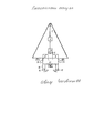
На фиг. 1 и в тексте приняты следующие обозначения:In FIG. 1 and the following notation is used in the text:
1 - устройство забора воздуха1 - air intake device
2 - корпус2 - case
3 - блок управления амортизатором с возможностью смешения воздушной струи с окислителем3 - shock absorber control unit with the possibility of mixing the air stream with an oxidizing agent
4 - изогнутая вниз выхлопная труба4 - bent down exhaust pipe
5 - выхлопное сопло5 - exhaust nozzle
6 - амортизатор6 - shock absorber
7, 8 - реактивные двигатели7, 8 - jet engines
9, 10 - выхлопные трубы9, 10 - exhaust pipes
11 - поршень11 - piston
12 - реактивный двигатель12 - jet engine
13 - цилиндр13 - cylinder
14, 15 - изогнутые в конце стержни14, 15 - rods bent at the end
16, 17 - амортизационные предохранительные упоры.16, 17 - depreciation safety stops.
Корпус 2 аппарата имеет жесткую связь с блоком управления амортизатором, с возможностью смешения воздушной струи с окислителем 3, имеющим выход, гидравлически связанный с входом амортизатора 6. Последний имеет жесткую связь с выхлопным соплом 5, жестко связанным с изогнутой вниз выхлопной трубой 4. Эта труба жестко связана с корпусом 1, имеющим жесткую связь с реактивными двигателями 7, 8 и цилиндром 13. Цилиндр 13 жестко связан с выхлопными трубами 9, 10 и амортизационными предохранительными упорами 16, 17. Внутри имеется поршень 11, жестко связанный с реактивным двигателем 12 и изогнутыми в конце стержнями 14, 15. Корпус жестко связан с устройством забора воздуха 1.The
Работа устройства осуществляется следующим образомThe operation of the device is as follows
Поршень 11 движется внутри цилиндра 13 с помощью реактивного двигателя 12, жестко связанного с поршнем. Реактивный двигатель может быть твердотопливным. Цилиндр жестко связан с корпусом 2. В начальный период времени движение осуществляется с помощью реактивных двигателей, жестко связанных корпусом, а также с помощью реактивного двигателя 12. При этом изогнутые части стержней 14, 15, жестко связанные с поршнем, примыкают к амортизационным предохранительным упорам, и поршень находится в крайнем переднем положении, примыкая к амортизатору 6. В начале движения возможно воспламенение газов в амортизаторе, куда непрерывно поступает топливо с блока управления, и воспламененные газы истекают через выхлопное сопло 5 и изогнутую вниз выхлопную трубу 4, выходящую позади корпуса. После достижения определенной высоты полета прекращается непрерывное воспламенение топлива в амортизаторе и происходит подача его дозированного количества с блока управления амортизатором с возможностью смешения воздушной струи с окислителем 3, благодаря его гидравлической связи с этим амортизатором. После поступления топлива осуществляется воспламенение газов и их импульсное истечение через вышеупомянутое выхлопное сопло и изогнутую выхлопную трубу.The
При этом происходит также отталкивание поршня и корпуса в противоположные стороны. После амортизации газы выходят через выхлопные трубы. Однако в связи с работой реактивного двигателя движение поршня в обратную сторону прекращается и он начинает двигаться навстречу амортизатору. Далее при сближении поршня с амортизатором снова осуществляется воспламенение газов и амортизационный цикл повторяется. При этом за время движения поршня в амортизатор поступила очередная доза топлива.In this case, the piston and the housing are also repelled in opposite directions. After depreciation, the gases exit through the exhaust pipes. However, in connection with the operation of the jet engine, the movement of the piston in the opposite direction stops and it begins to move towards the shock absorber. Further, when the piston approaches the shock absorber, the gases are again ignited and the depreciation cycle is repeated. At the same time, during the movement of the piston, the next dose of fuel entered the shock absorber.
В отличие от главного аналога в предлагаемом устройстве гидравлический вход блока управления 3 связан с гидравлическим выходом устройства забора воздуха 1, размещенного на стыке передней части корпуса 2. Таким образом, увеличивается количество кислородных компонентов, смешивающихся с окислителем, также происходит смешение с керосином. Следовательно, увеличивается тяга и скорость аппарата при полете в атмосфере. Таким образом, обеспечивается увеличение скорости движения в атмосфере. Устройство можно использовать для доставки пассажиров и грузов в удаленные районы.Unlike the main analogue in the proposed device, the hydraulic input of the
Также увеличивается надежность при импульсном истечении воспламененных газов, так как остаточные воспламененные газы выходят через выхлопные трубы после амортизации, а также предотвращается столкновение поршня с корпусом, так как изогнутые части стержней входят в соприкосновение с упорами. Возможен вариант применения, когда подача топлива и воспламенение его произойдет после соприкосновения с упорами. При этом исключается утечка невоспламеняемого топлива через выхлопные трубы. Возможны также частные варианты применения - когда реактивные двигатели, выхлопные трубы и выхлопное сопло и изогнутая труба - не используются. При этом частота амортизационных циклов должна обеспечить полный выхлоп воспламеняемых газов.Reliability also increases during pulsed outflow of ignited gases, since residual ignited gases escape through the exhaust pipes after cushioning, and the piston collides with the housing as the curved parts of the rods come into contact with the stops. A possible application is when the fuel supply and ignition will occur after contact with the stops. This eliminates the leakage of non-flammable fuel through the exhaust pipes. Private applications are also possible - when jet engines, exhaust pipes and an exhaust nozzle and a bent pipe are not used. At the same time, the frequency of depreciation cycles should ensure the complete exhaust of flammable gases.
Переносимость перегрузки людьми улучшается при уменьшении силы отталкиваний. Выход поршня из цилиндра предотвращается благодаря вышеупомянутым упорам. Плавность движения поршня внутри цилиндра обеспечивается благодаря наличию специальных покрытий. Таким образом в предлагаемом устройстве обеспечивается энергосбережение и уменьшается время полета, что обеспечивает экономический эффект. Устройство можно использовать в комбинированных двигателях, в том числе и предложенных в патентах автора, что многократно увеличивает скорость полета и улучшает тактико-технические характеристики летательных средств.Human overload tolerance improves with reduced repulsive power. The piston exit from the cylinder is prevented by the aforementioned stops. The smooth movement of the piston inside the cylinder is ensured by the presence of special coatings. Thus, in the proposed device provides energy saving and reduces flight time, which provides an economic effect. The device can be used in combined engines, including those proposed in the patents of the author, which greatly increases flight speed and improves the tactical and technical characteristics of aircraft.
Claims (1)
Priority Applications (1)
| Application Number | Priority Date | Filing Date | Title |
|---|---|---|---|
| RU2015123768/11A RU2594271C1 (en) | 2015-06-18 | 2015-06-18 | Aircraft |
Applications Claiming Priority (1)
| Application Number | Priority Date | Filing Date | Title |
|---|---|---|---|
| RU2015123768/11A RU2594271C1 (en) | 2015-06-18 | 2015-06-18 | Aircraft |
Publications (1)
| Publication Number | Publication Date |
|---|---|
| RU2594271C1 true RU2594271C1 (en) | 2016-08-10 |
Family
ID=56613068
Family Applications (1)
| Application Number | Title | Priority Date | Filing Date |
|---|---|---|---|
| RU2015123768/11A RU2594271C1 (en) | 2015-06-18 | 2015-06-18 | Aircraft |
Country Status (1)
| Country | Link |
|---|---|
| RU (1) | RU2594271C1 (en) |
Citations (4)
| Publication number | Priority date | Publication date | Assignee | Title |
|---|---|---|---|---|
| US3756024A (en) * | 1962-02-23 | 1973-09-04 | Gen Dynamics Corp | Method and apparatus for coordinating propulsion in a single stage space flight |
| FR2642473A2 (en) * | 1985-04-30 | 1990-08-03 | Canot Albert | Improvements made to flying machines and to their thrusters |
| RU2134218C1 (en) * | 1998-05-15 | 1999-08-10 | Часовской Александр Абрамович | Flying vehicle |
| RU2438938C1 (en) * | 2010-10-28 | 2012-01-10 | Александр Абрамович Часовской | Aircraft |
-
2015
- 2015-06-18 RU RU2015123768/11A patent/RU2594271C1/en active
Patent Citations (4)
| Publication number | Priority date | Publication date | Assignee | Title |
|---|---|---|---|---|
| US3756024A (en) * | 1962-02-23 | 1973-09-04 | Gen Dynamics Corp | Method and apparatus for coordinating propulsion in a single stage space flight |
| FR2642473A2 (en) * | 1985-04-30 | 1990-08-03 | Canot Albert | Improvements made to flying machines and to their thrusters |
| RU2134218C1 (en) * | 1998-05-15 | 1999-08-10 | Часовской Александр Абрамович | Flying vehicle |
| RU2438938C1 (en) * | 2010-10-28 | 2012-01-10 | Александр Абрамович Часовской | Aircraft |
Non-Patent Citations (1)
| Title |
|---|
| Андреев А.В. О взаимодействии относительного и абсолютного движений при реактивном ускорении системы с обменом энергией. Тр.XVII Чтений К.Э.Циолковского. Секц."Пробл. ракетн. и космич. техники".-М.:1983, с.42-48. * |
Similar Documents
| Publication | Publication Date | Title |
|---|---|---|
| Yao et al. | Reinitiation phenomenon in hydrogen-air rotating detonation engine | |
| Bulat et al. | Detonation Jet Engine. Part 2--Construction Features. | |
| Gamble et al. | Improving off-design nozzle performance using fluidic injection | |
| Yungster et al. | Multiple-cycle simulation of a pulse detonation engine ejector | |
| RU2594271C1 (en) | Aircraft | |
| Tran | One dimensional analysis program for scramjet and ramjet flowpaths | |
| RU2438938C1 (en) | Aircraft | |
| Kailasanath | Applications of detonations to propulsion-A review | |
| Wilson et al. | Analysis of a pulsed normal detonation wave engine concept | |
| CN105043772B (en) | Three performance test method of solid rocket ramjet free jet | |
| CN104963788B (en) | Hybrid engine applicable for aviation, spaceflight and navigation | |
| Eidelman et al. | Pulsed detonation engine: Key issues | |
| RU2704639C1 (en) | Aircraft | |
| RU2560224C1 (en) | Airborne vehicle | |
| RU2600259C1 (en) | Aircraft | |
| RU2297953C1 (en) | Flying vehicle | |
| Kailasanath et al. | Computational studies of pulse detonation engines | |
| RU2577742C2 (en) | Aircraft | |
| RU2576851C1 (en) | Aircraft | |
| RU2577750C1 (en) | Aircraft | |
| RU2449931C1 (en) | Spacecraft | |
| RU2616095C1 (en) | Aircraft | |
| RU2403189C1 (en) | Aircraft | |
| RU2378162C1 (en) | Aircraft | |
| RU2329919C1 (en) | Flight vehicle |