RU2593733C1 - Interior panel of aircraft with acoustic materials - Google Patents
Interior panel of aircraft with acoustic materials Download PDFInfo
- Publication number
- RU2593733C1 RU2593733C1 RU2015103863/11A RU2015103863A RU2593733C1 RU 2593733 C1 RU2593733 C1 RU 2593733C1 RU 2015103863/11 A RU2015103863/11 A RU 2015103863/11A RU 2015103863 A RU2015103863 A RU 2015103863A RU 2593733 C1 RU2593733 C1 RU 2593733C1
- Authority
- RU
- Russia
- Prior art keywords
- panel
- aircraft
- fuselage
- wall
- elements
- Prior art date
Links
Images
Classifications
-
- B—PERFORMING OPERATIONS; TRANSPORTING
- B64—AIRCRAFT; AVIATION; COSMONAUTICS
- B64C—AEROPLANES; HELICOPTERS
- B64C1/00—Fuselages; Constructional features common to fuselages, wings, stabilising surfaces or the like
- B64C1/40—Sound or heat insulation, e.g. using insulation blankets
-
- B—PERFORMING OPERATIONS; TRANSPORTING
- B64—AIRCRAFT; AVIATION; COSMONAUTICS
- B64C—AEROPLANES; HELICOPTERS
- B64C1/00—Fuselages; Constructional features common to fuselages, wings, stabilising surfaces or the like
- B64C1/06—Frames; Stringers; Longerons ; Fuselage sections
- B64C1/066—Interior liners
Landscapes
- Engineering & Computer Science (AREA)
- Mechanical Engineering (AREA)
- Aviation & Aerospace Engineering (AREA)
- Soundproofing, Sound Blocking, And Sound Damping (AREA)
Abstract
Description
Перекрестная ссылка на родственные заявкиCross reference to related applications
По данной заявке испрашивается приоритет на основании предварительной заявки на патент США № 61/668614, поданной 6 июля 2012 г., которая включена в настоящий документ путем ссылки в полном объеме.This application claims priority based on provisional patent application US No. 61/668614, filed July 6, 2012, which is incorporated herein by reference in full.
Область техники, к которой относится изобретениеFIELD OF THE INVENTION
Настоящее изобретение относится к интерьерной панели летательного аппарата и, более конкретно, к интерьерной панели летательного аппарата со свойствами ослабления шума.The present invention relates to an aircraft interior panel, and more particularly, to an aircraft interior panel with noise attenuation properties.
Уровень техникиState of the art
Коммерческие летательные аппараты, такие как Airbus A320 или Boeing 737, изготовлены из модульных компонентов, размер, вес и конструкция которых диктуются многими соображениями, в том числе размерами фюзеляжа, соображениями эстетики и безопасности. Многие из этих требований введены законом или нормативным актом. Все компоненты летательного аппарата, такие как верхние багажные полки, сиденья, санузлы, бортовые кухни, системы освещения и т.д., должны функционировать в строго ограниченном пространстве.Commercial aircraft, such as the Airbus A320 or Boeing 737, are made of modular components whose size, weight and design are dictated by many considerations, including fuselage dimensions, aesthetics and safety. Many of these requirements are introduced by law or regulation. All components of the aircraft, such as upper luggage racks, seats, bathrooms, kitchens, lighting systems, etc., must operate in a strictly limited space.
Производители летательных аппаратов постоянно совершенствуют дизайн интерьера летательных аппаратов для достижения большего комфорта и утилитарности для пассажиров и экипажа при введенных на перевозчика ограничениях на стоимость, вес, время простоя на техническое обслуживание и безопасность. Современные интерьерные стеновые панели, используемые в промышленности интерьеров летательных аппаратов, основаны на принципе наращивания, широко используемом в течение многих десятилетий. Композитная сэндвич-панель сегодня является главным элементом в промышленности интерьеров летательных аппаратов. Многие поставщики панелей и акустики ищут новые пути развития композитной сэндвич-панели, включая различные процедуры обработки оболочки панели.Aircraft manufacturers are constantly improving the interior design of aircraft to achieve greater comfort and utility for passengers and crew, with restrictions imposed on the carrier for cost, weight, and downtime for maintenance and safety. Modern interior wall panels used in the aircraft interior industry are based on the building principle that has been widely used for many decades. Composite sandwich panel is today the main element in the aircraft interior industry. Many suppliers of panels and acoustics are looking for new ways to develop a composite sandwich panel, including various panel sheathing procedures.
Раскрытие изобретенияDisclosure of invention
В соответствии с первым аспектом настоящего изобретения предложен узел панели, который включает в себя первую панель, имеющую внутреннюю поверхность и наружную поверхность, и вторую панель, имеющую внутреннюю поверхность и наружную поверхность. Вторая панель включает в себя множество образованных в ней реберных элементов, которые пролегают внутрь. Реберные элементы включают в себя внутреннюю поверхность и наружную поверхность. Между множеством реберных элементов образовано множество панельных участков. Панельные участки включают в себя внутреннюю поверхность и наружную поверхность. Внутренняя поверхность реберных элементов прикреплена к внутренней поверхности первой панели, а внутренняя поверхность панельных участков находится на расстоянии от внутренней поверхности первой панели, чтобы образовать по меньшей мере первую и вторую полости. В предпочтительном варианте осуществления узел панели включает в себя первый элемент акустической обработки, расположенный в первой полости. Первый элемент акустической обработки прикреплен по меньшей мере к одной внутренней поверхности первой панели или внутренней поверхности второй панели. Предпочтительно, что между первым элементом акустической обработки и одной внутренней поверхностью первой панели или внутренней поверхностью второй панели образовано пространство. В предпочтительном варианте осуществления первый элемент акустической обработки образован по меньшей мере первым и вторым слоями. Предпочтительно, что первый элемент акустической обработки прикреплен к внутренней поверхности второй панели, а вторая панель включает в себя множество образованных в ней выступающих участков. В предпочтительном варианте осуществления узел панели включает в себя второй элемент акустической обработки. Первый элемент акустической обработки прикреплен к внутренней поверхности первой панели, а второй элемент акустической обработки прикреплен к внутренней поверхности наружной панели, и между первым и вторым элементами акустической обработки образовано пространство. В одном варианте осуществления вторая полость образует канальное пространство и не включает в себя элемент акустической обработки. В предпочтительном варианте осуществления узел панели включает в себя наружный элемент акустической обработки, прикрепленный по меньшей мере к участку наружной поверхности второй панели, и декоративную панель, прикрепленную к наружной поверхности первого панельного элемента.According to a first aspect of the present invention, there is provided a panel assembly that includes a first panel having an inner surface and an outer surface, and a second panel having an inner surface and an outer surface. The second panel includes a plurality of rib elements formed therein, which lie inward. The rib elements include an inner surface and an outer surface. Between the plurality of rib elements, plural panel portions are formed. Panel sections include an inner surface and an outer surface. The inner surface of the rib elements is attached to the inner surface of the first panel, and the inner surface of the panel sections is at a distance from the inner surface of the first panel to form at least the first and second cavities. In a preferred embodiment, the panel assembly includes a first acoustic treatment element located in the first cavity. The first acoustic treatment element is attached to at least one inner surface of the first panel or the inner surface of the second panel. Preferably, a space is formed between the first acoustic treatment element and one inner surface of the first panel or the inner surface of the second panel. In a preferred embodiment, the first acoustic treatment element is formed by at least the first and second layers. Preferably, the first acoustic treatment element is attached to the inner surface of the second panel, and the second panel includes a plurality of protruding portions formed therein. In a preferred embodiment, the panel assembly includes a second acoustic processing element. The first acoustic treatment element is attached to the inner surface of the first panel, and the second acoustic treatment element is attached to the inner surface of the outer panel, and a space is formed between the first and second acoustic processing elements. In one embodiment, the second cavity forms a channel space and does not include an acoustic treatment element. In a preferred embodiment, the panel assembly includes an external acoustic processing element attached to at least a portion of the external surface of the second panel, and a decorative panel attached to the external surface of the first panel element.
В соответствии с первым аспектом настоящего изобретения предложена стенка фюзеляжа воздушного судна, которая включает в себя множество каркасных элементов и узел панели, который включает в себя первую панель, имеющую внутреннюю поверхность и наружную поверхность, и вторую панель, имеющую внутреннюю поверхность и наружную поверхность. Вторая панель включает в себя множество образованных в ней реберных элементов, которые пролегают внутрь и каждый образует наружную реберную полость. Реберные элементы включают в себя внутреннюю поверхность и наружную поверхность. Между множеством панельных участков образовано множество реберных элементов. Панельные участки включают в себя внутреннюю поверхность и наружную поверхность. Внутренняя поверхность реберных элементов прикреплена к внутренней поверхности первой панели, а внутренние поверхности панельных участков находятся на расстоянии от внутренней поверхности первой панели, чтобы образовать по меньшей мере первую и вторую полости. По меньшей мере некоторые из каркасных элементов вставлены по меньшей мере в некоторые из наружных реберных полостей.According to a first aspect of the present invention, there is provided an aircraft fuselage wall, which includes a plurality of frame members and a panel assembly that includes a first panel having an inner surface and an outer surface, and a second panel having an inner surface and an outer surface. The second panel includes a plurality of rib elements formed therein, which lie inward and each forms an outer rib cavity. The rib elements include an inner surface and an outer surface. Between a plurality of panel portions, a plurality of rib elements are formed. Panel sections include an inner surface and an outer surface. The inner surface of the rib elements is attached to the inner surface of the first panel, and the inner surfaces of the panel sections are located at a distance from the inner surface of the first panel to form at least the first and second cavities. At least some of the frame elements are inserted into at least some of the outer costal cavities.
В примерном варианте осуществления настоящее изобретение не включает в себя обработку мастикой, например, Bondo (тем не менее, в другом варианте осуществления обработка мастикой может быть выполнена). При применении настоящее изобретение может обеспечить снижение передачи шума примерно на 8-10% по сравнению с известным уровнем техники (тем не менее, данный диапазон приведен только в качестве примера и не является ограничением). Кроме того, процесс производства является энергоэффективным, и в нем предпочтительно используют многоразовые и пригодные для переработки материалы. Панели обеспечивают водопоглощение от нуля до небольших величин, легкую отделку поверхности, приблизительно шестьдесят секунд нагрузки под прессом и оберточный декор с соответствием FLAM. Панели могут быть изготовлены из таких материалов, как Ultem и волокнистый композитный материал, термоформованный материал в предпочтительном варианте осуществления. Панели могут иметь большое разнообразие форм со встроенными свойствами акустической обработки.In an exemplary embodiment, the present invention does not include mastic processing, for example, Bondo (however, in another embodiment, mastic processing can be performed). When used, the present invention can provide a noise reduction of about 8-10% compared with the prior art (however, this range is given only as an example and is not a limitation). In addition, the manufacturing process is energy efficient and preferably uses reusable and recyclable materials. The panels provide water absorption from zero to small values, easy surface finish, approximately sixty seconds of load under the press and wrapping decor with FLAM compliance. The panels may be made of materials such as Ultem and a fibrous composite material, a thermoformed material in a preferred embodiment. The panels can have a wide variety of shapes with integrated acoustic processing properties.
В предпочтительном варианте осуществления узел панели включает в себя две (внутреннюю и наружную) панели, скрепленные друг с другом. Внутренняя панель имеет гладкое поперечное сечение, а наружная панель имеет гофрированное поперечное сечение. Наружная панель обеспечивает жесткость узла панели с помощью встроенных опорных ребер. Специалистам в этой области техники понятно, что внутренние и наружные панели могут быть изготовлены из других материалов, например фенольных (например, выполненные способом ускоренного формования “Crush Core” сотовые панели или укладочные ламинаты). Путем пространственного отделения двух панелей друг от друга настоящее изобретение обеспечивает прочную конструкцию, что придает узлу панели прочность. Конструкция «двойная панель - стенка» и «пространство - полость» между ними обеспечивает акустический барьер.In a preferred embodiment, the panel assembly includes two (inner and outer) panels fastened to each other. The inner panel has a smooth cross section, and the outer panel has a corrugated cross section. The outer panel provides rigidity to the panel assembly with integrated support ribs. Those skilled in the art will appreciate that the inner and outer panels can be made of other materials, such as phenolic (for example, honeycomb panels or layered laminates made using the Crush Core accelerated molding process). By spatially separating the two panels from each other, the present invention provides a robust construction that gives the panel assembly strength. The double-panel-wall and space-cavity designs between them provide an acoustic barrier.
В предпочтительном варианте осуществления полость между внутренней и наружной панелями включает в себя элементы акустической обработки, такие как один или несколько слоев одинаковых или разных материалов, которые создают акустический барьер. В предпочтительном варианте осуществления полость включает в себя многослойный элемент обработки. Слои элемента обработки выполнены из материалов, которые имеют различные акустические импедансы. Поэтому при прохождении через них шума на каждом стыке между различными материалами/слоями происходит уменьшение эффективности распространения звука, что ведет к снижению уровня шума. В одном из вариантов осуществления другой элемент акустической обработки может быть расположен снаружи гофрированной наружной панели для дополнительной акустической изоляции.In a preferred embodiment, the cavity between the inner and outer panels includes acoustic processing elements, such as one or more layers of the same or different materials, which create an acoustic barrier. In a preferred embodiment, the cavity includes a multilayer treatment element. The layers of the processing element are made of materials that have different acoustic impedances. Therefore, when noise passes through them at each junction between different materials / layers, the sound propagation efficiency decreases, which leads to a decrease in the noise level. In one embodiment, another acoustic processing element may be located outside the corrugated outer panel for additional acoustic insulation.
Как показано на чертежах, в примерном варианте осуществления настоящее изобретение сочетает в себе декоративную панель и первую конструктивную панель со второй конструктивной панелью, чтобы задать расстояние между ними и способность прикреплять акустические материалы к различным конструктивным поверхностям. Способность обеспечить несколько различных величин плотности материала (в том числе воздушные карманы) в слоях (ключ к шумопоглощению) увеличивается здесь при соблюдении предложенной технологии сборки.As shown in the drawings, in an exemplary embodiment, the present invention combines a decorative panel and a first structural panel with a second structural panel to define a distance between them and the ability to attach acoustic materials to various structural surfaces. The ability to provide several different values of the density of the material (including air pockets) in the layers (the key to noise absorption) is increased here, subject to the proposed assembly technology.
Изобретение вместе с дополнительными признаками и преимуществами можно лучше понять, обратившись к последующему описанию.The invention, together with additional features and advantages, can be better understood by referring to the following description.
Краткое описание чертежейBrief Description of the Drawings
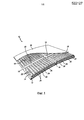
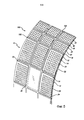
Фиг. 1 - вид в перспективе узла панели в соответствии с вариантом осуществления настоящего изобретения;FIG. 1 is a perspective view of a panel assembly in accordance with an embodiment of the present invention;
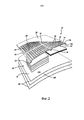
Фиг. 2 - покомпонентный вид в перспективе узла панели по фиг. 1;FIG. 2 is an exploded perspective view of the panel assembly of FIG. one;
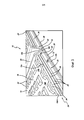
Фиг. 3 - вид в перспективе конца узла панели с фиг.1;FIG. 3 is a perspective view of the end of the panel assembly of FIG. 1;
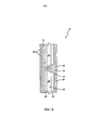
Фиг. 4 - вид в разрезе узла панели с фиг.1;FIG. 4 is a sectional view of the panel assembly of FIG. 1;
Фиг. 5 - вид в перспективе узла панели с фиг.1, встроенной в стенку летательного аппарата; иFIG. 5 is a perspective view of the panel assembly of FIG. 1 embedded in the wall of an aircraft; and
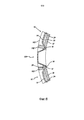
Фиг. 6 - вид в разрезе, взятый по линии 6-6 по фиг.5.FIG. 6 is a sectional view taken along line 6-6 of FIG. 5.
Осуществление изобретенияThe implementation of the invention
Нижеследующее описание и чертежи являются иллюстративными и не должны быть истолкованы как имеющие ограничительный характер. Многочисленные конкретные детали описаны, чтобы обеспечить полное понимание изобретения. Тем не менее, в некоторых случаях хорошо известные или обычные детали не описаны во избежание усложнения описания. Ссылки на тот или иной вариант осуществления в настоящем описании могут быть, но не обязательно являются ссылками на один и тот же вариант осуществления изобретения; и такие ссылки подразумевают по меньшей мере один из вариантов осуществления изобретения.The following description and drawings are illustrative and should not be construed as limiting. Numerous specific details have been described to provide a thorough understanding of the invention. However, in some cases, well-known or ordinary details are not described in order to avoid complicating the description. References to one or another embodiment in the present description may be, but are not necessarily references to the same embodiment of the invention; and such references imply at least one embodiment of the invention.
Ссылка в данном описании на «один вариант осуществления» или «вариант осуществления» означает, что конкретный признак, конструкция или характеристика, описанные в связи с вариантом воплощения, включена по меньшей мере в один вариант осуществления изобретения. Появления фразы «в одном варианте» в различных местах в описании не обязательно относятся к одному и тому же варианту, а также к отдельным или к альтернативным вариантам осуществления, взаимоисключающим с другими вариантами осуществления. Кроме того, описаны различные признаки, которые могут быть изложены теми, а не иными вариантами осуществления. Кроме того, описаны различные требования, которые могут представлять собой требования для тех, а не иных вариантов осуществления.A reference in this description to “one embodiment” or “embodiment” means that a particular feature, structure, or characteristic described in connection with an embodiment is included in at least one embodiment of the invention. Appearances of the phrase “in one embodiment” at various places in the description do not necessarily refer to the same embodiment, as well as to separate or alternative embodiments that are mutually exclusive with other embodiments. In addition, various features are described that may be set forth by those and not other embodiments. In addition, various requirements are described that may constitute requirements for those and not other embodiments.
Термины, используемые в данном описании, как правило, приведены в своих обычных значениях в уровне техники, в контексте описания, и в конкретном контексте, где использован каждый термин. Некоторые термины, которые использованы для описания изобретения, будут рассмотрены ниже или в другом месте в описании, чтобы обеспечить дополнительное руководство для практикующего специалиста в отношении описания изобретения. Для удобства некоторые термины могут быть выделены, например, курсивом и/или кавычками: использование выделения никак не влияет на объем и смысл термина; сфера применения и значение термина являются одинаковыми, в одинаковом контексте, вне зависимости от того, выделен он или нет. Следует иметь в виду, что одинаковый смысл может быть выражен более чем одним способом.The terms used in this description, as a rule, are given in their usual meanings in the prior art, in the context of the description, and in the specific context where each term is used. Some of the terms that are used to describe the invention will be discussed below or elsewhere in the description in order to provide further guidance to a practitioner regarding the description of the invention. For convenience, some terms can be highlighted, for example, in italics and / or quotation marks: using highlighting does not affect the scope and meaning of the term; the scope and meaning of the term are the same, in the same context, regardless of whether it is highlighted or not. It should be borne in mind that the same meaning can be expressed in more than one way.
Соответственно, для любого одного или нескольких обсуждаемых здесь терминов могут быть использованы альтернативный язык и синонимы. Разработанным или обсуждаемым здесь терминам не придается каких-либо особых значений. Для некоторых терминов приведены синонимы. Перечисление одного или нескольких синонимов не исключает использования других синонимов. Использование примеров в любом месте в данном описании, включая примеры любых описанных здесь терминов, является только иллюстративным и не предназначено для дополнительного ограничения объема и смысла описания или любого приведенного в качестве примера термина. Кроме того, изобретение не ограничено различными вариантами осуществления, приведенными в данном описании.Accordingly, for any one or more of the terms discussed herein, an alternative language and synonyms may be used. The terms developed or discussed here are not given any particular meaning. Synonyms are provided for some terms. Enumeration of one or more synonyms does not exclude the use of other synonyms. The use of examples anywhere in this description, including examples of any of the terms described herein, is illustrative only and is not intended to further limit the scope and meaning of the description or any example term given. In addition, the invention is not limited to the various embodiments described herein.
Без намерения дополнительных ограничений объема изобретения ниже приведены примеры инструментов, устройств, способов и связанных с ними результатов в соответствии с вариантами осуществления настоящего изобретения. Следует отметить, что для удобства читателя в примерах могут быть использованы заголовки или подзаголовки, которые ни в коей мере не должны ограничивать объем изобретения. Если не указано иное, все используемые здесь технические и научные термины имеют значение, обычно придаваемое им специалистом в области техники, к которой относится данное изобретение. В случае противоречия приоритет имеет настоящий документ, включая определения.Without the intention of further limiting the scope of the invention, examples of tools, devices, methods, and associated results are provided below in accordance with embodiments of the present invention. It should be noted that for the convenience of the reader, the examples may use headings or subheadings, which should in no way limit the scope of the invention. Unless otherwise indicated, all technical and scientific terms used herein have the meanings commonly given to them by those skilled in the art to which this invention pertains. In the event of a conflict, this document, including definitions, takes precedence.
Следует понимать, что такие термины, как «передний», «задний», «верхний», «нижний», «боковой», «короткий», «длинный», «вверх», «вниз» и «ниже», используемые здесь, приведены только для простоты описания и относятся к ориентации компонентов, как показано на чертежах. Следует понимать, что любая ориентация описанных здесь компонентов находится в пределах объема настоящего изобретения.It should be understood that terms such as “front”, “rear”, “upper”, “lower”, “lateral”, “short”, “long”, “up”, “down” and “lower” are used here are provided for ease of description only and relate to the orientation of the components as shown in the drawings. It should be understood that any orientation of the components described herein is within the scope of the present invention.
Как видим теперь из чертежей, на которых показаны виды, предназначенные для целей иллюстрации настоящего изобретения, а не в ограничительных целях, на фиг.1-6 показан узел 10 панели для использования в стенке 100 транспортного средства, например летательного аппарата. В частности, изобретение предполагается для использования на коммерческом пассажирском летательном аппарате. Тем не менее, это не является ограничением настоящего изобретения, и узлы панели могут быть использованы в других местах.As we now see from the drawings, in which views are shown intended to illustrate the present invention, and not for restrictive purposes, Figs. 1-6 show a
Как показано на фиг.1-4, в предпочтительном варианте осуществления узел 10 панели включает в себя первую панель 12, имеющую внутреннюю поверхность 12а и наружную поверхность 12b, а также вторую панель 14, имеющую внутреннюю поверхность 14а и наружную поверхность 14b. При расположении в летательном аппарате первая панель является внутренней панелью, а вторая панель является наружной панелью. В предпочтительном варианте осуществления вторая панель 14 является гофрированной, чтобы образовать множество реберных элементов 16 и множество панельных участков 18. Следует иметь в виду, что внутренние и наружные поверхности реберных элементов и панельные участки такие же, как и внутренние, и наружные поверхности наружной панели. Тем не менее, для простоты описания, реберные элементы 16 включают в себя внутреннюю поверхность 16а и наружную поверхность 16b, а панельные участки 18 включают в себя внутреннюю поверхность 18а и наружную поверхность 18b.As shown in FIGS. 1-4, in a preferred embodiment, the
Предпочтительно, что вторая панель 14 включает в себя множество образованных в ней реберных элементов 16, которые ориентированы внутрь и каждый из которых образует наружную реберную полость 20. В предпочтительном варианте осуществления внутренняя поверхность 16а реберных элементов 16 прикреплена к внутренней поверхности 12а первой панели 12. Это может быть достигнуто любым способом, известным в данной области техники, таким как склеивание, присоединение, прикрепление, закрепление с помощью крепежа, сварка и т.д. Кроме того, элемент акустической обработки или слой и пр. может быть расположен между внутренней поверхностью 16а реберных элементов 16 и внутренней поверхностью 12а первой панели 12. Это входит в понятие «прикрепления» в рамках настоящего изобретения.Preferably, the
Как показано на фиг.3, внутренняя поверхность каждого панельного участка 18а находится на расстоянии от внутренней поверхности первой панели 12а, чтобы образовать множество полостей 22. В предпочтительном варианте осуществления по меньшей мере участок полостей 22 включает в себя расположенные в нем элементы 24 акустической обработки. Элементы 24 акустической обработки выполнены из материалов, которые, как известно, при прохождении через них снижают шум. Например, элементы 24 акустической обработки могут быть выполнены из любого сочетания (в различных слоях) следующих типов материалов: войлока Nomex или другого акустического войлока, такого как MC8-4596 от TEXTECH Industries; поверхностного звукопоглощающего материала, такого как ADC-006 от EAR Specialty Composites, K1050 или FR0540U от Damping Technologies, Inc .; резиновых или виниловых акустических листов, например, Isodamp C-1002 от EAR Specialty Composites. Ни один из этих материалов не является ограничительным, и элементы акустической обработки могут быть выполнены из любого материала с акустическими звукопоглощающими свойствами, известного в данной области техники.As shown in FIG. 3, the inner surface of each
В предпочтительном варианте осуществления элементы 24 акустической обработки включают в себя ряд слоев из различных материалов. Например, как лучше всего показано на фиг.2-3, элементы 24 акустической обработки включают в себя слои 26 и 28 из различных материалов, имеющих разную толщину.In a preferred embodiment, the
Элементы 24 акустической обработки могут быть прикреплены к одной или обеим внутренним поверхностям первой панели 12 или второй панели 14. Другими словами, элементы 24 акустической обработки могут заполнить всю полость 22 или пространство между панельным участком 18 и первой панелью 12 либо пространство 30 может быть образовано между элементом 24 акустической обработки и первой панелью 12 или второй панелью 14. Как показано на фиг.3, в предпочтительном варианте осуществления вторая панель 14 включает в себя множество образованных в ней выступающих участков 32. Выступающие участки 32 создают воздушные карманы 34, чтобы дополнительно уменьшить распространение шума.The
В предпочтительном варианте осуществления узел 10 панели также включает в себя наружный элемент 36 акустической обработки, который прикреплен к наружной поверхности 14b второй панели 14. Узел 10 панели также может включать в себя декоративную панель 38 или другие слои, прикрепленные или расположенные смежно наружной поверхности 12b первого панельного элемента 12.In a preferred embodiment, the
На фиг. 5-6 показано множество узлов 10 панели, установленных в стенке 100 фюзеляжа летательного аппарата. Стенка 100 включает в себя каркасные элементы 102. Как показано на фиг. 5, в предпочтительном варианте осуществления некоторые из каркасных элементов 102 вставлены в некоторые из наружных реберных полостей 22. На фиг. 6 показано, как реберные элементы 16 примыкают к окну летательного аппарата.In FIG. 5-6 show a plurality of
Как показано на фиг. 5, в одном из вариантов осуществления изобретения некоторые из полостей 22 могут образовывать канальное пространство 40 и могут быть использованы для прокладывания систем, жгутов проводки, воздуховодов и т.д. Канальное пространство 40 может совпадать с пространством 30 в полостях 22, которые включают в себя элементы 24 акустической обработки, либо канальное пространство 40 может быть образовано в полостях 22, которые не включают в себя каких-либо элементов 24 акустической обработки, как показано на фиг.5. Канальное пространство 40 может быть использовано, чтобы уменьшить применение традиционных воздуховодов внутри летательного аппарата.As shown in FIG. 5, in one embodiment of the invention, some of the
Если контекст ясно не требует иного по всему описанию и в формуле изобретения, слова «содержат», «содержащий» и т.п. должны быть истолкованы в охватывающем смысле, а не исключающем или исчерпывающем смысле; то есть в смысле «включающий в себя, но не ограничиваясь этим». Используемые здесь термины «соединен», «связан» или любой их вариант означают любое соединение или связь, прямую или косвенную, между двумя или более элементами; соединительная связь между элементами может быть физической, логической или их сочетанием. Кроме того, слова «здесь» «выше», «ниже» и слова аналогичного значения, при использовании в этой заявке, относятся к данной заявке в целом, а не к каким-либо отдельным частям этой заявки. Там, где позволяет контекст, слова в вышеприведенном подробном описании предпочтительных вариантов осуществления с использованием единственного или множественного числа могут также включать в себя множественное число или единственное число соответственно. Слово «или» со ссылкой на перечисление из двух или более элементов охватывает все из следующих интерпретаций слова: любой из элементов в перечислении, все элементы в перечислении и любое сочетание элементов в перечислении.Unless the context clearly requires otherwise throughout the description and in the claims, the words “comprise,” “comprising,” and the like. should be construed in an inclusive sense, and not in an exclusive or exhaustive sense; that is, in the sense of "including, but not limited to." As used herein, the terms “connected,” “connected,” or any variant thereof, mean any connection or connection, direct or indirect, between two or more elements; the connecting connection between the elements may be physical, logical, or a combination thereof. In addition, the words "here" "above", "below" and words of a similar meaning, when used in this application, refer to this application as a whole, and not to any particular parts of this application. Where context permits, the words in the above detailed description of preferred embodiments using the singular or plural may also include the plural or singular, respectively. The word “or” with reference to an enumeration of two or more elements covers all of the following interpretations of the word: any of the elements in the enumeration, all elements in the enumeration, and any combination of elements in the enumeration.
Приведенное выше подробное описание вариантов осуществления изобретения не является исчерпывающим или ограничительным по отношению к путям реализации описанной выше точной формы. При том что конкретные варианты осуществления и примеры для описания приведены выше в иллюстративных целях, как признают специалисты в данной области техники, в пределах объема изобретения возможны различные эквивалентные модификации. Например, в то время как способы или блоки представлены в заданном порядке, альтернативные варианты осуществления могут выполнять процедуры, имеющие этапы, или использовать системы, имеющие блоки, в другом порядке, и некоторые способы или блоки могут быть удалены, перемещены, добавлены, подразделены, объединены и/или модифицированы, чтобы обеспечить альтернативу или субкомбинации. Каждый из этих способов или блоков может быть реализован различными путями. Кроме того, в то время как способы или блоки могут временами показываться как последовательно выполняемые, эти способы или блоки могут вместо этого выполняться параллельно или могут выполняться в различные моменты времени. Кроме того, какие-либо конкретные цифры, упомянутые здесь, являются лишь примерами: в альтернативных способах реализации могут быть использованы иные значения или диапазоны.The above detailed description of the embodiments of the invention is not exhaustive or restrictive with respect to the ways of implementing the exact form described above. While specific embodiments and examples for description are given above for illustrative purposes, as those skilled in the art will recognize, various equivalent modifications are possible within the scope of the invention. For example, while methods or blocks are presented in a predetermined order, alternative embodiments may perform procedures having steps, or use systems having blocks in a different order, and some methods or blocks may be deleted, moved, added, subdivided, combined and / or modified to provide an alternative or subcombination. Each of these methods or blocks can be implemented in various ways. In addition, while methods or blocks may at times be shown to be sequentially executed, these methods or blocks may instead be executed in parallel, or may be performed at various points in time. In addition, any specific figures mentioned here are merely examples: other values or ranges may be used in alternative implementation methods.
Идеи представленного здесь изобретения могут быть применены к другим системам, а не обязательно к описанной выше системе. Элементы и действия различных вариантов осуществления, описанных выше, могут быть объединены, чтобы обеспечить дополнительные варианты осуществления.The ideas of the invention presented here can be applied to other systems, and not necessarily to the system described above. The elements and actions of the various embodiments described above may be combined to provide further embodiments.
Любые патенты и заявки и другие ссылки, указанные выше, в том числе любые те, которые могут быть указаны в сопровождающих заявочных документах, включены в данное описание посредством ссылки во всей своей полноте. Аспекты настоящего изобретения могут быть модифицированы, если это необходимо, для использования систем, функций и концепций согласно различным ссылкам, описанным выше, чтобы обеспечить иные дополнительные варианты осуществления изобретения.Any patents and applications and other references mentioned above, including any that may be indicated in the accompanying application documents, are incorporated into this description by reference in its entirety. Aspects of the present invention can be modified, if necessary, to use the systems, functions and concepts according to the various references described above to provide other additional embodiments of the invention.
Эти и другие изменения могут быть сделаны в изобретении в свете представленного выше подробного описания предпочтительных вариантов осуществления. Хотя приведенное выше описание описывает некоторые варианты осуществления изобретения и описывает наилучший предусмотренный режим, независимо от того, насколько подробно это описано в тексте, идеи могут быть осуществлены различными способами. Детали системы могут значительно различаться подробностями реализации, при этом они охвачены описанным здесь объектом изобретения. Как отмечено выше, особая терминология, используемая при описании некоторых функций или объектов изобретения, не должна восприниматься как терминология, преобразованная здесь таким образом, чтобы ограничиваться какими-либо конкретными характеристиками, признаками или объектами настоящего изобретения, связанными с этой терминологией. В общем термины, используемые в формуле изобретения, не должны рассматриваться как ограничивающие описание конкретными вариантами осуществления, раскрытыми в данном описании, если только указанное подробное описание раздела предпочтительных вариантов осуществления явным образом не определяет такие термины. Соответственно, фактический объем изобретения охватывает не только раскрытые варианты осуществления, но и все эквивалентные способы применения на практике или реализации изобретения в соответствии с формулой изобретения.These and other changes may be made to the invention in light of the above detailed description of preferred embodiments. Although the above description describes some embodiments of the invention and describes the best mode contemplated, no matter how detailed this is described in the text, ideas can be implemented in various ways. The details of the system can vary significantly by the details of the implementation, while they are covered by the subject matter described herein. As noted above, the specific terminology used to describe certain functions or objects of the invention should not be taken as terminology transformed here so as to be limited to any specific characteristics, features or objects of the present invention associated with this terminology. In general, the terms used in the claims should not be construed as limiting the description to the specific embodiments disclosed herein, unless the specified detailed description of a section of preferred embodiments explicitly defines such terms. Accordingly, the actual scope of the invention encompasses not only the disclosed embodiments, but all equivalent methods for applying or practicing the invention in accordance with the claims.
Соответственно, хотя примерные варианты осуществления настоящего изобретения были показаны и описаны, понятно, что все используемые здесь термины являются описательными, а не ограничительными, и что многие изменения, модификации и замены могут быть выполнены специалистом в данной области техники в пределах сущности и объема настоящего изобретения.Accordingly, although exemplary embodiments of the present invention have been shown and described, it is understood that all terms used herein are descriptive and not restrictive, and that many changes, modifications, and replacements may be made by one skilled in the art within the spirit and scope of the present invention. .
Claims (8)
по меньшей мере первый и второй каркасные элементы, причем первый и второй каркасные элементы проходят приблизительно параллельно друг другу,
узел панели, который включает в себя
первую панель, имеющую внутреннюю поверхность и наружную поверхность, и
вторую панель, имеющую внутреннюю поверхность и наружную поверхность, при этом вторая панель включает в себя по меньшей мере первый и второй образованные в ней реберные элементы, которые проходят внутрь и каждый из которых образует наружную реберную полость, при этом каждый из первого и второго реберных элементов включает в себя внутреннюю поверхность и наружную поверхность, причем между первым и вторым реберными элементами образован по меньшей мере первый панельный участок, при этом первый панельный участок включает в себя внутреннюю поверхность и наружную поверхность, при этом внутренние поверхности первого и второго реберных элементов прикреплены к внутренней поверхности первой панели, и при этом внутренняя поверхность первого панельного участка находится на расстоянии от внутренней поверхности первой панели, чтобы образовать по меньшей мере первую полость,
при этом первый и второй каркасные элементы вставлены в первую и вторую наружные реберные полости и проходят в длину вдоль них соответственно.1. The wall of the fuselage of the aircraft, containing:
at least the first and second frame elements, the first and second frame elements being approximately parallel to each other,
panel assembly which includes
a first panel having an inner surface and an outer surface, and
a second panel having an inner surface and an outer surface, wherein the second panel includes at least the first and second rib elements formed therein, which extend inward and each of which forms an outer rib cavity, each of the first and second rib elements includes an inner surface and an outer surface, wherein at least a first panel portion is formed between the first and second rib elements, wherein the first panel portion includes an inner overhnost and an outer surface, the inner surfaces of the first and second bar elements are attached to the inner surface of the first panel, and wherein the inner surface of the first panel portion is spaced from the inner surface of the first panel to form at least a first cavity,
wherein the first and second frame elements are inserted into the first and second outer costal cavities and extend in length along them, respectively.
Applications Claiming Priority (3)
| Application Number | Priority Date | Filing Date | Title |
|---|---|---|---|
| US201261668614P | 2012-07-06 | 2012-07-06 | |
| US61/668,614 | 2012-07-06 | ||
| PCT/US2013/049597 WO2014008507A2 (en) | 2012-07-06 | 2013-07-08 | Aircraft interior panel with acoustic materials |
Publications (1)
| Publication Number | Publication Date |
|---|---|
| RU2593733C1 true RU2593733C1 (en) | 2016-08-10 |
Family
ID=49877652
Family Applications (1)
| Application Number | Title | Priority Date | Filing Date |
|---|---|---|---|
| RU2015103863/11A RU2593733C1 (en) | 2012-07-06 | 2013-07-08 | Interior panel of aircraft with acoustic materials |
Country Status (8)
| Country | Link |
|---|---|
| US (2) | US8931592B2 (en) |
| EP (2) | EP3112257B1 (en) |
| JP (2) | JP5986313B2 (en) |
| CN (1) | CN104507797B (en) |
| BR (1) | BR112015000215A2 (en) |
| CA (1) | CA2878487C (en) |
| RU (1) | RU2593733C1 (en) |
| WO (1) | WO2014008507A2 (en) |
Families Citing this family (22)
| Publication number | Priority date | Publication date | Assignee | Title |
|---|---|---|---|---|
| RU2593733C1 (en) * | 2012-07-06 | 2016-08-10 | Си Энд Ди ЗОДИАК, ИНК. | Interior panel of aircraft with acoustic materials |
| KR102036111B1 (en) | 2013-04-17 | 2019-10-24 | 엘지전자 주식회사 | Laundry treating apparatus and a method for controlling the same |
| US11118808B2 (en) | 2013-12-06 | 2021-09-14 | The Boeing Company | Method, system, and device for liquid drainage |
| US9988151B2 (en) * | 2014-01-24 | 2018-06-05 | The Boeing Company | Dehumidification system for use in a vehicle and method of assembling thereof |
| JP6484408B2 (en) * | 2014-06-24 | 2019-03-13 | ニチアス株式会社 | Soundproof material and method of manufacturing soundproof cover |
| US9469985B1 (en) * | 2015-05-11 | 2016-10-18 | Hexcel Corporation | Acoustic structures with multiple degrees of freedom |
| USD774665S1 (en) * | 2015-07-03 | 2016-12-20 | Genstone Enterprises, Llc | Back panel of a faux FAADE |
| CA164757S (en) * | 2015-10-07 | 2016-06-21 | Groupe Isolofoam Inc | Insulation panel |
| CA165227S (en) * | 2015-11-04 | 2018-11-26 | Comitale Joe | Membrane |
| EP3173331B1 (en) | 2015-11-30 | 2019-04-24 | Airbus Operations GmbH | Cover panel for a structural component |
| US9630576B1 (en) * | 2015-12-07 | 2017-04-25 | GM Global Technology Operations LLC | Panel assembly with noise attenuation system having a geometric pattern for air gap acoustic impedance |
| DE102016201928B4 (en) | 2016-02-09 | 2024-02-08 | Airbus Operations Gmbh | Insulation component |
| WO2018009909A1 (en) * | 2016-07-08 | 2018-01-11 | Creative Solutions, Inc. | Protective covers for use with aircraft cargo holds |
| CN106114915B (en) * | 2016-08-26 | 2018-08-31 | 西安融智航空科技有限公司 | A kind of safeguard structure of interconnected carrying heat-insulation integrative |
| US10399662B2 (en) * | 2016-08-30 | 2019-09-03 | Gulfstream Aerospace Corporation | Aircraft with cabin acoustic systems having quarter wavelength absorbers |
| US10737756B2 (en) * | 2016-10-13 | 2020-08-11 | The Boeing Company | Moisture control apparatuses and methods of using same |
| IT201600104808A1 (en) * | 2016-10-19 | 2018-04-19 | Gaber Srl | CHAIR BACK, PARTICULARLY OFFICE |
| US11919643B2 (en) * | 2018-04-10 | 2024-03-05 | Rockwell Collins, Inc. | Self-deploying counter for multimode transformable monuments |
| US20210024196A1 (en) * | 2019-07-25 | 2021-01-28 | Gulfstream Aerospace Corporation | Aircraft, interior panels for aircfraft, and methods for making interior panels |
| CN111071431A (en) * | 2019-12-24 | 2020-04-28 | 重庆再升科技股份有限公司 | Low-frequency sound-absorbing noise-reducing device for aircraft cabin |
| USD1015524S1 (en) * | 2021-04-21 | 2024-02-20 | Jiabing Tang | Air vent plate for car window |
| US20230382318A1 (en) * | 2022-05-26 | 2023-11-30 | Gary H. Nakkash | Vehicle interior panel with one or more damping pads |
Citations (5)
| Publication number | Priority date | Publication date | Assignee | Title |
|---|---|---|---|---|
| SU251188A1 (en) * | В. Н. кшин , Л. П. Тимофеенко | THREE-LAYERED SOUND-INSULATING PANEL / "- ^^ '^ = 11: -;: ^ a P11_ b [/ BLI?? Poison | ||
| US2209825A (en) * | 1937-03-19 | 1940-07-30 | Mazer Jacob | Structure for absorbing sound |
| US2541159A (en) * | 1946-01-22 | 1951-02-13 | Paul H Geiger | Sound deadener for vibratory bodies |
| US7134629B2 (en) * | 2004-04-06 | 2006-11-14 | The Boeing Company | Structural panels for use in aircraft fuselages and other structures |
| US7818922B2 (en) * | 2005-04-01 | 2010-10-26 | Billy Ellis | Thermal insulation for a building |
Family Cites Families (46)
| Publication number | Priority date | Publication date | Assignee | Title |
|---|---|---|---|---|
| US2819032A (en) | 1953-10-20 | 1958-01-07 | Douglas Aircraft Co Inc | Aircraft fuselage having panel damping material |
| US3058704A (en) | 1958-01-16 | 1962-10-16 | Johnson & Johnson | Laminated adhesive sheeting for aircraft |
| NL297976A (en) * | 1963-05-06 | |||
| GB1150075A (en) * | 1966-04-16 | 1969-04-30 | Robertson Co H H | Improvements in or relating to manufacture of composite building sheets and building sheets so manufactured |
| US3482367A (en) * | 1968-04-12 | 1969-12-09 | Robertson Co H H | Field erected insulated wall structure |
| US3867244A (en) * | 1971-12-22 | 1975-02-18 | Boeing Co | Insulation and condensation control blanket |
| GB1414665A (en) * | 1972-03-07 | 1975-11-19 | Robertson Co H H | Acoustically absorbent sheet metal structural building units |
| US3868796A (en) * | 1973-04-04 | 1975-03-04 | Ford Motor Co | Side door intrusion protection |
| US4057123A (en) * | 1975-12-03 | 1977-11-08 | Conwed Corporation | Lightweight sound absorbent panels having high noise reduction coefficient |
| DE2921050A1 (en) * | 1979-05-23 | 1980-11-27 | Fraunhofer Ges Forschung | SOUND ABSORBING COMPONENT MADE OF PLASTIC FILM |
| US4346544A (en) * | 1978-10-11 | 1982-08-31 | Larssen Jens Frederik | Lightweight building elements with high carrying capacity |
| DE3233654C2 (en) * | 1982-09-10 | 1986-01-16 | Ewald Dörken AG, 5804 Herdecke | Sound-absorbing component |
| US4531609A (en) * | 1983-08-06 | 1985-07-30 | Midwest Acounst-A-Fiber | Sound absorption panel |
| US4600078A (en) * | 1983-12-12 | 1986-07-15 | Lockheed Corporation | Sound barrier |
| US4605088A (en) * | 1984-11-13 | 1986-08-12 | Soundfold, Inc. | Multidirectional sound absorber |
| FR2586080B1 (en) * | 1985-08-12 | 1987-11-27 | Centre Nat Etd Spatiales | THERMAL PROTECTION ELEMENT FOR A MACHINE SUBJECT TO IMPORTANT HEATING |
| CH671848B (en) * | 1986-05-16 | 1989-09-29 | ||
| US4753058A (en) * | 1986-09-11 | 1988-06-28 | Donn Incorporated | Elevated floor panel and method of manufacturing same |
| US4919366A (en) * | 1988-09-23 | 1990-04-24 | Mmi Incorporated | Heat resistive wall assembly for a space vehicle |
| US4938456A (en) * | 1988-12-12 | 1990-07-03 | Richards Raymond E | Metallurgical panel structure |
| JP2554063Y2 (en) * | 1989-10-17 | 1997-11-12 | 財団法人日本航空機開発協会 | Fuselage wall interior board |
| US5063870A (en) * | 1991-01-23 | 1991-11-12 | Warren Wagner | Boat bottom construction |
| CH686667A5 (en) * | 1992-09-23 | 1996-05-31 | Rieter Automotive Int Ag | Vibrationsdaempfende headliner construction. |
| JPH06226889A (en) * | 1993-02-05 | 1994-08-16 | Sky Alum Co Ltd | Panel material and composite panel using the same |
| US5622733A (en) * | 1994-10-04 | 1997-04-22 | Rockwell International Corporation | Tooling for the fabrication of composite hollow crown-stiffened skins and panels |
| US5596847A (en) * | 1994-10-14 | 1997-01-28 | Inno-Vent Plastics, Inc. | Baffle vent structure |
| US6482496B1 (en) * | 1996-07-03 | 2002-11-19 | Henkel Corporation | Foil backed laminate reinforcement |
| US5884446A (en) * | 1996-08-26 | 1999-03-23 | Palisades Atlantic Inc. | Roof having improved base sheet |
| WO1998056573A1 (en) * | 1997-06-09 | 1998-12-17 | Atd Corporation | Shaped multilayer metal foil shield structures and method of making |
| US6260660B1 (en) * | 1998-12-18 | 2001-07-17 | Sikorsky Aircraft Corporation | Aircraft cabin interior noise treatment |
| DE60126673T2 (en) * | 2000-12-13 | 2007-10-31 | Kabushiki Kaisha Kobe Seiko Sho, Kobe | FAIRING CONSTRUCTION FOR HOOD OF A PASSENGER CAR CONSTRUCTION |
| JP4526698B2 (en) * | 2000-12-22 | 2010-08-18 | 富士重工業株式会社 | COMPOSITE MATERIAL AND MANUFACTURING METHOD THEREOF |
| JP2004062074A (en) * | 2002-07-31 | 2004-02-26 | Toyota Motor Corp | Sound absorbing equipment |
| JP4050632B2 (en) * | 2003-02-24 | 2008-02-20 | 株式会社神戸製鋼所 | Sound absorbing structure |
| JP2005003777A (en) * | 2003-06-10 | 2005-01-06 | Rikogaku Shinkokai | Sound absorption system |
| US20050005544A1 (en) * | 2003-07-10 | 2005-01-13 | Borowiecki Fabian A. | One piece decorative insulation and interior panel assembly |
| JPWO2006059724A1 (en) * | 2004-12-02 | 2008-06-05 | 株式会社神戸製鋼所 | Body panel structure |
| DE102005039767B4 (en) * | 2005-08-23 | 2012-06-21 | Airbus Operations Gmbh | Soundproofing element for means of transport, in particular for aircraft |
| US7871040B2 (en) | 2006-11-10 | 2011-01-18 | The Boeing Company | Composite aircraft structures with hat stiffeners |
| CN101626943B (en) * | 2007-03-07 | 2011-08-03 | 美铝公司 | Pedestrian safe automotive hood having reinforcing foam |
| GB2448961B (en) * | 2007-05-01 | 2012-07-18 | Kingspan Res & Dev Ltd | A composite insulating panel having a heat exchange conduit means |
| JP5072768B2 (en) * | 2008-08-13 | 2012-11-14 | キャタピラー エス エー アール エル | Door panel |
| DE102008062703A1 (en) * | 2008-12-17 | 2010-07-01 | Airbus Deutschland Gmbh | Aircraft cabin panel for sound absorption |
| JP4975846B2 (en) * | 2009-10-30 | 2012-07-11 | 株式会社イノアックコーポレーション | Sound absorbing structure |
| US8667682B2 (en) * | 2011-04-27 | 2014-03-11 | Siemens Energy, Inc. | Method of fabricating a nearwall nozzle impingement cooled component for an internal combustion engine |
| RU2593733C1 (en) * | 2012-07-06 | 2016-08-10 | Си Энд Ди ЗОДИАК, ИНК. | Interior panel of aircraft with acoustic materials |
-
2013
- 2013-07-08 RU RU2015103863/11A patent/RU2593733C1/en active
- 2013-07-08 EP EP16184874.2A patent/EP3112257B1/en active Active
- 2013-07-08 CA CA2878487A patent/CA2878487C/en not_active Expired - Fee Related
- 2013-07-08 WO PCT/US2013/049597 patent/WO2014008507A2/en active Application Filing
- 2013-07-08 CN CN201380039884.5A patent/CN104507797B/en active Active
- 2013-07-08 EP EP13812870.7A patent/EP2870066B1/en active Active
- 2013-07-08 JP JP2015520715A patent/JP5986313B2/en active Active
- 2013-07-08 BR BR112015000215A patent/BR112015000215A2/en active Search and Examination
- 2013-07-08 US US13/936,546 patent/US8931592B2/en active Active
-
2015
- 2015-01-05 US US14/589,906 patent/US9174722B2/en active Active
-
2016
- 2016-04-01 JP JP2016073958A patent/JP6077697B2/en active Active
Patent Citations (5)
| Publication number | Priority date | Publication date | Assignee | Title |
|---|---|---|---|---|
| SU251188A1 (en) * | В. Н. кшин , Л. П. Тимофеенко | THREE-LAYERED SOUND-INSULATING PANEL / "- ^^ '^ = 11: -;: ^ a P11_ b [/ BLI?? Poison | ||
| US2209825A (en) * | 1937-03-19 | 1940-07-30 | Mazer Jacob | Structure for absorbing sound |
| US2541159A (en) * | 1946-01-22 | 1951-02-13 | Paul H Geiger | Sound deadener for vibratory bodies |
| US7134629B2 (en) * | 2004-04-06 | 2006-11-14 | The Boeing Company | Structural panels for use in aircraft fuselages and other structures |
| US7818922B2 (en) * | 2005-04-01 | 2010-10-26 | Billy Ellis | Thermal insulation for a building |
Also Published As
| Publication number | Publication date |
|---|---|
| JP2015528128A (en) | 2015-09-24 |
| CN104507797A (en) | 2015-04-08 |
| JP5986313B2 (en) | 2016-09-06 |
| US9174722B2 (en) | 2015-11-03 |
| EP2870066A2 (en) | 2015-05-13 |
| EP2870066B1 (en) | 2017-03-15 |
| EP3112257B1 (en) | 2018-01-24 |
| CA2878487A1 (en) | 2014-01-09 |
| JP2016139148A (en) | 2016-08-04 |
| EP3112257A1 (en) | 2017-01-04 |
| CN104507797B (en) | 2017-11-07 |
| WO2014008507A3 (en) | 2014-02-20 |
| US20150144734A1 (en) | 2015-05-28 |
| US8931592B2 (en) | 2015-01-13 |
| US20140008144A1 (en) | 2014-01-09 |
| EP2870066A4 (en) | 2016-01-06 |
| JP6077697B2 (en) | 2017-02-08 |
| CA2878487C (en) | 2016-06-28 |
| WO2014008507A2 (en) | 2014-01-09 |
| BR112015000215A2 (en) | 2019-10-08 |
Similar Documents
| Publication | Publication Date | Title |
|---|---|---|
| RU2593733C1 (en) | Interior panel of aircraft with acoustic materials | |
| EP3243656B1 (en) | Method and apparatus to couple a decorative layer to a panel via a high-bond adhesive layer | |
| US9604714B2 (en) | Aircraft interior trim panel, and aircraft fitted with such panels | |
| US20110284689A1 (en) | Aircraft cabin panel for sound reduction | |
| RU2009124192A (en) | CASE ELEMENT AS A PART OF THE AIRCRAFT FUSELAGE | |
| EP3243650B1 (en) | Methods and apparatus to couple a decorative layer to a core layer of a panel via a barrier layer | |
| JP2012522677A (en) | Body segment and method for manufacturing body segment | |
| US9211943B2 (en) | Interior equipment element for vehicle cabins | |
| US10710697B2 (en) | Aircraft interior lining component, method for producing an aircraft interior lining component, and aircraft assembly | |
| US9567754B2 (en) | Flooring assembly with heat dissipation layer | |
| CN109131593A (en) | Floor and automobile including the floor | |
| CN105620712A (en) | Large bend air inflow channel of foam interlayer structure and forming method for foam core of foam interlayer structure | |
| KR20160068082A (en) | lightweight Engine Compartment | |
| RU98380U8 (en) | WALL ASSEMBLY PANEL OF PASSENGER CAR |