RU2593595C1 - Method of measuring angular coordinates in nonlinear radar - Google Patents
Method of measuring angular coordinates in nonlinear radar Download PDFInfo
- Publication number
- RU2593595C1 RU2593595C1 RU2015132508/07A RU2015132508A RU2593595C1 RU 2593595 C1 RU2593595 C1 RU 2593595C1 RU 2015132508/07 A RU2015132508/07 A RU 2015132508/07A RU 2015132508 A RU2015132508 A RU 2015132508A RU 2593595 C1 RU2593595 C1 RU 2593595C1
- Authority
- RU
- Russia
- Prior art keywords
- dipoles
- radar
- distance
- virtual
- receiving
- Prior art date
Links
Images


Landscapes
- Radar Systems Or Details Thereof (AREA)
Abstract
Description
Настоящее изобретение относится к области радиолокации, в частности к области ближней радиолокации, к которой принадлежат нелинейные радиолокаторы (НРЛ), осуществляющие поиск объектов, содержащих радиоэлектронные элементы. Эффективность НРЛ основана на использовании радиочастотных резонансных свойств объектов поиска. Для более эффективного возбуждения резонансов в объектах поиска целесообразно использовать в качестве зондирующего широкополосный шумовой сигнал, ширина спектра которого соизмерима с октавой, что определяется максимальной шириной спектра, при которой возможен раздельный прием сигналов высших гармоник. Октавные сигналы по определению являются сверхширокополосными [1, стр. 16].The present invention relates to the field of radar, in particular to the field of near radar, to which belong non-linear radars (NRL) that search for objects containing electronic components. The effectiveness of NRL is based on the use of radio-frequency resonance properties of search objects. For more efficient excitation of resonances in the search objects, it is advisable to use a broadband noise signal as a probe, the spectrum width of which is comparable to an octave, which is determined by the maximum spectrum width at which separate reception of higher harmonics signals is possible. Octave signals are, by definition, ultra-wideband [1, p. 16].
НРЛ со сверхширокополосным зондирующим сигналом имеет специфические особенности, которые связаны с необходимостью использовать соответствующую радиотехническую аппаратуру. В частности, диапазон сверхширокополосных приемопередающих антенн должен перекрывать частоты первой и второй гармоник сигнала. Наибольшая сложность создания сверхширокополосного приемного тракта заключается в обеспечении его линейности, так как возбуждение паразитных высших гармоник в приемопередающих трактах создает дополнительную помеху. Линейное прохождение эхо-сигнала от цели (второй гармоники зондирующего сигнала) позволяет делать корреляционную обработку для максимального накопления энергии принимаемых колебаний. Корреляционная обработка сверхширокополосного сигнала позволяет улучшить разрешающую способность НРЛ по дальности, то есть дает возможность измерять дальностную координату цели. Другой проблемой нелинейной радиолокации является измерение угловых координат. Требования к массогабаритным характеристикам систем ближней локации не позволяют применять характерные для классической радиолокации антенные системы с большим апертурным раскрывом.An NRL with an ultra-wideband probe signal has specific features that are associated with the need to use appropriate radio equipment. In particular, the range of ultra-wideband transceiver antennas should overlap the frequencies of the first and second harmonics of the signal. The greatest difficulty in creating an ultra-wideband receive path is to ensure its linearity, since the excitation of spurious higher harmonics in the transceiver paths creates additional interference. The linear passage of the echo signal from the target (the second harmonic of the probe signal) allows correlation processing to maximize the energy storage of the received oscillations. The correlation processing of an ultra-wideband signal allows one to improve the resolution of the NRL in range, that is, it makes it possible to measure the range coordinate of the target. Another problem of nonlinear radar is the measurement of angular coordinates. Requirements for the mass and size characteristics of near-location systems do not allow the use of antenna systems characteristic of classical radar with a large aperture opening.
Известный метод синтезирования апертуры антенны, описанный в [2], позволяет добиться высокой точности измерения угловой координаты цели в нелинейной РЛС при использовании малогабаритной антенной системы. Данный метод не применим в стационарных РЛС и требует учета скорости носителя РЛС. При создании наиболее универсального способа, применимого для измерения угловой координаты как в стационарной, так и в подвижной нелинейной РЛС, наиболее целесообразно применение малоразмерных антенных решеток, состоящих из двух элементарных излучателей.The well-known method of synthesizing the antenna aperture described in [2] allows one to achieve high accuracy in measuring the angular coordinate of the target in a nonlinear radar using a small antenna system. This method is not applicable in stationary radars and requires taking into account the speed of the radar carrier. When creating the most universal method applicable for measuring the angular coordinate in both stationary and mobile nonlinear radars, it is most expedient to use small-sized antenna arrays consisting of two elementary radiators.
В качестве прототипа заявляемого способа измерения азимута выбран интерферометрический метод, основанный на принципе моноимпульсной радиолокации, суть которого заключается в сравнении отраженных сигналов от объекта, принятых одновременно по двум несовпадающим фазовым диаграммам направленности [3, стр. 15].An interferometric method based on the principle of monopulse radar is selected as a prototype of the proposed method for measuring azimuth, the essence of which is to compare the reflected signals from the object, taken simultaneously from two mismatched phase radiation patterns [3, p. 15].
Недостатком прототипа является неоднозначность измерения угла при увеличении расстояния между приемными антеннами интерферометра более чем на λ/2, где λ - длина волны сигнала. Условия пространственного расположения антенн на λ/2 на практике возможно только для узкополосных сигналов с близкими максимальной и минимальной частотами в спектре. У сверхширокополосных сигналов данные различия значительны, поэтому соблюдение расстояния между антеннами, равным λ/2 относительно центральной частоты ![]()
![]()
![]()
![]()
![]()
![]()
![]()
![]()
Известен способ формирования виртуальной апертуры элементарных вибраторов [4], расстояние между которыми сокращается относительно реальных антенных элементов без увеличения взаимного влияния. Недостатком данного подхода является неадаптированность его под особенности нелинейной радиолокации.A known method of forming a virtual aperture of elementary vibrators [4], the distance between which is reduced relative to real antenna elements without increasing mutual influence. The disadvantage of this approach is its non-adaptation to the features of non-linear radar.
Техническим результатом данного изобретения является однозначное измерение азимута в сверхширокополосном НРЛ с высокой точностью.The technical result of this invention is the unambiguous measurement of azimuth in ultra-wideband NRL with high accuracy.
Дополнительным техническим результатом является увеличение разрешающей способности по азимуту.An additional technical result is an increase in resolution in azimuth.
Указанные технические результаты достигаются тем, что в известном способе измерения угловых координат в нелинейном радиолокаторе, включающем измерение азимутальной координаты с помощью интерферометрического метода путем сравнения отраженных сигналов от объекта принятых одновременно по двум несовпадающим фазовым диаграммам направленности, для определения азимутальной координаты объекта поиска используют две независимые передающие антенны S1 и S2, представляющие собой вибраторы, излучающие ортогональные сигналы, расположенные на расстоянии а=2λ друг от друга, и две независимые приемные антенны 1 и 2, расположенные на расстоянии b=λ (см. фиг. 1). Между каждой парой приемного и передающего вибраторов создается виртуальный приемный канал (K1, K2, K3, K4), запаздывание сигнала в каждом из которых соответствует запаздыванию в одиночном приемопередающем вибраторе, помещенном в середину базы между реальными вибраторами. Причем при соблюдении указанных расстояний между приемными и передающими вибраторами расстояние между виртуальными вибраторами составит величину λ/2. В приемные вибраторы приходит сигнал второй гармоники, спектр которого в два раза шире спектра сигнала первой гармоники, а центральная частота ![]()
![]()
Для измерения азимутального направления с помощью виртуальной апертуры измеряется разность фаз Δφ между виртуальными элементами. Разность фаз между виртуальными элементами определяется соотношением в зависимости от расстояния между фазовыми центрами виртуальных вибраторов:To measure the azimuthal direction using a virtual aperture, the phase difference Δφ between the virtual elements is measured. The phase difference between the virtual elements is determined by the ratio depending on the distance between the phase centers of the virtual vibrators:
![]()
![]()
где d - расстояние между фазовыми центрами виртуальных вибраторов с порядковыми номерами n и m, θ - угловое направление на цель. Для измерения разности фаз удобно использовать схему широкополосного коррелятора с расщепленной апертурой и преобразованием Гильберта [5, стр. 373], тогда Δφ будет вычисляться по формуле:where d is the distance between the phase centers of virtual vibrators with serial numbers n and m, θ is the angular direction to the target. To measure the phase difference, it is convenient to use the broadband correlator scheme with a split aperture and the Hilbert transform [5, p. 373], then Δφ will be calculated by the formula:
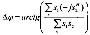
где s1, s2 - сигналы виртуальных излучателей, выражение ![]()
![]()
В исследуемой системе (фиг. 1) формируется четыре виртуальных канала, что дает возможность измерения разности фаз между каждыми двумя виртуальными излучателями, расстояние между которыми позволяет однозначно измерять азимут. К примеру, измеряя разность фаз между каналами K1K2, K2K3, K3K4, соответственно Δφ1, Δφ2, Δφ3, получим аналог скользящего окна по каналам виртуальной апертуры (фиг. 2).In the studied system (Fig. 1) four virtual channels are formed, which makes it possible to measure the phase difference between each two virtual emitters, the distance between which allows you to unambiguously measure the azimuth. For example, measuring the phase difference between the channels K1K2, K2K3, K3K4, respectively Δφ 1 , Δφ 2 , Δφ 3 , we obtain an analogue of the sliding window through the channels of the virtual aperture (Fig. 2).
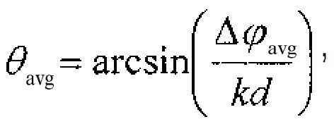
В результате, усредняя серию из трех Δφср измерений, абсолютная ошибка измерения азимута уменьшается в ![]()
![]()

где k=2π/λ - волновое число.where k = 2π / λ is the wave number.
Техническое решение является новым, поскольку из общедоступных сведений не известен способ, позволяющий однозначно измерять азимут в сверхширокополосном НРЛ с высокой точностью и получить высокую разрешающую способность по азимуту.The technical solution is new, since there is no known method that makes it possible to unambiguously measure the azimuth in an ultra-wideband NRL with high accuracy and to obtain a high azimuth resolution.
Особенность методов моноимпульсной радиолокации при измерении угловых направлений заключается в том, что в каждом из элементов разрешения по дальности находится только одна блестящая точка. В ближней радиолокации, как правило, используются малоразмерные апертуры с широкой диаграммой направленности (ДН), если в пределах ДН находятся цели, не разрешаемые по дальности, разрешить их по азимуту также невозможно.A feature of monopulse radar methods for measuring angular directions is that in each of the elements of range resolution there is only one brilliant point. In near radar, as a rule, small-sized apertures with a wide radiation pattern (LH) are used, if within the LN there are targets that are not resolvable in range, it is also impossible to resolve them in azimuth.
Формирование четырех виртуальных приемных каналов позволяет улучшить разрешение по азимуту, так как в виртуальных каналах сохраняется линейный сдвиг фаз в зависимости от азимутального направления. Суммирование четырех сигналов дает обужение ДН виртуальной антенной решетки (АР) по азимуту аналогично реальной линейной АР. То есть суммирование сигналов в виртуальных каналах дает улучшение разрешающей способности по азимуту. Обужение ДН по азимуту сокращает сектор обзора пространства. Для расширения сектора обзора необходимо принять во внимание то, что все четыре виртуальных канала в отличие от элементов реальной АР работают независимо и ДН каждого канала соответствует ДН элементарного излучателя. Суммирование сигналов виртуальных вибраторов с соответствующими линейными задержками τ (фиг. 3) позволяет организовать сканирование по азимуту [6, стр. 8].The formation of four virtual receiving channels allows us to improve the azimuth resolution, since the linear phase shift is preserved in the virtual channels depending on the azimuthal direction. The summation of the four signals gives the narrowing of the beam pattern of the virtual antenna array (AR) in azimuth, similar to a real linear AR. That is, the summation of the signals in the virtual channels gives an improvement in azimuth resolution. The narrowing of the azimuthal pattern reduces the space sector. To expand the viewing sector, it is necessary to take into account the fact that all four virtual channels, in contrast to the elements of a real AR, operate independently and the bottom of each channel corresponds to the bottom of the elementary emitter. Summing the signals of virtual vibrators with the corresponding linear delays τ (Fig. 3) allows you to organize scanning in azimuth [6, p. 8].
Формирование при этом четырех-пяти ортогональных лучей (фиг. 4) покрывает всю зону обзора пространства, что позволяет сократить время поиска объектов, содержащих радиоэлектронные элементы.The formation of four to five orthogonal rays (Fig. 4) covers the entire field of view of space, which allows to reduce the search time for objects containing electronic components.
Таким образом, формирование виртуальной апертуры позволяет однозначно измерять азимутальную координату цели интерферометрическим методом с высокой точностью с помощью скользящего окна по каналам виртуальной апертуры в сверхширокополосном НРЛ и дополнительно увеличить разрешающую способность по азимуту.Thus, the formation of a virtual aperture makes it possible to unambiguously measure the azimuthal coordinate of a target using the interferometric method with high accuracy using a sliding window through the channels of a virtual aperture in an ultra-wideband NRL and to further increase the azimuth resolution.
ЛитератураLiterature
1. Чапурский В.В. Избранные задачи теории сверхширокополосных радиолокационных систем. М.: МГТУ им. Н.Э. Баумана, 2012, 279 с.1. Chapursky V.V. Selected problems of the theory of ultra-wideband radar systems. M .: MSTU im. N.E. Bauman, 2012, 279 p.
2. Патент РФ на изобретение №2397509 «Нелинейная РЛС с синтезированной апертурой антенны», G01S 13/90. Опубликовано: 20.08.2010.2. RF patent for the invention No. 2397509 "Non-linear radar with a synthesized aperture of the antenna", G01S 13/90. Published: 08/20/2010.
3. Родс Д.Р. Введение в моноимпульсную радиолокацию. М.: Советское радио, 1960, 160 с.3. Rhodes D.R. Introduction to monopulse radar. M .: Soviet radio, 1960, 160 p.
4. Черняк B.C. О новом направлении в радиолокации: MIMO РЛС // Прикладная радиоэлектроника, 2009, Том 8, №4, с. 477-489.4. Chernyak B.C. About a new direction in radar: MIMO radar // Applied Radioelectronics, 2009, Volume 8, No. 4, p. 477-489.
5. Бурдик B.C. Анализ гидроакустических систем. Л.: Судостроение, 1988, 392 с.5. Burdick B.C. Analysis of sonar systems. L .: Shipbuilding, 1988, 392 p.
6. Вендик О.Г. Атенны с немеханическим движением луча. М.: Советское радио, 1965, 360 с.6. Vendik O.G. Aerials with non-mechanical beam movement. M .: Soviet Radio, 1965, 360 p.
Claims (1)

Priority Applications (1)
| Application Number | Priority Date | Filing Date | Title |
|---|---|---|---|
| RU2015132508/07A RU2593595C1 (en) | 2015-08-04 | 2015-08-04 | Method of measuring angular coordinates in nonlinear radar |
Applications Claiming Priority (1)
| Application Number | Priority Date | Filing Date | Title |
|---|---|---|---|
| RU2015132508/07A RU2593595C1 (en) | 2015-08-04 | 2015-08-04 | Method of measuring angular coordinates in nonlinear radar |
Publications (1)
| Publication Number | Publication Date |
|---|---|
| RU2593595C1 true RU2593595C1 (en) | 2016-08-10 |
Family
ID=56613237
Family Applications (1)
| Application Number | Title | Priority Date | Filing Date |
|---|---|---|---|
| RU2015132508/07A RU2593595C1 (en) | 2015-08-04 | 2015-08-04 | Method of measuring angular coordinates in nonlinear radar |
Country Status (1)
| Country | Link |
|---|---|
| RU (1) | RU2593595C1 (en) |
Cited By (3)
| Publication number | Priority date | Publication date | Assignee | Title |
|---|---|---|---|---|
| RU2642883C1 (en) * | 2017-01-31 | 2018-01-29 | Акционерное общество "Всероссийский научно-исследовательский институт радиотехники" | Method of angular superresolution by digital antenna arrays |
| RU183565U1 (en) * | 2018-01-25 | 2018-09-25 | АО "Группа Защиты - ЮТТА" | MOBILE DETECTION AND SUPPRESSION COMPLEX OF RADIO-CONTROLLED EXPLOSIVE DEVICES |
| CN110940958A (en) * | 2019-10-30 | 2020-03-31 | 湖北大学 | Radar resolution measuring method |
Citations (6)
| Publication number | Priority date | Publication date | Assignee | Title |
|---|---|---|---|---|
| US5191343A (en) * | 1992-02-10 | 1993-03-02 | United Technologies Corporation | Radar target signature detector |
| WO2002014891A2 (en) * | 2000-08-16 | 2002-02-21 | Raytheon Company | Automotive radar systems and techniques |
| RU2307375C1 (en) * | 2006-04-28 | 2007-09-27 | Открытое акционерное общество "Научно-исследовательский институт измерительных приборов" (ОАО "НИИИП") | Method for measurement of elevation angle of low-altitude target and radar for its realization |
| RU2317562C2 (en) * | 2005-06-14 | 2008-02-20 | Василий Васильевич Ефанов | Method for measurement of angular target co-ordinates and device for its realization |
| RU2530542C1 (en) * | 2013-04-09 | 2014-10-10 | Открытое акционерное общество "Федеральный научно-производственный центр "Нижегородский научно-исследовательский институт радиотехники" | Method and device for measurement of angular height of object of search in surveillance non-linear radars |
| US20140313071A1 (en) * | 2013-04-17 | 2014-10-23 | John W. McCorkle | System and method for nonlinear radar |
-
2015
- 2015-08-04 RU RU2015132508/07A patent/RU2593595C1/en active
Patent Citations (6)
| Publication number | Priority date | Publication date | Assignee | Title |
|---|---|---|---|---|
| US5191343A (en) * | 1992-02-10 | 1993-03-02 | United Technologies Corporation | Radar target signature detector |
| WO2002014891A2 (en) * | 2000-08-16 | 2002-02-21 | Raytheon Company | Automotive radar systems and techniques |
| RU2317562C2 (en) * | 2005-06-14 | 2008-02-20 | Василий Васильевич Ефанов | Method for measurement of angular target co-ordinates and device for its realization |
| RU2307375C1 (en) * | 2006-04-28 | 2007-09-27 | Открытое акционерное общество "Научно-исследовательский институт измерительных приборов" (ОАО "НИИИП") | Method for measurement of elevation angle of low-altitude target and radar for its realization |
| RU2530542C1 (en) * | 2013-04-09 | 2014-10-10 | Открытое акционерное общество "Федеральный научно-производственный центр "Нижегородский научно-исследовательский институт радиотехники" | Method and device for measurement of angular height of object of search in surveillance non-linear radars |
| US20140313071A1 (en) * | 2013-04-17 | 2014-10-23 | John W. McCorkle | System and method for nonlinear radar |
Non-Patent Citations (1)
| Title |
|---|
| РОДС Д.Р. Введение в моноимпульсную радиолокацию. Москва,Советское радио, 1960, с.15. * |
Cited By (4)
| Publication number | Priority date | Publication date | Assignee | Title |
|---|---|---|---|---|
| RU2642883C1 (en) * | 2017-01-31 | 2018-01-29 | Акционерное общество "Всероссийский научно-исследовательский институт радиотехники" | Method of angular superresolution by digital antenna arrays |
| RU183565U1 (en) * | 2018-01-25 | 2018-09-25 | АО "Группа Защиты - ЮТТА" | MOBILE DETECTION AND SUPPRESSION COMPLEX OF RADIO-CONTROLLED EXPLOSIVE DEVICES |
| CN110940958A (en) * | 2019-10-30 | 2020-03-31 | 湖北大学 | Radar resolution measuring method |
| CN110940958B (en) * | 2019-10-30 | 2023-03-31 | 湖北大学 | Radar resolution measuring method |
Similar Documents
| Publication | Publication Date | Title |
|---|---|---|
| US10754018B2 (en) | Frequency modulated continuous wave antenna system | |
| JP2021183985A (en) | Mimo radar sensor for automobile | |
| WO2018025421A1 (en) | Object detection apparatus and object detection method | |
| US20210026004A1 (en) | Frequency Modulated Continuous Wave Antenna System | |
| Gil-Martínez et al. | Direction finding of RFID tags in UHF band using a passive beam-scanning leaky-wave antenna | |
| RU2593595C1 (en) | Method of measuring angular coordinates in nonlinear radar | |
| JP7120919B2 (en) | Object detection device and object detection method | |
| Li et al. | Low-cost millimeter wave frequency scanning based synthesis aperture imaging system for concealed weapon detection | |
| RU2402034C1 (en) | Radar technique for determining angular position of target and device for realising said method | |
| RU2711400C1 (en) | Method of determining the emitter or direction-finding antennas above the earth's surface | |
| Lesturgie | Some relevant applications of MIMO to radar | |
| Chen et al. | Beam split algorithm for height measurement with meter-wave MIMO radar | |
| Alistarh et al. | Millimetre-wave FMCW MIMO radar system development using broadband SIW antennas | |
| Alli et al. | Beamforming for through-the-wall radar imaging | |
| Kang et al. | Investigation of stepped-frequency hybrid modulation radar for respiration monitoring, 2-D localization, and moving target tracking | |
| Ram et al. | Through-wall propagation effects on Doppler-enhanced frontal radar images of humans | |
| US20210325524A1 (en) | Angle measuring device, angle measuring method, and in-vehicle device | |
| Yan et al. | A novel fast near-field electromagnetic imaging method for full rotation problem | |
| Kobayashi et al. | Simple near-field to far-field transformation method using antenna array-factor | |
| RU2692467C2 (en) | Radar method | |
| Zheng et al. | 4D automotive radar exploiting sparse array optimization and compressive sensing | |
| RU2657355C1 (en) | Method of the virtual phased antenna array creating | |
| RU2530542C1 (en) | Method and device for measurement of angular height of object of search in surveillance non-linear radars | |
| Ma et al. | Corner Multipath in Through-the-Wall Radar Imaging based on Compressive Sensing | |
| RU2557251C1 (en) | Method for polarisation-sensitive search for small-size mobile objects |