RU2592908C1 - Method of extracting stuck pipes string of flexible pipes from well - Google Patents
Method of extracting stuck pipes string of flexible pipes from well Download PDFInfo
- Publication number
- RU2592908C1 RU2592908C1 RU2015112452/03A RU2015112452A RU2592908C1 RU 2592908 C1 RU2592908 C1 RU 2592908C1 RU 2015112452/03 A RU2015112452/03 A RU 2015112452/03A RU 2015112452 A RU2015112452 A RU 2015112452A RU 2592908 C1 RU2592908 C1 RU 2592908C1
- Authority
- RU
- Russia
- Prior art keywords
- pipe
- well
- string
- stuck
- flexible
- Prior art date
Links
Images

Abstract
Description
Изобретение относится к нефтегазодобывающей промышленности, а именно к извлечению прихваченной колонны гибких труб из скважины с помощью гибкой трубы меньшего диаметра, спускаемой в скважину.The invention relates to the oil and gas industry, namely, to extract a stuck string of flexible pipes from a well using a flexible pipe of smaller diameter, lowered into the well.
Месторождения Западной Сибири вступили в завершающую скважину разработки, характеризующуюся низкими пластовыми давлениями, большой степенью обводненности залежи и разрушением призабойной зоны пласта. В этих условиях ремонт скважин чаще всего осуществляется с использованием гибкой трубы колтюбинговой установки. Нередко этот ремонт осложняется различными авариями, включая прихват спущенной в ремонтируемую скважину колонны гибких труб [Кустышев А.В. Сложные ремонты скважин. - М.: ИРЦ Газпром, 2010. - 165 с.].The fields of Western Siberia entered the final development well, characterized by low reservoir pressures, a high degree of water cut in the reservoir, and destruction of the bottomhole formation zone. Under these conditions, well repair is most often carried out using a flexible pipe of a coiled tubing installation. Often this repair is complicated by various accidents, including the seizure of a string of flexible pipes lowered into a well being repaired [Kustyshev A.V. Complex well repairs. - M .: IRC Gazprom, 2010. - 165 p.].
Известен способ извлечения прихваченной колонны труб из скважины [Амиров А.Д., Овнатанов С.Е., Яшин А.С. Капитальный ремонт нефтяных и газовых скважин. - М.: Недра, 1975. - 194 с].A known method of extracting a stuck pipe string from a well [Amirov A.D., Ovnatanov S.E., Yashin A.S. Overhaul of oil and gas wells. - M .: Nedra, 1975. - 194].
Недостатком этого способа является невозможность извлечения прихваченной колонны гибких труб из скважины с помощью спускаемой в аварийную скважину новой гибкой трубы по причине отсутствия возможности спуска ее в скважину, в которой уже находится колонна гибких труб, а также отсутствие специального срезного и ловильного оборудования.The disadvantage of this method is the inability to extract the stuck string of flexible pipes from the well with the help of a new flexible pipe being lowered into the emergency well due to the inability to lower it into the well in which the flexible pipe string is already located, as well as the absence of special shear and fishing equipment.
Известен способ извлечения прихваченной колонны труб из скважины [Будников А.Д., Овнатанов С.Е., Яшин А.С. Осложнения при ремонте нефтяных и газовых скважин. - М.: Недра, 1975. - 194 с.].A known method of extracting a stuck pipe string from a well [Budnikov A.D., Ovnatanov S.E., Yashin A.S. Complications in the repair of oil and gas wells. - M .: Nedra, 1975. - 194 p.].
Недостатком этого способа является невозможность извлечения прихваченной колонны гибких труб из скважины с помощью спускаемой в аварийную скважину новой гибкой трубы по причине отсутствия возможности спуска ее в скважину, в которой уже находится колонна гибких труб, а также отсутствие специального срезного и ловильного оборудования.The disadvantage of this method is the inability to extract the stuck string of flexible pipes from the well with the help of a new flexible pipe being lowered into the emergency well due to the inability to lower it into the well in which the flexible pipe string is already located, as well as the absence of special shear and fishing equipment.
Известен способ извлечения прихваченной колонны гибких труб из скважины, взятый за прототип [Булатов А.И. Колтюбинговые технологии при бурении, заканчивании и ремонте нефтяных и газовых скважин. Справочное пособие. - М.: Изд-во «Просвещение-Юг», 2008. - С. 320].A known method of extracting a stuck string of flexible pipes from a well, taken as a prototype [Bulatov A.I. Coiled tubing technology for drilling, completion and repair of oil and gas wells. Reference manual. - M .: Publishing house "Enlightenment-South", 2008. - S. 320].
Недостатком этого способа является недостаточная эффективность извлечения прихваченной колонны гибких труб, особенно невозможность ее извлечения из скважины, в которой уже находится ранее спущенная колонна гибких труб.The disadvantage of this method is the insufficient efficiency of extraction of the stuck string of flexible pipes, especially the inability to extract it from the well, in which the previously lowered string of flexible pipes is already located.
Задача, стоящая при создании изобретения, заключается в том, чтобы обеспечить возможность извлечения прихваченной колонны гибких труб из скважины с помощью гибкой трубы, спускаемой в аварийную скважину.The challenge faced by the invention is to enable retrieval of a stuck tubing string from a well using a flexible tubing lowered into an emergency well.
При осуществлении изобретения поставленная задача решается за счет достижения технического результата, который заключается в повышении надежности извлечения прихваченной колонну гибких труб из скважины без ее глушения, сокращении продолжительности ремонтных работ, снижении затрат на проведение работ и стоимость ремонта скважиныIn the implementation of the invention, the task is solved by achieving a technical result, which consists in increasing the reliability of extracting a stuck string of flexible pipes from a well without killing it, reducing the duration of repair work, reducing the cost of work and the cost of repairing a well
Задача и технический результат достигаются тем, что способ извлечения прихваченной колонны гибких труб из аварийной скважины, находящейся под давлением, включает захват прихваченной колонны гибких труб спайдерными плашками блока превенторов, ее герметизацию трубными плашками и срез гибкой трубы срезными плашками, извлечение отрезанной части колонны из скважины, пропуск через инжектор гибкой трубы меньшего диаметра с обратным клапаном и переводником до уровня выше срезных плашек блока превенторов, раскрепление наземного оборудования колтюбинговой установки выше превентора с трубными плашками от устья ремонтируемой скважины, отсоединение и подвешивание его с помощью грузоподъемного механизма, вытягивание гибкой трубы меньшего диаметра из инжектора, монтаж на устье выше превентора с трубными плашками шлюзовой камеры, спуск в нее срезной сборки из трубореза, забойного двигателя и гидравлического якоря с внутренним диаметром, меньшим наружного диаметра оставшейся в скважине прихваченной колонны гибких труб, присоединение срезной сборки к переводнику гибкой трубы меньшего диаметра, монтаж на шлюзовой камере отсоединенной части наземного оборудования колтюбинговой установки, спуск гибкой трубы меньшего диаметра со срезной сборкой в скважину до глубины на 1-2 м выше места прихвата оставшейся части прихваченной колонны гибких труб, закрепление сборки во внутренней полости прихваченной гибкой трубы с помощью гидравлического якоря малого диаметра, резку прихваченной колонны гибких труб с помощью трубореза, при создании циркуляции промывочной жидкости до ее появления в кольцевом пространстве между прихваченной колонной гибких труб и спущенной гибкой трубой меньшего диаметра, подъем гибкой трубы меньшего диаметра со срезной сборкой до превентора с трубными плашками, закрытие трубных плашек, раскрепление наземного оборудования колтюбинговой установки выше превентора с трубными плашками от устья скважины, отсоединение и подвешивание его с помощью грузоподъемного механизма, извлечение из шлюзовой камеры срезной сборки, отсоединение ее от переводника гибкой трубы меньшего диаметра, соединение наземного оборудования колтюбинговой установки с устьевым оборудованием скважины выше превентора с трубными плашками, удаление отрезанной части ранее прихваченной колонны гибких труб из скважины, герметизацию скважины глухими плашками блока превенторов, раскрепление наземного оборудования колтюбинговой установки выше превентора с трубными плашками от устьевого оборудования скважины, отсоединение и подвешивание его с помощью грузоподъемного механизма, спуск в шлюзовую камеру ловильной сборки из ловителя в виде метчика, гидравлического домкрата, забойного двигателя и гидравлического якоря с наружным диаметром, равным внутреннему диаметру оставшейся в скважине прихваченной колонны гибких труб, присоединение ловильной сборки к переводнику гибкой трубы меньшего диаметра, монтаж на шлюзовой камере отсоединенной части наземного оборудования колтюбинговой установки, спуск гибкой трубы меньшего диаметра с ловильной сборкой в скважину до глубины на 1-2 м выше головы отрезанной части прихваченной колонны гибких труб, при минимальной скорости спуска осуществление ввода ловильной сборки во внутреннюю полость прихваченной колонны труб, вращение ловителя для захвата и крепления его с прихваченной колонной труб с помощью забойного двигателя при создании циркуляции промывочной жидкости до ее появления в кольцевом пространстве между прихваченной колонной гибких труб и спущенной гибкой трубой меньшего диаметра, закрепление ловильной сборки во внутренней полости эксплуатационной колонны с помощью гидравлического якоря большего диаметра, вытягивание прихваченной колонны гибких труб с помощью гидравлического домкрата с усилием не более 700 кН и извлечение ранее прихваченной колонны гибких труб из скважины.The objective and technical result is achieved in that a method for extracting a stuck string of flexible pipes from an emergency well under pressure includes gripping the stuck string of flexible pipes with spider dies of the preventer unit, sealing it with pipe dies and cutting the flexible pipe with shear dies, removing the cut part of the column from the well , passage through an injector of a smaller diameter flexible pipe with a check valve and sub to a level above the shear dies of the preventer unit, unfastening of ground equipment coiled tubing installation above the preventer with pipe dies from the mouth of the well being repaired, disconnecting and suspending it using a lifting mechanism, pulling a smaller flexible pipe from the injector, mounting on the mouth above the preventer with pipe dies of the lock chamber, lowering the shear assembly from the pipe cutter, downhole motor and a hydraulic anchor with an inner diameter smaller than the outer diameter of the sticky string of flexible pipes remaining in the well, connecting the shear assembly to the flexible pipe sub of smaller diameter, installation of a coiled tubing installation on the airlock chamber of the disconnected part of the ground equipment, lowering the flexible pipe of smaller diameter with shear assembly to a depth of 1-2 m above the sticking point of the remaining part of the stuck string of flexible pipes, fixing the assembly in the inner cavity of the stuck flexible pipe with using a hydraulic anchor of small diameter, cutting a stuck string of flexible pipes with a pipe cutter, while creating a circulation of flushing fluid until it appears in the annular space between a collapsed string of flexible pipes and a deflated flexible pipe of a smaller diameter, lifting a flexible pipe of a smaller diameter with shear assembly to a preventer with pipe dies, closing the pipe dies, unfastening the ground equipment of the coiled tubing installation above the preventer with pipe dies from the wellhead, disconnecting and suspending it using a load mechanism, removing the shear assembly from the lock chamber, disconnecting it from the sub of the flexible pipe of smaller diameter, connecting the ground equipment of the coiled tubing installations with wellhead equipment above the preventer with pipe dies, removing the cut-off portion of the previously stuck string of flexible pipes from the well, sealing the well with blind dies of the preventer unit, unfastening the ground equipment of the coiled tubing installation above the preventer with pipe dies from the wellhead equipment, disconnecting and suspending it using lifting mechanism, descent into the lock chamber of the fishing assembly from the catcher in the form of a tap, hydraulic jack, downhole motor and a hydraulic anchor with an outer diameter equal to the inner diameter of the sticky string of pipes remaining in the well, attaching the fishing assembly to the sub of the flexible pipe of smaller diameter, mounting on the lock chamber of the disconnected part of the ground equipment of the coiled tubing installation, lowering the smaller flexible pipe with the fishing assembly into the well to a depth 1-2 m above the head of the cut-off part of the stuck string of flexible pipes, with a minimum descent speed, the introduction of the fishing assembly into the inner polo tacked pipe string, rotation of the catcher to grip and fasten it with the stuck pipe string using a downhole motor to circulate the flushing fluid until it appears in the annular space between the stuck pipe string and the deflated flexible pipe of a smaller diameter, fixing the fishing assembly in the internal cavity columns with a larger diameter hydraulic anchor, pulling a stuck string of flexible pipes with a hydraulic jack with a force of not more than 700 k H and the extraction of previously stuck string of flexible pipes from the well.
Заявляемая совокупность существенных признаков обеспечивает возможность извлечения прихваченной колонны гибких труб из скважины с помощью новой гибкой трубы меньшего диаметра, спускаемой в эту же аварийную скважину под давлением без ее глушения.The claimed combination of essential features makes it possible to extract the stuck string of flexible pipes from the well using a new flexible pipe of smaller diameter, lowered into the same emergency well under pressure without killing it.
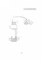
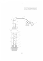
На фиг. 1. приведена схема компоновки оборудования аварийной скважины с прихваченной колонной гибких труб, на фиг. 2 - то же, при отрезании прихваченной колонны гибких труб, на фиг. 3 - то же, при извлечении прихваченной колонны гибких труб.In FIG. 1. The layout diagram of the equipment of an emergency well with a stuck string of flexible pipes is shown; FIG. 2 - the same, when cutting off the stuck string of flexible pipes, in FIG. 3 - the same, when removing the stuck column of flexible pipes.
Способ реализуют следующим образом.The method is implemented as follows.
В аварийную скважину, находящуюся под давлением и с установленной на устье колтюбинговой установкой, включающей собственно установку 1 с барабаном 2 гибких труб 3, направляющий желоб 4, инжектор 5, блок превенторов 6 с превентором со срезными плашками 7, с превентором со спайдерными клиновыми плашками 8, с превентором с трубными плашками 9, с превентором с глухими плашками 10, размещенными на устьевом оборудовании 11, первоначально осуществляют захват прихваченной в скважине колонны гибких труб 3 спайдерными (клиновыми) плашками превентора 8, ее герметизацию трубными плашками превентора 9 и срез колонны гибких труб 3 срезными плашками превентора 7, извлечение отрезанной части колонны гибких труб 3 из скважины.In an emergency well, which is under pressure and with a coiled tubing installation installed on the mouth, including the
Далее через инжектор 5 пропускают гибкую трубу меньшего диаметра 12 с обратным клапаном 13 и переводником 14 до уровня выше срезных плашек 7 блока превенторов 6. Осуществляют раскрепление наземного оборудования колтюбинговой установки 1 выше превентора 10 с трубными плашками от устьевого оборудования 11 ремонтируемой скважины, отсоединяют и подвешивают его с помощью грузоподъемного механизма, например автокрана (не показано). Вытягивают гибкую трубу меньшего диаметра 12 из инжектора 5 и монтируют на устьевом оборудовании 11 выше превентора 9 с трубными плашками шлюзовую камеру 15. Спускают в нее срезную сборку, включающую труборез 16, забойный двигатель 17 и гидравлический якорь малого диаметра 18 с внутренним диаметром, меньшим наружного диаметра оставшейся в скважине прихваченной колонны гибких труб 3, например, песчаной пробкой 19, образовавшейся по причине разрушения горной породы призабойной зоны продуктивного пласта 20.Next, a flexible pipe of
Присоединяют срезную сборку к переводнику 14 гибкой трубы меньшего диаметра 12. Монтируют на шлюзовой камере 15 отсоединенную часть наземного оборудования колтюбинговой установки, включая превентор 7 со срезными плашками.Connect the shear assembly to the
Затем спускают гибкую трубу меньшего диаметра 12 со срезной сборкой в скважину до глубины на 1-2 м выше места прихвата оставшейся части прихваченной колонны гибких труб 3. Закрепляют срезную сборку во внутренней полости прихваченной гибкой трубы 3 с помощью гидравлического якоря малого диаметра 18. Далее осуществляют резку прихваченной колонны гибких труб 3 с помощью трубореза 16 при создании циркуляции промывочной жидкости до ее появления в кольцевом пространстве между прихваченной колонной гибких труб 3 и спущенной гибкой трубой меньшего диаметра 12. После чего гибкую трубу меньшего диаметра 12 со срезной сборкой поднимают до превентора с трубными плашками 9, трубные плашки 9 закрывают, осуществляя герметизацию гибкой трубы меньшего диаметра 12.Then lower the flexible pipe of
Раскрепляют наземное оборудование колтюбинговой установки выше превентора с трубными плашками 9 от устьевого оборудования 11 ремонтируемой скважины, отсоединяют и подвешивают его с помощью грузоподъемного механизма, например, с помощью автокрана. Извлекают из шлюзовой камеры 15 срезную сборку, отсоединяют ее от переводника 14 гибкой трубы меньшего диаметра 12. Соединяют наземное оборудование колтюбинговой установки 1 с устьевым оборудованием 11 ремонтируемой скважины выше превентора с трубными плашками 9.The ground equipment of the coiled tubing unit above the preventer with
Удаляют из скважины отрезанную часть ранее прихваченной колонны гибких труб 3, герметизируют скважину глухими плашками 10 блока превенторов 6.The cut-off part of the previously stuck string of
Раскрепляют наземное оборудование колтюбинговой установки выше превентора с трубными плашками 9 от устьевого оборудования 11 ремонтируемой скважины, отсоединяют и подвешивают его с помощью грузоподъемного механизма.The ground equipment of the coiled tubing unit above the preventer with
Спускают в шлюзовую камеру 15 ловильную сборку, состоящую из ловителя 21, например метчика, гидравлического домкрата 22, забойного двигателя 17 и гидравлического якоря большого диаметра 23 с наружным диаметром, равным внутреннему диаметру оставшейся в скважине прихваченной колонны гибких труб 3. Присоединяют ловильную сборку к переводнику 14 гибкой трубы меньшего диаметра 12, монтируют на шлюзовой камере 15 отсоединенную часть наземного оборудования колтюбинговой установки.The fishing assembly is lowered into the
Спускают гибкую трубу меньшего диаметра 12 с ловильной сборкой в скважину до глубины на 1-2 м выше головы отрезанной части прихваченной колонны гибких труб 3. Осторожно вводят при минимальной скорости спуска ловильную сборку во внутреннюю полость прихваченной колонны труб 3. Осуществляют вращение ловителя 21 (метчика), для захвата и крепления его с прихваченной колонной труб 3 с помощью забойного двигателя 17 при создании циркуляции промывочной жидкости до появлении ее в кольцевом пространстве между прихваченной колонной гибких труб 3 и спущенной гибкой трубой меньшего диаметра 12. Закрепляют ловильную сборку во внутренней полости эксплуатационной колонны 24 с помощью гидравлического якоря большего диаметра 23.A flexible pipe of
Применение метчика в качестве ловителя возможно в связи с тем, что извлечение колонны гибких труб происходит при их прихвате, а не при обрыве и падении, когда колонна гибких труб претерпевает значительную деформацию и повреждения, когда возможно появление трещин в теле гибких труб и при нарезании резьбы в теле таких труб возможно дальнейшее развитие и расширение трещин, приводящих к последующему обрыву колонны гибких труб из зацепления с метчиком. В случае прихвата колонна гибких труб не подвержена деформации и в теле труб нет повреждений, а значит, можно в качестве ловителя применять метчик. Причем для повышения надежности извлечения прихваченной колонны гибких труб можно применять метчик с наружным диаметром муфтовой части метчика несколько большим внутреннего диаметра прихваченной колонны гибких труб, но не большим их наружного диаметра. Вытягивают прихваченную колонну гибких труб 3 из прихватившей ее песчаной пробки 19 с помощью гидравлического домкрата 22. Вытягивание колонны гибких труб 3 происходит за счет вертикального перемещения его выходной штанги гидравлического домкрата 22, размещенной во внутренней полости гидравлического домкрата 22 с усилием не более 700 кН.The use of a tap as a catcher is possible due to the fact that the extraction of the string of flexible pipes occurs when they are caught, and not when it breaks and falls, when the string of flexible pipes undergoes significant deformation and damage, when cracks in the body of the flexible pipes and when cutting threads are possible in the body of such pipes, further development and expansion of cracks is possible, leading to subsequent breakage of the string of flexible pipes from engagement with the tap. In case of sticking, the string of flexible pipes is not subject to deformation and there is no damage in the pipe body, which means that a tap can be used as a catcher. Moreover, to increase the reliability of extracting the stuck string of flexible pipes, you can use a tap with an outer diameter of the coupling part of the tap slightly larger than the inner diameter of the stuck string of flexible pipes, but not large of their outer diameter. The
В заключении из скважины извлекают уже свободную от песчаной пробки 19 ранее прихваченную колонну гибких труб 3.In conclusion, the previously stuck string of
Предлагаемый способ позволяет надежно и с большой степенью вероятности извлечь прихваченную колонну гибких труб из скважины, сократить продолжительность ремонтных работ с 12 месяцев до трех, снизить затраты на проведение работ и стоимость ремонта скважины в 3-4 раза.The proposed method allows reliably and with a high degree of probability to remove the stuck string of flexible pipes from the well, reduce the duration of the repair work from 12 months to three, reduce the cost of the work and the cost of repairing the well by 3-4 times.
Claims (1)
Priority Applications (1)
| Application Number | Priority Date | Filing Date | Title |
|---|---|---|---|
| RU2015112452/03A RU2592908C1 (en) | 2015-04-06 | 2015-04-06 | Method of extracting stuck pipes string of flexible pipes from well |
Applications Claiming Priority (1)
| Application Number | Priority Date | Filing Date | Title |
|---|---|---|---|
| RU2015112452/03A RU2592908C1 (en) | 2015-04-06 | 2015-04-06 | Method of extracting stuck pipes string of flexible pipes from well |
Publications (1)
| Publication Number | Publication Date |
|---|---|
| RU2592908C1 true RU2592908C1 (en) | 2016-07-27 |
Family
ID=56557105
Family Applications (1)
| Application Number | Title | Priority Date | Filing Date |
|---|---|---|---|
| RU2015112452/03A RU2592908C1 (en) | 2015-04-06 | 2015-04-06 | Method of extracting stuck pipes string of flexible pipes from well |
Country Status (1)
| Country | Link |
|---|---|
| RU (1) | RU2592908C1 (en) |
Cited By (2)
| Publication number | Priority date | Publication date | Assignee | Title |
|---|---|---|---|---|
| CN114809970A (en) * | 2022-04-18 | 2022-07-29 | 中国石油化工股份有限公司 | Coiled tubing built-in hanger fisher and method for shale gas well sand jam |
| CN115162999A (en) * | 2021-04-07 | 2022-10-11 | 中国石油天然气集团有限公司 | Large-diameter continuous gas production pipe column putting construction method |
Citations (3)
| Publication number | Priority date | Publication date | Assignee | Title |
|---|---|---|---|---|
| SU794182A1 (en) * | 1979-02-27 | 1981-01-07 | Ухтинский индустриальный институт | Device for eliminating emergencies associated with drill pipes |
| SU1682523A1 (en) * | 1989-01-03 | 1991-10-07 | Донецкий политехнический институт | Device for recovery of case pipes |
| US6464014B1 (en) * | 2000-05-23 | 2002-10-15 | Henry A. Bernat | Downhole coiled tubing recovery apparatus |
-
2015
- 2015-04-06 RU RU2015112452/03A patent/RU2592908C1/en not_active IP Right Cessation
Patent Citations (3)
| Publication number | Priority date | Publication date | Assignee | Title |
|---|---|---|---|---|
| SU794182A1 (en) * | 1979-02-27 | 1981-01-07 | Ухтинский индустриальный институт | Device for eliminating emergencies associated with drill pipes |
| SU1682523A1 (en) * | 1989-01-03 | 1991-10-07 | Донецкий политехнический институт | Device for recovery of case pipes |
| US6464014B1 (en) * | 2000-05-23 | 2002-10-15 | Henry A. Bernat | Downhole coiled tubing recovery apparatus |
Non-Patent Citations (2)
| Title |
|---|
| КУСТЫШЕВ Д.А. и др. "Аварийно-восстановительные работы в аварийных скважинах с использованием гибкой трубы", журнал "Технологии добычи и использования углеводородов", N3, 2014. * |
| СИНГУРОВ А. и др. "Опыт извлечения прихваченной трубы", журнал "Нефтесервис" N1 2009. * |
Cited By (3)
| Publication number | Priority date | Publication date | Assignee | Title |
|---|---|---|---|---|
| CN115162999A (en) * | 2021-04-07 | 2022-10-11 | 中国石油天然气集团有限公司 | Large-diameter continuous gas production pipe column putting construction method |
| CN115162999B (en) * | 2021-04-07 | 2023-11-14 | 中国石油天然气集团有限公司 | Large-diameter continuous gas production pipe column throwing construction method |
| CN114809970A (en) * | 2022-04-18 | 2022-07-29 | 中国石油化工股份有限公司 | Coiled tubing built-in hanger fisher and method for shale gas well sand jam |
Similar Documents
| Publication | Publication Date | Title |
|---|---|---|
| US10316626B2 (en) | Buoyancy assist tool | |
| CN103742102B (en) | Presetting system blanking plug and input thereof, fishing tool | |
| CN102777156A (en) | Fracturing method for multi-interval oil and gas wells | |
| CN105804680A (en) | Under-pressure well repairing working device and method of oil-gas field | |
| US10662728B2 (en) | Method and apparatus for stuck pipe mitigation | |
| RU2592908C1 (en) | Method of extracting stuck pipes string of flexible pipes from well | |
| CN205605156U (en) | Workover device is pressed in oil gas field area | |
| US2935130A (en) | Method of and apparatus for opening plugged pipe in a well bore | |
| US11162318B2 (en) | Tool catcher system | |
| CN111779466B (en) | Method for solving problem of shaft blockage of failed prefabricated restrictor through hydraulic sand blasting perforation process | |
| CN104612612A (en) | Hanging and tensioning device, production tubular column and tensioning and tie-back method of coiled tubing | |
| CN216588517U (en) | Shale gas well coiled tubing unfreezes fishing system | |
| CN211598548U (en) | Coiled tubing well drilling hydraulic control release device | |
| RU2631517C1 (en) | Method for mechanised pump operation of wells and device for its implementation | |
| CN110685616B (en) | Well repairing operation method for low-permeability water-sensitive oil well | |
| RU2762039C2 (en) | Extraction system | |
| RU2592924C1 (en) | Method of extracting broken and stuck pipes string of flexible pipes from well | |
| RU2596158C1 (en) | Method of extracting broken and stuck pipes string of flexible pipes of emergency well | |
| US10961809B2 (en) | Systems and methods for smart well bore clean out | |
| CN102296939B (en) | Automatic pressure-balancing expansion-catch integrated expandable tube tool and use method thereof | |
| CN114810021A (en) | Gas well full life cycle coiled tubing completion pipe string and process method thereof | |
| CN208330249U (en) | A kind of outstanding slotting fix tool of expansion tube | |
| RU2614998C1 (en) | Method of deep gas well equipment with tubing string composition | |
| AU2017100355A4 (en) | Method of Live Well Completion | |
| CN114737918B (en) | Wax melting blocking removing device and method |
Legal Events
| Date | Code | Title | Description |
|---|---|---|---|
| MM4A | The patent is invalid due to non-payment of fees |
Effective date: 20180407 |