RU2591978C2 - Oven - Google Patents
Oven Download PDFInfo
- Publication number
- RU2591978C2 RU2591978C2 RU2013154374/13A RU2013154374A RU2591978C2 RU 2591978 C2 RU2591978 C2 RU 2591978C2 RU 2013154374/13 A RU2013154374/13 A RU 2013154374/13A RU 2013154374 A RU2013154374 A RU 2013154374A RU 2591978 C2 RU2591978 C2 RU 2591978C2
- Authority
- RU
- Russia
- Prior art keywords
- elements
- suction
- oven
- baking
- waffle
- Prior art date
Links
Images

Classifications
-
- A—HUMAN NECESSITIES
- A21—BAKING; EDIBLE DOUGHS
- A21B—BAKERS' OVENS; MACHINES OR EQUIPMENT FOR BAKING
- A21B3/00—Parts or accessories of ovens
- A21B3/18—Discharging baked goods from tins
-
- A—HUMAN NECESSITIES
- A21—BAKING; EDIBLE DOUGHS
- A21B—BAKERS' OVENS; MACHINES OR EQUIPMENT FOR BAKING
- A21B1/00—Bakers' ovens
- A21B1/42—Bakers' ovens characterised by the baking surfaces moving during the baking
-
- A—HUMAN NECESSITIES
- A21—BAKING; EDIBLE DOUGHS
- A21B—BAKERS' OVENS; MACHINES OR EQUIPMENT FOR BAKING
- A21B5/00—Baking apparatus for special goods; Other baking apparatus
- A21B5/02—Apparatus for baking hollow articles, waffles, pastry, biscuits, or the like
- A21B5/023—Hinged moulds for baking waffles
-
- A—HUMAN NECESSITIES
- A21—BAKING; EDIBLE DOUGHS
- A21B—BAKERS' OVENS; MACHINES OR EQUIPMENT FOR BAKING
- A21B3/00—Parts or accessories of ovens
- A21B3/07—Charging or discharging ovens
-
- A—HUMAN NECESSITIES
- A21—BAKING; EDIBLE DOUGHS
- A21C—MACHINES OR EQUIPMENT FOR MAKING OR PROCESSING DOUGHS; HANDLING BAKED ARTICLES MADE FROM DOUGH
- A21C15/00—Apparatus for handling baked articles
-
- A—HUMAN NECESSITIES
- A21—BAKING; EDIBLE DOUGHS
- A21C—MACHINES OR EQUIPMENT FOR MAKING OR PROCESSING DOUGHS; HANDLING BAKED ARTICLES MADE FROM DOUGH
- A21C15/00—Apparatus for handling baked articles
- A21C15/02—Apparatus for shaping or moulding baked wafers; Making multi-layer wafer sheets
Abstract
Description
Изобретение относится к духовкам, имеющим бесконечную цепь вафельниц, циркулирующую в духовке, которая содержит вафельницы, содержащие формы для выпекания, состоящие из верхних частей и нижних частей, которые могут быть блокированы в открываемом и закрываемом положении, в которых в процессе выпекания формируются хрустящие хрупкие изделия.The invention relates to ovens having an endless chain of waffle irons circulating in the oven, which contains waffle irons containing baking dishes, consisting of upper parts and lower parts, which can be locked in the open and close position, in which crispy brittle products are formed during baking .
Каждая духовка имеет переднюю часть, заднюю часть, корпус, снабженный наружной теплоизоляцией, пекарную камеру, расположенную внутри теплоизоляции, и бесконечную цепь вафельниц, непрерывно циркулирующую в духовке и перемещающуюся через пекарную камеру. Цепь вафельниц, циркулирующая в духовке, располагается в духовке на замкнутой орбите и продолжается на двух транспортных уровнях, расположенных один над другим через обе части духовки. Цепь вафельниц содержит вафельницы, которые могут открываться и закрываться, и которые могут быть блокированы в закрытом положении, в которых располагаются формы для выпекания, состоящие из верхних частей и нижних частей, которые открываются при открывании вафельниц, и закрываются при закрывании вафельниц. В передней части духовки на орбите цепи вафельниц и по верхнему транспортировочному уровню расположено устройство для разблокировки вафельниц, последовательно в направлении движения вафельниц располагаются устройство для открывания вафельниц, разгрузочная станция, загрузочная станция и устройство для закрывания вафельниц и устройство для блокировки вафельниц. В разгрузочной станции располагается устройство для выемки изделий, которое вынимает выпеченные изделия из открытых вафельниц, и за которым следует верхнее транспортировочное устройство для вынутых выпеченных изделий.Each oven has a front part, a back part, a case equipped with external thermal insulation, a baking chamber located inside the thermal insulation, and an endless chain of waffle irons that continuously circulate in the oven and move through the baking chamber. The chain of waffle irons circulating in the oven is located in the oven in a closed orbit and continues at two transport levels located one above the other through both parts of the oven. The waffle iron chain contains waffle irons that can open and close, and which can be locked in the closed position, in which baking dishes are arranged, consisting of upper parts and lower parts that open when the waffle irons are opened and close when the waffle irons are closed. In the front part of the oven, in the orbit of the waffle iron chain and on the upper transport level, there is a device for unlocking the waffle irons, sequentially in the direction of movement of the waffle irons there is a device for opening waffle irons, an unloading station, a loading station and a device for closing waffle irons and a device for locking waffle irons. In the unloading station, there is a device for the extraction of products, which removes baked products from open waffle irons, and followed by an upper transport device for removed baked products.
В таких духовках текучие заготовки для выпечки обрабатываются и преобразуются в мучные кондитерские изделия в процессе выпекания.In such ovens, fluid billets are processed and converted to flour confectionery during baking.
Заготовки для выпечки приготовляются в миксере. В миксере жидкие ингредиенты заготовки для выпечки и твердые или порошкообразные ингредиенты заготовки для выпечки смешиваются друг с другом. Таким образом, получается бесформенная масса. Бесформенная масса является текучей. Масса имеет жидкую консистенцию, т.е. от жидкотекучей до густотекучей, и иногда кашицеобразную консистенцию. Жидким ингредиентом является, главным образом, вода, составляющая от 42% до 60.0% по весу от заготовки для выпечки. Порошкообразными ингредиентами являются, главным образом, крахмалсодержащие основные компоненты, составляющие от 36% до 56.5% по весу от заготовки для выпечки. Обычно пшеничная мука используется в качестве крахмалсодержащего основного компонента. Крахмалсодержащим основным компонентом также может быть картофельная мука или смесь пшеничной муки и картофельной муки или смесь муки из зерна различных злаковых культур или картофельной муки.Baking blanks are prepared in a mixer. In the mixer, the liquid ingredients of the billet blank and the solid or powdery ingredients of the billet blank are mixed together. Thus, a shapeless mass is obtained. The shapeless mass is fluid. The mass has a liquid consistency, i.e. from fluid to densely flowing, and sometimes a mushy consistency. The liquid ingredient is mainly water, comprising from 42% to 60.0% by weight of the billet. Powdered ingredients are mainly starch-containing main components, comprising from 36% to 56.5% by weight of the billet. Usually, wheat flour is used as a starch-containing main component. The starch-containing main component may also be potato flour or a mixture of wheat flour and potato flour or a mixture of flour from a grain of various cereal crops or potato flour.
Мучные кондитерские изделия, изготавливаемые из таких заготовок для выпечки, могут быть съедобными мучными кондитерскими изделиями, например, вафлями, хрустящими хрупкими вафельными листами для изготовления тонких вафельных слоев, наполненных кремом и т.п.Flour confectionery made from such bakery blanks can be edible flour confectionery, for example, waffles, crispy brittle wafer sheets for making thin wafer layers filled with cream and the like.
Однако, выпеченными изделиями, изготавливаемыми из таких заготовок для выпечки, также могут быть другие изделия, не предусмотренные для потребления. Такие изделия включают в себя, например, упаковочные изделия, например, упаковочные чашки, изготовленные из крахмалсодержащей заготовки для выпечки или предметы одноразовой столовой посуды, например тарелки и чашки, а также ножи, вилки и ложки, изготовленные из крахмалсодержащей заготовки для выпечки.However, baked products made from such baking blanks may also be other products not intended for consumption. Such products include, for example, packaging products, for example, packaging cups made from starch-containing baking blanks or disposable tableware, such as plates and cups, as well as knives, forks and spoons made from starch-containing baking blanks.
Заготовки для выпечки в виде бесформенных масс, от жидких до кашицеобразных, направляются в духовку, цепь вафельниц которой содержит открываемые и закрываемые вафельницы, снабженные блокирующим устройством.Baking blanks in the form of shapeless masses, from liquid to gruel, are sent to the oven, the chain of waffle makers of which contains openable and lockable waffle irons equipped with a locking device.
В духовке бесформенная масса перемещается посредством насоса для теста по линиям для теста в загрузочную станцию. В загрузочной станции бесформенная масса разделяется на порции теста, и порции теста вводятся в открытые формы для выпечки, расположенные в открытых вафельницах, которые перемещаются мимо загрузочной станции в верхний транспортировочный уровень духовки. После введения порций теста вафельницы закрываются. При закрывании вафельниц, формы для выпечки закрываются, и порции теста вкладываются в закрытые формы для выпечки. После закрывания вафельниц, вафельницы блокируются. Циркулирующая цепь вафельниц перемещает закрытые и блокированные вафельницы через пекарную камеру в заднюю часть духовки. Во время перемещения вафельниц через пекарную камеру вафельницы вместе с формами для выпечки нагреваются и при этом нагреваются до температуры выпечки от 150°C (градусов Цельсия) до 250°C (градусов Цельсия). В результате, порции теста, вложенные в формы для выпечки, подвергаются процессу выпекания и выпекаются под давлением в закрытых и блокированных вафельницах. Циркулирующая цепь вафельниц перемещает закрытые и блокированные вафельницы в переднюю часть духовки. Здесь закрытые вафельницы разблокировываются. Циркулирующая цепь вафельниц перемещает закрытые и разблокированные вафельницы в верхний транспортировочный уровень. Во время перемещения по верхнему транспортировочному уровню вафельницы открываются и перемещаются в открытом положении через разгрузочную станцию к загрузочной станции. В разгрузочной станции, выпеченные хрустящие хрупкие изделия в горячем состоянии вынимаются из открытых форм для выпечки, расположенных в открытых вафельницах. Выпеченные изделия вынимаются из духовки в горячем состоянии. Циркулирующая цепь вафельниц перемещает открытые вафельницы с открытыми пустыми формами для выпечки к загрузочной станции. В загрузочной станции порции теста, недавно сформированные из бесформенной массы, снова вводятся в открытые формы для выпечки.In the oven, the formless mass is transported by the dough pump along the dough lines to the loading station. In the loading station, the shapeless mass is divided into portions of the dough, and portions of the test are introduced into open baking dishes located in open waffle irons that move past the loading station to the upper transport level of the oven. After introducing portions of the dough, the waffle irons close. When closing the waffle irons, the baking dish closes, and portions of the dough are inserted into the closed baking dish. After closing the waffle irons, the waffle irons are blocked. The circulating waffle iron chain moves the closed and blocked waffle irons through the baking chamber to the back of the oven. When moving the waffle irons through the baking chamber, the waffle irons along with the baking dish are heated and at the same time heated to a baking temperature from 150 ° C (degrees Celsius) to 250 ° C (degrees Celsius). As a result, portions of dough embedded in baking dishes are baked and baked under pressure in closed and blocked waffle irons. The circulating waffle iron chain moves the closed and blocked waffle irons to the front of the oven. Here, closed waffle irons are unlocked. The waffle iron circulating chain moves the closed and unlocked waffle irons to the upper transport level. When moving along the upper transport level, the waffle irons open and move in the open position through the unloading station to the loading station. At the discharge station, baked, crisp, brittle products are hot taken out of open baking dishes located in open waffle irons. Baked items are taken out of the oven in a hot condition. A circulating waffle iron chain moves open waffle irons with open empty baking dishes to the loading station. In a loading station, portions of dough, newly formed from a shapeless mass, are again introduced into open baking dishes.
Духовки, в которых формы для выпечки, состоящие из верхних частей и нижних частей, находятся в открываемых и закрываемых вафельницах в бесконечной цепи вафельниц, циркулирующей в духовке и перемещающейся через пекарную камеру, известны, например, из документов AT 378470 B1 и US 4438685 A.Ovens in which baking dishes consisting of upper parts and lower parts are located in openable and closed waffle irons in an endless chain of waffle irons circulating in the oven and moving through the baking chamber are known, for example, from documents AT 378470 B1 and US 4438685 A.
Задачей изобретения является усовершенствование духовки упомянутого в начале типа.The objective of the invention is to improve the oven mentioned at the beginning of the type.
В соответствии с изобретением предлагается новая духовка. Новая духовка имеет переднюю часть, заднюю часть, корпус, снабженный наружной теплоизоляцией, пекарную камеру, расположенную внутри теплоизоляции, и бесконечную цепь вафельниц, которая непрерывно циркулирует в духовке и перемещается через пекарную камеру. Цепь вафельниц расположена на замкнутой орбите, которая продолжается на двух транспортных уровнях, расположенных один над другим, через обе части духовки. Цепь вафельниц содержит вафельницы, которые могут открываться и закрываться и которые могут быть блокированы в закрытом положении, в которых располагаются формы для выпечки, состоящие из верхних частей и нижних частей, которые открываются при открывании вафельниц, и закрываются при закрывании вафельниц. В передней части духовки на орбите цепи вафельниц расположено устройство для разблокировки вафельниц. По верхнему транспортировочному уровню последовательно в направлении движения вафельниц расположены устройство для открывания вафельниц, разгрузочная станция, загрузочная станция и устройство для закрывания вафельниц и устройство для блокировки вафельниц. В разгрузочной станции предусмотрено устройство для выемки изделий, которое вынимает выпеченные изделия из открытых вафельниц, и за которым следует верхнее транспортировочное устройство для вынутых выпеченных изделий.In accordance with the invention, a new oven is proposed. The new oven has a front part, a back part, a body equipped with external thermal insulation, a baking chamber located inside the thermal insulation, and an endless chain of waffle irons that continuously circulates in the oven and moves through the baking chamber. The waffle iron chain is located in a closed orbit, which continues at two transport levels, located one above the other, through both parts of the oven. The waffle iron chain contains waffle irons that can open and close and which can be locked in the closed position, in which baking dishes are made up of upper parts and lower parts that open when the waffle irons are opened and close when the waffle irons are closed. In front of the oven in orbit in the waffle iron chain, there is a device for unlocking the waffle iron. A device for opening waffle irons, an unloading station, a loading station and a device for closing waffle irons and a device for locking waffle irons are arranged sequentially in the direction of movement of the waffle irons in the upper transport level. In the unloading station, a device for removing items is provided that takes out baked products from open waffle irons, and which is followed by an overhead transport device for removed baked items.
В соответствии с изобретением новая духовка отличается тем, что устройство для выемки изделий имеет горизонтально расположенную поворотную конструкцию, которая вращается относительно горизонтальной оси, которая выступает в открытые вафельницы, тем, что поворотная конструкция несет элементы для выемки, расположенные по внешней окружности, которые размещаются последовательно по внешней окружности поворотной конструкции, по меньшей мере, в одном продольном ряду, продолжающемся по окружности поворотной конструкции, и тем, что элементы для выемки выполнены в виде всасывающих элементов, соединенных с источником вакуума.In accordance with the invention, the new oven is characterized in that the device for extracting products has a horizontally located rotary structure that rotates about a horizontal axis that projects into open waffle irons, in that the rotary structure carries extraction elements located on the outer circumference, which are arranged in series along the outer circumference of the rotary structure, in at least one longitudinal row, continuing around the circumference of the rotary structure, and the fact that the elements d The notches are made in the form of suction elements connected to a vacuum source.
В этой духовке можно дополнительно предусмотреть в соответствии с изобретением, чтобы горизонтально расположенная поворотная конструкция находилась в регулируемом по высоте положении в передней части духовки. Более того, горизонтально расположенная поворотная конструкция может иметь выступающие наружу приводные шипы по ее внешней окружности, которые в цепи вафельниц входят в промежутки между вафельницами в цепи вафельниц.In this oven, it can be further provided in accordance with the invention that the horizontally positioned pivoting structure is in a height-adjustable position in front of the oven. Moreover, a horizontally positioned pivoting structure may have drive spikes protruding outwardly along its outer circumference, which in the waffle iron chain enter the gaps between the waffle irons in the waffle iron chain.
В духовке в соответствии с изобретением выпеченные изделия, сформированные в закрытых вафельницах, вынимаются из циркулирующих открытых вафельниц в разгрузочной станции духовки. Выпеченные изделия находятся в открытых вафельницах на нижних частях открытых форм для выпечки, расположенных в нижних частях вафельниц.In the oven in accordance with the invention, baked products formed in closed waffle irons are removed from the circulating open waffle irons in the discharge station of the oven. Baked goods are located in open waffle irons on the lower parts of open baking dishes located in the lower parts of waffle irons.
Выемка осуществляется устройством для выемки изделий или горизонтально расположенной поворотной конструкции устройства для выемки изделий. Горизонтально расположенная поворотная конструкция вращается вокруг горизонтально расположенной центральной оси и вынимает выпеченные изделия из открытых вафельниц, не деформируя выпеченные изделия.The extraction is carried out by a device for removing products or a horizontally located rotary structure of a device for removing products. A horizontally located rotary structure rotates around a horizontally located central axis and removes baked products from open waffle irons without deforming the baked products.
Поворотная конструкция захватывает изделия, находящиеся на нижних частях формы для выпечки с помощью элементов для выемки. Элементы для выемки поворотной конструкции выполнены в виде всасывающих элементов, которые соединены с источником вакуума. Вакуум, вырабатываемый источником вакуума, действует посредством элементов поворотной конструкции для выемки, выполненных в виде всасывающих элементов, непосредственно на изделия, находящиеся на нижних частях формы для выпечки Изделия захватываются по-отдельности. Каждое изделие захватывается, по меньшей мере, одним всасывающим элементом и крепко удерживается на поворотной конструкции. Изделие вынимается из открытой вафельницы поворотом поворотной конструкции и передается поворотом поворотной конструкции на верхнее транспортировочное устройство. Изделие захватывается вакуумом, прикладываемым к всасывающему элементу. При перемещении изделия на верхнее транспортировочное устройство действие вакуума на изделие через посредство всасывающего элемента прерывается.The swivel structure captures the products located on the lower parts of the baking dish using the elements for excavation. Elements for the extraction of the rotary structure are made in the form of suction elements that are connected to a vacuum source. The vacuum generated by the vacuum source, acts through the elements of the swivel design for the excavation, made in the form of suction elements, directly on the products located on the lower parts of the baking dish Products are captured separately. Each product is gripped by at least one suction element and is held firmly to the pivoting structure. The product is removed from the open waffle iron by turning the rotary structure and transmitted by turning the rotary structure to the upper transport device. The product is captured by the vacuum applied to the suction element. When moving the product to the upper transport device, the vacuum is interrupted by the suction element through the suction element.
В соответствии с изобретением горизонтально расположенную поворотную конструкцию можно установить в регулируемом по высоте положении в передней части духовки. Такая конфигурация позволяет изменить положение горизонтальной оси вращения поворотной конструкции внутри корпуса духовки. В результате на нижней стороне поворотной конструкции можно регулировать или изменять расстояние между элементами для выемки, расположенными по окружности поворотной конструкции, и горизонтально расположенными нижними частями открытых вафельниц.In accordance with the invention, a horizontally positioned pivoting structure can be mounted in a height-adjustable position in front of the oven. This configuration allows you to change the position of the horizontal axis of rotation of the rotary structure inside the oven. As a result, on the lower side of the rotary structure, it is possible to adjust or change the distance between the recessing elements located around the circumference of the rotary structure and horizontally located lower parts of the open waffle irons.
Регулируемое по высоте расположение поворотной конструкции позволяет регулировать положение по высоте поворотной конструкции на верхней стороне выпеченных изделий, которые в открытых вафельницах находятся на нижних частях формы для выпечки, расположенных в нижних частях вафельниц.The height-adjustable arrangement of the rotary structure allows you to adjust the height position of the rotary structure on the upper side of the baked products, which are in open waffle irons located on the lower parts of the baking dish located in the lower parts of the waffle irons.
В соответствии с изобретением горизонтально расположенная поворотная конструкция может иметь выступающие наружу приводные шипы по ее внешней окружности, которые в циркулирующей цепи вафельниц входят в промежутки между вафельницами цепи вафельниц. Такая конфигурация предусматривает непосредственное приведение в действие горизонтально расположенной поворотной конструкции цепью вафельниц, циркулирующей в духовке, которая запускается и приводится в движение основным приводным механизмом духовки.In accordance with the invention, the horizontally positioned pivoting structure may have drive spikes protruding outwardly along its outer circumference, which in the wafer circuits circulate in the spaces between the waffle irons. This configuration involves the direct activation of a horizontally positioned rotary structure by a chain of waffle irons circulating in the oven, which is started and set in motion by the main drive mechanism of the oven.
В соответствии с дополнительной особенностью изобретения можно предусмотреть, чтобы поворотная конструкция имела, по меньшей мере, два рычага для переноски изделия, которые расположены по окружности поворотной конструкции на расстоянии друг от друга, и чтобы каждый рычаг для переноски изделия имел, по меньшей мере, один элемент для выемки, выполненный в виде всасывающего элемента.In accordance with an additional feature of the invention, it can be provided that the pivot structure has at least two arms for carrying the product, which are located around the circumference of the pivot structure at a distance from each other, and that each arm for carrying the product has at least one a recess element made in the form of a suction element.
Поворотная конструкция с рычагами для переноски изделия предназначена для выпеченных изделий, которые располагаются в нижних частях открытых вафельниц, которые последовательно перемещаются через разгрузочную станцию духовки. Каждый рычаг предназначен для одного изделия. Рычаг для переноски изделия захватывает изделие с помощью элемента для выемки, выполненного в виде всасывающего элемента. Изделие вынимается из открытых вафельниц поворотом поворотной конструкции и передается на верхнее транспортировочное устройство.The swivel structure with levers for carrying the product is intended for baked products, which are located in the lower parts of open waffle irons, which are sequentially moved through the unloading station of the oven. Each lever is designed for one product. The lever for carrying the product captures the product using a recess element made in the form of a suction element. The product is removed from the open waffle irons by turning the rotary structure and transferred to the upper transportation device.
Поворотная конструкция может иметь рычаги для переноски изделия, расположенные один за другим по направлению вращения, которые предназначены для изделий, расположенных одно за другим в нижней части открытой вафельницы.The rotary structure may have levers for carrying the product, located one after the other in the direction of rotation, which are intended for products located one after the other in the lower part of the open waffle iron.
В соответствии с дополнительной особенностью изобретения можно предусмотреть, чтобы рычаг для переноски изделия имел, по меньшей мере, один стержень, который несет, по меньшей мере, два элемента для выемки, выполненные в виде всасывающий элементов, которые расположены по стержню на расстоянии друг от друга. При такой конфигурации каждое изделие захватывается двумя или более элементами для выемки рычага для переноски изделия, выполненного в виде всасывающего элемента, и крепко удерживается вакуумом на поворотной конструкции. Изделие упирается торцом в рычаг для переноски изделия и вынимается из открытой вафельницы при повороте поворотной конструкции.In accordance with an additional feature of the invention, it can be provided that the lever for carrying the product has at least one rod that carries at least two elements for the extraction, made in the form of suction elements that are located on the rod at a distance from each other . With this configuration, each product is gripped by two or more elements for taking out a lever for carrying the product, made in the form of a suction element, and is firmly held by a vacuum on a rotary structure. The product rests against the end of the lever for carrying the product and is removed from the open waffle iron when turning the rotary structure.
В соответствии с дополнительной особенностью изобретения можно предусмотреть, чтобы рычаг для переноски изделия имел, по меньшей мере, один продольный стержень, расположенный параллельно оси вращения поворотной конструкции, который несет, по меньшей мере, один элемент для выемки, выполненный в виде всасывающего элемента. При такой конфигурации рычаги для переноски изделия, расположенные по окружности поворотной конструкции на расстоянии друг от друга, выровнены параллельно оси вращения поворотной конструкции.In accordance with an additional feature of the invention, it can be provided that the lever for carrying the product has at least one longitudinal rod located parallel to the axis of rotation of the rotary structure, which carries at least one element for the extraction, made in the form of a suction element. With this configuration, the arms for carrying the product, located around the circumference of the rotary structure at a distance from each other, are aligned parallel to the rotation axis of the rotary structure.
В соответствии с дополнительной особенностью изобретения продольный стержень рычага для переноски изделия, параллельный оси вращения поворотной конструкции, может нести, по меньшей мере, два элемента для выемки, выполненные в виде всасывающих элементов, которые расположены по продольному стержню на расстоянии друг от друга.In accordance with an additional feature of the invention, the longitudinal rod of the lever for carrying the product, parallel to the axis of rotation of the rotary structure, can carry at least two elements for the extraction, made in the form of suction elements that are located along the longitudinal rod at a distance from each other.
Такая конфигурация поворотной конструкции позволяет вынимать одно широкое изделие или два смежных изделия с помощью одного рычага для выемки изделий из нижней части открытой вафельницы.This configuration of the rotary structure allows you to remove one wide product or two adjacent products with one lever to remove products from the bottom of the open waffle iron.
В соответствии с дополнительной особенностью изобретения можно предусмотреть, чтобы рычаг для переноски изделия имел, по меньшей мере, два продольных стержня, расположенных параллельно оси вращения поворотной конструкции, которые расположены в опорной плоскости параллельно оси вращения поворотной конструкции, и чтобы продольные стержни несли элементы для выемки, выполненные в виде всасывающих элементов, которые расположены перпендикулярно опорной плоскости.According to a further feature of the invention, it can be provided that the product carrying lever has at least two longitudinal rods parallel to the axis of rotation of the pivot structure, which are located in a reference plane parallel to the axis of rotation of the pivot structure, and that the longitudinal rods carry elements for recessing made in the form of suction elements that are perpendicular to the reference plane.
Такая конфигурация поворотной конструкции является предпочтительной для манипуляций с пластинчатыми изделиями, которые захватываются двумя продольными стержнями рычага для переноски изделий в каждом случае близко к переднему или заднему краю изделия. Рычаг для переноски изделия также может иметь три или более продольных стержней, каждый несет множество элементов для выемки, выполненных в виде всасывающих элементов, которые расположены по соответствующему продольному стержню на расстоянии друг от друга, и каждый расположен перпендикулярно опорной плоскости, образованной продольными стержнями.This configuration of the pivot structure is preferred for handling plate products that are gripped by two longitudinal arms of the lever for carrying products in each case close to the front or rear edge of the product. The lever for carrying the product may also have three or more longitudinal rods, each carrying a plurality of recessing elements made in the form of suction elements that are located along the corresponding longitudinal rod at a distance from each other, and each is located perpendicular to the supporting plane formed by the longitudinal rods.
В соответствии с дополнительной особенностью изобретения можно предусмотреть, чтобы рычаг для переноски изделия имел продольный стержень, расположенный параллельно оси вращения поворотной конструкции, который несет, по меньшей мере, один поперечный стержень, расположенный поперечно продольному стержню, который расположен в опорной плоскости параллельно оси вращения поворотной конструкции, и чтобы поперечный стержень нес два или более элементов для выемки, выполненных в виде всасывающих элементов, которые расположены по поперечному стержню на расстоянии друг от друга и каждый расположен перпендикулярно опорной плоскости.In accordance with an additional feature of the invention, it can be provided that the lever for carrying the product has a longitudinal rod located parallel to the axis of rotation of the rotary structure, which carries at least one transverse rod located transversely to the longitudinal rod, which is located in the reference plane parallel to the axis of rotation of the rotary design, and so that the transverse rod carries two or more elements for the extraction, made in the form of suction elements that are located on the transverse the rod at a distance from each other and each is located perpendicular to the reference plane.
Такая конфигурация является предпочтительной для манипуляций с широкими изделиями. Каждое изделие захватывается в двух или более местах рычагом для переноски изделий, и элементы для выемки, выполненные в виде всасывающих элементов, крепко удерживают их на поперечном стержне рычага для переноски изделия.Such a configuration is preferred for handling wide items. Each product is gripped in two or more places by the lever for carrying products, and the elements for the extraction, made in the form of suction elements, hold them tightly on the transverse shaft of the lever for carrying the product.
В соответствии с дополнительной особенностью изобретения можно предусмотреть, чтобы в рычаге для переноски изделия поворотной конструкции продольный стержень нес два или более поперечных стержней, расположенных на расстоянии друг от друга, которые расположены в опорной плоскости параллельно оси вращения поворотной конструкции, и чтобы каждый поперечный стержень нес, по меньшей мере, два или более элементов для выемки, выполненных в виде всасывающих элементов, которые расположены по поперечному стержню на расстоянии друг от друга и каждый был расположен перпендикулярно опорной плоскости.In accordance with an additional feature of the invention, it can be provided that the longitudinal rod carries two or more transverse rods spaced apart in the support plane parallel to the axis of rotation of the rotary structure, and that each transverse rod carries at least two or more elements for extraction, made in the form of suction elements, which are located on the transverse rod at a distance from each other and dy was positioned perpendicular to the reference plane.
Такая конфигурация является предпочтительной для манипуляций с большими пластинчатыми изделиями. Рычаг для переноски изделия захватывает каждый продукт в семи местах одновременно. Элементы для выемки, выполненные в виде всасывающих элементов, и подвергаемые действию вакуума, крепко удерживают изделие на поперечных стержнях рычага для переноски изделия. Изделие, крепко удерживаемое на рычаге для переноски изделия, вынимается из открытой вафельницы при повороте поворотной конструкции.This configuration is preferred for handling large plate products. The product carrying lever captures each product in seven places at once. The elements for the extraction, made in the form of suction elements, and subjected to the action of vacuum, firmly hold the product on the transverse rods of the lever for carrying the product. The product, firmly held on the lever for carrying the product, is removed from the open waffle iron when turning the rotary structure.
В соответствии с дополнительной особенностью изобретения можно предусмотреть, чтобы в рычаге для переноски изделия поворотной конструкции рычаг для переноски изделия имел, по меньшей мере, два продольных стержня, расположенных параллельно оси вращения поворотной конструкции, которые расположены в опорной плоскости параллельно оси вращения поворотной конструкции, и чтобы рычаг для переноски изделия имел, по меньшей мере, два поперечных стержня, расположенных поперечно продольным стержням, каждый несет, по меньшей мере, два элемента для выемки, выполненных в виде всасывающих элементов, которые расположены по поперечному стержню на расстоянии друг от друга и каждый расположен перпендикулярно опорной плоскости.In accordance with an additional feature of the invention, it can be provided that in the arm for carrying the product of the pivot structure, the arm for carrying the product has at least two longitudinal rods parallel to the axis of rotation of the pivot structure, which are located in the reference plane parallel to the axis of rotation of the pivot structure, and so that the lever for carrying the product had at least two transverse rods arranged transversely to the longitudinal rods, each carrying at least two elements for a recess made in the form of suction elements which are arranged on the transverse rod at a distance from each other and each is perpendicular to the reference plane.
Такая конфигурация является предпочтительной для манипуляций с большими пластинчатыми изделиями. Для манипуляций с очень большими пластинчатыми изделиями три, четыре, пять и даже больше поперечных стержней, расположенных на расстоянии друг от друга, можно прикрепить к продольным стрежням рычага для переноски изделия, каждый расположен параллельно опорной плоскости. Каждый поперечный стержень может нести три, четыре, пять и даже более элементов для выемки, выполненных в виде всасывающих элементов, установленных на расстоянии друг от друга, каждый выровнен перпендикулярно опорной плоскости параллельно поперечным стержням. Изделие, захватываемое этим рычагом для переноски изделия, упирается торцом в поперечные стержни рычага для переноски изделия. Вакуум, действующий на изделие посредством элементов для выемки, прикрепленным к поперечным стержням, выполненных в виде всасывающих элементов, крепко удерживает изделие на рычаге для переноски изделия. Изделие вынимается из открытой вафельницы при повороте поворотной конструкции.This configuration is preferred for handling large plate products. To handle very large plate products, three, four, five and even more transverse rods located at a distance from each other can be attached to the longitudinal rods of the arm for carrying the product, each located parallel to the reference plane. Each transverse rod can carry three, four, five and even more elements for excavation, made in the form of suction elements installed at a distance from each other, each aligned perpendicular to the supporting plane parallel to the transverse rods. The product captured by this lever for carrying the product abuts against the transverse rods of the lever for carrying the product. The vacuum acting on the product through the elements for the extraction, attached to the transverse rods made in the form of suction elements, firmly holds the product on the lever for carrying the product. The product is removed from the open waffle iron when turning the rotary structure.
В соответствии с дополнительной особенностью изобретения можно предусмотреть, чтобы каждый рычаг для переноски изделия был выполнен в виде полых профилей и образовывали часть всасывающих трубопроводов, которые направлялись от элементов для выемки, выполненных в виде всасывающих элементов, прикрепленных к рычагам для переноски изделия, к источнику вакуума. При такой конфигурации поворотной конструкции, всасывающие трубопроводы, направляющиеся от элементов для выемки, выполненных в виде всасывающих элементов, к источнику вакуума, протягиваются внутри полых стержней рычагов для переноски изделия.In accordance with an additional feature of the invention, it can be provided that each arm for carrying the product is made in the form of hollow profiles and forms part of the suction pipelines, which are directed from the elements for the extraction made in the form of suction elements attached to the levers for carrying the product to a vacuum source . With this configuration of the swivel structure, the suction pipelines that are guided from the extraction elements made in the form of suction elements to the vacuum source are pulled inside the hollow rods of the arms for carrying the product.
В соответствии с дополнительной особенностью изобретения можно предусмотреть, чтобы элементы для выемки, расположенные по окружности поворотной конструкции, были выполнены в виде вакуум-присосов, каждый предпочтительно снабжен эластичными воздуходувными мехами, которые крепятся к рычагам для переноски изделия, и соединяются по всасывающим трубопроводам с источником вакуума.In accordance with an additional feature of the invention, it can be provided that the recessing elements arranged around the circumference of the rotary structure are in the form of vacuum suction cups, each preferably equipped with flexible blower bellows that are attached to the arms for carrying the product and are connected via a suction pipe to a source vacuum.
В соответствии с дополнительной особенностью изобретения можно предусмотреть, чтобы элементы для выемки, расположенные по окружности поворотной конструкции, были выполнены в виде всасывающих втулок, которые можно упруго сжать, которые крепятся к рычагам для переноски изделия, и соединяются по всасывающим трубопроводам с источником вакуума.In accordance with an additional feature of the invention, it can be provided that the recess elements located around the circumference of the rotary structure are made in the form of suction sleeves that can be elastically compressed, which are attached to the arms for carrying the product, and are connected via suction pipelines to a vacuum source.
В соответствии с дополнительной особенностью изобретения можно предусмотреть, чтобы горизонтально расположенная поворотная конструкция имела, по меньшей мере, одну вертикально расположенную поворотную звезду, которая несет элементы для выемки, выполненные в виде всасывающих элементов, расположенные по окружности поворотной конструкции, и чтобы горизонтально расположенная поворотная конструкция, возможно, имела две или более поворотных звезд, расположенных на расстоянии рядом друг с другом, которые несут элементы для выемки, выполненные в виде всасывающих элементов, расположенные по окружности поворотной конструкции.In accordance with an additional feature of the invention, it can be provided that the horizontally located pivoting structure has at least one vertically arranged pivoting star that carries recessing elements made in the form of suction elements located around the circumference of the pivoting structure, and that the horizontally located pivoting structure may have had two or more pivoting stars located at a distance adjacent to each other, which carry elements for excavation, data in the form of suction elements located around the circumference of a rotary structure.
При такой конфигурации поворотной конструкции, изделия вынимаются из открытых вафельниц вертикально расположенной поворотной звездой поворотной конструкции. Каждый элемент для выемки, выполненный в виде всасывающего элемента, прикрепленный к поворотной звезде, подвергается действию вакуума. Изделия захватываются элементами для выемки вакуумом и крепко удерживаются на поворотной звезде вакуумом. Изделия вынимаются из открытых вафельниц поворотом поворотной звезды и перемещаются на верхнее транспортировочное устройство, расположенное ниже по ходу поворотной конструкции.With this configuration of the rotary structure, the products are removed from the open waffle irons of the vertically located rotary star of the rotary structure. Each element for the extraction, made in the form of a suction element attached to the rotary star, is exposed to vacuum. Products are captured by vacuum extraction elements and are held tightly to the pivoting star by vacuum. Products are removed from the open waffle irons by turning the rotary star and move to the upper transport device located downstream of the rotary structure.
В соответствии с изобретением горизонтально расположенная поворотная конструкция может иметь две или более поворотных звезд, расположенных на расстоянии рядом друг с другом, которые несут элементы для выемки, выполненные в виде всасывающих элементов, расположенных по окружности поворотной конструкции.In accordance with the invention, a horizontally located pivoting structure may have two or more pivoting stars located at a distance adjacent to each other, which carry recess elements made in the form of suction elements arranged around the circumference of the pivoting structure.
При такой конфигурации элементы поворотной конструкции для выемки изделия, выполненные в виде всасывающих элементов, расположены на внешней стороне поворотных звезд. Элементы для выемки расположены последовательно на внешней стороне поворотных звезд в продольных рядах, продолжающихся по окружности поворотной звезды. В то же время элементы для выемки расположены в поперечных рядах параллельно оси вращения поворотной конструкции. Отдельные изделия с большой площадью или смежные изделия меньшего размера можно вынуть из открытых вафельниц с помощью смежных поворотных звезд.With this configuration, the elements of the rotary structure for the extraction of the product, made in the form of suction elements, are located on the outside of the rotary stars. The excavation elements are arranged sequentially on the outer side of the pivoting stars in longitudinal rows extending around the circumference of the pivoting star. At the same time, the elements for the recess are located in transverse rows parallel to the axis of rotation of the rotary structure. Individual products with a large area or adjacent products of a smaller size can be removed from open waffle irons using adjacent rotary stars.
В соответствии с дополнительной особенностью изобретения можно предусмотреть, чтобы вертикально расположенная поворотная звезда имела внешнюю окружность, выполненную в виде многоугольника, в котором элементы для выемки изделия, выполненные в виде всасывающих элементов, располагались на прямых сегментах.In accordance with an additional feature of the invention, it can be provided that the vertically located pivoting star has an outer circumference made in the form of a polygon, in which the elements for removing the product, made in the form of suction elements, are located on straight segments.
В соответствии с дополнительной особенностью изобретения можно предусмотреть, чтобы в каждом случае, по меньшей мере, два элемента для выемки изделия, выполненные в виде всасывающих элементов, находились на расстоянии друг от друга на прямых сегментах внешней окружности.In accordance with an additional feature of the invention, it can be provided that in each case at least two elements for the extraction of the product, made in the form of suction elements, are spaced apart from each other on straight segments of the outer circumference.
В соответствии с дополнительной особенностью изобретения можно предусмотреть, чтобы поворотная звезда была выполнена в виде полого тела и образовывала часть всасывающего трубопровода, который направляется от элементов для выемки изделия, выполненных в виде всасывающих элементов, к источнику вакуума.In accordance with an additional feature of the invention, it can be provided that the pivoting star is made in the form of a hollow body and forms part of the suction pipe, which is directed from the elements for the extraction of the product, made in the form of suction elements, to a vacuum source.
В соответствии с дополнительной особенностью изобретения можно предусмотреть, чтобы элементы поворотной конструкции для выемки изделия, выполненные в виде всасывающих элементов, были выполнены в виде вакуум-присосов, каждый предпочтительно снабжен эластичными воздуходувными мехами, которые крепятся к внешней окружности поворотной звезды, и соединяются с источником вакуума посредством всасывающих трубопроводов.In accordance with an additional feature of the invention, it can be provided that the elements of the rotary structure for removing the product, made in the form of suction elements, are made in the form of vacuum suction cups, each preferably equipped with flexible blower bellows that are attached to the outer circumference of the rotary star and connected to the source vacuum through suction lines.
В соответствии с дополнительной особенностью изобретения можно предусмотреть, чтобы элементы поворотной конструкции для выемки изделия, выполненные в виде всасывающих элементов, были выполнены в виде всасывающих втулок, которые можно эластично сжать, которые крепятся к внешней окружности поворотной звезды и соединяются с источником вакуума по всасывающим трубопроводам.In accordance with an additional feature of the invention, it can be provided that the elements of the rotary structure for removing the product, made in the form of suction elements, are made in the form of suction sleeves that can be elastically compressed, which are attached to the outer circumference of the rotary star and connected to a vacuum source through the suction pipelines .
Далее изобретение разъясняется примерными вариантами осуществления со ссылками на чертежи, на которых:The invention is further explained by exemplary embodiments with reference to the drawings, in which:
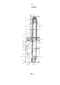
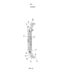
На Фиг.1 схематично показан вид сбоку первой духовки,Figure 1 schematically shows a side view of the first oven,
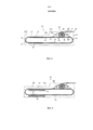
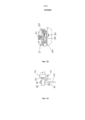
На Фиг.2 схематично показан вид сбоку второй духовки,Figure 2 schematically shows a side view of a second oven,
На Фиг.3 схематично показан вид сбоку третьей духовки,Figure 3 schematically shows a side view of a third oven,
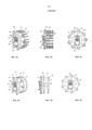
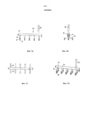
На Фиг.4a-4c показана первая поворотная конструкция,4a-4c show a first pivot structure,
На Фиг.5a-5c показана вторая поворотная конструкция,5a-5c show a second rotary structure,
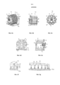
На Фиг.6a-6g показана третья поворотная конструкция,6a-6g show a third rotary structure,
На Фиг.7a-7c показан рычаг для переноски изделия,7a-7c show a handle for carrying an article,
На Фиг.8a-8c показана другая поворотная конструкция,On figa-8c shows another rotary structure,
На Фиг.9a-9d показан первый элемент для выемки изделия иOn figa-9d shows the first element for removing the product and
На Фиг.10a-10d показан второй элемент для выемки изделия,On figa-10d shows a second element for removing the product,
На Фиг.11 показан вид в плане части цепи вафельниц,11 shows a plan view of part of a chain of waffle irons,
На Фиг.12 показан вид вафельницы, наблюдаемый в направлении перемещения вафельниц,On Fig shows a view of the waffle iron observed in the direction of movement of the waffle irons,
На Фиг.13 показан вид сбоку согласно стрелке XIII на Фиг.11 иOn Fig shows a side view according to arrow XIII in Fig.11 and
На Фиг.14 показана деталь.On Fig shows a detail.
На Фиг.1 схематично показан вид сбоку первой духовки 1. Духовка 1 имеет переднюю часть 1a, заднюю часть 1b, корпус 1d, снабженный наружной теплоизоляцией 1c, дополнительно, пекарную камеру 2, расположенную внутри теплоизоляции, и бесконечную цепь 3 вафельниц, непрерывно циркулирующую в духовке 1 и перемещающуюся через пекарную камеру 2. Бесконечная цепь 3 вафельниц расположена в духовке 1 на замкнутой орбите, которая продолжается в двух транспортных уровнях 4 и 5, расположенных один над другим через обе части 1a и 1b духовки. Цепь 3 вафельниц приводится в действие приводным колесом 6, расположенным близко к переднему концу духовки 1, и отклоняется приводным колесом 6 от нижнего транспортировочного уровня 5 вверх на верхний транспортировочный уровень 4. Циркулирующая цепь 3 перемещается в верхнем транспортировочном уровне 4 от приводного колеса 6 в духовке по направлению к задней части. Близко к заднему концу духовки 1 цепь 3 вафельниц проходит заднее отклоняющее устройство 7. У отклоняющего устройства 7 цепь 3 вафельниц отклоняется от верхнего транспортировочного уровня 4 вниз на нижний транспортировочный уровень 5.1 schematically shows a side view of the
Цепь 3 вафельниц содержит открываемые и закрываемые вафельницы 8. Вафельницы 8 расположены одна за другой в цепи 3 вафельниц. В вафельницах 8 находятся формы для выпечки, состоящие из верхних частей и нижних частей, которые открываются при открывании вафельниц 8 и закрываются при закрывании вафельниц 8. Каждая вафельница 8 состоит из нижней части 8a и верхней части 8b, шарнирно соединяемой с упомянутой нижней частью. К верхней части 8b прикреплен управляющий ролик 8c, посредством которого вафельница 8 открывается и закрывается. Плоские пластины для выпечки расположены в нижних частях 8a вафельниц, которые содержат нижние части форм для выпечки. Плоские пластины для выпечки расположены в верхних частях 8b вафельниц, которые содержат верхние части форм для выпечки.The
С передних сторон вафельницы снабжены блокирующими устройствами, не показанными на чертежах, которые приводятся в действие, когда вафельницы закрыты, чтобы удерживать формы для выпечки, расположенные в закрытых вафельницах, закрытыми в течение всего процесса выпекания.On the front sides, the waffle makers are equipped with locking devices, not shown in the drawings, which are activated when the waffle makers are closed, in order to keep the baking dish located in the closed waffle makers closed during the entire baking process.
Духовка 1 снабжена электрическим индукционным нагревателем. Нагреватель имеет генератор 9 переменного тока, расположенный у передней части 1a духовки, и вытянутые индукторы 10, 11, расположенные в пекарной камере 2. Генератор 9 переменного тока соединяется с индукторами 10, 11 по токопроводящим линиям 12, 13 для снабжения индукторов током. Вытянутые индукторы 10, 11 расположены в пекарной камере 2 над и под орбитой цепи 3 вафельниц. Плоские пластины для выпечки, содержащиеся в вафельницах 8, выполнены в виде чувствительных пластин, которые индукционно нагреваются бесконтактным способом магнитными полями, генерируемыми индукторами 10, 11.
Нижнее исполнительное устройство 18 для разблокировки блокирующего устройства вафельниц 8 расположено в передней части 1a духовки на нижнем транспортировочном уровне 5.The
В передней части 1a духовки предусмотрена система 14 рычагов для зацепления с управляющими роликами 8 с вафельниц 8 по верхнему транспортировочному уровню 4. Система 14 рычагов предусматривает три последовательных участка в направлении перемещения вафельниц 8. Система 14 рычагов предусматривает постепенно поднимающийся участок 14a, который образует устройство для открывания вафельниц 8. Участок 14a системы рычагов примыкает к верхнему горизонтальному участку 14b. Это удерживает открытые вафельницы 8 в открытом положении, когда они перемещаются мимо разгрузочной станции 15 духовки 1 и загрузочной станции 16, примыкающей к ней. Участок 14b системы рычагов примыкает к постепенно опускающемуся участку 14c, который образует устройство для закрывания вафельниц 8. На конце системы 14 рычагов расположено верхнее исполнительное устройство 9 для блокировки блокирующих устройств вафельниц 8.In front of the oven 1a, a lever system 14 is provided for engaging with
В разгрузочной станции 15 имеется устройство 17 для выемки изделий, которое выступает в открытые вафельницы 8, и лишь схематично показано на Фиг.1. Устройство 17 для выемки изделий вынимает выпеченные изделия из нижних частей 8a открытых вафельниц 8 и перемещает их на верхнее транспортировочное устройство, не показанное на Фиг.1, посредством которого выпеченные изделия выгружаются из духовки 1.In the unloading station 15 there is a device 17 for the extraction of products, which protrudes into
Во время работы духовки 1 заготовка для выпечки отдельными порциями теста вводится в циркулирующие открытые вафельницы 8 в загрузочной станции 16. Из загрузочной станции 16 вафельницы 8 с управляющими роликами 8c перемещаются по постепенно опускающемуся участку 14с системы рычагов. В то же время верхние части 8b складываются вниз к нижним частям 8a, и вафельницы 8 закрываются. Во время закрывания вафельниц 8 формы для выпечки, содержащиеся в вафельницах 8, закрываются, и порции теста вкладываются в закрытые формы для выпечки. После закрывания вафельниц 8 блокирующие устройства вафельниц 8 приводятся в действие нижним исполнительным устройством 19, и закрытые вафельницы блокируются. Закрытые и блокированные вафельницы 8 доставляются циркулирующей цепью 3 вафельниц через пекарную камеру 2. В пекарной камере 2 формы для выпечки индуктивно нагреваются бесконтактным способом, и порции теста, вложенные в формы для выпечки, выпекаются. Закрытые и блокированные вафельницы 8 с содержащимися в них порциями теста доставляются циркулирующей цепью 3 с вафельницами в нижний транспортировочный уровень 5 в духовке 1 вперед к приводному колесу 6. При прохождении нижнего исполнительного устройства 18 блокирующие устройства вафельниц 8 приводятся в действие нижним исполнительным устройством 18, и закрытые вафельницы 8 разблокировываются. Закрытые и разблокированные вафельницы 8 доставляются по приводному колесу 6 в верхний транспортировочный уровень 4. В верхнем транспортировочном уровне вафельницы 8 с управляющими роликами 8c перемещаются по постепенно поднимающемуся участку 14a системы рычагов. В то же время вафельницы 8 открываются, и верхняя часть 8b вафельницы откидывается. Выпеченные порции теста или выпеченные изделия остаются в нижней части 8a открытых вафельниц 8. В разгрузочной станции 15 выпеченные изделия вынимаются из нижних частей 8а открытых вафельниц 8 устройством 17 для выемки изделий.During the operation of the
На Фиг.2 схематично показан вид сбоку второй духовки 20. Духовка 20 имеет переднюю часть 20a, заднюю часть 20b, корпус, снабженный наружной теплоизоляцией 20c, пекарную камеру 21, расположенную внутри теплоизоляции 20c, и бесконечную цепь 22 вафельниц, непрерывно циркулирующую в духовке 20 и перемещающуюся через пекарную камеру 21. Цепь 22 вафельниц расположена на замкнутой орбите в духовке 20 и продолжается в двух транспортных уровнях 23 и 24, расположенных один над другим через обе части 20a и 20b духовки. Цепь 22 вафельниц приводится в действие приводным колесом, не показанным на Фиг.2, расположенным около переднего конца 25 духовки 20, и отклоняется приводным колесом от нижнего транспортировочного уровня 24 вверх на верхний транспортировочный уровень 23. Циркулирующая цепь 22 перемещается в верхнем транспортировочном уровне 23 от переднего конца 25 духовки 20 назад по направлению к заднему концу 26 духовки 20. Цепь 22 вафельниц около заднего конца 26 духовки 20 отклоняется задним отклоняющим устройством 27 с верхнего транспортировочного уровня 23 вниз на нижний транспортировочный уровень 24.Figure 2 schematically shows a side view of the
Цепь 22 вафельниц содержит открываемые и закрываемые вафельницы 28, в которых находятся формы для выпечки, состоящие из верхних частей и нижних частей, эти формы для выпечки открываются при открывании вафельниц 28 и закрываются при закрывании вафельниц 28. Каждая вафельница 28 имеет нижнюю часть 28a и верхнюю часть 28b, которая шарнирно соединяется с упомянутой нижней частью. К верхней части 28b прикреплен управляющий ролик, не показан на Фиг.2, посредством которого вафельницы 28 открываются и закрываются. Плоские пластины для выпечки расположены в нижних частях 28a вафельниц, которые содержат нижние части форм для выпечки. Плоские пластины для выпечки расположены в верхних частях 28b вафельниц, которые содержат верхние части форм для выпечки.The
Пекарная камера 21 расположена в задней части духовки 20b. Духовка 20 снабжена электрическим индукционным нагревателем, который включает в себя вытянутые индукторы 29, 30, расположенные над и под орбитой вафельниц 28 в двух транспортировочных уровнях 23 и 24.A baking
В передней части 20a духовки 20 друг за другом расположены устройство 31 для открывания вафельниц 28, разгрузочная станция 32, загрузочная станция 33 и устройство 34 для закрывания вафельниц 28 в направлении перемещения вафельниц 28 по верхнему транспортировочному уровню 23. Устройство 35 для выемки изделия, имеющее горизонтально расположенную поворотную конструкцию 36, находится в разгрузочной станции 32. Поворотная конструкция 36 поворачивается вокруг горизонтально расположенной центральной оси и вынимает выпеченные изделия из открытых вафельниц 28a и доставляет их в верхнее транспортировочное устройство 37, которое доставляет выпеченные изделия из духовки 20.A
На Фиг.3 схематично показан вид сбоку третьей духовки 40. Духовка 40 имеет переднюю часть 40a, заднюю часть 40b, корпус, снабженный наружной теплоизоляцией 40c, пекарную камеру 41, расположенную внутри теплоизоляции 40c в задней части 40b духовки, и бесконечную цепь 42 вафельниц, непрерывно циркулирующую в духовке 4 0 и перемещающуюся через пекарную камеру 41. Конструкция духовки 40 соответствует конструкции духовки 20 на Фиг.2 и отличается только нагревом пекарной камеры, который выполнен в виде нагрева 43 газом в духовке 40. Нагрев 43 газом включает в себя вытянутые газовые горелки 44 и 45, которые расположены в пекарной камере 41 под орбитой цепи 42 вафельниц.Figure 3 schematically shows a side view of the
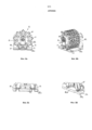
На Фиг.4a-4c показан первый вариант горизонтально расположенной поворотной конструкции устройства для выемки изделий. На Фиг.4a показана косая проекция поворотной конструкции 50 с задней стороны. На Фиг.4b показана поворотная конструкция 50 в рабочем положении. На Фиг.4 с показан вид сзади поворотной конструкции 50.Figures 4a-4c show a first embodiment of a horizontally positioned pivot structure of a product extraction device. Fig. 4a shows an oblique projection of the pivoting
Поворотная конструкция 50 с задней стороны установлена с возможностью поворота в держателе 51, прикрепленном к каркасу духовки. Держатель 51 прикреплен к каркасу духовки с регулировкой по высоте. Поворотная конструкция 50 имеет горизонтально расположенный полый вал 52. Задняя ведущая звезда 53 поворотной конструкции 50 сидит на полом валу 52, упомянутая звезда имеет рычаги 54, расположенные в виде звезды, которые несут на конечных участках установленные с возможностью поворота ведущие ролики 55, которые входят в промежутки между последовательными вафельницами циркулирующей цепи вафельниц.The pivoting
Вертикально расположенная поворотная звезда 56 прикреплена к переднему концу полого вала 52. Поворотная звезда выполнена в виде полого тела. Внутренняя часть поворотной звезды 56 соединена с полой камерой полого вала 52. Внешняя окружность поворотной звезды 56 выполнена в виде многоугольника. Соответственно, два смежных продольных стержня 58 параллельных полому валу 52 прикреплены к прямым сегментам 57 многоугольника. Продольные стержни 58 выполнены в виде полых профилей и каждый несет три элемента 59 для выемки, расположенные на расстоянии друг от друга. Каждый элемент 59 для выемки выполнен в виде всасывающего элемента и соединен с источником вакуума посредством всасывающего трубопровода. Всасывающий трубопровод тянется внутри поворотной конструкции 50 от элемента 59 для выемки через полый продольный стержень 58 и полую поворотную звезду 56 к полому валу 52 и через полый вал 52 наружу из поворотной конструкции 50. Элементы 59 для выемки, прикрепленные к продольным стержням 58, выполнены в виде вакуум-присосов, снабженных эластичными воздуходувными мехами.A vertically located pivoting
Два продольных стержня 58, прикрепленные к прямому сегменту 57 внешней окружности на поворотной звезде 56, расположены в опорной плоскости параллельной оси вращения поворотной конструкции 50. Вакуум-присосы, прикрепленные к двум продольным стержням 58 и снабженные эластичными воздуходувными мехами, расположены перпендикулярно опорной плоскости. Два продольных стержня 58 вместе образуют рычаг поворотной конструкции 50 для переноски изделия. Поворотная конструкция 50 имеет девять таких рычагов для переноски изделий, которые расположены по окружности поворотной конструкции 50 на расстоянии друг от друга.Two
На фиг.5a-5c показан второй вариант горизонтально расположенной поворотной конструкции устройства для выемки изделий. На фиг.5a показана косая проекция поворотной конструкции 60 с задней стороны. На Фиг.5b показана поворотная конструкция 60 в рабочем положении. На фиг.5c показана задняя сторона поворотной конструкции 60.Figures 5a-5c show a second embodiment of a horizontally positioned pivot structure of a product extraction device. Fig. 5a shows an oblique projection of the
Поворотная конструкция 60 установлена с возможностью поворота в держателе 61, прикрепленном к каркасу духовки. Держатель 61 прикреплен к каркасу духовки с регулировкой по высоте. Поворотная конструкция 60 имеет горизонтально расположенный полый вал 62. Задняя ведущая звезда 63 поворотной конструкции 60 сидит на полом валу 62, упомянутая звезда имеет рычаги 64, расположенные в виде звезды, которые несут на конечных участках установленные с возможностью вращения ведущие ролики, которые входят в промежутки между последовательными вафельницами циркулирующей цепи вафельниц.The pivoting
Поворотная конструкция 60 имеет две вертикально расположенные поворотные звезды 66, выполненные в виде полых тел, внутренняя часть которых соединена с полостью полого вала 62. Внешняя окружность поворотных звезд 66 выполнена в виде многоугольника. Соответственно, два элемента 68 для выемки, расположенные на расстоянии друг от друга, прикреплены к каждому прямому сегменту 67 многоугольника, которые выполнены в виде вакуум-присосов, снабженных эластичными воздуходувными мехами, и которые присоединены к источнику вакуума полыми поворотными звездами 66.The
На Фиг.6a-6g показан третий вариант горизонтально расположенной поворотной конструкции устройства для выемки изделий. На Фиг.6a показана косая проекция с задней стороны поворотной конструкции 70, которая выступает в открытые вафельницы духовки. На Фиг.6b показана поворотная конструкция 70 в рабочем положении без вафельниц. На Фиг.6c показана задняя сторона поворотной конструкции 70. На Фиг.6e показано вертикальное сечение поворотной конструкции 70, выступающей в открытые вафельницы духовки перпендикулярно оси вращения поворотной конструкции 70. На Фиг.6e показано вертикальное сечение по оси вращения поворотной конструкции 70, которая выступает в открытые вафельницы духовки. На Фиг.6f показано вертикальное сечение рычага для переноски изделия поворотной конструкции 70 в открытой вафельнице над нижней частью вафельницы. На Фиг.6g показан вид сбоку Фиг.6f.Figures 6a-6g show a third embodiment of a horizontally positioned pivot structure of a product extraction device. Fig. 6a shows an oblique projection from the rear side of the
Поворотная конструкция 70, показанная на Фиг.6a, выступает в три последовательные открытые вафельницы 71 духовки. На Фиг.6a, открытые вафельницы 71 показаны лишь схематично. Поворотная конструкция 70 расположена в открытых вафельницах 71 над нижними частями 71a вафельницы и продолжается передней стороной близко к вверх-сложенным верхним частям 71b вафельницы. Поворотная конструкция 70 установлена с возможностью поворота в держателе 72, прикрепленном к каркасу духовки. Держатель 72 прикреплен к каркасу духовки с регулировкой по высоте. Поворотная конструкция 70 имеет короткий горизонтальный полый вал 73. Ведущая звезда 74, расположенная на задней стороне поворотной конструкции 70, сидит на полом валу 73, упомянутая звезда имеет рычаги 75, расположенные в виде звезды, которые несут ведущие ролики, установленные с возможностью вращения на конечных участках, которые входят в промежутки между последовательными вафельницами 71 циркулирующей цепи вафельниц.The pivoting
Поворотная конструкция 70 включает в себя рычаги 77 для переноски изделий, смежные внешней окружности, которые расположены на расстоянии друг от друга в круговом направлении поворотной конструкции 70, и которые несут элементы 78 поворотной конструкции 70 для выемки, каждый элемент для выемки выполнен в виде всасывающего элемента, расположенного по внешней окружности поворотной конструкции 70.The pivoting
Каждый рычаг 77 для переноски изделий имеет продольный стержень 79, параллельный оси вращения поворотной конструкции 70. На стороне продольного стержня 79, направленной радиально наружу в поворотной конструкции 70, расположено пять поперечных стержней 80, которые соединяются с продольным стержнем 79 радиально расположенным соединительным стержнем 81. Каждый поперечный стержень 80 несет три элемента 78 для выемки, расположенные на расстоянии друг от друга на стороне, направленной радиально наружу в поворотной конструкции 70. Каждый элемент 7 8 для выемки выполнен в виде вакуум-присоса, снабженного эластичными воздуходувными мехами, который прикреплен к поперечному стержню 80. Продольный стержень 79, пять поперечных стержней 80 и пять соединительных стержней 81 выполнены в виде полых профилей. Продольный стержень 79 посредством радиальной соединительной трубы 82, расположенной близко к ведущей звезде 74, соединяется с распределителем 83 вакуума, расположенного на конце полого вала 73,. Рычаг 77 для переноски изделия несет пятнадцать элементов 7 8 для выемки, выполненных в виде вакуум-присосов, которые расположены в плоскости параллельной оси вращения поворотной конструкции 70. Пятнадцать вакуум-присосов соединяются с распределителем 83 отрицательного давления посредством всасывающих трубопроводов, проводимых в рычаге 77 для переноски изделия. Всасывающие трубопроводы тянутся по полым поперечным стержням 80 и полым соединительным стержням 81 к полому продольному стержню 79 и по радиальной соединительной трубе 79 и по радиальной соединительной трубе 82 к распределителю 83 вакуума.Each
Поворотная конструкция 70 имеет девять рычагов 77 для переноски изделия, расположенных на расстоянии друг от друга в окружном направлении поворотной конструкции 70. Поворотная конструкция 70 вращается вокруг горизонтальной оси вращения. В области нижней вершины поворотной конструкции 70, рычаги 77 для переноски изделия один за другим помещаются с вакуум-присосами, снабженными эластичными воздуходувными мехами, благодаря повороту поворотной конструкции 70, на выпеченные изделия, которые находятся на нижних частях 71a открытых вафельниц 71, которые перемещаются через нижнюю вершину поворотной конструкции 70.The
На Фиг.7a-7d показан рычаг 77 для переноски изделия поворотной конструкции 70. На Фиг.7a показан вид сбоку рычага 77 для переноски изделия, на Фиг.7b показан вид спереди рычага 77 для переноски изделия, на Фиг.7с показан вид сверху рычага 77 для переноски изделия, и на Фиг.7d показана косая проекция рычага 77 для переноски изделия.Figures 7a-7d show a
На Фиг.8a-8d показан другой вариант поворотной конструкции устройства для выемки изделия в зацеплении с циркулирующей цепью вафельниц духовки. На Фиг.8a показаны три последовательные открытые вафельницы цепи вафельниц с поворотной конструкцией, выступающей в открытые вафельницы с задней стороны. На Фиг.8b показана косая проекция Фиг.8a. На Фиг.8с показано зацепление поворотной конструкции в цепи вафельниц. На Фиг.8d показана косая проекция Фиг.8c.On figa-8d shows another variant of the rotary structure of the device for removing the product in meshing with the circulating chain of oven waffle irons. Fig. 8a shows three consecutive open waffle irons of a chain of waffle irons with a rotatable structure protruding into the open waffle irons from the rear side. Fig. 8b shows an oblique projection of Fig. 8a. On figs shows the engagement of the rotary structure in the chain of waffle irons. Fig. 8d shows an oblique projection of Fig. 8c.
Поворотная конструкция 85, представленная на Фиг.8a и 8b, выступает в три последовательные открытые вафельницы 86 бесконечной цепи вафельниц духовки. На Фиг.8a и 8b открытые вафельницы 86 показаны лишь схематично. Поворотная конструкция 85 расположена в открытых вафельницах 86 над нижними частями 86a и продолжается передней стороной близко к вверх-сложенным верхним частям 86b вафельницы. Поворотная конструкция 85 установлена с возможностью поворота на задней стороне в держателе 87, прикрепленном к каркасу духовки. Держатель 87 закрепляется на каркасе духовки с возможностью регулировки по высоте. Поворотная конструкция 85 имеет ведущую звезду 88, расположенную на задней стороне поворотной конструкции 85, которая имеет рычаги 89, расположенные в виде звезды, которые несут установленные на конечных участках с возможностью вращения ведущие ролики, которые входят в промежутки, расположенные в цепи вафельниц между нижними частями 86a вафельниц 86. В вафельницах 86 нижние части 86a вафельниц 86 снабжены на передних и задних краях полосками 91, 92, выступающими за пределы нижних частей 86a, к которым примыкают ведущие ролики 90 поворотной конструкции 85.The pivoting
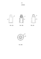
На Фиг.9a-9d показан элемент для выемки изделия поворотной конструкции, который выполнен в виде всасывающей эластично сжимающейся втулки. На Фиг.9a показан вид сбоку всасывающей втулки, на Фиг.9b показано вертикальное сечение всасывающей втулки, на Фиг.9c показана косая проекция всасывающей втулки и на Фиг.9d показан вид в плане всасывающей втулки. Всасывающая втулка 94 имеет два коаксиальных отрезка 94a и 94b трубы, которые могут телескопически входить друг в друга, и сжимающую пружину 95, которая разводит в разные стороны два отрезка 94a и 94b трубы внутри всасывающей втулки 94. Внутренний отрезок 94b трубы несет всасывающую пластину 96, расположенную на свободном конце всасывающей втулки 94.On figa-9d shows the element for the extraction of the product of the rotary structure, which is made in the form of a suction elastically compressible sleeve. Fig. 9a shows a side view of the suction sleeve, Fig. 9b shows a vertical section of the suction sleeve, Fig. 9c shows an oblique projection of the suction sleeve, and Fig. 9d shows a plan view of the suction sleeve. The
На Фиг.10a и 10d показан элемент для выемки изделия поворотной конструкции, который выполнен в виде вакуум-присоса 97, снабженного эластичными воздуходувными мехами 96. На Фиг.10a показан вид сбоку вакуум-присоса, на Фиг.10b показано вертикальное сечение вакуум-присоса, на Фиг.10с показана косая проекция вакуум-присоса, на Фиг.10d показан вид в плане вакуум-присоса.Figures 10a and 10d show an element for removing a product of a rotatable structure, which is made in the form of a
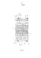
На Фиг.11-14 представлена предпочтительная конструкция для поперечного направления каретки вафельницы. Из предшествующего уровня техники известно направлять ходовые колеса каретки вафельницы ребордой колеса по ходовым рельсам. Это приводило к еще большему износу ходовых подшипников ходовых колес и реборд колес. Конструкция, показанная на Фиг.11-14 устраняет описанные недостатки и продлевает стабильность.11-14 show a preferred design for the transverse direction of the waffle iron carriage. From the prior art it is known to guide the running wheels of a waffle iron carriage by the flange of the wheel along the running rails. This led to even greater wear of the running bearings of the running wheels and the flange of the wheels. The design shown in FIGS. 11-14 eliminates the described disadvantages and prolongs stability.
На Фиг.11 показан вид в плане части устройства двух последовательно расположенных вафельниц 8 по цепи 3 вафельниц. Для более подходящего и с меньшим износом направления каретки вафельницы предусмотрены поперечно расположенные ходовые подшипники 98, которые установлены на вертикальных осях 99 и которые поперечно направляют вафельницы по гребням 100 трака. Оси 99 сидят на принимающих панелях 101, и точное расположение ходового подшипника 98 на угловом носителе 102 можно регулировать регулировочным винтом или регулировочной пластиной. Направление через гребни 100 трака можно регулировать с помощью регулировочного зазора, как показано на Фиг.14.11 shows a plan view of a part of the device of two successively arranged
Гребни 100 трака могут быть выполнены короче или длиннее в продольном продолжении и конкретно приспособлены к скорости перемещения печи для выпечки вафель. Количество продольно расположенных ходовых подшипников 98 можно также увеличить, чтобы обеспечить более точное поперечное направление. Например, на участке перед отклонением каретки вафельницы, количество поперечных направляющих и, следовательно, количество ходовых подшипников 98 можно увеличить, чтобы обеспечить отклонение без проблем.The
Иначе, чем в уже известных ходовых роликах с ребордами колеса, шарикоподшипники ходовых роликов 104, движущихся по рельсам 105, нагружены лишь радиально, в результате чего срок службы увеличивается. Ходовые подшипники можно заменить в случае повреждения.Other than in the already known running rollers with wheel flanges, the ball bearings of the running
Другие механические части, показанные на Фиг.11-14, не требуют разъяснений с точки зрения вышеприведенных разъяснений. Из Фиг.12 можно увидеть, что каждая вафельница содержит верхнюю пластину 8b для выпечки и нижнюю пластину 8a для выпечки. Обе пластины для выпечки шарнирно соединены шарниром 103. Открывание и повторное закрывание вафельницы 8 осуществляется через посредство ходового ролика 8c верхней пластины для выпечки, как и в предшествующем уровне техники.Other mechanical parts shown in FIGS. 11-14 do not require explanation from the point of view of the above explanations. From FIG. 12, it can be seen that each waffle iron includes an upper baking plate 8b and a
Из Фиг.11 также можно увидеть, что вафельницы 8, подвешенные одна на другую для образования цепи вафельниц, присоединены друг к другу с помощью соединительных зажимов 104. Длина гребней 100 трака показана полностью в коротком виде. Пунктирные линии указывают на то, что гребни трака можно выполнить достаточно длинными, чтобы они могли почти касаться гребней трака соседних вафельниц.It can also be seen from FIG. 11 that the
Claims (18)
Applications Claiming Priority (3)
| Application Number | Priority Date | Filing Date | Title |
|---|---|---|---|
| ATA672/2011 | 2011-05-11 | ||
| ATA672/2011A AT511403B1 (en) | 2011-05-11 | 2011-05-11 | OVEN |
| PCT/EP2012/058414 WO2012152778A1 (en) | 2011-05-11 | 2012-05-08 | Oven comprising a product removal device |
Publications (2)
| Publication Number | Publication Date |
|---|---|
| RU2013154374A RU2013154374A (en) | 2015-06-27 |
| RU2591978C2 true RU2591978C2 (en) | 2016-07-20 |
Family
ID=46046206
Family Applications (1)
| Application Number | Title | Priority Date | Filing Date |
|---|---|---|---|
| RU2013154374/13A RU2591978C2 (en) | 2011-05-11 | 2012-05-08 | Oven |
Country Status (7)
| Country | Link |
|---|---|
| US (1) | US9854812B2 (en) |
| EP (1) | EP2706860B1 (en) |
| JP (1) | JP2014513974A (en) |
| AT (1) | AT511403B1 (en) |
| BR (1) | BR112013028727B1 (en) |
| RU (1) | RU2591978C2 (en) |
| WO (1) | WO2012152778A1 (en) |
Cited By (1)
| Publication number | Priority date | Publication date | Assignee | Title |
|---|---|---|---|---|
| RU2725199C1 (en) * | 2016-10-04 | 2020-06-30 | Хаас Фуд Экуипмент ГмбХ | Oven with modular heating element |
Families Citing this family (12)
| Publication number | Priority date | Publication date | Assignee | Title |
|---|---|---|---|---|
| AT513949B1 (en) * | 2013-01-18 | 2015-10-15 | Haas Food Equipment Gmbh | baking device |
| AT514376B1 (en) * | 2013-06-10 | 2016-12-15 | Haas Food Equipment Gmbh | Process and apparatus for producing waffle moldings baked under pressure |
| AT515383B1 (en) * | 2014-01-17 | 2016-02-15 | Haas Food Equipment Gmbh | Baking device and removal device |
| AT515106B1 (en) * | 2014-04-29 | 2015-06-15 | Haas Food Equipment Gmbh | oven |
| CN104686601A (en) * | 2015-02-12 | 2015-06-10 | 洛阳市同圆电子有限公司 | Automatic cake baking machine |
| EP3266307B1 (en) * | 2016-07-06 | 2018-09-26 | Haas Food Equipment GmbH | Baking device |
| CN106417415B (en) * | 2016-10-21 | 2019-01-04 | 河南科技大学 | A kind of cake production equipment |
| ES2682522B1 (en) | 2017-03-20 | 2019-07-29 | Bsh Electrodomesticos Espana Sa | DOMESTIC DEVICE DEVICE |
| DE102019110088B4 (en) * | 2019-04-16 | 2021-10-21 | Marion Thiele | Device for the production of baked moldings |
| CN112900314B (en) * | 2021-01-20 | 2022-11-22 | 邳州市景鹏创业投资有限公司 | Service visitor fence group applied to amusement park equipment |
| EP4275499A1 (en) * | 2022-05-11 | 2023-11-15 | Bühler Food Equipment GmbH | Backing plate device, baking apparatus and baking sheet |
| CN115777733B (en) * | 2022-12-06 | 2023-07-18 | 厚德食品股份有限公司 | Honey cake toasts transportation equipment |
Citations (3)
| Publication number | Priority date | Publication date | Assignee | Title |
|---|---|---|---|---|
| US4417508A (en) * | 1981-05-11 | 1983-11-29 | Haas Franz Sen | Wafer baking oven |
| RU2202205C2 (en) * | 1997-07-23 | 2003-04-20 | Франц Хаас Ваффельмашинен-Индустри Акциенгезелльшафт | Horn manufacturing machine |
| AT506418A1 (en) * | 2008-02-12 | 2009-09-15 | Haas Franz Waffel & Keksanlagen Industrie Gmbh | OVEN |
Family Cites Families (15)
| Publication number | Priority date | Publication date | Assignee | Title |
|---|---|---|---|---|
| US1773031A (en) * | 1927-10-03 | 1930-08-12 | John B Crescio | Wafer machine |
| US2868141A (en) * | 1950-08-23 | 1959-01-13 | Nat Biscuit Co | Sandwich machines |
| US3279634A (en) * | 1965-02-11 | 1966-10-18 | Baker Perkins Inc | Transfer apparatus |
| BE791313A (en) * | 1971-12-13 | 1973-05-14 | Baker Perkins Inc | RELEASE EQUIPMENT, ESPECIALLY FOR BAKERY PRODUCTS |
| US4025267A (en) * | 1975-11-04 | 1977-05-24 | John Amato | Continuous molding machine |
| GB2098450B (en) | 1981-05-11 | 1985-06-12 | Haas Franz Sen | Wafer baking oven |
| DE3529770A1 (en) * | 1985-08-20 | 1987-02-26 | Karl Rinderle | Method and device for producing baked goods from a mass of dough with low viscosity |
| DE3941867A1 (en) * | 1989-12-19 | 1991-06-20 | Bosch Gmbh Robert | DEVICE FOR CONVEYING FLAT OBJECTS, IN PARTICULAR FOLDING BOXES |
| JPH04341420A (en) * | 1991-04-25 | 1992-11-27 | Rheon Autom Mach Co Ltd | Vacuum type depanner device |
| HK1043486A2 (en) * | 2001-10-26 | 2002-08-30 | Chun Kong Ian Cheung | Rotisserie oven |
| US7036426B2 (en) * | 2002-06-13 | 2006-05-02 | Chun Kong Ian Cheung | Rotisserie oven |
| JP2004208617A (en) * | 2002-12-30 | 2004-07-29 | Felis Shokai:Kk | Bread-baking furnace |
| US7234744B2 (en) * | 2004-06-30 | 2007-06-26 | Doboy Inc. | Rotatable, squeeze-spread end effector for industrial robot |
| DE202005013663U1 (en) * | 2005-08-30 | 2005-12-15 | Franz Haas Waffel- Und Keksanlagen-Industrie Gmbh | Plant baking dough to form e.g. waffles, includes charging station for scattered material in recirculation path of baking tongs used to mold waffles |
| US8766148B2 (en) * | 2008-02-12 | 2014-07-01 | Franz Haas Waffel- Und Keksanlagen-Industrie Gmbh | Baking oven having inductors and susceptor plates |
-
2011
- 2011-05-11 AT ATA672/2011A patent/AT511403B1/en not_active IP Right Cessation
-
2012
- 2012-05-08 WO PCT/EP2012/058414 patent/WO2012152778A1/en active Application Filing
- 2012-05-08 BR BR112013028727-6A patent/BR112013028727B1/en active IP Right Grant
- 2012-05-08 JP JP2014509705A patent/JP2014513974A/en active Pending
- 2012-05-08 RU RU2013154374/13A patent/RU2591978C2/en active
- 2012-05-08 US US14/116,798 patent/US9854812B2/en not_active Expired - Fee Related
- 2012-05-08 EP EP12719710.1A patent/EP2706860B1/en active Active
Patent Citations (3)
| Publication number | Priority date | Publication date | Assignee | Title |
|---|---|---|---|---|
| US4417508A (en) * | 1981-05-11 | 1983-11-29 | Haas Franz Sen | Wafer baking oven |
| RU2202205C2 (en) * | 1997-07-23 | 2003-04-20 | Франц Хаас Ваффельмашинен-Индустри Акциенгезелльшафт | Horn manufacturing machine |
| AT506418A1 (en) * | 2008-02-12 | 2009-09-15 | Haas Franz Waffel & Keksanlagen Industrie Gmbh | OVEN |
Cited By (1)
| Publication number | Priority date | Publication date | Assignee | Title |
|---|---|---|---|---|
| RU2725199C1 (en) * | 2016-10-04 | 2020-06-30 | Хаас Фуд Экуипмент ГмбХ | Oven with modular heating element |
Also Published As
| Publication number | Publication date |
|---|---|
| AT511403B1 (en) | 2015-10-15 |
| EP2706860B1 (en) | 2018-10-03 |
| CN103648286A (en) | 2014-03-19 |
| JP2014513974A (en) | 2014-06-19 |
| EP2706860A1 (en) | 2014-03-19 |
| RU2013154374A (en) | 2015-06-27 |
| WO2012152778A1 (en) | 2012-11-15 |
| US20140076176A1 (en) | 2014-03-20 |
| BR112013028727B1 (en) | 2019-10-08 |
| AT511403A1 (en) | 2012-11-15 |
| BR112013028727A2 (en) | 2016-08-09 |
| US9854812B2 (en) | 2018-01-02 |
Similar Documents
| Publication | Publication Date | Title |
|---|---|---|
| RU2591978C2 (en) | Oven | |
| RU2592120C2 (en) | Oven | |
| CA2521455C (en) | Forming and cooking with controlled curtain spillage | |
| JP7376258B2 (en) | Noria device for transporting support plates for bakery products, etc. | |
| JP2011517930A5 (en) | ||
| CN107529765A (en) | The apparatus and method of the bakery for the filling that production and filling make of batter dough | |
| CN111957256A (en) | Processing device and method for instant food | |
| EP1906802B1 (en) | Device for heating food products | |
| US7858130B2 (en) | Automated system for handling food products | |
| US20010013276A1 (en) | Staged rotisserie | |
| US3058434A (en) | Machines for cooking crumpets and like hotplate goods | |
| JP5366049B2 (en) | Automatic baked confectionery manufacturing equipment | |
| EP1059034A1 (en) | Device for subjecting dough pieces and baking products to more than one dough treatment. | |
| WO2020150576A2 (en) | Food preparation apparatus, system, and method | |
| US1764550A (en) | Feeding apparatus for bakers' ovens | |
| JP3201840U (en) | Spherical food production equipment | |
| US20080295705A1 (en) | Making baked spring rolls device and methods | |
| WO2016146984A1 (en) | Cooking apparatus | |
| MXPA00009688A (en) | Method and apparatus for preparing food products for further processing |