RU2587652C2 - Method and apparatus for evaluation of structure in signal - Google Patents
Method and apparatus for evaluation of structure in signal Download PDFInfo
- Publication number
- RU2587652C2 RU2587652C2 RU2013126409/08A RU2013126409A RU2587652C2 RU 2587652 C2 RU2587652 C2 RU 2587652C2 RU 2013126409/08 A RU2013126409/08 A RU 2013126409/08A RU 2013126409 A RU2013126409 A RU 2013126409A RU 2587652 C2 RU2587652 C2 RU 2587652C2
- Authority
- RU
- Russia
- Prior art keywords
- signal
- spectrum
- combined
- correlation
- time domain
- Prior art date
Links
- 238000000034 method Methods 0.000 title claims abstract description 46
- 238000011156 evaluation Methods 0.000 title claims description 3
- 238000001228 spectrum Methods 0.000 claims abstract description 125
- 230000000737 periodic effect Effects 0.000 claims abstract description 10
- 238000012545 processing Methods 0.000 claims description 39
- 238000006243 chemical reaction Methods 0.000 claims description 9
- 238000004590 computer program Methods 0.000 claims description 9
- 238000005070 sampling Methods 0.000 claims description 9
- 230000002238 attenuated effect Effects 0.000 claims description 6
- 230000000694 effects Effects 0.000 abstract description 4
- 239000000126 substance Substances 0.000 abstract 1
- 230000006870 function Effects 0.000 description 21
- 238000001514 detection method Methods 0.000 description 15
- 230000006835 compression Effects 0.000 description 11
- 238000007906 compression Methods 0.000 description 11
- 238000010586 diagram Methods 0.000 description 9
- 230000003595 spectral effect Effects 0.000 description 5
- 230000009466 transformation Effects 0.000 description 4
- 238000013459 approach Methods 0.000 description 3
- 238000004364 calculation method Methods 0.000 description 3
- 230000001419 dependent effect Effects 0.000 description 3
- 238000005259 measurement Methods 0.000 description 3
- 230000000593 degrading effect Effects 0.000 description 2
- 238000012952 Resampling Methods 0.000 description 1
- 238000004458 analytical method Methods 0.000 description 1
- 238000005311 autocorrelation function Methods 0.000 description 1
- 230000005540 biological transmission Effects 0.000 description 1
- 238000004422 calculation algorithm Methods 0.000 description 1
- 238000005336 cracking Methods 0.000 description 1
- 238000002592 echocardiography Methods 0.000 description 1
- 238000000605 extraction Methods 0.000 description 1
- 238000012986 modification Methods 0.000 description 1
- 230000004048 modification Effects 0.000 description 1
- 230000003287 optical effect Effects 0.000 description 1
- 238000013139 quantization Methods 0.000 description 1
- 239000007787 solid Substances 0.000 description 1
- 238000010183 spectrum analysis Methods 0.000 description 1
- 238000012731 temporal analysis Methods 0.000 description 1
- 238000000700 time series analysis Methods 0.000 description 1
- 238000012546 transfer Methods 0.000 description 1
Images
Classifications
-
- G—PHYSICS
- G10—MUSICAL INSTRUMENTS; ACOUSTICS
- G10L—SPEECH ANALYSIS TECHNIQUES OR SPEECH SYNTHESIS; SPEECH RECOGNITION; SPEECH OR VOICE PROCESSING TECHNIQUES; SPEECH OR AUDIO CODING OR DECODING
- G10L25/00—Speech or voice analysis techniques not restricted to a single one of groups G10L15/00 - G10L21/00
- G10L25/90—Pitch determination of speech signals
-
- G—PHYSICS
- G10—MUSICAL INSTRUMENTS; ACOUSTICS
- G10L—SPEECH ANALYSIS TECHNIQUES OR SPEECH SYNTHESIS; SPEECH RECOGNITION; SPEECH OR VOICE PROCESSING TECHNIQUES; SPEECH OR AUDIO CODING OR DECODING
- G10L19/00—Speech or audio signals analysis-synthesis techniques for redundancy reduction, e.g. in vocoders; Coding or decoding of speech or audio signals, using source filter models or psychoacoustic analysis
- G10L19/02—Speech or audio signals analysis-synthesis techniques for redundancy reduction, e.g. in vocoders; Coding or decoding of speech or audio signals, using source filter models or psychoacoustic analysis using spectral analysis, e.g. transform vocoders or subband vocoders
-
- G—PHYSICS
- G10—MUSICAL INSTRUMENTS; ACOUSTICS
- G10L—SPEECH ANALYSIS TECHNIQUES OR SPEECH SYNTHESIS; SPEECH RECOGNITION; SPEECH OR VOICE PROCESSING TECHNIQUES; SPEECH OR AUDIO CODING OR DECODING
- G10L19/00—Speech or audio signals analysis-synthesis techniques for redundancy reduction, e.g. in vocoders; Coding or decoding of speech or audio signals, using source filter models or psychoacoustic analysis
- G10L19/04—Speech or audio signals analysis-synthesis techniques for redundancy reduction, e.g. in vocoders; Coding or decoding of speech or audio signals, using source filter models or psychoacoustic analysis using predictive techniques
- G10L19/16—Vocoder architecture
- G10L19/18—Vocoders using multiple modes
Landscapes
- Engineering & Computer Science (AREA)
- Physics & Mathematics (AREA)
- Health & Medical Sciences (AREA)
- Signal Processing (AREA)
- Audiology, Speech & Language Pathology (AREA)
- Human Computer Interaction (AREA)
- Computational Linguistics (AREA)
- Acoustics & Sound (AREA)
- Multimedia (AREA)
- Spectroscopy & Molecular Physics (AREA)
- Compression, Expansion, Code Conversion, And Decoders (AREA)
- Auxiliary Devices For Music (AREA)
- Measurement Of Resistance Or Impedance (AREA)
- Radar Systems Or Details Thereof (AREA)
Abstract
Description
Область техники, к которой относится изобретениеFIELD OF THE INVENTION
Настоящее изобретение относится к способу, соответствующему устройству и соответствующей компьютерной программе для оценки структуры, в частности основного тона и/или основной частоты, в сигнале, имеющем периодическую, квазипериодическую или виртуально периодическую составляющую.The present invention relates to a method, a corresponding device and a corresponding computer program for assessing the structure, in particular the fundamental tone and / or fundamental frequency, in a signal having a periodic, quasiperiodic or virtually periodic component.
Уровень техникиState of the art
Обнаружение основного тона может использоваться для разных приложений, таких как модификация речи, преобразование текста в речь, кодирование речевого сигнала, извлечение музыкальной информации, системы музыкального исполнения, биометрические измерения, астрофизические измерения и т.д. Для обнаружения основного тона подходы, основанные на временной области и частотной области, являются хорошо известными. Подходы, основанные на временной области, могут осуществляться дешево и легко, например, посредством измерения частоты пересечения нуля, как описано в C.H. Chen, Signal Processing Handbook, New York: Dekker, стр. 531, 1988, или посредством вариации автокорреляции посредством использования подобия последовательных периодов основного тона, как описано в R. Bracewell, The Autocorrelation Function, в The Fourier Transform and Its Applications, New York: MacGraw-Hill, стр. 40-45, 1965. Подходы, основанные на частотной области, обычно являются более сложными и включают в себя этапы быстрого преобразования Фурье (FFT), чтобы преобразовывать сигнал временной области в сигнал частотной области, удаления влияния фазы посредством рассмотрения только мощности частотных составляющих, сжатия значений, чтобы уменьшать влияние огибающей спектра, выработки кандидатов основного тона посредством корреляции лежащих в основе гармоник, как, например, суммирование субгармоник, и нахождения кандидата посредством выбора наивысшего пика. Такие способы являются известными, например, из D.J. Hermes, Measurement of pitch by subharmonic summation, in Journal of the Acoustic Society of America, 83, стр. 257-264, 1988. Другая возможность, чтобы получать кандидаты основного тона, является преобразованием сигнала частотной области назад во временную область посредством обратного преобразования Фурье (IFFT). Например, алгоритм обнаружения основного тона, как известно из B.E. Bongart и др., The Frequency Analysis of Time Series for Echos: Cepstrum, Pseudoautocovariants, Cross-Cepstrum and Saphe Cracking, в Proceedings of the Symposium on Time Series Analysis, Chapter 15 стр. 209-243, New York: Wiley, 1963, основывается на спектральном анализе и использует функцию log для сжатия. Если амплитуда используется как операция сжатия, результирующее обратное преобразование является сигналом нулевой фазы. В этом отношении может использоваться автокорреляция, если не применяется никакое сжатие к спектру мощности.Tone detection can be used for various applications, such as speech modification, text to speech encoding, speech coding, music extraction, musical performance systems, biometric measurements, astrophysical measurements, etc. For pitch detection, approaches based on the time domain and the frequency domain are well known. Time-domain based approaches can be implemented cheaply and easily, for example, by measuring the frequency of the zero crossing, as described in C.H. Chen, Signal Processing Handbook, New York: Dekker, p. 531, 1988, or by varying autocorrelation by using the similarity of consecutive pitch periods, as described in R. Bracewell, The Autocorrelation Function, in The Fourier Transform and Its Applications, New York : MacGraw-Hill, pp. 40-45, 1965. Frequency domain based approaches are usually more complex and include the fast Fourier transform (FFT) steps to convert a time domain signal to a frequency domain signal, removing phase effects by considering only the power of the frequency components, with compressing values to reduce the influence of the spectrum envelope, generating the main tone candidates by correlating the underlying harmonics, such as summing the subharmonics, and finding the candidate by choosing the highest peak. Such methods are known, for example, from D.J. Hermes, Measurement of pitch by subharmonic summation, in Journal of the Acoustic Society of America, 83, pp. 257-264, 1988. Another possibility to obtain pitch candidates is to convert the frequency domain signal back to the time domain by the inverse Fourier transform (IFFT). For example, a pitch detection algorithm, as is known from B.E. Bongart et al., The Frequency Analysis of Time Series for Echos: Cepstrum, Pseudoautocovariants, Cross-Cepstrum and Saphe Cracking, in Proceedings of the Symposium on Time Series Analysis, Chapter 15 pp. 209-243, New York: Wiley, 1963, based on spectral analysis and uses the log function for compression. If the amplitude is used as a compression operation, the resulting inverse transform is a zero phase signal. In this regard, autocorrelation can be used if no compression is applied to the power spectrum.
Сильное сжатие, такое как функция log, усиливает влияние шума и формирует неправильные кандидаты основного тона. Малое сжатие, такое как операция взятия абсолютного значения, является слишком низким, чтобы подавлять влияние огибающих спектра, и поэтому вырабатывает неверные кандидаты из более высоких гармоник. Компромисс состоит в применении операции взятия квадратного корня к значениям амплитуды, как используется в кодере гармонической речи, который известен из R. Taori и др., Harmony-1: A Versatile Low Bit Rate Speech Coding System, Nat. Lab. Technical Note 157/97. Способы обнаружения основного тона обеспечиваются, чтобы определять правильный кандидат из множественных кандидатов, однако если кандидаты являются близкими друг к другу, может выбираться неверный кандидат. Дополнительно, если более высокая и/или более низкая октавы основного тона представлены сильно, способами обнаружения основного тона, известными из предшествующего уровня техники, могут выбираться ложные кандидаты.Strong compression, such as the log function, amplifies the influence of noise and generates incorrect pitch candidates. Small compression, such as the operation of taking the absolute value, is too low to suppress the influence of the envelopes of the spectrum, and therefore produces incorrect candidates from higher harmonics. The trade-off is to apply the square root operation to the amplitude values, as used in the harmonic speech encoder, which is known from R. Taori et al., Harmony-1: A Versatile Low Bit Rate Speech Coding System, Nat. Lab. Technical Note 157/97. Tone detection methods are provided to determine the correct candidate from multiple candidates, however, if the candidates are close to each other, the wrong candidate may be selected. Additionally, if the higher and / or lower octaves of the pitch are strongly represented, false candidates may be selected by the methods of detecting the pitch known by the prior art.
Сущность изобретенияSUMMARY OF THE INVENTION
Задачей настоящего изобретения является обеспечение улучшенных способа, устройства и компьютерной программы для более надежной оценки структуры, в частности основного тона и/или основной частоты, в сигнале.The present invention is the provision of an improved method, device and computer program for a more reliable assessment of the structure, in particular the fundamental tone and / or fundamental frequency, in the signal.
В первом аспекте настоящего изобретения способ для оценки структуры, в частности основного тона и/или основной частоты, в сигнале, имеющем периодическую, квазипериодическую или виртуально периодическую составляющую, содержит:In a first aspect of the present invention, a method for evaluating a structure, in particular a fundamental tone and / or fundamental frequency, in a signal having a periodic, quasiperiodic or virtually periodic component, comprises:
преобразование сигнала из временной области в частотную область, чтобы получать спектр сигнала,converting a signal from a time domain to a frequency domain to obtain a signal spectrum,
обработку спектра, чтобы получать спектр нулевой фазы сигнала,spectrum processing to obtain a spectrum of the zero phase of the signal,
преобразование спектра нулевой фазы сигнала во временную область, чтобы получать сигнал корреляции,converting the spectrum of the zero phase of the signal to the time domain in order to receive a correlation signal,
комбинирование спектра и сигнала корреляции в комбинированный спектр, иcombining the spectrum and the correlation signal into a combined spectrum, and
оценку структуры на основе комбинированного спектра.assessment of the structure based on the combined spectrum.
В дополнительном аспекте настоящего изобретения представлено соответствующее устройство, например, содержащее блок обработки для выполнения этапов вышеупомянутого способа.In an additional aspect of the present invention, there is provided a corresponding device, for example, comprising a processing unit for performing steps of the aforementioned method.
В дополнительном аспекте настоящего изобретения представлена соответствующая компьютерная программа, содержащая средство программного кода для побуждения компьютера выполнять этапы предложенного способа, когда упомянутая компьютерная программа выполняется на компьютере.In an additional aspect of the present invention, there is provided an appropriate computer program comprising program code means for causing a computer to perform the steps of the proposed method when said computer program is executed on a computer.
Предпочтительные варианты осуществления изобретения определяются в зависимых пунктах формулы изобретения. Следует понимать, что заявленное устройство и заявленная компьютерная программа имеют аналогичные и/или идентичные предпочтительные варианты осуществления, что и заявленный способ и как определяется в зависимых пунктах формулы изобретения.Preferred embodiments of the invention are defined in the dependent claims. It should be understood that the claimed device and the claimed computer program have similar and / or identical preferred embodiments as the claimed method and as defined in the dependent claims.
Настоящее изобретение основывается на идее, что на дополнительном этапе спектр частотной области комбинируется с его преобразованием временной области, так что результирующий спектр имеет отчетливый пик в местоположении основного тона и сильное ослабление на более высоких и более низких октавах. Этот способ может использоваться, чтобы оценивать основной тон и/или основную частоту сигнала. Так как результирующий спектр имеет просто отчетливый пик в местоположении основного тона и/или основной частоты, основной тон и/или основная частота может легко обнаруживаться с высокой надежностью.The present invention is based on the idea that, in a further step, the frequency-domain spectrum is combined with its time-domain transformation, so that the resulting spectrum has a distinct peak at the pitch location and strong attenuation at higher and lower octaves. This method can be used to estimate the pitch and / or pitch of the signal. Since the resulting spectrum has a distinct peak at the location of the pitch and / or pitch, the pitch and / or pitch can be easily detected with high reliability.
Согласно предпочтительному варианту осуществления этап преобразования сигнала из временной области в частотную область содержит преобразование Фурье, в частности быстрое преобразование Фурье. Это обеспечивает возможность осуществлять преобразование из временной области в частотную область с малым усилием.According to a preferred embodiment, the step of converting the signal from the time domain to the frequency domain comprises a Fourier transform, in particular a fast Fourier transform. This provides the ability to convert from the time domain to the frequency domain with low effort.
Согласно дополнительному варианту осуществления сигнал обрабатывается посредством узкополосного режекторного фильтра DC. Узкополосный режекторный фильтр DC удаляет низкочастотные сигналы, чтобы предотвращать ложное обнаружение.According to a further embodiment, the signal is processed by means of a DC notch filter. A DC notch filter removes low-frequency signals to prevent false detection.
DC фильтрованный сигнал предпочтительно умножается на оконную функцию. Эта оконная операция ограничивает спектр до области, которая содержит, по меньшей мере, два периода основного тона.The DC filtered signal is preferably multiplied by the window function. This window operation limits the spectrum to an area that contains at least two pitch periods.
Согласно дополнительному варианту осуществления спектр сигнала обрабатывается, чтобы получать спектр амплитуды сигнала. Вычисление амплитуды сигнала обеспечивает операцию сжатия, которая является легко реализуемой и дает результатом сигнал нулевой фазы после обратного преобразования.According to a further embodiment, the signal spectrum is processed to obtain a signal amplitude spectrum. The calculation of the signal amplitude provides a compression operation, which is easily implemented and gives a result of a zero phase signal after the inverse transformation.
Согласно дополнительному варианту осуществления спектр сигнала сжимается в сжатый спектр, в частности посредством операции взятия квадратного корня. Альтернативно, функция сжатия может быть функцией корня, в общем использующей, например, 0,6 в качестве показателя степени. Эта операция акцентирует гармоники основного тона и ослабляет влияние огибающих спектра.According to a further embodiment, the signal spectrum is compressed into a compressed spectrum, in particular by the square root operation. Alternatively, the compression function may be a root function generally using, for example, 0.6 as an exponent. This operation emphasizes the harmonics of the fundamental tone and attenuates the influence of the envelopes of the spectrum.
Согласно дополнительному варианту осуществления спектр сигнала подвергается оконной обработке посредством оконной функции, в частности посредством использования правой половины окна Хенинга или других оконных функций, которые имеют аналогичный эффект. Эта оконная операция ослабляет шумовые высокочастотные составляющие.According to a further embodiment, the signal spectrum is subjected to window processing by a window function, in particular by using the right half of a Hanning window or other window functions that have a similar effect. This window operation attenuates the high-frequency noise components.
Согласно дополнительному варианту осуществления преобразование спектра нулевой фазы, в частности сжатого спектра амплитуды сигнала, во временную область содержит обратное преобразование Фурье. Так как фаза спектра, в частности сжатого спектра, является нулевой, должна вычисляться только положительная ось действительной части спектра. Это обеспечивает возможность получать сигнал корреляции, имеющий пики в кратных периода основного тона.According to a further embodiment, converting the spectrum of the zero phase, in particular the compressed spectrum of the signal amplitude, into the time domain comprises an inverse Fourier transform. Since the phase of the spectrum, in particular the compressed spectrum, is zero, only the positive axis of the real part of the spectrum should be calculated. This makes it possible to obtain a correlation signal having peaks in multiples of the pitch period.
Согласно дополнительному предпочтительному варианту осуществления сигналы корреляции ослабляются посредством оконной функции. Эта оконная операция ослабляет влияние огибающей спектра на сигнал корреляции.According to a further preferred embodiment, the correlation signals are attenuated by the window function. This window operation attenuates the influence of the spectral envelope on the correlation signal.
Согласно предпочтительному варианту осуществления комбинирование спектра и сигнала корреляции содержит повторную дискретизацию, по меньшей мере, одного из спектра или сигнала корреляции. Повторная дискретизация обеспечивает возможность комбинировать спектр и сигнал корреляции, имеющий обратно пропорциональные оси. В частности, является предпочтительным использовать логарифмическую шкалу. Это обеспечивает возможность комбинировать спектр и сигнал, имеющий большое различие в разрешении для высоких и низких частот разных областей.According to a preferred embodiment, combining the spectrum and the correlation signal comprises re-sampling at least one of the spectrum or correlation signal. Re-sampling provides the ability to combine the spectrum and the correlation signal, which is inversely proportional to the axis. In particular, it is preferable to use a logarithmic scale. This provides the opportunity to combine the spectrum and the signal, which has a large difference in resolution for high and low frequencies in different areas.
Согласно предпочтительному варианту осуществления оценка структуры содержит поиск абсолютного максимума комбинированного сигнала. Это обеспечивает надежную и простую возможность находить основной тон и/или основную частоту сигнала.According to a preferred embodiment, the structure assessment comprises searching for the absolute maximum of the combined signal. This provides a reliable and easy way to find the fundamental tone and / or fundamental frequency of the signal.
Согласно предпочтительному варианту осуществления сигнал выпрямляется, в частности посредством функции двухполупериодного выпрямления. Это обеспечивает возможность определять основной тон и/или основную частоту сигнала, когда основная частота отсутствует, без ухудшения характеристики для нефильтрованных сигналов.According to a preferred embodiment, the signal is rectified, in particular by means of a half-wave rectification function. This provides the ability to determine the fundamental tone and / or fundamental frequency of the signal when the fundamental frequency is absent, without degrading the performance for unfiltered signals.
Согласно предпочтительному варианту осуществления спектр нулевой фазы выпрямленного сигнала сравнивается со спектром нулевой фазы невыпрямленного сигнала, и при этом максимум этих сигналов выбирается и комбинируется с сигналом корреляции, чтобы формировать комбинированный сигнал. Причина, чтобы брать максимум спектров, состоит в том, что в случае чистых синусоидальных сигналов выпрямление удаляет основную частоту и вырабатывает только более высокие гармоники. Чтобы уменьшать искажение, спектры выпрямленного и невыпрямленного сигнала комбинируются посредством выбора максимума этих спектров.According to a preferred embodiment, the zero-phase spectrum of the rectified signal is compared with the zero-phase spectrum of the non-rectified signal, and the maximum of these signals is selected and combined with the correlation signal to form a combined signal. The reason for taking maximum spectra is that in the case of pure sinusoidal signals, rectification removes the fundamental frequency and produces only higher harmonics. To reduce distortion, the spectra of the rectified and non-rectified signal are combined by selecting the maximum of these spectra.
Краткое описание чертежейBrief Description of the Drawings
Эти и другие аспекты изобретения будут видны из и объяснены со ссылкой на вариант(ы) осуществления, описанный(е) ниже. На следующих чертежах:These and other aspects of the invention will be apparent from and explained with reference to embodiment (s) described below. In the following drawings:
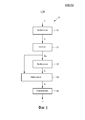
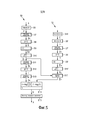
фиг. 1 показывает схематичную диаграмму последовательности операций способа обнаружения основного тона согласно настоящему изобретению,FIG. 1 shows a schematic flowchart of a pitch detection method according to the present invention,
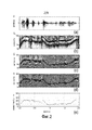
фиг. 2 показывает диаграмму исходного сигнала, подлежащего обработке, и сжатый спектр, сигнал корреляции, комбинированный спектр и измеренный основной тон, выведенный из исходного сигнала посредством способа обнаружения основного тона,FIG. 2 shows a diagram of a source signal to be processed, and a compressed spectrum, a correlation signal, a combined spectrum, and a measured pitch obtained from the source signal by the pitch detection method,
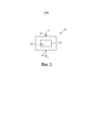
фиг. 3 показывает схематичный чертеж устройства для выполнения обнаружения основного тона согласно настоящему изобретению,FIG. 3 shows a schematic drawing of a device for performing pitch detection according to the present invention,
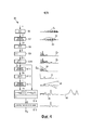
фиг. 4 показывает диаграмму последовательности операций одного варианта осуществления способа для обнаружения основного тона,FIG. 4 shows a flow chart of one embodiment of a method for detecting a pitch,
фиг. 5 показывает диаграмму последовательности операций дополнительного варианта осуществления способа для обнаружения основного тона,FIG. 5 shows a flowchart of a further embodiment of a method for detecting a pitch,
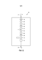
фиг. 6 показывает блок-схему блока обработки, выполняющего способ согласно фиг. 4,FIG. 6 shows a block diagram of a processing unit executing the method of FIG. four,
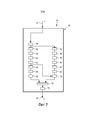
фиг. 7 показывает блок-схему блока обработки, выполняющего способ согласно фиг. 5, иFIG. 7 shows a block diagram of a processing unit executing the method of FIG. 5, and
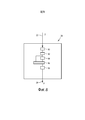
фиг. 8 показывает блок-схему блока обработки, выполняющего способ согласно фиг. 1.FIG. 8 shows a block diagram of a processing unit executing the method of FIG. one.
Подробное описание изобретенияDETAILED DESCRIPTION OF THE INVENTION
Фиг. 1 показывает диаграмму последовательности операций способа для обнаружения основного тона и/или основной частоты сигнала, имеющего периодическую, квазипериодическую или виртуальную периодическую составляющую, в общем обозначаемого посредством 10. Примерами для этих сигналов являются запись голосовой речи, музыкальный тон инструмента, сигналы тела, такие как биение сердца, радиосигналы от звезд, сигналы наблюдения деятельности. Входной сигнал s, который является квазипериодическим или виртуально периодическим сигналом, таким как речевой сигнал, преобразовывается на этапе S1 из сигнала временной области в спектр частотной области. Преобразование предпочтительно содержит быстрое преобразование Фурье (FFT). Этап S1 обеспечивает спектр S сигнала s. Спектр S обрабатывается на этапе S2, чтобы удалять информацию фазы спектра и чтобы получать спектр нулевой фазы (Sm). Обработка содержит вычисление амплитуды спектра S и факультативно спектральное сжатие спектра S, например, посредством операции взятия квадратного корня. Этап S2 обработки и/или сжатия акцентирует гармоники основного тона и ослабляет влияние огибающей спектра. Этап S2 обеспечивает спектр нулевой фазы Sm.FIG. 1 shows a flowchart of a method for detecting a fundamental tone and / or a fundamental frequency of a signal having a periodic, quasiperiodic, or virtual periodic component, generally denoted by 10. Examples of these signals are voice recording, musical instrument tone, body signals such as heartbeat, radio signals from stars, activity observation signals. The input signal s, which is a quasiperiodic or virtually periodic signal, such as a speech signal, is converted in step S1 from a time-domain signal to a frequency-domain spectrum. The transform preferably contains a fast Fourier transform (FFT). Step S1 provides a spectrum S of signal s. The spectrum S is processed in step S2 to remove phase information of the spectrum and to obtain a spectrum of the zero phase (S m ). The processing includes calculating the amplitude of the spectrum S and optionally spectral compression of the spectrum S, for example, by the square root operation. The processing and / or compression step S2 emphasizes the harmonics of the fundamental tone and attenuates the influence of the spectral envelope. Step S2 provides a zero phase spectrum S m .
Спектр нулевой фазы Sm преобразовывается на этапе S3 из частотной области во временную область предпочтительно с использованием обратного преобразования Фурье. Этап S3 преобразования обеспечивает сигнал корреляции c, который содержит пики в кратных периода основного тона.The zero phase spectrum S m is converted in step S3 from the frequency domain to the time domain, preferably using the inverse Fourier transform. The conversion step S3 provides a correlation signal c that contains peaks in multiples of the pitch period.
Спектр нулевой фазы Sm и сигнал корреляции c комбинируются на этапе S4 в комбинированный спектр b. Комбинированный спектр b содержит отчетливый пик на основном тоне, при этом более высокие гармоники в частотном спектре и кратных периода основного тона ослабляются, оставляя основной тон и/или основную частоту как преобладающий пик. Комбинирование S4 выполняется посредством умножения спектра нулевой фазы Sm на сигнал корреляции c.The zero phase spectrum S m and the correlation signal c are combined in step S4 into a combined spectrum b. The combined spectrum b contains a distinct peak at the fundamental tone, while higher harmonics in the frequency spectrum and multiples of the fundamental period are attenuated, leaving the fundamental and / or fundamental as the dominant peak. The combination of S4 is performed by multiplying the spectrum of the zero phase S m by the correlation signal c.
На основе комбинированного спектра b выполняется обнаружение S5 пика, чтобы оценивать основной тон и/или основную частоту сигнала. Обнаружение S5 пика содержит поиск максимума в комбинированном спектре b и обеспечивает выходной сигнал p, который соответствует основному тону и/или основной частоте исходного сигнала s.Based on the combined spectrum b, peak S5 detection is performed to estimate the fundamental tone and / or fundamental frequency of the signal. Detecting the peak S5 comprises searching for a maximum in the combined spectrum b and provides an output signal p that matches the fundamental tone and / or fundamental frequency of the original signal s.
Этап S4 комбинирования спектра нулевой фазы Sm с его преобразованием временной области c дает результатом комбинированный спектр b, который имеет отчетливый пик в местоположении основного тона и/или основной частоты и сильное ослабление на более высоких и более низких октавах. Следовательно, обнаружение пика является надежным, так как местоположение основного тона и/или основная частота соответствуют наивысшему пику в комбинированном спектре b.Step S4 of combining the spectrum of the zero phase S m with its transformation of the time domain c results in a combined spectrum b that has a distinct peak at the location of the pitch and / or pitch and a strong attenuation at higher and lower octaves. Therefore, peak detection is reliable since the pitch location and / or the fundamental frequency correspond to the highest peak in the combined spectrum b.
Фиг. 2 показывает пять диаграмм фиг. 2a-e, показывающих амплитуду исходного сигнала s, частоту сжатого спектра Sc, частоту сигнала корреляции c, частоту комбинированного спектра b и выходной сигнал, основной тон p исходного сигнала s по отношению к времени.FIG. 2 shows five diagrams of FIG. 2a-e, showing the amplitude of the original signal s, the frequency of the compressed spectrum S c , the frequency of the correlation signal c, the frequency of the combined spectrum b and the output signal, the pitch p of the original signal s with respect to time.
Исходный сигнал s, показанный на фиг. 2a, является временной областью английского предложения "do they take the car when they go aboard". Сжатый сигнал Sc, выведенный из исходного сигнала s посредством этапа S1 преобразования и этапа S2 обработки и сжатия, показан на фиг. 2b.The source signal s shown in FIG. 2a, is a temporary area of the English sentence "do they take the car when they go aboard". The compressed signal S c derived from the original signal s by the conversion step S1 and the processing and compression step S2 is shown in FIG. 2b.
Частота сигнала корреляции c, выведенного из сжатого спектра Sc посредством этапа S3 преобразования, показана на фиг. 2C.The frequency of the correlation signal c derived from the compressed spectrum S c by the conversion step S3 is shown in FIG. 2C.
Частота комбинированного спектра b, выведенного из комбинирования сжатого спектра Sc и сигнала корреляции c посредством этапа S4, показана на фиг. 2d.The frequency of the combined spectrum b derived from combining the compressed spectrum S c and the correlation signal c by step S4 is shown in FIG. 2d.
Основной тон p по отношению к времени, выведенный из комбинированного спектра b посредством обнаружения пика из этапа S5, показан на фиг. 2e.The fundamental tone p with respect to time derived from the combined spectrum b by detecting a peak from step S5 is shown in FIG. 2e.
Следовательно, фиг. 2 показывает сигналы или спектры, обеспеченные посредством некоторых этапов S1 по S5 способа, по отношению к времени.Therefore, FIG. 2 shows the signals or spectra provided by some method steps S1 to S5 with respect to time.
Фиг. 3 показывает блок-схему устройства для выполнения обнаружения основного тона, которое, в общем, обозначено посредством 20.FIG. 3 shows a block diagram of a device for performing pitch detection, which is generally indicated by 20.
Устройство 20 содержит вход 22 сигнала и выход 24 сигнала, чтобы принимать исходный сигнал s и обеспечивать выходной сигнал p, соответственно. Устройство 20 содержит блок 26 обработки для обработки входного сигнала s и чтобы оценивать основной тон и/или основную частоту входного сигнала s. Блок 26 обработки обеспечивает выходной сигнал p на выход 24 устройства 20. Блок 26 обработки содержит память 28, чтобы хранить программные коды для побуждения блока 26 обработки выполнять этапы способа для обработки входного сигнала s.The
Блок 26 обработки может осуществляться посредством интегральной схемы или компьютера или может осуществляться посредством дискретных элементов и/или устройств, которые выполняют необходимые этапы обработки.The
Фиг. 4 показывает диаграмму последовательности операций способа обнаружения основного тона, в общем, обозначаемого посредством 30, и соответствующие сигналы или спектры, обеспечиваемые посредством некоторых этапов способа.FIG. 4 shows a flowchart of a method for detecting a pitch, generally indicated by 30, and corresponding signals or spectra provided by some steps of the method.
Исходный сигнал s предпочтительно фильтруется посредством узкополосного режекторного фильтра DC на первом этапе S6. Низкие частоты входного сигнала s могут искажать обработку обнаружения основного тона вследствие этапа оконной обработки перед преобразованием Фурье из временной области в частотную область. Этап оконной обработки размывает (перераспределяет) энергию доминирующего сигнала DC к более высоким частотам и может акцентировать слабые низкие частоты исходного сигнала s. Чтобы предотвращать ложное обнаружение, низкие частоты исходного сигнала s должны удаляться до последующей оконной обработки. Узкополосный режекторный фильтр DC этапа S6 используется, чтобы удалять низкие частоты исходного сигнала s. Узкополосный режекторный фильтр DC согласно S6 содержит передаточную функцию:The source signal s is preferably filtered by a notch filter DC in the first step S6. The low frequencies of the input signal s may distort the pitch detection processing due to the window processing step before the Fourier transform from the time domain to the frequency domain. The window processing step blurs (redistributes) the energy of the dominant DC signal to higher frequencies and may emphasize the weak low frequencies of the original signal s. To prevent false detection, the low frequencies of the original signal s should be removed before subsequent window processing. The DC notch filter of step S6 is used to remove the low frequencies of the original signal s. The S6 notch DC filter according to S6 contains a transfer function:

гдеWhere

fs является частотой дискретизации и fc является обрезающей частотой в Гц, на которой выходная мощность узкополосного режекторного фильтра DC уменьшается до 50% входной мощности (-3 дБ). Реализация фильтра во временной области дается посредством:f s is the sampling frequency and f c is the cutoff frequency in Hz, at which the output power of the DC notch filter is reduced to 50% of the input power (-3 dB). The implementation of the filter in the time domain is given by:
![]()
![]()
содержит исходный сигнал s, DC фильтрованный сигнал sf как выходной сигнал этапа S6 и n как n входной отсчет. Для речевого сигнала, частота дискретизации 8 кГц и обрезающая частота 500 Гц, α приблизительно равняется 0,94. Выходной сигнал узкополосного режекторного фильтра DC sf не содержит низкочастотных составляющих, как показано на фиг. 4.contains the original signal s, the DC filtered signal s f as the output of step S6, and n as the n input sample. For a speech signal, a sampling frequency of 8 kHz and a cutoff frequency of 500 Hz, α is approximately 0.94. The output signal of the notch filter DC s f does not contain low-frequency components, as shown in FIG. four.
Следующий этап S7 является оконной функцией. DC фильтрованный сигнал sf умножается на оконную функцию 32. Оконная функция 32 ослабляет возможные разрывы на границах и ограничивает сигнал областью, которая содержит, по меньшей мере, два периода основного тона. Например, если ожидается, что наименьший основной тон 40 Гц, продолжительность окна должна быть, по меньшей мере, 50 мс. Предпочтительно, используется оконная функция Хенинга:The next step S7 is a window function. The DC filtered signal s f is multiplied by the

Альтернативно может использоваться оконная функция Хемминга или любая другая оконная функция с аналогичными характеристиками. L зависит от частоты дискретизации, при этом L равняется 400 для частоты дискретизации 8 кГц и продолжительности 50 мс.Alternatively, a Hamming window function or any other window function with similar characteristics may be used. L depends on the sampling frequency, with L equal to 400 for a sampling frequency of 8 kHz and a duration of 50 ms.
Оконная операция определяется посредством:Window operation is determined by:

![]()
![]()
где sw является выходным сигналом оконной функции этапа S7. Сигнал sw преобразовывается из временной области в частотную область на этапе S8. Это преобразование содержит дискретное преобразование Фурье (DFT), чтобы обеспечивать спектр S сигнала sw. Функция преобразования дискретного преобразования Фурье задается посредством:where s w is the output of the window function of step S7. The signal s w is converted from the time domain to the frequency domain in step S8. This transform contains a discrete Fourier transform (DFT) to provide a spectrum S of the signal s w . The discrete Fourier transform transform function is defined by:

По причинам эффективности предпочтительно используется FFT по основанию 2. В этом случае размер M преобразования DFT имеет степень 2 и является самым близким к, но не меньшим, чем L. Например, для L, равного 400, M устанавливается на 512.For reasons of efficiency, the base FFT 2 is preferably used. In this case, the size M of the DFT transform is of degree 2 and is the closest to, but not less than L. For example, for L equal to 400, M is set to 512.
На этапе S9 вычисляется спектр амплитуды частотного спектра S. Так как sw является действительно-значным сигналом и S является симметрическим относительно нуля, для вычисления амплитуды используется только положительная ось. Таким образом, формула преобразования Фурье, упомянутая выше, может быть переписана как:In step S9, the amplitude spectrum of the frequency spectrum S is calculated. Since s w is a true-valued signal and S is symmetric with respect to zero, only the positive axis is used to calculate the amplitude. Thus, the Fourier transform formula mentioned above can be rewritten as:

где SR является действительной частью и SI является мнимой частью спектра. Амплитуда вычисляется на этапе S9 посредством формулы:where S R is the real part and S I is the imaginary part of the spectrum. The amplitude is calculated in step S9 by the formula:

где Sm является выходным частотным спектром из этапа S9. На последующем этапе S10 спектр амплитуды Sm сжимается посредством операции взятия квадратного корня:where S m is the output frequency spectrum from step S9. In a subsequent step S10, the amplitude spectrum S m is compressed by the square root operation:


Операция взятия квадратного корня акцентирует гармоники основного тона и ослабляет влияние огибающей спектра, например, как форманты в речевом сигнале. Выходной сигнал сжатия из S10 является сжатым спектром амплитуды Sc.The square root operation emphasizes the harmonics of the fundamental tone and attenuates the influence of the spectral envelope, for example, as formants in a speech signal. The compression output from S10 is a compressed amplitude spectrum S c .
На этапе S11 сжатый спектр амплитуды Sc подвергается оконной обработке в частотной области, чтобы ослаблять шумовые высокочастотные составляющие предпочтительно посредством использования правой половины окна Хенинга:At step S11, the compressed amplitude spectrum S c is subjected to windowing in the frequency domain in order to attenuate the high-frequency noise components, preferably by using the right half of the Hanning window:

гдеWhere


N определяет размер диапазона пропускания. Для речевого сигнала, имеющего частоту дискретизации 8 кГц и диапазон пропускания 2 кГц ![]()
![]()
Подвергнутый оконной обработке сжатый спектр амплитуды Sw преобразовывается на этапе S12 во временную область с использованием обратного преобразования Фурье (IFT). Размер FFT остается, как показано выше:The windowed compressed amplitude spectrum S w is converted in step S12 to the time domain using the inverse Fourier transform (IFT). The FFT size remains as shown above:

Так как фаза подвергнутого оконной обработке сжатого спектра амплитуды Sw равняется нулю, для обратного преобразования необходима только положительная ось действительной части спектра:Since the phase of the windowed compressed spectrum of the amplitude spectrum S w is equal to zero, for the inverse transformation only the positive axis of the real part of the spectrum is needed:

Это преобразование во временную область используется, чтобы получать сигнал корреляции c, который содержит пики в кратных периода основного тона, как показано на фиг. 4.This time domain conversion is used to obtain the correlation signal c, which contains peaks in multiples of the pitch period, as shown in FIG. four.
На этапе S13 сигнал корреляции c подвергается оконной обработке, чтобы дополнительно ослаблять влияние огибающей спектра. Предпочтительно для этого этапа ослабления используется простая оконная функция 36:In step S13, the correlation signal c is subjected to window processing to further attenuate the influence of the spectral envelope. Preferably, a

Выходной сигнал этапа S13 является подвергнутым оконной обработке сигналом корреляции cw.The output of step S13 is a windowed correlation signal c w .
На этапе 14 комбинированный спектр b формируется посредством умножения сжатого спектра амплитуды Sc и ослабленного сигнала корреляции cw. Этот комбинированный спектр b имеет отчетливый пик на основной частоте. Посредством умножения этих спектров, более высокие гармоники в частотных спектрах и кратных периодов основного тона ослабляются, при этом основная частота и/или основной тон остается как преобладающий пик. До комбинирования спектров может использоваться повторная дискретизация, по меньшей мере, одного из спектров, так как оси являются обратно пропорциональными, при этом:At step 14, the combined spectrum b is formed by multiplying the compressed spectrum of the amplitude S c and the attenuated correlation signal c w . This combined spectrum b has a distinct peak at the fundamental frequency. By multiplying these spectra, higher harmonics in the frequency spectra and multiple periods of the fundamental tone are attenuated, while the fundamental frequency and / or fundamental remains as the predominant peak. Before combining the spectra, re-sampling of at least one of the spectra can be used, since the axes are inversely proportional, while:

Из-за различия разрешения для низких и высоких частот между разными областями, комбинирование предпочтительно выполняется посредством использования логарифмической шкалы:Due to the difference in resolution for low and high frequencies between different regions, combining is preferably done by using a logarithmic scale:


где kmin и kmax соответствуют действительному диапазону основного тона. Например, для речи, является обычным диапазон основного тона между 40 и 600 Гц. R определяет размер выходного массива. Является достаточным использовать длину входного окна для R с L=R.where k min and k max correspond to the actual range of the fundamental tone. For example, for speech, the usual pitch range is between 40 and 600 Hz. R determines the size of the output array. It is sufficient to use the input window length for R with L = R.
Операция повторной дискретизации предпочтительно выполняется посредством использования сплайновой интерполяции:The resampling operation is preferably performed by using spline interpolation:

где ![]()
![]()
![]()
![]()
![]()
![]()
Квантованные индексы также как сплайновые коэффициенты могут предварительно вычисляться и сохраняться в массиве, чтобы избегать длительных вычислений для комплексных логарифмических и экспоненциальных операций. Повторно дискретизированные спектры, которые комбинируются на S14, показаны на фиг. 4 и обозначены посредством 38, 40.Quantized indices as well as spline coefficients can be precomputed and stored in an array to avoid lengthy calculations for complex logarithmic and exponential operations. The resampled spectra that are combined in S14 are shown in FIG. 4 and are indicated by 38, 40.
Обнаружение пикового положения как конечный этап S15 содержит поиск максимума комбинированного спектра b:The detection of the peak position as the final step S15 contains the search for the maximum of the combined spectrum b:


где ml является максимумом и pl является положением максимума в масштабированной логарифмической области. Основной тон в линейной области в Гц определяется посредством:where m l is the maximum and p l is the position of the maximum in the scaled logarithmic region. The fundamental tone in the linear region in Hz is determined by:

На фиг. 5 дополнительный вариант осуществления способа для обнаружения основного тона, в общем, обозначен посредством 50. Способ 50 является аналогичным способу 30, показанному на фиг. 4. Идентичные этапы и сигналы обозначаются посредством идентичных ссылочных позиций, при этом подробно описываются только различия.In FIG. 5, an additional embodiment of a method for detecting a fundamental tone is generally indicated by 50.
Способ 50 предпочтительно используется для нахождения основного тона исходного сигнала s, когда основная частота отсутствует. В случаях когда высокочастотные фильтры применяются к сигналу до обнаружения основного тона, например, как в телефонной речи, основная частота теряется. Обеспечивается способ 50, чтобы приводить основную частоту назад без ухудшения характеристики для нефильтрованных сигналов.
Способ 50 содержит отдельный путь 52 для обеспечения выпрямленного спектра DC фильтрованного сигнала sf.The
DC фильтрованный сигнал sf выпрямляется на этапе S16, чтобы обеспечивать выпрямленный сигнал r. Предпочтительно осуществляется двухполупериодное выпрямление DC фильтрованного сигнала sf посредством двухполупериодного выпрямителя. Формула двухполупериодного выпрямителя дается посредством:The DC filtered signal s f is rectified in step S16 to provide a rectified signal r. Preferably, the half-wave rectification of the DC filtered signal s f is effected by means of a half-wave rectifier. The formula for a half-wave rectifier is given by:

За этапом S16 выпрямления следуют этапы S6' по S10', чтобы обеспечивать выпрямленный сжатый спектр амплитуды Rc выпрямленного сигнала. Этапы S6' по S10' являются идентичными этапам S6 по S10, как описано выше. На этапе S17 комбинируются сжатый спектр амплитуды Sc невыпрямленного сигнала sf и выпрямленного сжатого спектра амплитуды Rc. Для уменьшения искажения и для случая, когда выпрямление удаляет основную частоту и вырабатывает только более высокие гармоники, выпрямленный сжатый спектр амплитуды Rc выпрямленного сигнала r и невыпрямленный сигнал s комбинируются, при этом максимум этих спектров выбирается согласно формуле:Rectification step S16 is followed by S6 'to S10' to provide a rectified compressed spectrum of the amplitude R c of the rectified signal. Steps S6 'to S10' are identical to steps S6 to S10, as described above. In step S17, the compressed amplitude spectrum S c of the non-rectified signal s f and the rectified compressed amplitude spectrum R c are combined. To reduce distortion and for the case when rectification removes the fundamental frequency and produces only higher harmonics, the rectified compressed amplitude spectrum R c of the rectified signal r and the non-rectified signal s are combined, and the maximum of these spectra is selected according to the formula:

где d является масштабирующим коэффициентом и предпочтительно устанавливается на 2. Выходной сигнал из S17 является Rc', максимумом сжатого спектра амплитуды выпрямленного сигнала и невыпрямленного сигнала.where d is a scaling factor and is preferably set to 2. The output from S17 is R c ', the maximum of the compressed amplitude spectrum of the rectified signal and the non-rectified signal.
Выходной сигнал из S17 комбинируется с ослабленным сигналом корреляции cw на этапе S14, как описано выше.The output from S17 is combined with the attenuated correlation signal c w in step S14, as described above.
Фиг. 6 показывает блок-схему одного варианта осуществления блока 26 обработки, как показано на фиг. 3. Блок 26 обработки согласно фиг. 6 содержит некоторые дискретные элементы или устройства, которые обеспечиваются, чтобы выполнять этапы способа согласно фиг. 4.FIG. 6 shows a block diagram of one embodiment of a
Вход 22 соединяется с узкополосным режекторным фильтром 54 DC, выполняющим этап S6. Узкополосный режекторный фильтр 54 DC соединен с оконным элементом 56, выполняющим этап S7. Оконный элемент 56 соединен с элементом 58 преобразования Фурье, выполняющим этап S8. Элемент 58 преобразования Фурье соединен с элементом 60 вычисления абсолютного значения, обеспеченным, чтобы вычислять амплитуду согласно этапу S9. Элемент 60 вычисления абсолютного значения соединен с элементом 62 операции взятия корня, который выполняет этап S10. Элемент 62 операции взятия корня соединен с оконным элементом 64, который обеспечивается, чтобы выполнять этап S11. Оконный элемент 64 соединен с элементом 66 обратного преобразования Фурье, который обеспечивается, чтобы выполнять S12. Элемент обратного преобразования Фурье соединен с оконным элементом 68, который обеспечивается, чтобы выполнять S13. Оконный элемент 68 соединен с элементом 70 комбинирования, который обеспечивается, чтобы выполнять S14. Элемент 62 операции взятия корня также соединен с элементом 70 комбинирования, чтобы обеспечивать сжатый спектр амплитуды Sc в элемент 70 комбинирования. Элемент 70 комбинирования соединен с элементом 72 детектора пикового положения, который обеспечивается, чтобы выполнять этап S15. Элемент 72 обнаружения пикового положения соединен с выходом блока 26 обработки, чтобы обеспечивать основной тон p на выход 24.The
Фиг. 7 показывает схематическую блок-схему одного варианта осуществления блока 26 обработки, как показано на фиг. 6. Ссылка делается на фиг. 6, при этом идентичные этапы, элементы и сигналы обозначаются посредством идентичных ссылочных позиций и подробно описываются только различия. Блок 26 обработки согласно фиг. 7 содержит некоторые дискретные элементы или устройства, которые обеспечиваются, чтобы выполнять этапы способа согласно фиг. 5.FIG. 7 shows a schematic block diagram of one embodiment of a
Согласно этому варианту осуществления блок 26 обработки из фиг. 7 содержит дополнительный параллельный путь 74, чтобы обеспечивать выпрямленный сжатый спектр амплитуды исходного сигнала s. Путь 74 выполняет этапы пути 52, показанного на фиг. 5. Путь 74 содержит выпрямитель 76, который соединен с узкополосным режекторным фильтром 54 DC, чтобы выполнять этап S16. Выпрямитель 76 соединен с каскадом элементов 54', 56', 58', 60' и 62', которые являются идентичными элементам 54, 56, 58, 60 и 62, соответственно, чтобы выполнять этапы S6', S7', S8', S9' и S10'. Элементы 62 и 62' операции взятия корня соединены с элементом 78 определения максимума, выполняющим этап S17. Элемент 78 определения максимума соединен с элементом 70 комбинирования, выполняющим этап S14.According to this embodiment, the
Фиг. 8 показывает блок-схему одного варианта осуществления блока 26 обработки, как показано на фиг. 3, чтобы выполнять способ согласно фиг. 1. В общем, блок 26 обработки также называется "устройство" или " система".FIG. 8 shows a block diagram of one embodiment of a
Блок 26 обработки содержит первый блок 80 преобразования, чтобы выполнять этап S1, блок 82 обработки, чтобы выполнять этап S2, второй блок 84 преобразования, чтобы выполнять этап S3, блок 86 комбинирования, чтобы выполнять этап S4, и блок 88 оценки, чтобы выполнять этап S5.The
Таким образом, этапы способов 10, 30 и 50 могут выполняться посредством дискретных элементов в блоке 26 обработки, как упомянуто выше. В альтернативном варианте осуществления этапы способов 10, 30 и 50 могут выполняться посредством блока 26 обработки, который может осуществляться посредством интегральной схемы, такой как FPGA или ASIC или подобное, или который может осуществляться посредством программного обеспечения, исполняемого на компьютере или блоке управления.Thus, the steps of the
В то время как изобретение было проиллюстрировано и описано подробно на чертежах и в предшествующем описании, такая иллюстрация и описание должны рассматриваться иллюстративные или примерные и не ограничительные; изобретение не ограничено раскрытыми вариантами осуществления. Другие изменения в раскрытых вариантах осуществления могут пониматься и осуществляться специалистами в данной области техники при использовании заявленного изобретения на практике, из изучения чертежей, раскрытия и прилагаемой формулы изобретения.While the invention has been illustrated and described in detail in the drawings and in the foregoing description, such illustration and description should be considered illustrative or exemplary and not restrictive; the invention is not limited to the disclosed embodiments. Other changes to the disclosed embodiments may be understood and practiced by those skilled in the art using the claimed invention in practice, from a study of the drawings, disclosure and appended claims.
В формуле изобретения признак "содержать" не исключает другие элементы или этапы, и употребление единственного числа не исключает множественность. Одиночный элемент или другой блок может выполнять функции нескольких элементов, перечисленных в формуле изобретения. Простой факт, что некоторые меры перечисляются во взаимно разных зависимых пунктах формулы изобретения, не указывает, что комбинация этих мер не может использоваться для преимущества.In the claims, the term “comprise” does not exclude other elements or steps, and the use of the singular does not exclude plurality. A single element or other block may fulfill the functions of several elements listed in the claims. The simple fact that some measures are listed in mutually different dependent claims does not indicate that a combination of these measures cannot be used to advantage.
Компьютерная программа может храниться/распространяться на подходящем носителе, таком как оптический запоминающий носитель или твердотельный носитель, поставляемом вместе с или как часть другого аппаратного обеспечения, но также может распространяться в других формах, как, например, посредством сети Интернет или других проводных или беспроводных телекоммуникационных систем.The computer program may be stored / distributed on a suitable medium, such as optical storage medium or solid state media, supplied with or as part of other hardware, but may also be distributed in other forms, such as via the Internet or other wired or wireless telecommunications systems.
Любые ссылочные позиции в формуле изобретения не должны толковаться как ограничивающие объем.Any reference position in the claims should not be construed as limiting the scope.
Claims (15)
преобразования (S1; S8) сигнала (s) из временной области в частотную область, чтобы получать спектр (S) сигнала (s),
обработки (S2; S9) спектра (S), чтобы получать спектр нулевой фазы (Sm) сигнала (s),
преобразования (S3; S12) спектра нулевой фазы (S m) сигнала (s) во временную область, чтобы получать сигнал корреляции (с),
комбинирования (S4; S14) спектра (S) и сигнала корреляции (с) в комбинированный спектр (b), и
оценки (S5; S15) структуры на основе комбинированного спектра (b).1. The method (10; 30; 50) for assessing the structure in the signal ( s ) having a periodic or quasiperiodic component, comprising the steps of:
converting (S1; S8) the signal ( s ) from the time domain to the frequency domain to obtain a spectrum ( S ) of the signal ( s ),
processing (S2; S9) the spectrum ( S ) to obtain a spectrum of the zero phase (S m ) of the signal (s),
converting (S3; S12) the spectrum of the zero phase ( S m ) of the signal ( s ) into the time domain to obtain a correlation signal ( s ),
combining (S4; S14) a spectrum ( S ) and a correlation signal ( c ) into a combined spectrum ( b ), and
estimates (S5; S15) of the structure based on the combined spectrum ( b ).
первое средство (80) преобразования для преобразования сигнала (s) из временной области в частотную область, чтобы получать спектр (S) сигнала (s),
средство (82) обработки для обработки спектра (S), чтобы получать спектр нулевой фазы (S m) сигнала (s),
второе средство (84) преобразования для преобразования спектра (S) сигнала (s) во временную область, чтобы получать сигнал корреляции (с),
средство (86) комбинирования для комбинирования спектра (S) и сигнала корреляции (с) в комбинированный спектр (b), и
средство (88) оценки для оценки структуры на основе комбинированного спектра (b).14. The device (26) for assessing the structure in the signal ( s ) having a periodic or quasiperiodic component, comprising:
first conversion means (80) for converting the signal ( s ) from the time domain to the frequency domain to obtain a spectrum ( S ) of the signal ( s ),
processing means (82) for processing the spectrum ( S ) to obtain a spectrum of the zero phase ( S m ) of the signal (s),
second conversion means (84) for converting the spectrum ( S ) of the signal ( s ) into the time domain to obtain a correlation signal ( s ),
combining means (86) for combining the spectrum ( S ) and the correlation signal ( c ) into the combined spectrum ( b ), and
evaluation means (88) for evaluating the structure based on the combined spectrum ( b ).
Applications Claiming Priority (3)
| Application Number | Priority Date | Filing Date | Title |
|---|---|---|---|
| EP10190709 | 2010-11-10 | ||
| EP10190709.5 | 2010-11-10 | ||
| PCT/IB2011/054951 WO2012063185A1 (en) | 2010-11-10 | 2011-11-07 | Method and device for estimating a pattern in a signal |
Publications (2)
| Publication Number | Publication Date |
|---|---|
| RU2013126409A RU2013126409A (en) | 2014-12-20 |
| RU2587652C2 true RU2587652C2 (en) | 2016-06-20 |
Family
ID=44999842
Family Applications (1)
| Application Number | Title | Priority Date | Filing Date |
|---|---|---|---|
| RU2013126409/08A RU2587652C2 (en) | 2010-11-10 | 2011-11-07 | Method and apparatus for evaluation of structure in signal |
Country Status (7)
| Country | Link |
|---|---|
| US (1) | US9208799B2 (en) |
| EP (1) | EP2638541A1 (en) |
| JP (1) | JP5992427B2 (en) |
| CN (1) | CN103189916B (en) |
| BR (1) | BR112013011312A2 (en) |
| RU (1) | RU2587652C2 (en) |
| WO (1) | WO2012063185A1 (en) |
Families Citing this family (10)
| Publication number | Priority date | Publication date | Assignee | Title |
|---|---|---|---|---|
| WO2012103686A1 (en) * | 2011-02-01 | 2012-08-09 | Huawei Technologies Co., Ltd. | Method and apparatus for providing signal processing coefficients |
| JP6114053B2 (en) * | 2013-02-15 | 2017-04-12 | 日本電信電話株式会社 | Sound source separation device, sound source separation method, and program |
| KR101837153B1 (en) | 2014-05-01 | 2018-03-09 | 니폰 덴신 덴와 가부시끼가이샤 | Periodic-combined-envelope-sequence generation device, periodic-combined-envelope-sequence generation method, periodic-combined-envelope-sequence generation program and recording medium |
| EP3121814A1 (en) * | 2015-07-24 | 2017-01-25 | Sound object techology S.A. in organization | A method and a system for decomposition of acoustic signal into sound objects, a sound object and its use |
| US9801587B2 (en) | 2015-10-19 | 2017-10-31 | Garmin Switzerland Gmbh | Heart rate monitor with time varying linear filtering |
| CN105551501B (en) * | 2016-01-22 | 2019-03-15 | 大连民族大学 | Harmonic signal fundamental frequency estimation algorithm and device |
| EP3396670B1 (en) * | 2017-04-28 | 2020-11-25 | Nxp B.V. | Speech signal processing |
| KR101944429B1 (en) * | 2018-11-15 | 2019-01-30 | 엘아이지넥스원 주식회사 | Method for frequency analysis and apparatus supporting the same |
| CN110197666B (en) * | 2019-05-30 | 2022-05-10 | 广东工业大学 | Voice recognition method and device based on neural network |
| EP3888542A1 (en) | 2020-04-01 | 2021-10-06 | Koninklijke Philips N.V. | Inductive sensing system and method |
Citations (3)
| Publication number | Priority date | Publication date | Assignee | Title |
|---|---|---|---|---|
| RU2234746C2 (en) * | 2002-10-30 | 2004-08-20 | Пермский государственный университет | Method for narrator-independent recognition of speech sounds |
| EP2137725A1 (en) * | 2007-04-26 | 2009-12-30 | Dolby Sweden AB | Apparatus and method for synthesizing an output signal |
| RU2009103010A (en) * | 2006-06-30 | 2010-08-10 | Фраунхофер-Гезелльшафт Цур Фердерунг Дер Ангевандтен Форшунг Е.Ф. (De) | AUDIO CODER, AUDIO DECODER, AND AUDIO PROCESSOR HAVING A DYNAMICALLY CHANGING CHARACTERISTIC |
Family Cites Families (27)
| Publication number | Priority date | Publication date | Assignee | Title |
|---|---|---|---|---|
| US3617636A (en) | 1968-09-24 | 1971-11-02 | Nippon Electric Co | Pitch detection apparatus |
| US3622966A (en) * | 1970-07-17 | 1971-11-23 | Atlantic Richfield Co | Wavelet standardization |
| US4720802A (en) * | 1983-07-26 | 1988-01-19 | Lear Siegler | Noise compensation arrangement |
| NL8400552A (en) | 1984-02-22 | 1985-09-16 | Philips Nv | SYSTEM FOR ANALYZING HUMAN SPEECH. |
| GB2165654B (en) * | 1984-10-12 | 1988-05-25 | Yue Lin Thomas Hong | Method and apparatus for evaluating auditory distortions of an audio system |
| US5781880A (en) | 1994-11-21 | 1998-07-14 | Rockwell International Corporation | Pitch lag estimation using frequency-domain lowpass filtering of the linear predictive coding (LPC) residual |
| WO1997027578A1 (en) * | 1996-01-26 | 1997-07-31 | Motorola Inc. | Very low bit rate time domain speech analyzer for voice messaging |
| US5864795A (en) * | 1996-02-20 | 1999-01-26 | Advanced Micro Devices, Inc. | System and method for error correction in a correlation-based pitch estimator |
| US5946650A (en) * | 1997-06-19 | 1999-08-31 | Tritech Microelectronics, Ltd. | Efficient pitch estimation method |
| CN1145925C (en) * | 1997-07-11 | 2004-04-14 | 皇家菲利浦电子有限公司 | Transmitter with improved speech encoder and decoder |
| KR100269216B1 (en) * | 1998-04-16 | 2000-10-16 | 윤종용 | Pitch determination method with spectro-temporal auto correlation |
| US6459914B1 (en) * | 1998-05-27 | 2002-10-01 | Telefonaktiebolaget Lm Ericsson (Publ) | Signal noise reduction by spectral subtraction using spectrum dependent exponential gain function averaging |
| US6067511A (en) * | 1998-07-13 | 2000-05-23 | Lockheed Martin Corp. | LPC speech synthesis using harmonic excitation generator with phase modulator for voiced speech |
| US6470311B1 (en) * | 1999-10-15 | 2002-10-22 | Fonix Corporation | Method and apparatus for determining pitch synchronous frames |
| AU2001294974A1 (en) * | 2000-10-02 | 2002-04-15 | The Regents Of The University Of California | Perceptual harmonic cepstral coefficients as the front-end for speech recognition |
| US7272551B2 (en) * | 2003-02-24 | 2007-09-18 | International Business Machines Corporation | Computational effectiveness enhancement of frequency domain pitch estimators |
| ES2291939T3 (en) * | 2003-09-29 | 2008-03-01 | Koninklijke Philips Electronics N.V. | CODING OF AUDIO SIGNALS. |
| KR100653643B1 (en) * | 2006-01-26 | 2006-12-05 | 삼성전자주식회사 | Method and apparatus for detecting pitch by subharmonic-to-harmonic ratio |
| WO2007088853A1 (en) * | 2006-01-31 | 2007-08-09 | Matsushita Electric Industrial Co., Ltd. | Audio encoding device, audio decoding device, audio encoding system, audio encoding method, and audio decoding method |
| US7778831B2 (en) * | 2006-02-21 | 2010-08-17 | Sony Computer Entertainment Inc. | Voice recognition with dynamic filter bank adjustment based on speaker categorization determined from runtime pitch |
| CN100541609C (en) * | 2006-09-18 | 2009-09-16 | 华为技术有限公司 | A kind of method and apparatus of realizing open-loop pitch search |
| US8560328B2 (en) * | 2006-12-15 | 2013-10-15 | Panasonic Corporation | Encoding device, decoding device, and method thereof |
| EP1944754B1 (en) * | 2007-01-12 | 2016-08-31 | Nuance Communications, Inc. | Speech fundamental frequency estimator and method for estimating a speech fundamental frequency |
| CN101599272B (en) * | 2008-12-30 | 2011-06-08 | 华为技术有限公司 | Keynote searching method and device thereof |
| US20100223061A1 (en) * | 2009-02-27 | 2010-09-02 | Nokia Corporation | Method and Apparatus for Audio Coding |
| CN101853240B (en) * | 2009-03-31 | 2012-07-04 | 华为技术有限公司 | Signal period estimation method and device |
| EP2249333B1 (en) * | 2009-05-06 | 2014-08-27 | Nuance Communications, Inc. | Method and apparatus for estimating a fundamental frequency of a speech signal |
-
2011
- 2011-11-07 CN CN201180054354.9A patent/CN103189916B/en active Active
- 2011-11-07 WO PCT/IB2011/054951 patent/WO2012063185A1/en active Application Filing
- 2011-11-07 JP JP2013538309A patent/JP5992427B2/en active Active
- 2011-11-07 BR BR112013011312A patent/BR112013011312A2/en not_active IP Right Cessation
- 2011-11-07 EP EP11785135.2A patent/EP2638541A1/en not_active Withdrawn
- 2011-11-07 US US13/883,647 patent/US9208799B2/en active Active
- 2011-11-07 RU RU2013126409/08A patent/RU2587652C2/en not_active IP Right Cessation
Patent Citations (3)
| Publication number | Priority date | Publication date | Assignee | Title |
|---|---|---|---|---|
| RU2234746C2 (en) * | 2002-10-30 | 2004-08-20 | Пермский государственный университет | Method for narrator-independent recognition of speech sounds |
| RU2009103010A (en) * | 2006-06-30 | 2010-08-10 | Фраунхофер-Гезелльшафт Цур Фердерунг Дер Ангевандтен Форшунг Е.Ф. (De) | AUDIO CODER, AUDIO DECODER, AND AUDIO PROCESSOR HAVING A DYNAMICALLY CHANGING CHARACTERISTIC |
| EP2137725A1 (en) * | 2007-04-26 | 2009-12-30 | Dolby Sweden AB | Apparatus and method for synthesizing an output signal |
Also Published As
| Publication number | Publication date |
|---|---|
| WO2012063185A1 (en) | 2012-05-18 |
| US20130231926A1 (en) | 2013-09-05 |
| EP2638541A1 (en) | 2013-09-18 |
| RU2013126409A (en) | 2014-12-20 |
| US9208799B2 (en) | 2015-12-08 |
| BR112013011312A2 (en) | 2019-09-24 |
| JP5992427B2 (en) | 2016-09-14 |
| CN103189916A (en) | 2013-07-03 |
| CN103189916B (en) | 2015-11-25 |
| JP2013542469A (en) | 2013-11-21 |
Similar Documents
| Publication | Publication Date | Title |
|---|---|---|
| RU2587652C2 (en) | Method and apparatus for evaluation of structure in signal | |
| US10510363B2 (en) | Pitch detection algorithm based on PWVT | |
| Kim et al. | Feature extraction for robust speech recognition based on maximizing the sharpness of the power distribution and on power flooring | |
| CN103021420B (en) | Speech enhancement method of multi-sub-band spectral subtraction based on phase adjustment and amplitude compensation | |
| CN111128213B (en) | Noise suppression method and system for processing in different frequency bands | |
| EP2178082A1 (en) | Cyclic signal processing method, cyclic signal conversion method, cyclic signal processing device, and cyclic signal analysis method | |
| KR20070007684A (en) | Pitch information extracting method of audio signal using morphology and the apparatus therefor | |
| Ganapathy et al. | Feature extraction using 2-d autoregressive models for speaker recognition. | |
| KR20130057668A (en) | Voice recognition apparatus based on cepstrum feature vector and method thereof | |
| BRPI0208584B1 (en) | method for forming speech recognition parameters | |
| JP2020076907A (en) | Signal processing device, signal processing program and signal processing method | |
| Rahman et al. | Pitch determination using autocorrelation function in spectral domain. | |
| Rao et al. | A comparative study of various pitch detection algorithms | |
| Bonifaco et al. | Comparative analysis of filipino-based rhinolalia aperta speech using mel frequency cepstral analysis and Perceptual Linear Prediction | |
| CN110189765B (en) | Speech feature estimation method based on spectrum shape | |
| JP7461192B2 (en) | Fundamental frequency estimation device, active noise control device, fundamental frequency estimation method, and fundamental frequency estimation program | |
| JP2880683B2 (en) | Noise suppression device | |
| CN109346106B (en) | Cepstrum domain pitch period estimation method based on sub-band signal-to-noise ratio weighting | |
| Cui | Pitch extraction based on weighted autocorrelation function in speech signal processing | |
| Ahmed | Active voice detection using ridgelet transform | |
| Wiriyarattanakul et al. | Accuracy Improvement of MFCC Based Speech Recognition by Preventing DFT Leakage Using Pitch Segmentation | |
| JP5495858B2 (en) | Apparatus and method for estimating pitch of music audio signal | |
| Vích et al. | Speech spectrum envelope modeling | |
| Shahnaz et al. | A cepstral-domain algorithm for pitch estimation from noise-corrupted speech | |
| Reju et al. | A computationally efficient noise estimation algorithm for speech enhancement |
Legal Events
| Date | Code | Title | Description |
|---|---|---|---|
| MM4A | The patent is invalid due to non-payment of fees |
Effective date: 20171108 |