RU2584017C2 - Ceramic toilet bowl and manufacturing method thereof - Google Patents
Ceramic toilet bowl and manufacturing method thereof Download PDFInfo
- Publication number
- RU2584017C2 RU2584017C2 RU2013145147/13A RU2013145147A RU2584017C2 RU 2584017 C2 RU2584017 C2 RU 2584017C2 RU 2013145147/13 A RU2013145147/13 A RU 2013145147/13A RU 2013145147 A RU2013145147 A RU 2013145147A RU 2584017 C2 RU2584017 C2 RU 2584017C2
- Authority
- RU
- Russia
- Prior art keywords
- bowl
- rim
- tubular cavity
- mold
- toilet
- Prior art date
Links
Images

Classifications
-
- E—FIXED CONSTRUCTIONS
- E03—WATER SUPPLY; SEWERAGE
- E03D—WATER-CLOSETS OR URINALS WITH FLUSHING DEVICES; FLUSHING VALVES THEREFOR
- E03D11/00—Other component parts of water-closets, e.g. noise-reducing means in the flushing system, flushing pipes mounted in the bowl, seals for the bowl outlet, devices preventing overflow of the bowl contents; devices forming a water seal in the bowl after flushing, devices eliminating obstructions in the bowl outlet or preventing backflow of water and excrements from the waterpipe
- E03D11/02—Water-closet bowls ; Bowls with a double odour seal optionally with provisions for a good siphonic action; siphons as part of the bowl
-
- B—PERFORMING OPERATIONS; TRANSPORTING
- B28—WORKING CEMENT, CLAY, OR STONE
- B28B—SHAPING CLAY OR OTHER CERAMIC COMPOSITIONS; SHAPING SLAG; SHAPING MIXTURES CONTAINING CEMENTITIOUS MATERIAL, e.g. PLASTER
- B28B1/00—Producing shaped prefabricated articles from the material
- B28B1/002—Producing shaped prefabricated articles from the material assembled from preformed elements
-
- B—PERFORMING OPERATIONS; TRANSPORTING
- B28—WORKING CEMENT, CLAY, OR STONE
- B28B—SHAPING CLAY OR OTHER CERAMIC COMPOSITIONS; SHAPING SLAG; SHAPING MIXTURES CONTAINING CEMENTITIOUS MATERIAL, e.g. PLASTER
- B28B1/00—Producing shaped prefabricated articles from the material
- B28B1/14—Producing shaped prefabricated articles from the material by simple casting, the material being neither forcibly fed nor positively compacted
-
- B—PERFORMING OPERATIONS; TRANSPORTING
- B28—WORKING CEMENT, CLAY, OR STONE
- B28B—SHAPING CLAY OR OTHER CERAMIC COMPOSITIONS; SHAPING SLAG; SHAPING MIXTURES CONTAINING CEMENTITIOUS MATERIAL, e.g. PLASTER
- B28B1/00—Producing shaped prefabricated articles from the material
- B28B1/26—Producing shaped prefabricated articles from the material by slip-casting, i.e. by casting a suspension or dispersion of the material in a liquid-absorbent or porous mould, the liquid being allowed to soak into or pass through the walls of the mould; Moulds therefor ; specially for manufacturing articles starting from a ceramic slip; Moulds therefor
Landscapes
- Engineering & Computer Science (AREA)
- Chemical & Material Sciences (AREA)
- Ceramic Engineering (AREA)
- Mechanical Engineering (AREA)
- Manufacturing & Machinery (AREA)
- Public Health (AREA)
- Water Supply & Treatment (AREA)
- Hydrology & Water Resources (AREA)
- Life Sciences & Earth Sciences (AREA)
- Health & Medical Sciences (AREA)
- Dispersion Chemistry (AREA)
- Sanitary Device For Flush Toilet (AREA)
- Producing Shaped Articles From Materials (AREA)
- Containers And Packaging Bodies Having A Special Means To Remove Contents (AREA)
- Manufacturing Of Tubular Articles Or Embedded Moulded Articles (AREA)
Abstract
Description
ОБЛАСТЬ ТЕХНИКИFIELD OF TECHNOLOGY
Настоящее изобретение относится к керамическому унитазу и способу его изготовления.The present invention relates to a ceramic toilet and a method for its manufacture.
ПРЕДПОСЫЛКИ СОЗДАНИЯ ИЗОБРЕТЕНИЯBACKGROUND OF THE INVENTION
В настоящее время традиционный керамический унитаз изготавливают путем литья под давлением суспензии, известной как «шликер» на жаргоне, принятом в данной области техники.Currently, a traditional ceramic toilet bowl is made by injection molding a slurry known as a “slip” in jargon that is accepted in the art.
Унитаз содержит две части, соединенные друг с другом: первую рабочую нижнюю часть или «активную часть», содержащую чашу и сливной сифон (т.е. внутренние зоны унитаза), и вторую верхнюю часть или «ободок».The toilet contains two parts connected to each other: the first working lower part or the “active part”, containing a bowl and a drain siphon (ie the inner zones of the toilet), and the second upper part or “rim”.
Первая часть, представляющая собой узел, состоящий из чаши и сифона, является функциональной частью унитаза и должна иметь размеры, обеспечивающие правильную работу унитаза как чаши для сбора и слива жидкостей.The first part, which is a unit consisting of a bowl and a siphon, is a functional part of the toilet and must be sized to ensure the correct functioning of the toilet as a bowl for collecting and draining liquids.
Ободок имеет часть, форма которой повторяет верхний край чаши, которую эта часть закрывает (обычно, но не обязательно, имеет форму эллипса), и заднюю удлиненную часть, которая параллельна протяженности сифона и имеет сквозное отверстие для подачи смывочной воды.The rim has a part whose shape repeats the upper edge of the bowl, which this part closes (usually, but not necessarily, has the shape of an ellipse), and a rear elongated part, which is parallel to the length of the siphon and has a through hole for supplying washing water.
Ободок может быть выполнен в одном из двух вариантов, которые на принятом в технике жаргоне называют «открытый ободок» и «закрытый ободок».The rim can be made in one of two versions, which are called "open rim" and "closed rim" in the jargon adopted in the art.
В открытом ободке его часть, закрывающая край чаши, имеет поперечное сечение в форме перевернутой буквы «U» с нижней стороной, открытой для прохода смывочной воды.In the open rim, its part, covering the edge of the bowl, has a cross section in the form of an inverted letter “U” with the lower side open for the passage of wash water.
В закрытом ободке его часть, закрывающая край чаши, имеет поперечное сечение в виде частично закрытого тороида, на обращенной к чаше стенке которого имеются множество изгибов или отверстий для слива воды.In the closed rim, its part covering the edge of the bowl has a cross section in the form of a partially closed toroid, on the wall of the bowl facing which there are many bends or holes for draining water.
Если технология изготовления основана на литье шликера в литейные формы под высоким давлением, то чашу/сифон (т.е. активную часть) и ободок (по меньшей мере применительно к указанному закрытому ободку) изготавливают по отдельности.If the manufacturing technology is based on casting the slip into the molds under high pressure, then the bowl / siphon (i.e. the active part) and the rim (at least in relation to the specified closed rim) are made separately.
Только потом ободок и активный узел соединяют друг с другом путем приклеивания ободка к верхнему краю чаши.Only then the rim and the active node are connected to each other by gluing the rim to the upper edge of the bowl.
Части соединяют в «свежем» состоянии, т.е. когда они только что извлечены из литейной формы и содержат еще много воды. Причина того, что части склеивают в свежем состоянии, состоит в том, что после склеивания они могут подвергаться окончательной обработке (в том числе с использованием роботизированных устройств), чтобы выровнять поверхность, т.е. придать унитазу хороший внешний вид.Parts are connected in a "fresh" state, i.e. when they are just removed from the mold and still contain a lot of water. The reason that the parts are glued together in a fresh state is that after gluing, they can be finished (including using robotic devices) in order to level the surface, i.e. give the toilet a good appearance.
Современный рынок выдвигает все более высокие требования к конструкции унитазов, а именно большие площади функциональных компонентов (чаши/сифона) должны быть закрыты и в каждом случае должны быть предусмотрены корпуса разной формы и размеров.The modern market puts forward increasingly high requirements for the design of toilets, namely, large areas of functional components (bowls / siphons) must be closed and in each case, housing of different shapes and sizes should be provided.
Чтобы изготовить унитаз такого типа, нужно создать литейные формы с очень большими и сложными зонами «свободной толщины», что увеличивает затраты на изготовление и создает значительные технологические сложности.To make this type of toilet, you need to create molds with very large and complex zones of "free thickness", which increases the cost of manufacture and creates significant technological difficulties.
Фактически литейные формы «свободной толщины» предоставляют максимальную свободу в отношении эстетической формы изделий благодаря различным размерам внутри формы и, соответственно, наличию литейных полостей большого объема.In fact, the “free thickness” casting molds provide maximum freedom with regard to the aesthetic shape of the products due to the various sizes inside the mold and, accordingly, the presence of large volume casting cavities.
В связи с этим полость внутри литейной формы создают не посредством парных охватываемой части/охватывающей части (как в литейных формах заданной толщины), а формируют стенки изделия с помощью единой внутренней поверхности литейной формы.In this regard, the cavity inside the mold is not created by paired male part / female part (as in molds of a given thickness), but the walls of the product are formed using a single internal surface of the mold.
Поэтому требования к унитазам, имеющим различный внешний вид, приводят к снижению уровня стандартизации изготавливаемых компонентов, что обуславливает необходимость не только различных типов литейных форм, но также различных операций изготовления, с возможным увеличением стоимости готового изделия.Therefore, the requirements for toilets having a different appearance lead to a decrease in the standardization level of manufactured components, which necessitates not only different types of molds, but also various manufacturing operations, with a possible increase in the cost of the finished product.
В US 2005/0166308 описан унитаз, в котором ободок присоединяют к чаше после соответствующих операций формирования в двух разных литейных форм.US 2005/0166308 describes a toilet in which a rim is attached to a bowl after corresponding forming operations in two different molds.
Чашу изготавливают с наружными закрывающими стенками, которые формируются одновременно с ее функциональной внутренней частью, чтобы они служили в качестве наружной опорной конструкции, которая на практике может быть различной, в зависимости от типа изготавливаемой эстетической модели.The bowl is made with external closing walls, which are formed simultaneously with its functional internal part, so that they serve as an external supporting structure, which in practice may be different, depending on the type of aesthetic model being manufactured.
Чтобы более эффективно удовлетворить этот спрос, заявителем был предложен керамический унитаз, описанный в EP 2017391.In order to more effectively satisfy this demand, the applicant has proposed a ceramic toilet bowl as described in EP 2017391.
Этот унитаз содержит первую, нижнюю часть, состоящую из чаши для сбора жидкостей и сифона для слива жидкостей, и вторую, верхнюю часть или ободок, состоящую из передней части, образующей верхний край чаши, и задней удлиненной части, внутри которой находится канал для протекания жидкости.This toilet bowl contains a first, lower part, consisting of a liquid collecting bowl and a siphon for draining liquids, and a second, upper part or rim, consisting of a front part forming the upper edge of the bowl and an elongated rear part, inside which there is a fluid passage .
По меньшей мере чаша и ободок (и как вариант, сифон) сформированы в литейной форме как единое тело, к которому добавляют третью закрывающую часть или наружный корпус и которое может быть соединено с корпусом по меньшей мере по его верхним краям.At least the bowl and the rim (and, optionally, the siphon) are formed in a mold as a single body, to which a third closing part or an outer casing is added and which can be connected to the casing at least at its upper edges.
Такая конструкция унитаза позволяет изготавливать единый стандартизированный узел, содержащий все функциональные компоненты унитаза, а внешний вид унитаза определяется его корпусом.This design of the toilet allows you to produce a single standardized unit containing all the functional components of the toilet, and the appearance of the toilet is determined by its body.
Однако при промышленной реализации этого решения возникает ряд проблем, связанных с особой формой ободка и, следовательно, конструкцией литейных форм для изготовления унитаза.However, the industrial implementation of this solution raises a number of problems associated with the special shape of the rim and, consequently, the design of the molds for the manufacture of the toilet.
В частности, периметрическая форма ободка и форма сифона, если он присутствует при литье в форму, обуславливают наличие особых поднутрений или углублений и/или выступов в форме изделия, поэтому для изготовления узла нужна литейная форма, содержащая по меньшей мере три части: две боковые полуформы для получения наружной поверхности готового узла, и центральный поршень/ центральную форму для закрывания первых двух полуформ, чтобы получить внутренние части ободка/чаши и, как вариант, сифон.In particular, the perimetric shape of the rim and the shape of the siphon, if present during molding, determine the presence of special undercuts or recesses and / or protrusions in the shape of the product, therefore, for the manufacture of the assembly, a casting mold containing at least three parts is required: two lateral half-molds to obtain the outer surface of the finished assembly, and a central piston / central mold for closing the first two half-molds to obtain the inner parts of the rim / bowl and, optionally, a siphon.
Кроме того, литейная форма для изготовления унитазов особой конструкции может иметь и четыре части, т.е. может быть добавлена вставка, отдельная от боковых частей литейной формы.In addition, the mold for the manufacture of specially designed toilet bowls can have four parts, i.e. an insert separate from the side parts of the mold may be added.
Открывание или закрывание такой литейной формы производится путем перемещения по горизонтальной оси (двух первых боковых полуформ) и по вертикальной оси (центрального поршня/центральной формы).Opening or closing such a mold is done by moving along the horizontal axis (the first two lateral half-molds) and along the vertical axis (central piston / central mold).
Поэтому для изготовления унитаза нужно иметь по меньшей мере две литейные формы, из которых каждая состоит из трех частей и должна соответственно перемещаться, для формирования чаши/ободка (с сифоном по выбору) как единого целого, и подобную литейную форму для изготовления корпуса.Therefore, to make a toilet bowl, you need to have at least two molds, each of which consists of three parts and must move accordingly, to form a bowl / rim (with a siphon of your choice) as a whole, and a similar casting mold for making the case.
Из-за большого количества указанных компонентов усложняется конструкция унитаза, повышается его стоимость и частично замедляется процесс его изготовления, что в некоторой степени сводит на нет преимущества, обусловленные стандартизацией такого изделия.Due to the large number of these components, the design of the toilet bowl becomes more complicated, its cost increases and its manufacturing process is partially slowed down, which to some extent negates the advantages caused by the standardization of such a product.
РАСКРЫТИЕ ИЗОБРЕТЕНИЯSUMMARY OF THE INVENTION
Целью изобретения является создание керамического унитаза, не имеющего указанных недостатков известных унитазов.The aim of the invention is the creation of a ceramic toilet bowl that does not have the indicated disadvantages of known toilet bowls.
В частности, целью изобретения является создание керамического унитаза, имеющего стандартизованные функциональные компоненты, что упрощает изготовление унитаза.In particular, it is an object of the invention to provide a ceramic toilet bowl having standardized functional components, which simplifies the manufacture of a toilet bowl.
Другой целью изобретения является создание керамического унитаза, который может быть изготовлен более быстро и с использованием менее дорогостоящего оборудования.Another objective of the invention is the creation of a ceramic toilet bowl, which can be made more quickly and using less expensive equipment.
Еще одной целью изобретения является создание способа изготовления керамического унитаза, который может выполняться очень быстро с использованием меньшего количества деталей и с меньшими затратами.Another objective of the invention is to provide a method of manufacturing a ceramic toilet bowl, which can be performed very quickly using fewer parts and at a lower cost.
Указанные цели полностью достигаются посредством керамического унитаза и способа, охарактеризованных в прилагаемой формуле изобретения.These goals are fully achieved by means of a ceramic toilet bowl and the method described in the attached claims.
Способ изготовления унитаза включает обеспечение наличия первой литейной формы, состоящей из одной нижней охватывающей матрицы, закрытой экстрактором или верхней охватываемой частью, выполненной подвижной для открывания и закрывания по оси, перпендикулярной к общей плоскости Р прилегания, и параллельной основной оси, проходящей по высоте.A method of manufacturing a toilet bowl includes providing a first mold consisting of one lower female die, closed by an extractor or upper male part, made movable to open and close along an axis perpendicular to the common abutment plane P and parallel to the main axis passing along the height.
Согласно изобретению матрица и экстрактор выполнены так, что при использовании имеют первую группу периметрических поверхностей, формирующих трубчатую полость и стенку, соединяющую чашу и ободок, и расположенных параллельно друг другу, и вторую группу формирующих поверхностей для соединения между собой указанных поверхностей первой группы, причем поверхности второй группы расположены поперек относительно оси, проходящей по высоте, и вдоль плоскости прилегания, для получения первой литейной формы с непрерывными поверхностями, не имеющими углублений или выступов, т.е. неровностей.According to the invention, the matrix and the extractor are designed so that when used they have a first group of perimetric surfaces forming a tubular cavity and a wall connecting the bowl and the rim, and parallel to each other, and a second group of forming surfaces for connecting these surfaces of the first group, the surfaces the second group are located transverse to the axis passing along the height, and along the plane of contact, to obtain the first mold with continuous surfaces, I do not have hollows or protrusions, i.e. irregularities.
Способ согласно изобретению также включает следующие операции, формирование чаши и ободка путем литья в первую литейную форму, обеспечения наличия второй литейной формы для формирования корпуса, формирование корпуса путем литья во вторую литейную форму, подъем экстрактора с матрицы первой литейной формы (которая неподвижна) с целью полного извлечения из линейной формы чаши и ободка как единого тела, открывание второй литейной формы для подготовки верхней части корпуса к размещению чаши и ободка, и вставку чаши и ободка в корпус с опорой на него.The method according to the invention also includes the following operations, forming a bowl and a rim by casting into a first mold, providing a second mold to form a housing, forming a housing by casting into a second mold, lifting the extractor from the matrix of the first mold (which is stationary) to complete extraction from the linear form of the bowl and rim as a single body, opening the second casting mold to prepare the upper part of the body for placement of the bowl and rim, and insert the bowl and rim into the body with support on him.
Благодаря этому способу и конструкции матрицы и экстрактора извлечение из формы выполняется за одну операцию подъема.Thanks to this method and the design of the matrix and the extractor, the extraction from the mold is carried out in one lifting operation.
Это возможно благодаря линейности формирующих поверхностей, не имеющих углублений или неровностей.This is possible due to the linearity of the forming surfaces that do not have recesses or irregularities.
Согласно изобретению также предложен керамический унитаз, изготовленный путем литья в литейные формы и содержащий чашу для сбора жидкостей, имеющую основную ось, проходящую по высоте, ободок для распределения жидкости, имеющий часть, форма которой повторяет верхний край чаши в общей плоскости прилегания и которая имеет трубчатую полость с тороидальным поперечным сечением для протекания жидкости, имеющую в качестве оси вращения ось чаши, и отдельный наружный корпус для размещения единого компонента, образованного чашей и ободком.The invention also provides a ceramic toilet seat made by casting in a mold and containing a liquid collecting cup having a main axis extending in height, a liquid distribution bezel having a part whose shape is similar to the upper edge of the bowl in a common abutment plane and which has a tubular a cavity with a toroidal cross-section for fluid flow, having the axis of the bowl as the axis of rotation, and a separate outer housing for accommodating a single component formed by the bowl and rim.
Согласно изобретению унитаз имеет первую группу периметрических поверхностей, которые определяют одну часть трубчатой полости ободка, и поверхность, соединяющую часть ободка с чашей, и которые параллельны друг другу и проходят в направлении, поперечном к общей плоскости прилегания, и вторую группу периметрических поверхностей, которые определяют другую часть трубчатой полости, проходят параллельно плоскости прилегания и соединены с первой группой поверхностей, так что образуются непрерывные наружные поверхности, не имеющие углублений или выступов.According to the invention, the toilet has a first group of perimetric surfaces that define one part of the tubular cavity of the rim, and a surface connecting the part of the rim to the cup, and which are parallel to each other and extend in a direction transverse to the common plane of fit, and a second group of perimetric surfaces that define the other part of the tubular cavity extend parallel to the abutment plane and are connected to the first group of surfaces, so that continuous outer surfaces are formed that are not deepened th or ridges.
Согласно изобретению одна из поверхностей второй группы, определяющая верхнюю стенку трубчатой полости, снабжена выступающим фланцем, образующим поверхность для опоры ободка на верхнюю поверхность корпуса.According to the invention, one of the surfaces of the second group defining the upper wall of the tubular cavity is provided with a protruding flange forming a surface for supporting the rim on the upper surface of the housing.
Благодаря исключительно простой конструкции ободка и соединенной с ним части чаши с непрерывными поверхностями, не имеющими углублений или выступов, проходящих по существу горизонтально и ориентированных внутрь или наружу чаши или ободка, эти два элемента могут быть изготовлены в единой литейной форме, которая состоит только из двух частей и может открываться или закрываться посредством одного перемещения в направлении, фактически параллельном основной оси, проходящей по высоте чаши, или совпадающем с этой осью.Due to the exceptionally simple design of the rim and the connected part of the bowl with continuous surfaces without recesses or protrusions extending substantially horizontally and oriented inward or outward of the bowl or rim, these two elements can be made in a single casting mold, which consists of only two parts and can be opened or closed by a single movement in a direction that is actually parallel to the main axis, passing along the height of the bowl, or coinciding with this axis.
Таким образом, благодаря особой форме упрощается конструкция и ускоряется цикл производства, при этом гарантируются оптимальные технические и функциональные характеристики и внешний вид унитаза.Thus, due to the special form, the design is simplified and the production cycle is accelerated, while optimal technical and functional characteristics and the appearance of the toilet bowl are guaranteed.
Другими словами, усовершенствована конструкция ободка, который имеет линейную геометрию наружных поверхностей, поперечных плоскости прилегания, что позволяет извлекать узел, состоящий из чаши и ободка, из литейной формы в одном направлении, т.е. вдоль одной оси перемещения частей литейной формы.In other words, the rim design has been improved, which has a linear geometry of the outer surfaces transverse to the plane of abutment, which makes it possible to extract a unit consisting of a bowl and a rim from a mold in one direction, i.e. along one axis of movement of the parts of the mold.
Периметрические поверхности трубчатой полости, поперечные общей плоскости прилегания, предпочтительно расположены параллельно друг другу и определяют боковые стенки трубчатой полости, внутренние и наружные относительно чаши.The perimetric surfaces of the tubular cavity transverse to the common plane of contact are preferably parallel to each other and define the side walls of the tubular cavity, internal and external relative to the bowl.
Еще более предпочтительно, чтобы участок поверхности, соединяющий чашу и ободок, был расположен параллельно двум боковым стенкам ободка.Even more preferably, the surface portion connecting the bowl and the rim is parallel to the two side walls of the rim.
В связи с этим три поверхности ориентированы так, что они сходятся к оси, проходящей по высоте чаши, т.е. наклонены к дну чаши.In this regard, the three surfaces are oriented so that they converge to an axis passing along the height of the bowl, i.e. tilted to the bottom of the bowl.
Трубчатая полость ободка предпочтительно имеет нижнюю поверхность, соединенную на конце с соединительной поверхностью чаши, образуя вместе с чашей по существу прямой угол, определяющий выступающую наружную расширенную часть чаши.The tubular cavity of the rim preferably has a lower surface connected at the end to the connecting surface of the bowl, forming together with the bowl a substantially right angle defining the protruding outer expanded part of the bowl.
Трубчатая полость расширяется к наружной стороне чаши, частично сужается к внутренней стороне чаши и имеет четырехугольную форму, определяемую также двумя плоскими поверхностями, которые расположены поперек оси, проходящей по высоте чаши, и не имеют существенных горизонтальных углублений или выступов.The tubular cavity expands towards the outside of the bowl, partially narrows toward the inside of the bowl and has a quadrangular shape, also defined by two flat surfaces that are transverse to the axis extending along the height of the bowl and do not have significant horizontal recesses or protrusions.
Ободок предпочтительно имеет фланец внутри чаши, расположенный по существу вертикально и определяющий внутреннюю боковую поверхность трубчатой полости.The rim preferably has a flange inside the bowl, located essentially vertically and defining the inner side surface of the tubular cavity.
Фланец имеет нижнюю свободную часть, частично обращенную к верхнему краю чаши и к соединительной поверхности, так что образуется сливной канал для жидкости, текущей по трубчатой полости.The flange has a lower free part, partially facing the upper edge of the bowl and the connecting surface, so that a drain channel is formed for the fluid flowing through the tubular cavity.
Такая конструкция внутренней части трубчатой полости сочетает возможность ее бокового закрывания и образование сливного канала для жидкости благодаря линейной структуре, не имеющей поднутрений, т.е. углублений или выступов,This design of the inner part of the tubular cavity combines the possibility of its lateral closure and the formation of a drainage channel for the liquid due to the linear structure without undercuts, i.e. recesses or protrusions,
Фланец, определяющий боковую поверхность трубчатой полости, и соединительная поверхность чаши предпочтительно выполнены так, что расстояние между ними изменятся и сливной канал имеет более узкие или более широкие зоны.The flange defining the lateral surface of the tubular cavity and the connecting surface of the bowl are preferably made so that the distance between them changes and the drain channel has narrower or wider zones.
В связи с этим соединительная поверхность чаши на всем своем протяжении имеет волнистую форму, чтобы изменялось расстояние до фланца.In this regard, the connecting surface of the bowl along its entire length has a wavy shape so that the distance to the flange changes.
Путем изменения дуги волнистости чаши можно получить промежуточный участок фланца, соединенный с участком, соединяющим друг с другом нижнюю поверхность и верхний край чаши, с образованием закрытой зоны по протяженности трубчатой полости, определяющей закрытый ободок.By changing the bowl’s wavy arc, an intermediate flange section can be obtained that is connected to a section connecting the lower surface and the upper edge of the bowl with each other, with the formation of a closed zone along the length of the tubular cavity that defines the closed rim.
Нижняя поверхность трубчатой полости предпочтительно имеет отходящие внутрь нее выступы для распределения протекающей жидкости.The lower surface of the tubular cavity preferably has protrusions extending into it to distribute the flowing fluid.
В результате внутри трубчатой полости появляется еще один дополнительный элемент (для сужения и образования каналов для потока жидкости), не влияющий на наружную периметрическую форму чаши.As a result, another additional element appears inside the tubular cavity (for narrowing and forming channels for fluid flow), which does not affect the outer perimeter shape of the bowl.
Чаша предпочтительно содержит сифон для слива из нее жидкостей, сформированный как единое тело с корпусом.The bowl preferably contains a siphon for draining liquids from it, formed as a single body with a body.
Благодаря изготовлению функционального компонента в литейной форме для корпуса упрощается изготовление узла «чаша/ободок» в соответствующей литейной форме.By manufacturing a functional component in a mold for the housing, it is simplified to manufacture a bowl / rim assembly in an appropriate mold.
В альтернативном варианте сифон для слива жидкостей всегда является элементом, отдельным от чаши и от корпуса, и его соединяют с нижней частью чаши после размещения чаши с ободком в корпусе.Alternatively, the siphon for draining liquids is always an element separate from the bowl and from the body, and it is connected to the bottom of the bowl after placing the bowl with a rim in the body.
Такой вариант позволяет выбрать тип сифона, который нужно добавить к уже полученным компонентам чаши, позже.This option allows you to choose the type of siphon that you want to add to the bowl components already received, later.
КРАТКОЕ ОПИСАНИЕ ЧЕРТЕЖЕЙBRIEF DESCRIPTION OF THE DRAWINGS
Эти и другие особенности изобретения будут более понятны из представленного ниже описания предпочтительного варианта его осуществления, приведенного лишь в качестве примера, не ограничивающего объем изобретения. Описание сопровождается чертежами, гдеThese and other features of the invention will be more apparent from the following description of a preferred embodiment thereof, given by way of example only, and not limiting the scope of the invention. The description is accompanied by drawings, where
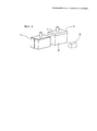
На фиг.1 схематично показано в аксонометрии оборудование для изготовления унитаза согласно изобретению,Figure 1 schematically shows in perspective the equipment for the manufacture of a toilet bowl according to the invention,
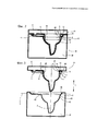
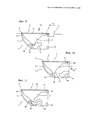
На фиг.2 показаны в разрезе сбоку выполненные в виде единого тела чаша и ободок, образующие часть унитаза, внутри закрытой литейной формы,Figure 2 shows a sectional side view made in the form of a single body bowl and rim, forming part of the toilet, inside a closed mold,
На фиг.3 показаны в разрезе сбоку выполненные в виде единого тела чаша и ободок, образующие часть унитаза, внутри открытой литейной формы,Figure 3 shows a sectional side view made in the form of a single body bowl and rim, forming part of the toilet, inside an open casting mold,
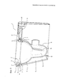
На фиг.4 показаны в аксонометрии, с частичным разрезом, выполненные в виде единого тела чаша и ободок, представленные на фиг.2 и 3,Figure 4 shows in a perspective view, in partial section, made in the form of a single body bowl and rim, presented in figure 2 and 3,
На фиг.5 показан в аксонометрии сбоку унитаз согласно изобретению, с частичным разрезом,Figure 5 shows a perspective view from the side of the toilet bowl according to the invention, with a partial section,
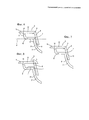
На фиг.6 показан спереди разрез трубчатой полости ободка, представленного на фиг.4,In Fig.6 shows a front section of a tubular cavity of the rim of Fig.4,
На фиг.7 показан вариант выполнения полости ободка, представленной на фиг.6,In Fig.7 shows an embodiment of the cavity of the rim presented in Fig.6,
На фиг.8 показан другой поперечный разрез полости ободка, отличный от фиг.6 и 7, на котором видны выступы внутри ободка.On Fig shows another cross section of the cavity of the rim, different from Fig.6 and 7, which shows the protrusions inside the rim.
На фиг.9-11 показаны схематично сбоку разные конструкции и соответствующие разные операции изготовления унитаза, при этом некоторые элементы убраны, чтобы были лучше видны другие.Figures 9-11 show schematically from the side different structures and the corresponding different operations for making the toilet, with some elements removed so that others are better visible.
ПОДРОБНОЕ ОПИСАНИЕ ПРЕДПОЧТИТЕЛЬНЫХ ВАРИАНТОВ ОСУЩЕСТВЛЕНИЯ ИЗОБРЕТЕНИЯDETAILED DESCRIPTION OF THE PREFERRED EMBODIMENTS
Согласно чертежам, в особенности фиг.1-5, способ изготовления керамического унитаза, обозначенного в целом цифровой позицией 1, осуществляется путем литья жидкости (известной как «шликер») в литейные формы из пористого полимера.According to the drawings, in particular FIGS. 1-5, a method for manufacturing a ceramic toilet bowl, indicated generally by
Изготавливаемый унитаз 1 содержит чашу 2 для сбора жидкостей, имеющую основную ось Z, проходящую по высоте, сифон 16 для слива жидкостей из чаши 2 и ободок 3 для распределения жидкости, имеющий часть, форма которой повторяет форму верхнего края 7 чаши 2, с которым она соединена по общей плоскости Р прилегания.The manufactured
«Основная ось, проходящая по высоте» - это продольная ось Z протяженности чаши 2, состоящей из верхней, широкой в поперечном сечении части, проходящей до дна или до нижней части чаши с более узким поперечным сечением по сравнению с верхней частью."The main axis passing through the height" is the longitudinal axis Z of the length of the
Ободок 3 содержит трубчатую полость 4 с тороидальным поперечным сечением для протекания жидкости, имеющую в качестве оси вращения, образующей тороид, указанную основную ось Z, проходящую по высоте чаши 2.The
Ободок 3 и чаша 2 сформированы как единое тело и представляют собой единый компонент.The
Унитаз 1 содержит наружный корпус 5 для размещения единого компонента, образованного чашей 2 и ободком 3.The
Корпус 5 предпочтительно вмещает и закрывает всю чашу 2, а часть ободка (по меньшей мере верхняя плоская поверхность) остается открытой и видна снаружи корпуса 5.The
Согласно изобретению способ изготовления унитаза 1 включает операцию обеспечения наличия первой литейной формы S1, состоящей из одной нижней охватывающей матрицы М, закрытой экстрактором E или верхней охватываемой частью, выполненной подвижной для открывания и закрывания по оси, перпендикулярной к общей плоскости P прилегания и параллельной основной оси Z, проходящей по высоте чаши 2 (см. фиг.1 и 2).According to the invention, the method of manufacturing the
Также согласно изобретению матрица M и экстрактор E выполнены так, что при использовании имеют первую группу периметрических поверхностей 40, 41, 42, формирующих трубчатую полость 4 и стенку 31, соединяющую между собой чашу 3 и ободок 4, и расположенных параллельно друг другу, и вторую группу формирующих поверхностей 43, 44 для соединения поверхностей первой группы 40, 41, 42 (см. фиг.1 и 2).Also according to the invention, the matrix M and the extractor E are made so that when used they have a first group of
Поверхности 43, 44 второй группы ориентированы поперек оси Z, проходящей по высоте, и расположены параллельно плоскости Р прилегания, для получения первой литейной формы S1 с непрерывными поверхностями, лишенными углублений или выступов, т.е. неровностей.The
Способ содержит также следующие операции:The method also contains the following operations:
- формирование чаши 2 и ободка 3 путем литья в первую литейную форму S1;- the formation of the
- обеспечение наличия второй литейной формы S2 для формирования корпуса 5;- providing a second mold S2 for forming the
- формирование корпуса 5 путем литья во вторую литейную форму S2;- the formation of the
- подъем экстрактора E с матрицы M (одним движением, см. фиг.3 и 4) для полного извлечения из литейной формы чаши 2 и ободка 3 как единого тела;- lifting the extractor E from the matrix M (in one motion, see FIGS. 3 and 4) to completely remove the
- открывание второй литейной формы S2 для подготовки верхней части корпуса 5 к размещению чаши 2 и ободка 3;- opening the second mold S2 to prepare the upper part of the
- вставку чаши 2 и ободка 3 в корпус 5 с опорой на него (см. фиг.9, стрелки F2 и F3).- insert the
Способ предпочтительно включает операцию присоединения сифона 16 к нижней части чаши 2, которую выполняют после вставки чаши 2 и ободка 3 в корпус 5.The method preferably includes the operation of attaching a siphon 16 to the bottom of the
Операция формирования корпуса 5 во второй литейной форме S2 предпочтительно включает одновременное формирование сифона 16 для слива жидкостей из чаши 2.The operation of forming the
Способ предпочтительно включает операцию нанесения связующего материала (например «шликера» с большим содержанием воды) на верхний край сифона 16.The method preferably includes the step of applying a binder material (for example, a "slip" with a high water content) on the upper edge of the siphon 16.
Альтернативно способ включает следующие дополнительные операции:Alternatively, the method includes the following additional steps:
- обеспечение наличия третьей литейной формы S3 для формирования сифона 16 для слива жидкостей со дна чаши 2;- providing a third mold S3 for forming a siphon 16 for draining liquids from the bottom of the
- формирование сифона 16 для слива жидкостей путем литья в третью литейную форму S3;- the formation of a siphon 16 for draining liquids by casting in a third mold S3;
- размещение сифона 16 для слива жидкостей в корпусе 5 после вставки чаши 2 и ободка 3 в корпус 5 (см. стрелку F4 на фиг.10);- placement of a siphon 16 for draining liquids in the
- присоединение сифона 16 к нижней части чаши 2.- the connection of the siphon 16 to the bottom of the
До операции размещения сифона 16 в корпусе 5 на верхнюю часть сифона 16 предпочтительно наносят связующий материал для присоединения к нижней части чаши 2.Prior to the operation of placing the siphon 16 in the
Чашу 2 предпочтительно подготавливают для присоединения сифона 16 путем удаления керамического материала с нижней зоны, которая включает в себя основание и часть задней боковой поверхности.The
Матрица M и экстрактор E предпочтительно выполнены так, что при использовании имеют две дополнительные формирующие поверхности 45 и 46, определяющие выступающий фланец 13 ободка 3.The matrix M and the extractor E are preferably made so that when used they have two additional forming
Как описано выше, керамический унитаз 1 согласно изобретению содержит чашу 2 с основной осью Z, проходящей по высоте, и ободок 3 для распределения жидкостей, имеющий часть, форма которой повторяет верхний край (7) чаши (2), с которым она соединена по общей плоскости (P) прилегания.As described above, the
Ободок 3 содержит трубчатую полость 4 для протекания жидкости, тороидальную в поперечном сечении, имеющую в качестве оси вращения, образующей тороид, указанную основную ось Z, проходящую по высоте чаши 2.The
Ободок 3 и чаша 2 сформированы как единое тело и образуют единый компонент.The
Унитаз 1 содержит наружный корпус 5 для размещения единого компонента, образованного чашей 2 и ободком 3.The
Корпус 5 предпочтительно вмещает и полностью закрывает всю чашу 2, а часть ободка 3 (по меньшей мере верхняя плоская поверхность) остается видна на наружной стороне корпуса 5.The
Унитаз 1 согласно изобретению содержит:The
первую группу периметрических поверхностей 8, 14, 31, которые определяют одну часть трубчатой полости 4 ободка 3 и поверхность, соединяющую друг с другом чашу 2 и ободок 3, и которые параллельны друг другу и проходят в направлении, поперечном к общей плоскости Р прилегания.the first group of
Кроме того, согласно изобретению унитаз 1 содержит вторую группу периметрических поверхностей 6, 12, которые определяют другую часть трубчатой полости 4, проходят параллельно плоскости P прилегания и соединены с поверхностями 8, 14, 31 первой группы, так что образуются непрерывные наружные поверхности, которые не имеют углублений или выступов на чаше/ободке.In addition, according to the invention, the
Одна из поверхностей второй группы, а именно поверхность 12, определяющая верхнюю стенку трубчатой полости 4, снабжена выступающим фланцем 13, образующим поверхность для опоры ободка 3 на верхнюю поверхность корпуса 5.One of the surfaces of the second group, namely the
В первой группе поверхностей предпочтительно имеются две поверхности ободка 3, определяющие наружную боковую сторону 14 и внутреннюю боковую сторону 8 трубчатой полости 4, и поверхность 31, соединяющую чашу 2 и ободок 3, которые проходят линейно с наклоном к центру чаши 2.In the first group of surfaces, there are preferably two surfaces of the
Предпочтительно, чтобы эти три поверхности 8, 14, 31 были по существу параллельны между собой.Preferably, these three
Периметрические поверхности каждой из двух групп параллельны друг другу и определяют форму верхней части унитаза 1 с линейными соединительными поверхностями, расположенными параллельно или поперек оси Z или общей плоскости Р прилегания, так что геометрия указанных поверхностей не имеет нерегулярностей.The perimetric surfaces of each of the two groups are parallel to each other and determine the shape of the upper part of the
Объем трубчатой полости 4 частично ограничен также соединительной поверхностью 31, определяющей верхний край 7 чаши 2 и ободка 3.The volume of the
Соединительная поверхность 31 фактически соединена, без прерывания, с нижней поверхностью 6 ободка 3 так, что край ободка 3 выступает наружу от чаши 2.The connecting
Благодаря такой геометрии получается по существу четырехугольная в поперечном сечении трубчатая полость 4 без углублений или выступов, направленных горизонтально как внутрь, так и наружу чаши 2.Due to this geometry, a
Такая геометрия позволяет изготовить чашу 2 и ободок 3 по существу в одной литейной форме, которая открывается путем перемещения ее двух частей только в одном направлении, а именно перпендикулярном к общей плоскости P прилегания чаши и ободка 3 и параллельном основной оси Z, проходящей по высоте чаши 2 (как указано выше).Such a geometry makes it possible to make the
Ободок 3 предпочтительно содержит трубчатую полость 4, нижняя поверхность 6 которой присоединена своим концом к соединительной поверхности 31 (в частности, к ее верхнему краю 7) чаши 2 так, что образуется по существу прямой угол α, определяющий выступающую наружу расширенную часть чаши 2 (см. фиг.6).The
Ободок 3 предпочтительно содержит фланец 8, проходящий внутрь чаши 2 (определяющий одну из поверхностей, поперечных к общей плоскости P прилегания), расположенный по существу вертикально и определяющий внутреннюю боковую поверхность трубчатой полости 4.The
Фланец 8 имеет нижнюю свободную часть, частично обращенную к верхнему краю 7 и к соединительной поверхности 31 чаши 2 и определяющую канал 9 для слива жидкости, протекающей по трубчатой полости 4.The
Более конкретно, фланец 8 проходит за верхний край 7 чаши 2, так что он обращен также к нижней части соединительной поверхности 31 чаши 2 и находится на постоянном расстоянии от нее, образуя более длинный канал 9 для слива жидкости, что позволяет лучше направлять выходящую жидкость.More specifically, the
В альтернативном варианте расстояние между фланцем 8 и соединительной поверхностью 31 чаши 2 может изменяться, чтобы в канале 9 для слива жидкостей были более узкие или более широкие зоны.Alternatively, the distance between the
Это предпочтительно достигается благодаря волнистой форме соединительной поверхности 31 чаши 2.This is preferably achieved due to the wavy shape of the connecting
Как альтернатива, не ограничивающая изобретения, это достигается путем изменения угла B наклона фланца 8 относительно верхней стенки 12 трубчатой полости 4.As an alternative, not limiting the invention, this is achieved by changing the angle B of the inclination of the
В обоих возможных описанных вариантах внутренний фланец 8 трубчатой полости 4 имеет промежуточный участок 10, который соединен с участком, соединяющим друг с другом нижнюю поверхность 6 и верхний край 7 чаши 2, для образования закрытой зоны по длине трубчатой полости 4. Эта зона, чередующаяся с открытыми зонами трубчатой полости 4, определяет закрытый ободок (см. фиг.7).In both possible described embodiments, the
Нижняя поверхность 6 трубчатой полости 4 предпочтительно содержит выступы 11, отходящие внутрь трубчатой полости 4, для распределения проходящей жидкости (см. фиг.8).The
Выступы 11 распределены по всей трубчатой полости 4, чередуясь с линейными участками нижней поверхности 6.The
Благодаря такой форме нижней части трубчатой полости 4 можно регулировать сужение потока жидкости и ее распределение, чтобы оптимизировать ее распределение по всей полости 4 и, следовательно, по внутренней стенке чаши 2.Due to this shape of the lower part of the
Как указано выше, ободок 3 имеет поверхность 12, определяющую верхнюю стенку трубчатой полости 4, снабженную фланцем 13, отходящим от наружной боковой поверхности 14 трубчатой полости 4.As indicated above, the
Выступающий фланец 13 определяет поверхность, которой ободок 3 опирается на верхнюю поверхность 15 корпуса 5.The protruding
Фланец 13 образует угол δ с наружной боковой стенкой 14 и расположен по существу параллельно нижней поверхности 6 трубчатой полости 4.The
Согласно изобретению, унитаз 1 содержит сифон 16 для слива жидкостей из чаши 2, который выполнен с возможностью соединения с нижней частью чаши 2, находящейся внутри корпуса 5.According to the invention, the
Сифон 16 выполнен как единое тело с корпусом 5 (см. фиг.9).The siphon 16 is made as a single body with a housing 5 (see Fig.9).
Сифон 16 предпочтительно сформирован на нижней части корпуса 5.The siphon 16 is preferably formed on the lower part of the
Благодаря этому дополнительно упрощается исходная форма компонентов унитаза и, следовательно, оборудование для его изготовления.Thanks to this, the initial shape of the toilet bowl components and, consequently, the equipment for its manufacture are further simplified.
Кроме того, ускоряется сборка компонентов унитаза 1 благодаря использованию операции вставки чаши 2 с ободком в корпус 5 с целью соединения нижней части чаши 2 с сифоном 16.In addition, the assembly of toilet bowl components is accelerated by using the operation of inserting the
Сифон 16 предпочтительно сформирован вместе с ребром 19 жесткости внутри корпуса 5.The siphon 16 is preferably formed with a stiffening
Это ребро 19, вместе с задним кронштейном 20 и ребром 21, также обеспечивает частичную опору чаши 2 и части ободка 3 в корпусе 5.This
В альтернативном варианте (см. фиг.10 и 11, на которых показаны два сифона другой формы) сифон 16 является отдельным от чаши 2 компонентом и соединяется с нижней частью чаши 2, размещенной внутри корпуса 5.Alternatively (see FIGS. 10 and 11, which show two siphons of a different shape), the siphon 16 is a component separate from the
В этом случае сифон 16 формируют отдельно от компонентов унитаза 1 и затем приставляют к нижней части чаши, уже находящейся в корпусе 5.In this case, the siphon 16 is formed separately from the components of the
Это позволяет выбирать тип сифона 16, устанавливаемого в унитаз 1, позднее.This allows you to choose the type of siphon 16, installed in the
Зоны контакта между сифоном 16 и дном чаши 2 выполнены с возможностью их плотного прилеганием друг к другу на операции окончательного соединения.The contact zones between the siphon 16 and the bottom of the
В связи с этим чаша 2 открыта на дне 2a и/или на боковой поверхности 2b, в зависимости от типа присоединяемого сифона 16, т.е. от типа отверстия на сифоне 16.In this regard, the
Ободок 3 предпочтительно содержит вторую заднюю часть 17, которая определяется удлиненным участком части, образующей трубчатую полость 4, и внутри которой находится канал 18 для подачи жидкости в трубчатую полость 4.The
Предлагаемые способ и унитаз позволяют достичь указанных целей благодаря особой конструктивной форме чаши и ободка.The proposed method and the toilet can achieve these goals due to the special structural shape of the bowl and rim.
В частности, благодаря геометрической непрерывности верхнего края чаши и нижней части ободка, в сочетании с линейностью поверхностей, определяющих трубчатую полость, можно получить форму без расположенных горизонтально углублений или выступов, так что два объединенных компонента могут быть изготовлены в одной литейной форме, состоящей только из двух частей и имеющей очень простую конструкцию.In particular, due to the geometric continuity of the upper edge of the bowl and the lower part of the rim, in combination with the linearity of the surfaces defining the tubular cavity, it is possible to obtain a mold without horizontally located recesses or protrusions, so that the two combined components can be made in one mold, consisting only of two parts and having a very simple design.
Все это достигается при соблюдении высоких стандартов качества и внешнего вида унитаза и гарантии его надежной работы.All this is achieved while observing high standards of quality and appearance of the toilet and guaranteeing its reliable operation.
Выполнение сифона отдельно от чаши позволяет еще больше упростить литейную форму для изготовления чаши с ободком и в то же время выбрать наиболее подходящий тип сифона.The implementation of the siphon separately from the bowl allows you to further simplify the mold for making a bowl with a rim and at the same time choose the most suitable type of siphon.
Это повышает возможность приспособить унитаз к окружающей обстановке, в которой он будет установлен, в отношении не только его внешнего вида, но и функциональных требований.This increases the ability to adapt the toilet to the environment in which it will be installed, regarding not only its appearance, but also its functional requirements.
Claims (16)
- чашу (2) для сбора жидкостей, имеющую основную ось Z, проходящую по высоте;
- ободок (3) для распределения жидкости, имеющий по меньшей мере одну часть, форма которой повторяет верхний край (7) чаши (2) по общей плоскости (P) прилегания и которая имеет тороидальную в поперечном сечении трубчатую полость (4) для протекания жидкости, имеющую в качестве образующей оси указанную ось (Z) чаши (2); и
- отдельный наружный корпус (5) для размещения чаши (2) и ободка (3),
отличающийся тем, что он включает следующие операции:
- обеспечение наличия первой литейной формы (S1), состоящей из одной нижней охватывающей матрицы (M), закрытой экстрактором (E) или верхней охватываемой частью, которая выполнена подвижной для открывания и закрывания по оси, перпендикулярной к общей плоскости (P) прилегания и параллельной основной оси (Z), проходящей по высоте, причем матрица (M) и экстрактор (E) выполнены так, что при использовании имеют
- первую группу периметрических поверхностей (40, 41, 42), формирующих одну часть трубчатой полости (4) и стенку (31), соединяющую друг с другом ободок (3) и чашу (4), и ориентированных параллельно друг другу, и
- вторую группу формирующих поверхностей (43, 44) для соединения между собой указанных поверхностей (40, 41, 42) первой группы, причем поверхности (43, 44) второй группы ориентированы поперек основной оси (Z), проходящей по высоте, и параллельно плоскости (P) прилегания, для получения первой литейной формы (S1) с непрерывными поверхностями, не имеющими углублений или выступов, т.е. неровностей;
- формирование чаши (2) и ободка (3) путем литья в первую литейную форму (S1);
- обеспечение наличия второй литейной формы (S2) для формирования корпуса (5);
- формирование корпуса (5) путем литья во вторую литейную форму (S2);
- подъем экстрактора (Е) с матрицы первой литейной формы (S1) с целью полного извлечения из формы чаши (2) и ободка (3) как единого тела;
- открывание второй литейной формы (S2) для подготовки верхней части корпуса (5) к размещению чаши (2) и ободка (3); и
- вставку чаши (2) и ободка (3) в корпус (5) с опорой на корпус.1. A method of manufacturing a toilet containing:
- a liquid collecting cup (2) having a main Z axis extending in height;
- a rim (3) for distributing the liquid, having at least one part, the shape of which repeats the upper edge (7) of the bowl (2) along the common contact plane (P) and which has a tubular cavity (4) toroidal in cross section for the liquid to flow having the axis of the specified axis (Z) of the bowl (2); and
- a separate outer casing (5) to accommodate the bowl (2) and the rim (3),
characterized in that it includes the following operations:
- providing a first mold (S1) consisting of one lower female die (M) closed by an extractor (E) or upper male part that is movable to open and close along an axis perpendicular to the common contact plane (P) and parallel the main axis (Z), passing along the height, and the matrix (M) and the extractor (E) are made so that when used have
- the first group of perimeter surfaces (40, 41, 42) forming one part of the tubular cavity (4) and the wall (31) connecting the rim (3) and the bowl (4) with each other, and oriented parallel to each other, and
- a second group of forming surfaces (43, 44) for connecting together the indicated surfaces (40, 41, 42) of the first group, and the surfaces (43, 44) of the second group are oriented transverse to the main axis (Z), passing along the height, and parallel to the plane (P) fit, to obtain the first mold (S1) with continuous surfaces without recesses or protrusions, i.e. irregularities;
- the formation of the bowl (2) and the rim (3) by casting in the first mold (S1);
- ensuring the presence of a second mold (S2) for forming the body (5);
- the formation of the body (5) by casting in a second mold (S2);
- lifting the extractor (E) from the matrix of the first casting mold (S1) in order to completely remove the cup (2) and rim (3) from the mold as a single body;
- opening the second mold (S2) to prepare the upper part of the body (5) to place the bowl (2) and the rim (3); and
- insertion of the bowl (2) and the rim (3) into the housing (5) with support on the housing.
- обеспечение наличия третьей литейной формы (S3) для формирования сифона (16) для слива жидкостей из нижней части чаши (2);
- формирование сифона (16) для слива жидкостей путем литья в третью литейную форму (S3);
- размещение указанного сифона (16) в корпусе после вставки чаши (2) и ободка (3) в корпус (5); и
- присоединение сифона (16) к нижней части чаши (2).4. The method according to claim 1 or 3, including the following additional operations:
- providing a third mold (S3) for forming a siphon (16) for draining liquids from the bottom of the bowl (2);
- the formation of a siphon (16) for draining liquids by casting in a third mold (S3);
- placement of the specified siphon (16) in the housing after inserting the bowl (2) and the rim (3) into the housing (5); and
- attaching a siphon (16) to the bottom of the bowl (2).
- чашу (2) для сбора жидкостей, имеющую основную ось (Z), проходящую по высоте;
- ободок (3) для распределения жидкости, имеющий по меньшей мере одну часть, форма которой повторяет верхний край (7) чаши (2) по общей плоскости (P) прилегания и которая имеет тороидальную в поперечном сечении трубчатую полость (4) для протекания жидкостей, имеющую в качестве оси вращения указанную ось (Z) чаши (2), причем ободок (3) и чаша (2) изготовлены в литейной форме (S1) как единое тело; и
- отдельный наружный корпус (5) для размещения единого компонента, образованного чашей (2) и ободком (3),
отличающийся тем, что
- первая группа периметрических поверхностей (8, 14, 31), которые определяют одну часть трубчатой полости (4) ободка (3), и поверхность, соединяющая часть (3) ободка с чашей (2), параллельны друг другу и проходят в направлении, поперечном к общей плоскости (P) прилегания,
- а вторая группа периметрических поверхностей (6, 12), которые определяют другую часть трубчатой полости (4), проходят параллельно плоскости (Р) прилегания и соединены с первой группой поверхностей (8, 14, 31) с образованием непрерывных наружных поверхностей без углублений или выступов; причем одна поверхность (12) второй группы, определяющая верхнюю стенку трубчатой полости (4), снабжена выступающим фланцем (13), образующим поверхность (3) для опоры ободка (3) на верхнюю поверхность (15) корпуса (5).6. Ceramic toilet bowl made by molding in a mold using the method according to claims 1-5, containing:
- a liquid collecting cup (2) having a main axis (Z) extending in height;
- a rim (3) for distributing liquid, having at least one part, the shape of which repeats the upper edge (7) of the bowl (2) along the common contact plane (P) and which has a tubular cavity (4) toroidal in cross section for the flow of liquids having the specified axis (Z) of the bowl (2) as the axis of rotation, the rim (3) and the bowl (2) being made in the mold (S1) as a single body; and
- a separate outer casing (5) for accommodating a single component formed by a bowl (2) and a rim (3),
characterized in that
- the first group of perimeter surfaces (8, 14, 31) that define one part of the tubular cavity (4) of the rim (3), and the surface connecting the part (3) of the rim with the cup (2) are parallel to each other and extend in the direction transverse to the common plane (P) of the fit,
- and the second group of perimeter surfaces (6, 12), which define another part of the tubular cavity (4), run parallel to the contact plane (P) and are connected to the first group of surfaces (8, 14, 31) with the formation of continuous external surfaces without recesses or protrusions; moreover, one surface (12) of the second group defining the upper wall of the tubular cavity (4) is provided with a protruding flange (13) forming a surface (3) for supporting the rim (3) on the upper surface (15) of the housing (5).
Applications Claiming Priority (3)
| Application Number | Priority Date | Filing Date | Title |
|---|---|---|---|
| ITBO2011A000201 | 2011-04-15 | ||
| IT000201A ITBO20110201A1 (en) | 2011-04-15 | 2011-04-15 | SANITARY VASE IN CERAMIC MATERIAL. |
| PCT/IB2012/051824 WO2012140607A2 (en) | 2011-04-15 | 2012-04-13 | Ceramic toilet bowl and method for manufacturing the bowl |
Publications (2)
| Publication Number | Publication Date |
|---|---|
| RU2013145147A RU2013145147A (en) | 2015-05-20 |
| RU2584017C2 true RU2584017C2 (en) | 2016-05-20 |
Family
ID=44554130
Family Applications (1)
| Application Number | Title | Priority Date | Filing Date |
|---|---|---|---|
| RU2013145147/13A RU2584017C2 (en) | 2011-04-15 | 2012-04-13 | Ceramic toilet bowl and manufacturing method thereof |
Country Status (10)
| Country | Link |
|---|---|
| US (1) | US9290922B2 (en) |
| EP (1) | EP2697442B1 (en) |
| CN (1) | CN103502544B (en) |
| BR (1) | BR112013026439B1 (en) |
| ES (1) | ES2663401T3 (en) |
| IT (1) | ITBO20110201A1 (en) |
| MX (1) | MX339906B (en) |
| PL (1) | PL2697442T3 (en) |
| RU (1) | RU2584017C2 (en) |
| WO (1) | WO2012140607A2 (en) |
Cited By (1)
| Publication number | Priority date | Publication date | Assignee | Title |
|---|---|---|---|---|
| RU186660U1 (en) * | 2018-09-04 | 2019-01-28 | Алексей Вячеславович Бузунов | TOILET BOWL |
Families Citing this family (15)
| Publication number | Priority date | Publication date | Assignee | Title |
|---|---|---|---|---|
| CN103831887A (en) * | 2014-03-17 | 2014-06-04 | 唐山森兰瓷科技有限公司 | Individual type high-pressure grouting forming machine |
| US9719239B2 (en) | 2014-03-18 | 2017-08-01 | Kohler India Corporation Private Limited | Dual-jet toilet |
| US10060113B2 (en) | 2014-03-21 | 2018-08-28 | Kohler Co. | Rimless toilet |
| US10631711B2 (en) * | 2016-02-25 | 2020-04-28 | Munchkin, Inc. | Modular bottle rack |
| US10711442B2 (en) | 2016-04-26 | 2020-07-14 | Kohler Co. | Composite faucet body and internal waterway |
| BR102018010327B1 (en) | 2017-05-22 | 2023-12-12 | Kohler Co | TOILET ASSEMBLY AND PLUMBING ACCESSORIES |
| US11118338B2 (en) | 2017-05-22 | 2021-09-14 | Kohler Co. | Plumbing fixtures with insert-molded components |
| TWI633990B (en) * | 2017-09-01 | 2018-09-01 | 和成欣業股份有限公司 | High pressure molding method and toilet body formed by using the same |
| CN108407048A (en) * | 2018-03-14 | 2018-08-17 | 唐山奇隆洁具有限公司 | Automatic closestool at blank technology |
| CA3110062A1 (en) * | 2018-08-31 | 2020-03-05 | As America, Inc. | Toilet assembly |
| CN110000894B (en) * | 2019-03-26 | 2024-01-30 | 佛山市顺德区乐华陶瓷洁具有限公司 | High-strength closestool and preparation method thereof |
| CN110053132B (en) * | 2019-03-26 | 2024-01-30 | 佛山市顺德区乐华陶瓷洁具有限公司 | Toilet bowl and preparation method thereof |
| CN110195461B (en) * | 2019-07-04 | 2023-11-07 | 九牧厨卫股份有限公司 | Blank component of squatting pan, manufacturing method of squatting pan and squatting pan |
| CN111531677B (en) * | 2020-05-09 | 2021-06-25 | 广东世冠威卫浴有限公司 | Blank forming method of sinking type water tank closestool and sinking type water tank closestool |
| US20230036047A1 (en) * | 2021-07-29 | 2023-02-02 | Kohler Co. | Toilet with canned sump |
Citations (3)
| Publication number | Priority date | Publication date | Assignee | Title |
|---|---|---|---|---|
| GB2161104A (en) * | 1984-07-02 | 1986-01-08 | Armitage Shanks Ltd | Moulding sanitary appliances |
| RU2302494C1 (en) * | 2005-12-02 | 2007-07-10 | Игорь Сергеевич Соловьев | Peaked toilet bowl, molded housing thereof and toilet bowl venting device (variants) |
| EP2017391A2 (en) * | 2007-07-20 | 2009-01-21 | Sacmi Cooperativa Meccanici Imola Societa' Cooperativa | A ceramic sanitary fixture |
Family Cites Families (7)
| Publication number | Priority date | Publication date | Assignee | Title |
|---|---|---|---|---|
| DE60134843D1 (en) | 2000-04-10 | 2008-08-28 | Inax Corp | WC ACCORDING TO WESTERN STANDARD |
| US20030115664A1 (en) | 2001-08-13 | 2003-06-26 | Tatsuhiro Kosugi | Toilet and method for manufacture of the same |
| JP3817734B2 (en) | 2002-09-03 | 2006-09-06 | 東陶機器株式会社 | Flush toilet |
| JP2005113519A (en) | 2003-10-08 | 2005-04-28 | Toto Ltd | Manufacturing method of water closet and water closet |
| US7263758B2 (en) * | 2003-12-02 | 2007-09-04 | American Standard Intl. Inc. | System and method for casting toilet bowls |
| CN1769605A (en) | 2004-11-03 | 2006-05-10 | 和成欣业股份有限公司 | Toilet upper water outlet forming method and its structure |
| CN102230321B (en) * | 2011-04-12 | 2013-06-05 | 上海琥达投资发展有限公司 | Water-saving thermoplastic-resin-base novel composite material closestool and preparation method thereof |
-
2011
- 2011-04-15 IT IT000201A patent/ITBO20110201A1/en unknown
-
2012
- 2012-04-13 PL PL12718400T patent/PL2697442T3/en unknown
- 2012-04-13 US US14/111,241 patent/US9290922B2/en not_active Expired - Fee Related
- 2012-04-13 RU RU2013145147/13A patent/RU2584017C2/en active
- 2012-04-13 CN CN201280018605.2A patent/CN103502544B/en not_active Expired - Fee Related
- 2012-04-13 EP EP12718400.0A patent/EP2697442B1/en active Active
- 2012-04-13 ES ES12718400.0T patent/ES2663401T3/en active Active
- 2012-04-13 WO PCT/IB2012/051824 patent/WO2012140607A2/en active Application Filing
- 2012-04-13 BR BR112013026439-0A patent/BR112013026439B1/en not_active IP Right Cessation
- 2012-04-13 MX MX2013011986A patent/MX339906B/en active IP Right Grant
Patent Citations (3)
| Publication number | Priority date | Publication date | Assignee | Title |
|---|---|---|---|---|
| GB2161104A (en) * | 1984-07-02 | 1986-01-08 | Armitage Shanks Ltd | Moulding sanitary appliances |
| RU2302494C1 (en) * | 2005-12-02 | 2007-07-10 | Игорь Сергеевич Соловьев | Peaked toilet bowl, molded housing thereof and toilet bowl venting device (variants) |
| EP2017391A2 (en) * | 2007-07-20 | 2009-01-21 | Sacmi Cooperativa Meccanici Imola Societa' Cooperativa | A ceramic sanitary fixture |
Cited By (1)
| Publication number | Priority date | Publication date | Assignee | Title |
|---|---|---|---|---|
| RU186660U1 (en) * | 2018-09-04 | 2019-01-28 | Алексей Вячеславович Бузунов | TOILET BOWL |
Also Published As
| Publication number | Publication date |
|---|---|
| US20140026311A1 (en) | 2014-01-30 |
| BR112013026439A2 (en) | 2016-12-20 |
| ES2663401T3 (en) | 2018-04-12 |
| CN103502544B (en) | 2015-11-25 |
| EP2697442B1 (en) | 2018-01-31 |
| WO2012140607A2 (en) | 2012-10-18 |
| WO2012140607A3 (en) | 2012-12-27 |
| BR112013026439B1 (en) | 2020-11-10 |
| ITBO20110201A1 (en) | 2012-10-16 |
| MX2013011986A (en) | 2013-11-04 |
| MX339906B (en) | 2016-06-15 |
| EP2697442A2 (en) | 2014-02-19 |
| RU2013145147A (en) | 2015-05-20 |
| CN103502544A (en) | 2014-01-08 |
| PL2697442T3 (en) | 2018-06-29 |
| US9290922B2 (en) | 2016-03-22 |
Similar Documents
| Publication | Publication Date | Title |
|---|---|---|
| RU2584017C2 (en) | Ceramic toilet bowl and manufacturing method thereof | |
| RU2457297C2 (en) | Ceramic plumbing fixture | |
| US8528123B2 (en) | Exterior rim wash bowl | |
| RU2592614C2 (en) | Ceramic toilet bowl | |
| US7353577B2 (en) | System and method for casting toilet bowls | |
| KR101962616B1 (en) | water tank type toilet stool of one piece and its manufacturing method | |
| KR101204787B1 (en) | Toilet stool of one piece type and its manufacturing method | |
| JP2018096177A (en) | Toilet bowl manufacturing method | |
| JP2005113519A (en) | Manufacturing method of water closet and water closet | |
| RU219193U1 (en) | SPLIT FORM FOR PRESSING CHEESE | |
| KR100586404B1 (en) | Molding apparatus for watertight board of bathroom | |
| CN219992633U (en) | Squatting pan | |
| CN211816728U (en) | Closestool and forming die thereof | |
| JPH0579090A (en) | Flush toilet stool and manufacture thereof | |
| JPH08270050A (en) | Toilet closet | |
| CN116641459A (en) | Squatting pan and preparation method thereof | |
| JPH0594378U (en) | Stall Urinal Mold Mold Sludge Passage | |
| JPH05285922A (en) | Casting mold of sanitation fixture | |
| KR20050082608A (en) | Closet with drain pipe in a body and method thereof | |
| PL116838B1 (en) | Water-closet bowl and a mould for casting such bowls |