RU2582710C2 - Device for processing polymer material - Google Patents
Device for processing polymer material Download PDFInfo
- Publication number
- RU2582710C2 RU2582710C2 RU2014119374/05A RU2014119374A RU2582710C2 RU 2582710 C2 RU2582710 C2 RU 2582710C2 RU 2014119374/05 A RU2014119374/05 A RU 2014119374/05A RU 2014119374 A RU2014119374 A RU 2014119374A RU 2582710 C2 RU2582710 C2 RU 2582710C2
- Authority
- RU
- Russia
- Prior art keywords
- hopper
- mixing
- conveyor
- rotation
- screw
- Prior art date
Links
- 239000002861 polymer material Substances 0.000 title claims abstract description 21
- 238000012545 processing Methods 0.000 title abstract description 8
- 239000000463 material Substances 0.000 claims abstract description 66
- 238000002156 mixing Methods 0.000 claims abstract description 63
- 238000000227 grinding Methods 0.000 claims abstract description 57
- 230000000694 effects Effects 0.000 claims abstract description 14
- 229920000642 polymer Polymers 0.000 claims abstract description 7
- 239000013598 vector Substances 0.000 claims description 33
- 230000006835 compression Effects 0.000 claims description 8
- 238000007906 compression Methods 0.000 claims description 8
- 238000011144 upstream manufacturing Methods 0.000 claims description 8
- 238000010438 heat treatment Methods 0.000 claims description 4
- 238000004064 recycling Methods 0.000 claims description 2
- 238000005054 agglomeration Methods 0.000 claims 1
- 230000002776 aggregation Effects 0.000 claims 1
- 238000007781 pre-processing Methods 0.000 claims 1
- 229920001169 thermoplastic Polymers 0.000 claims 1
- 239000002699 waste material Substances 0.000 claims 1
- 239000000126 substance Substances 0.000 abstract 1
- 239000000047 product Substances 0.000 description 11
- 238000009434 installation Methods 0.000 description 10
- 238000002844 melting Methods 0.000 description 9
- 230000008018 melting Effects 0.000 description 9
- 238000012856 packing Methods 0.000 description 9
- 239000000155 melt Substances 0.000 description 7
- 239000002245 particle Substances 0.000 description 7
- 230000032258 transport Effects 0.000 description 7
- 238000011068 loading method Methods 0.000 description 6
- 239000000565 sealant Substances 0.000 description 6
- 208000007536 Thrombosis Diseases 0.000 description 5
- 230000009471 action Effects 0.000 description 5
- 230000007423 decrease Effects 0.000 description 4
- 238000011049 filling Methods 0.000 description 4
- 230000002441 reversible effect Effects 0.000 description 4
- 230000008901 benefit Effects 0.000 description 3
- 238000013461 design Methods 0.000 description 3
- 235000011837 pasties Nutrition 0.000 description 3
- 230000015572 biosynthetic process Effects 0.000 description 2
- 238000004140 cleaning Methods 0.000 description 2
- 238000006073 displacement reaction Methods 0.000 description 2
- 239000002657 fibrous material Substances 0.000 description 2
- 238000012423 maintenance Methods 0.000 description 2
- 238000000034 method Methods 0.000 description 2
- 239000000203 mixture Substances 0.000 description 2
- 239000012768 molten material Substances 0.000 description 2
- -1 polyethylene Polymers 0.000 description 2
- 229920006254 polymer film Polymers 0.000 description 2
- 230000008569 process Effects 0.000 description 2
- 230000008439 repair process Effects 0.000 description 2
- 238000012360 testing method Methods 0.000 description 2
- 238000012546 transfer Methods 0.000 description 2
- 230000007704 transition Effects 0.000 description 2
- 241000273930 Brevoortia tyrannus Species 0.000 description 1
- 239000004698 Polyethylene Substances 0.000 description 1
- 239000004743 Polypropylene Substances 0.000 description 1
- 238000009825 accumulation Methods 0.000 description 1
- 230000001154 acute effect Effects 0.000 description 1
- 230000005540 biological transmission Effects 0.000 description 1
- 238000005056 compaction Methods 0.000 description 1
- 230000000052 comparative effect Effects 0.000 description 1
- 230000006837 decompression Effects 0.000 description 1
- 230000002542 deteriorative effect Effects 0.000 description 1
- 238000011161 development Methods 0.000 description 1
- 230000018109 developmental process Effects 0.000 description 1
- 238000005265 energy consumption Methods 0.000 description 1
- 238000001125 extrusion Methods 0.000 description 1
- 239000000835 fiber Substances 0.000 description 1
- 239000012467 final product Substances 0.000 description 1
- 239000008187 granular material Substances 0.000 description 1
- 230000005484 gravity Effects 0.000 description 1
- 230000035764 nutrition Effects 0.000 description 1
- 235000016709 nutrition Nutrition 0.000 description 1
- 230000000737 periodic effect Effects 0.000 description 1
- 239000004014 plasticizer Substances 0.000 description 1
- 229920000747 poly(lactic acid) Polymers 0.000 description 1
- 229920000573 polyethylene Polymers 0.000 description 1
- 239000004626 polylactic acid Substances 0.000 description 1
- 229920001155 polypropylene Polymers 0.000 description 1
- 230000002028 premature Effects 0.000 description 1
- 238000002203 pretreatment Methods 0.000 description 1
- 230000005855 radiation Effects 0.000 description 1
- 238000011160 research Methods 0.000 description 1
- 238000007789 sealing Methods 0.000 description 1
- 239000007787 solid Substances 0.000 description 1
Images
Classifications
-
- B—PERFORMING OPERATIONS; TRANSPORTING
- B29—WORKING OF PLASTICS; WORKING OF SUBSTANCES IN A PLASTIC STATE IN GENERAL
- B29C—SHAPING OR JOINING OF PLASTICS; SHAPING OF MATERIAL IN A PLASTIC STATE, NOT OTHERWISE PROVIDED FOR; AFTER-TREATMENT OF THE SHAPED PRODUCTS, e.g. REPAIRING
- B29C48/00—Extrusion moulding, i.e. expressing the moulding material through a die or nozzle which imparts the desired form; Apparatus therefor
- B29C48/25—Component parts, details or accessories; Auxiliary operations
- B29C48/36—Means for plasticising or homogenising the moulding material or forcing it through the nozzle or die
- B29C48/395—Means for plasticising or homogenising the moulding material or forcing it through the nozzle or die using screws surrounded by a cooperating barrel, e.g. single screw extruders
- B29C48/40—Means for plasticising or homogenising the moulding material or forcing it through the nozzle or die using screws surrounded by a cooperating barrel, e.g. single screw extruders using two or more parallel screws or at least two parallel non-intermeshing screws, e.g. twin screw extruders
-
- B—PERFORMING OPERATIONS; TRANSPORTING
- B01—PHYSICAL OR CHEMICAL PROCESSES OR APPARATUS IN GENERAL
- B01F—MIXING, e.g. DISSOLVING, EMULSIFYING OR DISPERSING
- B01F35/00—Accessories for mixers; Auxiliary operations or auxiliary devices; Parts or details of general application
- B01F35/71—Feed mechanisms
-
- B—PERFORMING OPERATIONS; TRANSPORTING
- B01—PHYSICAL OR CHEMICAL PROCESSES OR APPARATUS IN GENERAL
- B01F—MIXING, e.g. DISSOLVING, EMULSIFYING OR DISPERSING
- B01F35/00—Accessories for mixers; Auxiliary operations or auxiliary devices; Parts or details of general application
- B01F35/75—Discharge mechanisms
- B01F35/754—Discharge mechanisms characterised by the means for discharging the components from the mixer
- B01F35/75455—Discharge mechanisms characterised by the means for discharging the components from the mixer using a rotary discharge means, e.g. a screw beneath the receptacle
- B01F35/754551—Discharge mechanisms characterised by the means for discharging the components from the mixer using a rotary discharge means, e.g. a screw beneath the receptacle using helical screws
-
- B—PERFORMING OPERATIONS; TRANSPORTING
- B02—CRUSHING, PULVERISING, OR DISINTEGRATING; PREPARATORY TREATMENT OF GRAIN FOR MILLING
- B02C—CRUSHING, PULVERISING, OR DISINTEGRATING IN GENERAL; MILLING GRAIN
- B02C18/00—Disintegrating by knives or other cutting or tearing members which chop material into fragments
- B02C18/06—Disintegrating by knives or other cutting or tearing members which chop material into fragments with rotating knives
- B02C18/08—Disintegrating by knives or other cutting or tearing members which chop material into fragments with rotating knives within vertical containers
- B02C18/086—Disintegrating by knives or other cutting or tearing members which chop material into fragments with rotating knives within vertical containers specially adapted for disintegrating plastics, e.g. cinematographic films
-
- B—PERFORMING OPERATIONS; TRANSPORTING
- B02—CRUSHING, PULVERISING, OR DISINTEGRATING; PREPARATORY TREATMENT OF GRAIN FOR MILLING
- B02C—CRUSHING, PULVERISING, OR DISINTEGRATING IN GENERAL; MILLING GRAIN
- B02C18/00—Disintegrating by knives or other cutting or tearing members which chop material into fragments
- B02C18/06—Disintegrating by knives or other cutting or tearing members which chop material into fragments with rotating knives
- B02C18/08—Disintegrating by knives or other cutting or tearing members which chop material into fragments with rotating knives within vertical containers
- B02C18/12—Disintegrating by knives or other cutting or tearing members which chop material into fragments with rotating knives within vertical containers with drive arranged below container
-
- B—PERFORMING OPERATIONS; TRANSPORTING
- B02—CRUSHING, PULVERISING, OR DISINTEGRATING; PREPARATORY TREATMENT OF GRAIN FOR MILLING
- B02C—CRUSHING, PULVERISING, OR DISINTEGRATING IN GENERAL; MILLING GRAIN
- B02C18/00—Disintegrating by knives or other cutting or tearing members which chop material into fragments
- B02C18/06—Disintegrating by knives or other cutting or tearing members which chop material into fragments with rotating knives
- B02C18/16—Details
- B02C18/18—Knives; Mountings thereof
-
- B—PERFORMING OPERATIONS; TRANSPORTING
- B02—CRUSHING, PULVERISING, OR DISINTEGRATING; PREPARATORY TREATMENT OF GRAIN FOR MILLING
- B02C—CRUSHING, PULVERISING, OR DISINTEGRATING IN GENERAL; MILLING GRAIN
- B02C18/00—Disintegrating by knives or other cutting or tearing members which chop material into fragments
- B02C18/06—Disintegrating by knives or other cutting or tearing members which chop material into fragments with rotating knives
- B02C18/16—Details
- B02C18/22—Feed or discharge means
- B02C18/2216—Discharge means
-
- B—PERFORMING OPERATIONS; TRANSPORTING
- B29—WORKING OF PLASTICS; WORKING OF SUBSTANCES IN A PLASTIC STATE IN GENERAL
- B29B—PREPARATION OR PRETREATMENT OF THE MATERIAL TO BE SHAPED; MAKING GRANULES OR PREFORMS; RECOVERY OF PLASTICS OR OTHER CONSTITUENTS OF WASTE MATERIAL CONTAINING PLASTICS
- B29B13/00—Conditioning or physical treatment of the material to be shaped
- B29B13/10—Conditioning or physical treatment of the material to be shaped by grinding, e.g. by triturating; by sieving; by filtering
-
- B—PERFORMING OPERATIONS; TRANSPORTING
- B29—WORKING OF PLASTICS; WORKING OF SUBSTANCES IN A PLASTIC STATE IN GENERAL
- B29B—PREPARATION OR PRETREATMENT OF THE MATERIAL TO BE SHAPED; MAKING GRANULES OR PREFORMS; RECOVERY OF PLASTICS OR OTHER CONSTITUENTS OF WASTE MATERIAL CONTAINING PLASTICS
- B29B17/00—Recovery of plastics or other constituents of waste material containing plastics
- B29B17/04—Disintegrating plastics, e.g. by milling
- B29B17/0412—Disintegrating plastics, e.g. by milling to large particles, e.g. beads, granules, flakes, slices
-
- B—PERFORMING OPERATIONS; TRANSPORTING
- B29—WORKING OF PLASTICS; WORKING OF SUBSTANCES IN A PLASTIC STATE IN GENERAL
- B29B—PREPARATION OR PRETREATMENT OF THE MATERIAL TO BE SHAPED; MAKING GRANULES OR PREFORMS; RECOVERY OF PLASTICS OR OTHER CONSTITUENTS OF WASTE MATERIAL CONTAINING PLASTICS
- B29B7/00—Mixing; Kneading
- B29B7/30—Mixing; Kneading continuous, with mechanical mixing or kneading devices
- B29B7/58—Component parts, details or accessories; Auxiliary operations
- B29B7/60—Component parts, details or accessories; Auxiliary operations for feeding, e.g. end guides for the incoming material
-
- B—PERFORMING OPERATIONS; TRANSPORTING
- B29—WORKING OF PLASTICS; WORKING OF SUBSTANCES IN A PLASTIC STATE IN GENERAL
- B29B—PREPARATION OR PRETREATMENT OF THE MATERIAL TO BE SHAPED; MAKING GRANULES OR PREFORMS; RECOVERY OF PLASTICS OR OTHER CONSTITUENTS OF WASTE MATERIAL CONTAINING PLASTICS
- B29B7/00—Mixing; Kneading
- B29B7/30—Mixing; Kneading continuous, with mechanical mixing or kneading devices
- B29B7/58—Component parts, details or accessories; Auxiliary operations
- B29B7/66—Recycling the material
-
- B—PERFORMING OPERATIONS; TRANSPORTING
- B29—WORKING OF PLASTICS; WORKING OF SUBSTANCES IN A PLASTIC STATE IN GENERAL
- B29B—PREPARATION OR PRETREATMENT OF THE MATERIAL TO BE SHAPED; MAKING GRANULES OR PREFORMS; RECOVERY OF PLASTICS OR OTHER CONSTITUENTS OF WASTE MATERIAL CONTAINING PLASTICS
- B29B7/00—Mixing; Kneading
- B29B7/80—Component parts, details or accessories; Auxiliary operations
- B29B7/88—Adding charges, i.e. additives
- B29B7/885—Adding charges, i.e. additives with means for treating, e.g. milling, the charges
-
- B—PERFORMING OPERATIONS; TRANSPORTING
- B29—WORKING OF PLASTICS; WORKING OF SUBSTANCES IN A PLASTIC STATE IN GENERAL
- B29C—SHAPING OR JOINING OF PLASTICS; SHAPING OF MATERIAL IN A PLASTIC STATE, NOT OTHERWISE PROVIDED FOR; AFTER-TREATMENT OF THE SHAPED PRODUCTS, e.g. REPAIRING
- B29C48/00—Extrusion moulding, i.e. expressing the moulding material through a die or nozzle which imparts the desired form; Apparatus therefor
- B29C48/03—Extrusion moulding, i.e. expressing the moulding material through a die or nozzle which imparts the desired form; Apparatus therefor characterised by the shape of the extruded material at extrusion
- B29C48/04—Particle-shaped
-
- B—PERFORMING OPERATIONS; TRANSPORTING
- B29—WORKING OF PLASTICS; WORKING OF SUBSTANCES IN A PLASTIC STATE IN GENERAL
- B29C—SHAPING OR JOINING OF PLASTICS; SHAPING OF MATERIAL IN A PLASTIC STATE, NOT OTHERWISE PROVIDED FOR; AFTER-TREATMENT OF THE SHAPED PRODUCTS, e.g. REPAIRING
- B29C48/00—Extrusion moulding, i.e. expressing the moulding material through a die or nozzle which imparts the desired form; Apparatus therefor
- B29C48/25—Component parts, details or accessories; Auxiliary operations
- B29C48/285—Feeding the extrusion material to the extruder
- B29C48/287—Raw material pre-treatment while feeding
-
- B—PERFORMING OPERATIONS; TRANSPORTING
- B29—WORKING OF PLASTICS; WORKING OF SUBSTANCES IN A PLASTIC STATE IN GENERAL
- B29C—SHAPING OR JOINING OF PLASTICS; SHAPING OF MATERIAL IN A PLASTIC STATE, NOT OTHERWISE PROVIDED FOR; AFTER-TREATMENT OF THE SHAPED PRODUCTS, e.g. REPAIRING
- B29C48/00—Extrusion moulding, i.e. expressing the moulding material through a die or nozzle which imparts the desired form; Apparatus therefor
- B29C48/25—Component parts, details or accessories; Auxiliary operations
- B29C48/36—Means for plasticising or homogenising the moulding material or forcing it through the nozzle or die
- B29C48/395—Means for plasticising or homogenising the moulding material or forcing it through the nozzle or die using screws surrounded by a cooperating barrel, e.g. single screw extruders
- B29C48/40—Means for plasticising or homogenising the moulding material or forcing it through the nozzle or die using screws surrounded by a cooperating barrel, e.g. single screw extruders using two or more parallel screws or at least two parallel non-intermeshing screws, e.g. twin screw extruders
- B29C48/425—Means for plasticising or homogenising the moulding material or forcing it through the nozzle or die using screws surrounded by a cooperating barrel, e.g. single screw extruders using two or more parallel screws or at least two parallel non-intermeshing screws, e.g. twin screw extruders using three or more screws
-
- B—PERFORMING OPERATIONS; TRANSPORTING
- B29—WORKING OF PLASTICS; WORKING OF SUBSTANCES IN A PLASTIC STATE IN GENERAL
- B29B—PREPARATION OR PRETREATMENT OF THE MATERIAL TO BE SHAPED; MAKING GRANULES OR PREFORMS; RECOVERY OF PLASTICS OR OTHER CONSTITUENTS OF WASTE MATERIAL CONTAINING PLASTICS
- B29B17/00—Recovery of plastics or other constituents of waste material containing plastics
- B29B17/04—Disintegrating plastics, e.g. by milling
- B29B2017/0424—Specific disintegrating techniques; devices therefor
- B29B2017/048—Cutter-compactors, e.g. of the EREMA type
-
- B—PERFORMING OPERATIONS; TRANSPORTING
- B29—WORKING OF PLASTICS; WORKING OF SUBSTANCES IN A PLASTIC STATE IN GENERAL
- B29B—PREPARATION OR PRETREATMENT OF THE MATERIAL TO BE SHAPED; MAKING GRANULES OR PREFORMS; RECOVERY OF PLASTICS OR OTHER CONSTITUENTS OF WASTE MATERIAL CONTAINING PLASTICS
- B29B7/00—Mixing; Kneading
- B29B7/30—Mixing; Kneading continuous, with mechanical mixing or kneading devices
- B29B7/34—Mixing; Kneading continuous, with mechanical mixing or kneading devices with movable mixing or kneading devices
- B29B7/38—Mixing; Kneading continuous, with mechanical mixing or kneading devices with movable mixing or kneading devices rotary
-
- B—PERFORMING OPERATIONS; TRANSPORTING
- B29—WORKING OF PLASTICS; WORKING OF SUBSTANCES IN A PLASTIC STATE IN GENERAL
- B29C—SHAPING OR JOINING OF PLASTICS; SHAPING OF MATERIAL IN A PLASTIC STATE, NOT OTHERWISE PROVIDED FOR; AFTER-TREATMENT OF THE SHAPED PRODUCTS, e.g. REPAIRING
- B29C48/00—Extrusion moulding, i.e. expressing the moulding material through a die or nozzle which imparts the desired form; Apparatus therefor
- B29C48/25—Component parts, details or accessories; Auxiliary operations
- B29C48/285—Feeding the extrusion material to the extruder
- B29C48/288—Feeding the extrusion material to the extruder in solid form, e.g. powder or granules
-
- B—PERFORMING OPERATIONS; TRANSPORTING
- B29—WORKING OF PLASTICS; WORKING OF SUBSTANCES IN A PLASTIC STATE IN GENERAL
- B29C—SHAPING OR JOINING OF PLASTICS; SHAPING OF MATERIAL IN A PLASTIC STATE, NOT OTHERWISE PROVIDED FOR; AFTER-TREATMENT OF THE SHAPED PRODUCTS, e.g. REPAIRING
- B29C48/00—Extrusion moulding, i.e. expressing the moulding material through a die or nozzle which imparts the desired form; Apparatus therefor
- B29C48/25—Component parts, details or accessories; Auxiliary operations
- B29C48/36—Means for plasticising or homogenising the moulding material or forcing it through the nozzle or die
- B29C48/50—Details of extruders
- B29C48/501—Extruder feed section
-
- B—PERFORMING OPERATIONS; TRANSPORTING
- B29—WORKING OF PLASTICS; WORKING OF SUBSTANCES IN A PLASTIC STATE IN GENERAL
- B29K—INDEXING SCHEME ASSOCIATED WITH SUBCLASSES B29B, B29C OR B29D, RELATING TO MOULDING MATERIALS OR TO MATERIALS FOR MOULDS, REINFORCEMENTS, FILLERS OR PREFORMED PARTS, e.g. INSERTS
- B29K2105/00—Condition, form or state of moulded material or of the material to be shaped
- B29K2105/26—Scrap or recycled material
-
- Y—GENERAL TAGGING OF NEW TECHNOLOGICAL DEVELOPMENTS; GENERAL TAGGING OF CROSS-SECTIONAL TECHNOLOGIES SPANNING OVER SEVERAL SECTIONS OF THE IPC; TECHNICAL SUBJECTS COVERED BY FORMER USPC CROSS-REFERENCE ART COLLECTIONS [XRACs] AND DIGESTS
- Y02—TECHNOLOGIES OR APPLICATIONS FOR MITIGATION OR ADAPTATION AGAINST CLIMATE CHANGE
- Y02W—CLIMATE CHANGE MITIGATION TECHNOLOGIES RELATED TO WASTEWATER TREATMENT OR WASTE MANAGEMENT
- Y02W30/00—Technologies for solid waste management
- Y02W30/50—Reuse, recycling or recovery technologies
- Y02W30/62—Plastics recycling; Rubber recycling
Abstract
Description
Изобретение относится к устройству в соответствии с родовым понятием пункта 1 формулы изобретения.The invention relates to a device in accordance with the generic concept of paragraph 1 of the claims.
Из уровня техники известны многочисленные аналогичные устройства разной конструкции, включающие в себя приемный бункер или режущий уплотнитель для измельчения, нагрева, размягчения и переработки рециклируемого полимерного материала, а также присоединенный к нему транспортер или экструдер для расплавления переработанного таким образом материала. При этом целью является получение максимально высококачественного конечного продукта, в большинстве случаев в виде гранулята.The prior art numerous similar devices of various designs are known, including a receiving hopper or a cutting compactor for grinding, heating, softening and processing of recycled polymer material, as well as a conveyor or extruder attached thereto for melting the material processed in this way. In this case, the goal is to obtain the highest quality final product, in most cases in the form of granulate.
Так, например, в ЕР 123771 или ЕР 303929 описаны устройства с приемным бункером и присоединенным к нему экструдером, причем подаваемый в приемный бункер полимерный материал измельчается за счет вращения измельчающих и смесительных инструментов, подвергается циркуляции и за счет ввода энергии одновременно нагревается. В результате образуется смесь с достаточно хорошей термической однородностью. После соответствующего времени пребывания эта смесь выгружается из приемного бункера в шнековый экструдер, транспортируется и при этом пластифицируется или расплавляется. При этом шнековый экструдер находится приблизительно на высоте измельчающих инструментов. Таким образом, размягченные полимерные частицы активно вдавливаются или набиваются смесительными инструментами в экструдер.Thus, for example, in EP 123771 or EP 303929, devices with a receiving hopper and an extruder connected to it are described, the polymer material supplied to the receiving hopper being crushed by rotating grinding and mixing tools, circulated, and simultaneously heated by introducing energy. The result is a mixture with a fairly good thermal uniformity. After an appropriate residence time, this mixture is discharged from the hopper into a screw extruder, transported and plasticized or melted. In this case, the screw extruder is approximately at the height of the grinding tools. Thus, the softened polymer particles are actively pressed or stuffed with mixing tools into the extruder.
Большинство этих давно известных устройств не удовлетворяют в отношении получаемого на выходе шнека качества обработанного полимерного материала и/или в отношении его количественного выхода из шнека.Most of these long-known devices do not satisfy with respect to the quality of the processed polymer material obtained at the screw outlet and / or with respect to its quantitative yield from the screw.
Важное значение для конечного качества продукта имеют качество поступающего из режущего уплотнителя в транспортер или экструдер, предварительно обработанного или размягченного полимерного материала и ситуация при затягивании и транспортировке или возможной экструзии. Здесь релевантными являются в том числе длина отдельных участков или зон шнека, а также его параметры, например толщина, глубина витков и т.д.Of great importance for the final quality of the product are the quality of the pre-processed or softened polymer material coming from the cutting sealant into the conveyor or extruder and the situation when tightening and transporting or possible extrusion. Here, the lengths of individual sections or zones of the screw, as well as its parameters, such as thickness, depth of turns, etc., are relevant.
У имеющихся здесь комбинаций режущий уплотнитель-транспортер возникают, следовательно, особые условия, поскольку материал, поступающий в транспортер, загружается не непосредственно, необработанным и холодным, а будучи предварительно обработанным в режущем уплотнителе, т.е. нагретым, размягченным и/или частично кристаллизованным и т.д. Это также имеет решающее значение для затягивания и качества материала.The combinations of cutting sealant-conveyor available here, therefore, have special conditions, since the material entering the conveyor is not loaded directly, untreated and cold, but being pre-processed in the cutting sealant, i.e. heated, softened and / or partially crystallized, etc. It is also crucial for the tightening and quality of the material.
Обе системы, т.е. режущий уплотнитель и транспортер, оказывают влияние друг на друга, а результаты затягивания и дальнейшей транспортировки или возможного уплотнения сильно зависят от предварительной обработки и консистенции материала.Both systems i.e. the cutting seal and conveyor influence each other, and the results of tightening and further transportation or possible compaction strongly depend on the pre-treatment and the consistency of the material.
Важной зоной является, следовательно, место сопряжения между режущим уплотнителем и транспортером, т.е. зоной, в которой гомогенизированный, предварительно обработанный материал передается с режущего уплотнителя в транспортер или экструдер. С одной стороны, это чисто механическое проблемное место, поскольку здесь приходится связывать между собой два по-разному работающих устройства. К тому же это место сопряжения является «щекотливым» также для полимерного материала, поскольку он здесь в большинстве случаев находится вблизи области плавления в сильно размягченном состоянии, однако не должен расплавляться. Если температура слишком низкая, то падают производительность и качество, а если она слишком высокая и в некоторых местах происходит нежелательное расплавление, то зона питания забивается.An important area is therefore the interface between the cutting seal and the conveyor, i.e. the zone in which the homogenized, pre-processed material is transferred from the cutting seal to the conveyor or extruder. On the one hand, this is a purely mechanical problematic place, since here one has to connect two different working devices. Moreover, this interface is also “delicate” for the polymer material, since in most cases it is here near the melting region in a highly softened state, but should not be melted. If the temperature is too low, then productivity and quality fall, and if it is too high and in some places unwanted melting occurs, the power zone becomes clogged.
Кроме того, сложным делом являются точное дозирование и питание транспортера, поскольку речь идет о замкнутой системе и к зоне питания отсутствует прямой доступ, а подача материала происходит из режущего уплотнителя, т.е. на нее нельзя воздействовать непосредственно, например через гравиметрический дозатор.In addition, it is difficult to accurately meter and feed the conveyor, since this is a closed system and there is no direct access to the feed zone, and the material is supplied from the cutting seal, i.e. it cannot be acted upon directly, for example through a gravimetric dispenser.
Следовательно, решающим является выполнение этого перехода продуманным как с механической точки зрения, так и с пониманием свойств полимера и одновременным принятием во внимание рентабельности всего процесса, т.е. высокой производительности и соответствующего качества. Здесь следует обратить внимание на противоположные условия.Therefore, it is crucial that this transition is thought out both from a mechanical point of view and with an understanding of the properties of the polymer and at the same time taking into account the profitability of the whole process, i.e. high performance and appropriate quality. Here you should pay attention to the opposite conditions.
Этим вышеупомянутым, известным из уровня техники устройствам присуще то, что направление транспортировки или вращения смесительных и измельчающих инструментов и тем самым направление, в котором частицы материала циркулируют в приемном бункере, и направление транспортировки экструдера, в основном, одинаковые. Такое сознательно выбранное расположение было вызвано желанием максимально набивать материалом шнек или принудительным образом снабжать его. Эта мысль набивать транспортирующий шнек или шнек экструдера частицами в направлении транспортировки шнека была вполне очевидной и отвечала распространенным представлениям специалиста, поскольку частицам за счет этого не приходится реверсировать направление своего движения и тем самым не приходится прикладывать дополнительное усилие для реверсирования направления. На основе исходящих из этого дальнейших разработок постоянно наблюдалось стремление как можно больше заполнить шнек и усилить этот эффект набивки. Например, предпринимались также попытки конусообразно расширить зону питания экструдера или придать серповидную кривизну измельчающим инструментам, чтобы они могли набивать шнек размягченным материалом по типу шпателя. За счет смещения экструдера со стороны входа относительно бункера из радиального положения в тангенциальное эффект набивки был еще больше усилен, а полимерный материал еще сильнее вдавливался в экструдер вращающимся инструментом.These aforementioned devices known from the prior art are characterized in that the direction of transportation or rotation of the mixing and grinding tools, and thus the direction in which particles of material circulate in the hopper, and the direction of transportation of the extruder are basically the same. Such a consciously chosen location was caused by the desire to stuff the screw as much as possible with material or to supply it with force. This idea of stuffing the conveying screw or screw of the extruder with particles in the direction of transportation of the screw was quite obvious and corresponded to the widespread ideas of the specialist, since the particles do not have to reverse the direction of their movement and thereby do not have to apply additional force to reverse the direction. On the basis of further developments proceeding from this, the desire was constantly observed to fill the auger as much as possible and to strengthen this stuffing effect. For example, attempts have also been made to conically expand the feed zone of the extruder or impart a sickle-shaped curvature to grinding tools so that they can fill the screw with a softened material like a spatula. Due to the displacement of the extruder from the inlet side relative to the hopper from the radial position to the tangential effect of the packing, it was further strengthened, and the polymer material was pressed even more strongly into the extruder with a rotating tool.
Такие устройства, в принципе, способны к функционированию и работают удовлетворительно, хотя и с периодическими проблемами.Such devices, in principle, are capable of functioning and work satisfactorily, albeit with periodic problems.
Так, например, в случае материалов с небольшой энергоемкостью, таких как ПЭТ-волокна или пленки, или в случае материалов с низкой температурой липкости или размягчения, таких как полимолочная кислота, постоянно наблюдается тот эффект, что намеренная в одном направлении набивка под давлением зоны питания экструдера полимерным материалом приводит к его преждевременному расплавлению непосредственно после зоны питания или в зоне питания экструдера. Из-за этого уменьшается, с одной стороны, транспортирующее действие экструдера, а кроме того, может произойти частичное обратное течение этого расплава в зону режущего уплотнителя или приемного бункера, а это приводит к тому, что еще нерасплавившиеся хлопья пристают к расплаву, вследствие чего он снова охлаждается и частично застывает, и, таким образом, возникает образование или конгломерат в виде нароста из частично застывшего расплава и твердых полимерных частиц. За счет этого забивается зона питания экструдера и слипаются смесительные и измельчающие инструменты. Кроме того, уменьшается производительность экструдера, поскольку шнек недостаточно заполнен. К тому же при этом смесительные и измельчающие инструменты могут застревать. Как правило, в таких случаях установку приходится отключать и полностью очищать.So, for example, in the case of materials with low energy consumption, such as PET fibers or films, or in the case of materials with a low temperature of stickiness or softening, such as polylactic acid, the effect is constantly observed that intentionally packing in one direction under pressure of the feed zone extruder polymer material leads to its premature melting directly after the feed zone or in the feed zone of the extruder. Because of this, on the one hand, the transporting action of the extruder decreases, and in addition, a partial reverse flow of this melt to the area of the cutting seal or the receiving hopper can occur, and this leads to the fact that still not melted flakes adhere to the melt, as a result of which it it cools again and partially hardens, and, thus, formation or conglomerate in the form of a buildup of partially solidified melt and solid polymer particles occurs. Due to this, the feed zone of the extruder is clogged and mixing and grinding tools stick together. In addition, extruder productivity is reduced because the screw is not full enough. In addition, mixing and grinding tools can get stuck. As a rule, in such cases, the installation must be turned off and completely cleaned.
Кроме того, возникают проблемы у таких полимерных материалов, которые в режущем уплотнителе уже были нагреты почти до области своего плавления. Если при этом зона питания переполнена, то материал расплавляется и питание уменьшается.In addition, problems arise in such polymeric materials, which in the cutting sealant have already been heated almost to the area of their melting. If at the same time the feed zone is full, then the material melts and the power decreases.
Проблемы возникают также у вытянутых в большинстве случаев, полосовидных, волокнистых материалов определенной протяженности по длине и небольшой толщины или жесткости, т.е., например, у разрезанных на полосы полимерных пленок. Это происходит, в первую очередь, из-за того, что продолговатый материал на выходном конце питающего отверстия шнека повисает, причем один конец полосы направлен в приемный бункер, а другой - в зону питания. Поскольку как смесительные инструменты, так и шнек вращаются в одном направлении или оказывают на материал одинаковую составляющую направления транспортировки и сжатия, оба конца полосы нагружаются на растяжение и сжатие в одном направлении и полоса больше не может отделиться. В свою очередь, это приводит к скоплению материала в этой зоне, сужению сечения питающего отверстия, ухудшению характера загрузки и снижению производительности. Кроме того, из-за повышенного давления загрузки в этой зоне может произойти расплавление, вследствие чего возникают вышеупомянутые проблемы.Problems also arise in elongated, in most cases, strip-like, fibrous materials of a certain length and small thickness or stiffness, i.e., for example, in polymer films cut into strips. This is primarily due to the fact that the elongated material at the output end of the auger feed hole hangs, with one end of the strip directed to the receiving hopper, and the other to the feeding zone. Since both the mixing tools and the auger rotate in the same direction or exert the same component of the transport and compression directions on the material, both ends of the strip are tensioned and compressed in one direction and the strip can no longer separate. In turn, this leads to the accumulation of material in this zone, narrowing the cross section of the feed hole, deteriorating the nature of the load and reducing productivity. In addition, due to the increased loading pressure in this zone, melting can occur, as a result of which the above problems arise.
К таким вращающимся в одном направлении режущим уплотнителям присоединялись различные экструдеры, причем результаты были, в принципе, вполне приемлемыми. Однако заявитель провел обширные исследования, чтобы еще более улучшить всю систему.Various extruders joined such rotating in one direction cutting seals, and the results were, in principle, quite acceptable. However, the applicant conducted extensive research to further improve the entire system.
Задача изобретения состоит в создании такого устройства для переработки полимерного материала, с помощью которого помимо обычных материалов могут без проблем затягиваться шнеком также восприимчивые или полосовидные материалы, а также перерабатываться или обрабатываться при высоком качестве, с энергосбережением и с высокой и постоянной производительностью. Достигаемый при этом технический результат заключается в повышении эффективности эксплуатации, увеличении интервала техобслуживания и сокращении времени простоя из-за возможных ремонтных и очистительных работ.The objective of the invention is to create such a device for processing polymer material, with which, in addition to conventional materials, susceptible or strip-like materials can also be pulled by the screw without problems, as well as processed or processed with high quality, energy saving and with high and constant productivity. The technical result achieved in this case is to increase operational efficiency, increase the maintenance interval and reduce downtime due to possible repair and cleaning work.
Эта задача решается в устройстве описанного выше рода посредством отличительных признаков пункта 1 формулы изобретения.This problem is solved in the device of the above kind by the distinguishing features of paragraph 1 of the claims.
При этом, прежде всего, предусмотрено, что воображаемое продолжение центральной продольной оси транспортера, в частности экструдера, если он содержит только один шнек, или продольная ось ближайшего к питающему отверстию шнека, если он содержит более одного шнека, проходит против направления транспортировки транспортера мимо оси вращения, не пересекая ее, причем продольная ось транспортера, если он содержит только один шнек, или продольная ось ближайшего к питающему отверстию шнека со стороны выхода смещена на некоторое расстояние относительно радиали бункера, параллельной продольной оси и направленной наружу от оси вращения смесительного и/или измельчающего инструмента в направлении транспортировки транспортера.In this case, first of all, it is provided that the imaginary continuation of the central longitudinal axis of the conveyor, in particular the extruder, if it contains only one screw, or the longitudinal axis of the screw closest to the feed hole, if it contains more than one screw, goes against the conveyor conveyance past the axis rotation, without crossing it, and the longitudinal axis of the conveyor, if it contains only one screw, or the longitudinal axis of the screw closest to the feed hole on the outlet side is shifted by a certain distance Radia tion hopper, parallel to the longitudinal axis and outward from the rotational axis of the mixing and / or grinding tool in the conveying direction of the conveyor.
Таким образом, направление транспортировки смесительных инструментов и направление транспортировки транспортера по сравнению с уровнем техники являются не одинаковыми, а, по меньшей мере, незначительно встречными, что уменьшает вышеупомянутый эффект набивки. За счет намеренного реверсирования направления вращения смесительных и измельчающих инструментов по сравнению с известными до сих пор устройствами снижается давление нагрузки на зону питания и уменьшается риск переполнения. Лишний материал больше не набивается с чрезмерным давлением в зону питания транспортера, а напротив, липший материал, даже как тенденция, снова удаляется оттуда, так что в зоне питания всегда имеется достаточно материала, однако он почти лишен давления или нагружается лишь небольшим давлением. Таким образом, шнек может достаточно заполняться и всегда питаться достаточным количеством материала без своего переполнения и возникновения локальных пиков давления, при которых материал мог бы расплавиться.Thus, the direction of transportation of the mixing tools and the direction of transportation of the conveyor are not the same as the prior art, but at least slightly opposite, which reduces the aforementioned packing effect. Due to the intentional reversal of the direction of rotation of the mixing and grinding tools in comparison with previously known devices, the load pressure on the feed zone is reduced and the risk of overflow is reduced. Excess material is no longer filled with excessive pressure into the feed zone of the conveyor, but on the contrary, sticky material, even as a tendency, is again removed from there, so that there is always enough material in the feed zone, but it is almost deprived of pressure or is loaded with only a little pressure. Thus, the auger can be sufficiently filled and always feed on a sufficient amount of material without its overflow and the occurrence of local pressure peaks at which the material could melt.
Таким образом, предотвращено расплавление материала в зоне питания экструдера, в результате чего повышается эффективность эксплуатации, увеличиваются интервалы техобслуживания и сокращается время простоя из-за возможных ремонтных работ и мер по очистке.Thus, the melting of the material in the feed zone of the extruder is prevented, resulting in increased operating efficiency, extended maintenance intervals and reduced downtime due to possible repair work and cleaning measures.
За счет снижения давления загрузки шиберы, с помощью которых известным образом можно регулировать степень заполнения шнека, реагируют заметно более чувствительно, а степень заполнения шнека можно регулировать еще точнее. В частности, в случае тяжелых материалов, например измельчаемого полиэтилена высокого давления или ПЭТ, можно легче найти оптимальный режим установки.By reducing the loading pressure, the gates, by means of which it is possible to control the degree of filling of the screw in a known manner, react noticeably more sensitively, and the degree of filling of the screw can be adjusted even more precisely. In particular, in the case of heavy materials, such as high pressure polyethylene or PET, it is easier to find the optimal installation mode.
Кроме того, неожиданно оказалось предпочтительным, что материалы, которые уже были размягчены почти до расплава, лучше загружаются во встречном режиме. В частности, тогда, когда материал уже находится в тестообразном или размягченном состоянии, шнек нарезает материал из тестообразного кольца, которое находится близко к стенке бункера. При вращении в направлении транспортировки шнека экструдера это кольцо, скорее всего, было бы продвинуто дальше и шнек не смог бы соскрести его, вследствие чего загрузка уменьшилась бы. Предложенное реверсирование направления вращения позволяет устранить этот недостаток.In addition, it was unexpectedly preferred that materials that were already softened almost to the melt are better loaded in the oncoming mode. In particular, when the material is already in a pasty or softened state, the screw cuts the material from the pasty ring, which is close to the wall of the hopper. When rotating in the direction of conveying the screw of the extruder, this ring would most likely be advanced further and the screw would not be able to scrape it off, as a result of which the load would decrease. The proposed reversal of the direction of rotation eliminates this drawback.
Кроме того, при обработке описанных выше полосовидных или волокнистых материалов образовавшиеся свисания или скопления легче отделить, или они вообще не образуются, поскольку на лежащей в направлении вращения смесительных инструментов выходной или вниз по потоку кромке отверстия вектор направления смесительных инструментов и вектор направления транспортера почти противоположные или, по меньшей мере, незначительно встречные, благодаря чему продолговатая полоса не может согнуться вокруг этой кромки и застрять, а снова подхватывается тромбом в приемном бункере.In addition, when processing the strip-like or fibrous materials described above, the overhangs or clusters formed are easier to separate, or they do not form at all, since the direction vector of the mixing tools and the conveyor direction vector are almost opposite on the outlet edge or in the direction of rotation of the mixing tools or at least slightly oncoming, due to which the elongated strip cannot bend around this edge and get stuck, and is picked up again thrombus in the receiving hopper.
В целом за счет предложенного выполнения улучшается характер питания и заметно повышается расход. Вся система из режущего уплотнителя и транспортера становится за счет этого стабильнее и производительнее.In general, due to the proposed implementation, the nature of nutrition improves and consumption increases markedly. The whole system of the cutting seal and conveyor becomes due to this more stable and more productive.
Далее заявитель обнаружил, что особое выполнение смесительных и измельчающих инструментов относительно стенки бункера и особые расстояния между ножами позволяют достичь неожиданных предпочтительных эффектов, которые оказывают непосредственное влияние на характер питания транспортера или экструдера.The applicant further found that the special implementation of the mixing and grinding tools relative to the wall of the hopper and the special distances between the knives allow you to achieve unexpected preferred effects that have a direct impact on the power supply of the conveyor or extruder.
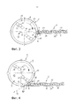
Так, согласно изобретению, кроме того, предусмотрено, что радиальное расстояние mb инструмента, измеренное от радиально крайней точки ближайшего к дну смесительного и/или измельчающего инструмента, или инструмента, и/или ножа, или от описываемой этой точкой окружности до внутренней поверхности боковой стенки бункера, составляет от 15 до 120 мм, преимущественно от 20 до 80 мм.Thus, according to the invention, it is further provided that the radial distance mb of the tool, measured from the radially extreme point of the mixing and / or grinding tool closest to the bottom, or tool, and / or knife, or from the circumference described by this point to the inner surface of the side wall hopper, is from 15 to 120 mm, mainly from 20 to 80 mm.
Кроме того, радиальное расстояние mb соответствует отношениюIn addition, the radial distance mb corresponds to the ratio
mb=k·DB,mb = k · D B ,
где DB - внутренний диаметр в мм бункера в форме кругового цилиндра или внутренний диаметр в мм пересчитанного на ту же вместимость виртуального бункера в форме кругового цилиндра такой же высоты, k - постоянная или коэффициент в диапазоне 0,006-0,16.where D B is the inner diameter in mm of the hopper in the form of a circular cylinder or the inner diameter in mm calculated for the same capacity of the virtual hopper in the form of a circular cylinder of the same height, k is a constant or a coefficient in the range of 0.006-0.16.
Расстояние инструментов до стенки бункера должно предпочтительно поддерживаться небольшим, поскольку это улучшает характер питания и позволяет избежать «защемления» материала при затягивании. Тем не менее, должны соблюдаться достаточные допустимые расстояния. Если расстояние слишком велико, то это приводит к ухудшению загрузки.The distance of the tools to the hopper wall should preferably be kept small, as this improves the feeding pattern and avoids “pinching” of the material when tightened. However, sufficient allowable distances must be observed. If the distance is too large, this leads to poor loading.
Неожиданным оказалось то, что за счет вызванного встречным направлением вращения смесительных инструментов щадящего характера набивки в режущем уплотнителе могут использоваться более агрессивные инструменты, которые вводят в материал больше энергии. Следовательно, режущий уплотнитель может эксплуатироваться при более высокой температуре, что, в свою очередь, вызывает лучшую однородность при сокращении времени пребывания. Согласно изобретению, особенно хороший и эффективный ввод энергии происходит за счет особых соотношений расстояний в комбинации с обратным направлением вращения инструментов.Unexpectedly, due to the gentle rotation of the mixing tools caused by the opposite direction of the mixing tools, more aggressive tools can be used in the cutting sealant that introduce more energy into the material. Therefore, the cutting seal can be operated at a higher temperature, which, in turn, causes better uniformity while reducing residence time. According to the invention, a particularly good and efficient energy input occurs due to special distance ratios in combination with the reverse direction of rotation of the tools.
К тому же такая комбинация из режущего уплотнителя и экструдера неожиданно вызывает повышение производительности расплавления материала в присоединенном экструдере, поскольку в шнек поступают уже сильно подогретые частицы. За счет этого выравниваются возможные неоднородности, а поступающий из бункера в корпус шнека и затем уплотненный и расплавленный материал имеет высокую термическую и механическую однородность. За счет этого очень высоким является также конечное качество пластификата или агломерата на конце шнека экструдера или агломерирующего шнека, при этом могут использоваться шнеки, которые за счет предварительной обработки и подачи полимера щадящим образом обрабатывают его и вводят в него особенно мало мощности сдвига, чтобы расплавить его.Moreover, such a combination of a cutting sealant and an extruder unexpectedly causes an increase in the melting capacity of the material in the attached extruder, since already very heated particles enter the screw. Due to this, possible heterogeneities are smoothed out, and the material coming from the hopper into the screw housing and then the compacted and molten material has high thermal and mechanical uniformity. Due to this, the final quality of the plasticizer or agglomerate at the end of the screw of the extruder or agglomerating screw is also very high. In this case, screws can be used which, due to the preliminary processing and supply of the polymer, process it gently and introduce especially little shear power into it to melt it .
Кроме того, постоянство расхода по времени выше или пропускная способность более равномерная, а затягивание работает надежно без проблем при наполнении шнека.In addition, the constant flow rate over time or throughput is more uniform, and tightening works reliably without problems when filling the screw.
Другие предпочтительные варианты осуществления изобретения описаны следующими признаками.Other preferred embodiments of the invention are described by the following features.
Согласно одному предпочтительному варианту, предусмотрено, что в бункере с возможностью вращения вокруг оси вращения установлен, по меньшей мере, один инструментодержатель, на/в котором расположен/расположены или выполнен/выполнены смесительный/смесительные и/или измельчающий/измельчающие инструмент/инструменты.According to one preferred embodiment, it is provided that at least one tool holder is mounted in the hopper with the possibility of rotation around the axis of rotation on which the mixing / mixing and / or grinding / grinding tools / tools are located / arranged / made / made.
Предпочтительно, если инструментодержатель представляет собой расположенный, в частности, параллельно дну несущий диск. На нем могут легко и просто монтироваться инструменты.Preferably, the tool holder is a carrier disk located, in particular, parallel to the bottom. Tools can be mounted on it easily and simply.
В этой связи предпочтительно, если смесительный и/или измельчающий инструмент и/или инструментодержатель включает в себя инструменты и/или ножи, которые в направлении вращения или движения оказывают на полимерный материал измельчающее, режущее и/или нагревающее действие.In this regard, it is preferable if the mixing and / or grinding tool and / or tool holder includes tools and / or knives that, in the direction of rotation or movement, exert a grinding, cutting and / or heating effect on the polymer material.
Вариант, в котором ножи очень просто заменять, предусматривает, что смесительный и/или измельчающий инструмент, или инструменты, и/или ножи расположены или выполнены на верхней стороне инструментодержателя.A variant in which the knives are very easy to replace provides that the mixing and / or grinding tool, or tools and / or knives are located or are made on the upper side of the tool holder.
Предпочтительным образом может быть также предусмотрено, что инструменты и/или ножи расположены, разъемно закреплены или выполнены на лежащей радиально дальше всего наружу, направленной к внутренней поверхности боковой стенки, в большинстве случаев вертикальной внешней кромке инструментодержателя.Advantageously, it can also be provided that the tools and / or knives are positioned, detachably fixed or formed on the outermost radially outwardly directed toward the inner surface of the side wall, in most cases the vertical outer edge of the tool holder.
В одном предпочтительном варианте предусмотрено, что радиальное расстояние mc инструментодержателя, измеренное от радиально крайней точки ближайшего к дну инструментодержателя или от описываемой этой точкой окружности до внутренней поверхности боковой стенки бункера, составляет от 30 до 210 мм, преимущественно от 40 до 150 мм.In one preferred embodiment, it is provided that the radial distance mc of the tool holder, measured from the radially extreme point closest to the bottom of the tool holder or from the circle described by this point to the inner surface of the side wall of the hopper, is from 30 to 210 mm, preferably from 40 to 150 mm.
Особенно предпочтительно, если соотношение между внутренним диаметром DB бункера и диаметром DW описываемой радиально крайней точкой ближайшего к дну инструментодержателя окружности отвечает следующему отношению:It is particularly preferable if the ratio between the inner diameter D B of the hopper and the diameter D W of the described radially extreme point of the circle closest to the bottom of the tool holder corresponds to the following relation:
DB=k2·DW,D B = k 2 · D W ,
где DB - внутренний диаметр бункера в мм, DW - диаметр описываемой радиально крайней точкой инструментодержателя окружности в мм, а k2 - постоянная или коэффициент в диапазоне от 1,01 до 1,5.where D B is the inner diameter of the hopper in mm, D W is the diameter of the circle described by the radially extreme point of the tool holder in mm, and k 2 is a constant or coefficient in the range from 1.01 to 1.5.
Согласно одному предпочтительному варианту, предусмотрено, что постоянная k2 у бункеров с внутренним диаметром DB≥1300 мм составляет от 1,01 до 1,12. Здесь воздействие инструментов оказалось особенно эффективным, а расход может поддерживаться очень постоянным.According to one preferred embodiment, it is provided that the constant k 2 for bins with an inner diameter of D B ≥1300 mm is from 1.01 to 1.12. Here, the impact of the tools turned out to be especially effective, and the flow rate can be kept very constant.
Предпочтительным образом предусмотрено, что радиальное расстояние mc инструментодержателя больше или равно радиальному расстоянию mb инструмента. Выступающие или отстоящие за счет этого от инструментодержателя инструменты дополнительно способствуют воздействию на материал.Preferably, it is provided that the radial distance mc of the tool holder is greater than or equal to the radial distance mb of the tool. The tools protruding or spaced apart from the tool holder further contribute to the impact on the material.
Согласно одному предпочтительному варианту, предусмотрено, что транспортер расположен на приемном бункере так, что скалярное произведение вектора направления (вектора направления вращения), ориентированного по касательной к окружности, описываемой радиально крайней точкой смесительного и/или измельчающего инструмента, или к проходящему мимо отверстия полимерному материалу и перпендикулярно радиали приемного бункера и указывающего в направлении вращения и/или движения смесительного и/или измельчающего инструмента, и вектора направления транспортировки транспортера в каждой отдельной точке или во всей зоне отверстия или в каждой отдельной точке или во всей зоне непосредственно радиально перед отверстием равно нулю или отрицательное. Зона непосредственно радиально перед отверстием определяется как та зона перед отверстием, в которой материал находится вплотную перед самым прохождением через отверстие, но еще не прошел через него. Таким образом, достигаются упомянутые выше преимущества и эффективно предотвращаются любые вызванные эффектами набивки образования агломератов в зоне питающего отверстия. В частности, речь не идет при этом также о пространственном расположении смесительных инструментов и шнека по отношению друг к другу, а, например, ось вращения не должна быть ориентирована перпендикулярно к дну или к продольной оси транспортера или шнека. Реверсирование направления вращения и вектор направления транспортировки лежат в одной, преимущественно горизонтальной, плоскости или в плоскости, ориентированной перпендикулярно оси вращения.According to one preferred embodiment, it is provided that the conveyor is located on the receiving hopper so that the scalar product of the direction vector (direction vector of rotation) oriented tangentially to the circle described by the radially extreme point of the mixing and / or grinding tool, or to the polymer material passing through the holes and perpendicular to the radial of the receiving hopper and pointing in the direction of rotation and / or movement of the mixing and / or grinding tool, and the direction vector If the conveyor is transported at each individual point or in the entire area of the hole or in each separate point or in the entire area immediately radially in front of the hole, it is zero or negative. The zone immediately radially in front of the hole is defined as that zone in front of the hole in which the material is right before it passes through the hole, but has not yet passed through it. Thus, the above advantages are achieved and any agglomerate formation caused by the effects of the packing is effectively prevented in the area of the feed opening. In particular, we are not talking about the spatial arrangement of the mixing tools and the screw with respect to each other, but, for example, the axis of rotation should not be oriented perpendicular to the bottom or to the longitudinal axis of the conveyor or screw. The reversal of the direction of rotation and the vector of the direction of transportation lie in one, mainly horizontal, plane or in a plane oriented perpendicular to the axis of rotation.
Другой предпочтительный вариант возникает за счет того, что вектор направления вращения смесительного и/или измельчающего инструмента заключает с вектором направления транспортировки транспортера угол ≥90°≤180°, причем угол в точке пересечения обоих векторов направления измеряется на лежащем вверх по потоку относительно направления вращения или движения краю отверстия, в частности в наиболее удаленной вверх по потоку точке на этом краю или отверстии. За счет этого описан тот угловой диапазон, в котором транспортер должен быть расположен на приемном бункере для достижения предпочтительных эффектов. При этом во всей зоне отверстия или в каждой его точке происходит, по меньшей мере, незначительная встречная ориентация действующих на материал усилий или, в крайнем случае, нейтральная в отношении давления поперечная ориентация. Ни в одной точке отверстия скалярное произведение векторов направления смесительных инструментов и шнека не является положительным, даже на участке отверстия не возникает тем самым слишком большого действия набивки.Another preferred option arises due to the fact that the vector of the direction of rotation of the mixing and / or grinding tool encloses an angle of ≥90 ° ≤180 ° with the conveyor vector of the conveyor, and the angle at the intersection of both direction vectors is measured on the upstream relative to the direction of rotation or movement of the edge of the hole, in particular at the point farthest upstream on that edge or hole. Due to this, the angular range in which the conveyor should be located on the receiving hopper to achieve the preferred effects is described. At the same time, at least a slight counter orientation of the forces acting on the material or, in extreme cases, a pressure-neutral transverse orientation occurs in the entire zone of the hole or at each of its points. At any point in the hole, the scalar product of the direction vectors of the mixing tools and the screw is not positive, even in the area of the hole, too much packing action does not occur.
В другом предпочтительном варианте осуществления изобретения предусмотрено, что вектор направления вращения или движения заключает с вектором направления транспортировки угол от 170 до 180°, измеренный в точке пересечения обоих векторов направления в середине отверстия. Такое расположение оправдано в том случае, если транспортер расположен на режущем уплотнителе по касательной.In another preferred embodiment of the invention, it is provided that the vector of the direction of rotation or movement encloses with the vector of the direction of transportation an angle of 170 to 180 ° measured at the intersection of both direction vectors in the middle of the hole. This arrangement is justified if the conveyor is located tangentially on the cutting seal.
Чтобы предотвратить возникновение слишком большого действия набивки, может быть предпочтительно предусмотрено, что расстояние или смещение продольной оси от радиали больше или равно половине внутреннего диаметра корпуса транспортера или шнека.To prevent the occurrence of too much action of the packing, it can preferably be provided that the distance or offset of the longitudinal axis from the radial is greater than or equal to half the inner diameter of the conveyor housing or screw.
Далее в этом смысле может быть предпочтительным рассчитать расстояние или смещение продольной оси от радиали ≥7%, еще предпочтительнее ≥20% радиуса приемного бункера. У транспортеров с удлиненной зоной питания или шлицевой втулкой или расширенным карманом предпочтительно это расстояние или смещение больше или равно радиусу приемного бункера. В частности, это относится к тем случаям, когда транспортер присоединен по касательной к приемному бункеру или проходит по касательной к его сечению.Further in this sense, it may be preferable to calculate the distance or offset of the longitudinal axis from the radial of ≥7%, even more preferably ≥20% of the radius of the receiving hopper. For conveyors with an elongated feed zone or spline sleeve or extended pocket, this distance or offset is preferably greater than or equal to the radius of the receiving hopper. In particular, this applies to those cases when the conveyor is connected tangentially to the receiving hopper or passes tangentially to its cross section.
При этом, в частности, предпочтительно, если продольная ось транспортера или шнека, или продольная ось ближайшего к зоне питания шнека, или внутренняя стенка корпуса, или огибающая шнека проходит по касательной к внутренней стороне боковой стенки бункера, причем шнек преимущественно соединен на своей торцевой стороне с приводом, а на своем противоположном торцевом конце транспортирует материал к расположенному на торцевом конце корпуса выходному отверстию, в частности головке экструдера.In this case, in particular, it is preferable if the longitudinal axis of the conveyor or screw, or the longitudinal axis of the screw closest to the feed zone, or the inner wall of the housing, or the envelope of the screw passes tangentially to the inner side of the side wall of the hopper, and the screw is mainly connected on its end side with a drive, and at its opposite end end transports the material to the outlet located on the end end of the housing, in particular the extruder head.
В случае радиально смещенных, однако расположенных не по касательной транспортеров предпочтительно предусмотрено, что воображаемое продолжение продольной оси транспортера против направления транспортировки проходит через внутреннее пространство приемного бункера, по меньшей мере, на отдельных участках в виде секущей.In the case of conveyors radially displaced, but located not tangentially, it is preferably provided that an imaginary extension of the conveyor longitudinal axis against the direction of conveyance passes through the interior of the receiving hopper, at least in separate sections as a secant.
Предпочтительно предусмотрено, что отверстие непосредственно и напрямую и без большого промежутка или передающего участка, например транспортирующего шнека, соединено с питающим отверстием. Таким образом, возможна эффективная и щадящая передача материала.Preferably, it is provided that the hole is directly and directly and without a large gap or transmitting portion, such as a conveying screw, connected to the feed hole. Thus, an efficient and gentle material transfer is possible.
Реверсирование направления вращения смесительных и измельчающих инструментов в бункере не может происходить ни в коем случае произвольно или по ошибке, и ни в известных устройствах, ни в предложенном устройстве нельзя просто так заставить вращаться смесительные инструменты во встречном направлении, в частности, также потому, что смесительные и измельчающие инструменты определенным образом расположены асимметрично или ориентированными по направлению так, что они действуют только на одну сторону или в одном направлении. Если удалось бы придать такому агрегату вращение в неправильном направлении, то тогда не образовался бы хороший тромб, достаточно не измельчился бы или не нагрелся материал. Любой режущий уплотнитель имеет тем самым жестко заданное направление вращения смесительных и измельчающих инструментов.The reversal of the direction of rotation of the mixing and grinding tools in the hopper can never happen arbitrarily or by mistake, and neither in the known devices, nor in the proposed device can you just make the mixing tools rotate in the opposite direction, in particular, also because the mixing and the grinding tools are in a certain way positioned asymmetrically or oriented in a direction such that they act only on one side or in one direction. If it were possible to give such an aggregate rotation in the wrong direction, then a good blood clot would not have formed, the material would not have been sufficiently crushed or heated. Any cutting sealant thus has a strictly defined direction of rotation of the mixing and grinding tools.
В этой связи особенно предпочтительно, если воздействующие на полимерный материал, указывающие в направлении вращения или движения передние участки или передние кромки смесительных и/или измельчающих инструментов по-разному выполнены, искривлены, установлены или расположены по сравнению с задними или догоняющими в направлении вращения или движения участками.In this regard, it is particularly preferable if the front sections or leading edges of the mixing and / or grinding tools acting on the polymeric material, indicating in the direction of rotation or movement, are differently formed, curved, installed or arranged in comparison with the rear or catching in the direction of rotation or movement plots.
Инструменты и/или ножи могут закрепляться непосредственно на валу или располагаться преимущественно на расположенном, в частности, параллельно дну вращающемся инструментодержателе или на несущем диске, или выполняться в нем, или отформовываться на нем, при необходимости, за одно целое.Tools and / or knives can be mounted directly on the shaft or can be located mainly on the rotating tool holder located on, in particular, parallel to the bottom or on the carrier disk, or run in it, or molded on it, if necessary, in one piece.
В принципе, упомянутые эффекты являются существенными не только для компрессионных экструдеров или агломераторов, но и для некомпрессионных или малокомпрессионных транспортирующих шнеков. Также в этом случае предотвращаются локальные переполнения.In principle, these effects are significant not only for compression extruders or agglomerators, but also for non-compression or light compression conveying screws. Also in this case, local overflows are prevented.
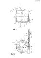
В другом, особенно предпочтительном варианте предусмотрено, что приемный бункер выполнен, в основном, цилиндрическим с плоским дном и ориентированной вертикально к нему боковой стенкой в форме боковой поверхности цилиндра. Конструктивно просто далее, если ось вращения совпадает с центральной средней осью приемного бункера. В другом предпочтительном варианте предусмотрено, что ось вращения или центральная средняя ось бункера ориентирована вертикально и/или перпендикулярно дну. За счет этой особой геометрии в устройстве со стабильной и конструктивно простой конструкцией оптимизирован характер питания.In another particularly preferred embodiment, it is provided that the receiving hopper is made essentially cylindrical with a flat bottom and a side wall oriented vertically to it in the form of a side surface of the cylinder. Structurally, simply further, if the axis of rotation coincides with the central middle axis of the receiving hopper. In another preferred embodiment, it is provided that the axis of rotation or the central middle axis of the hopper is oriented vertically and / or perpendicular to the bottom. Due to this special geometry, the nature of the power supply is optimized in a device with a stable and structurally simple design.
В этой связи также предпочтительно предусмотреть, чтобы смесительный и/или измельчающий инструмент или в случае нескольких расположенных друг над другом смесительных и/или измельчающих инструментов самый нижний, ближайший к дну смесительный и/или измельчающий инструмент и отверстие располагались на небольшом расстоянии от дна, в частности в зоне самой нижней четверти высоты приемного бункера. При этом расстояние определяется и измеряется от самой нижней кромки отверстия или питающего отверстия до дна бункера в зоне края последнего. Поскольку угловая кромка выполнена в большинстве случаев закругленной, расстояние измеряется от самой нижней кромки отверстия вдоль воображаемых продолжений боковой стенки вниз до воображаемого продолжения дна бункера наружу. Подходящие расстояния составляют от 10 до 400 мм.In this regard, it is also preferable to provide that the mixing and / or grinding tool, or in the case of several mixing and / or grinding tools located one above the other, the lowest mixing and / or grinding tool closest to the bottom and the opening should be located at a small distance from the bottom, in in particular in the area of the lowest quarter of the height of the receiving hopper. In this case, the distance is determined and measured from the lowest edge of the hole or feed hole to the bottom of the hopper in the region of the edge of the latter. Since the corner edge is rounded in most cases, the distance is measured from the lowest edge of the hole along the imaginary extensions of the side wall down to the imaginary extension of the bottom of the hopper out. Suitable distances are from 10 to 400 mm.
Бункер необязательно должен иметь форму кругового цилиндра, хотя такая форма является предпочтительной по практическим и технологическим соображениям. Вместимость отличающихся от формы кругового цилиндра бункеров, например бункеров в форме усеченного конуса или цилиндрических бункеров эллиптической или овальной в плане формы, следует пересчитать равной вместимости бункеров в форме кругового цилиндра, предположив, что высота этого условного бункера равна его диаметру. Высота бункеров, существенно превышающая образующийся тромб (с учетом безопасного расстояния), остается неучтенной, поскольку такая чрезмерная высота не используется и поэтому не оказывает больше никакого влияния на переработку материала.The hopper need not have the shape of a circular cylinder, although this shape is preferred for practical and technological reasons. The capacity of silos that are different from the shape of a circular cylinder, for example truncated cone-shaped silos or elliptical or oval cylindrical silos in terms of shape, should be recalculated to be equal to the capacity of circular-shaped silos, assuming that the height of this conditional silo is equal to its diameter. The height of the bunkers, significantly exceeding the thrombus formed (taking into account the safe distance), remains unaccounted for, since such an excessive height is not used and therefore no longer has any effect on the processing of the material.
Под термином «транспортер» следует понимать в данном случае как установки с некомпрессионными или декомпрессионными шнеками, т.е. чисто транспортирующими шнеками, так и установки с компрессионными шнеками, т.е. шнеки экструдеров агломерирующего или пластифицирующего действия.The term "conveyor" should be understood in this case as installations with non-compression or decompression augers, i.e. purely conveying augers, and installations with compression augers, i.e. extruder screws of agglomerating or plasticizing action.
Под терминами «экструдер» и «шнек экструдера» в данном случае следует понимать как экструдеры и шнеки, с помощью которых материал полностью или частично расплавляется, так и экструдеры, с помощью которых размягченный материал лишь агломерируется, однако не расплавляется. В случае агломерирующих шнеков материал лишь на короткое время сильно уплотняется и режется, но не пластифицируется. Поэтому агломерирующий шнек выдает на своем выходе материал, который полностью не расплавлен, а состоит из оплавленных лишь на своей поверхности частиц, которые как бы спечены. Однако в обоих случаях шнек оказывает давление на материал и уплотняет его.The terms "extruder" and "extruder screw" in this case should be understood as extruders and screws, with which the material is completely or partially melted, and extruders, with which the softened material only agglomerates, but does not melt. In the case of agglomerating augers, the material is only very briefly compacted and cut, but not plasticized. Therefore, the agglomerating screw gives out at its outlet a material that is not completely molten, but consists of particles melted only on its surface, which are as if sintered. However, in both cases, the auger exerts pressure on the material and compacts it.
В представленных примерах описаны только экструдеры с единственным шнеком, например одновальные или одношнековые экструдеры. Однако в качестве альтернативы возможны также транспортеры более чем с одним шнеком, например двух- или многовальные транспортеры или экструдеры, в частности, с несколькими одинаковыми шнеками, имеющими, по меньшей мере, одинаковые диаметры d.In the examples presented, only single screw extruders are described, for example single or single screw extruders. However, as an alternative, conveyors with more than one screw are also possible, for example double or multi-shaft conveyors or extruders, in particular with several identical screws having at least the same diameters d.
Другие признаки и преимущества изобретения приведены в описании нижеследующих примеров осуществления его объекта, которые не следует понимать как ограничивающие его и которые схематично и не в масштабе изображены на чертежах, на которых:Other features and advantages of the invention are given in the description of the following examples of implementation of its object, which should not be construed as limiting it and which are schematically and not to scale shown in the drawings, in which:
фиг. 1 - сечение устройства с присоединенным приблизительно по касательной экструдером;FIG. 1 is a sectional view of a device with an extruder connected approximately tangentially;
фиг. 2 - разрез варианта из фиг. 1;FIG. 2 is a sectional view of the embodiment of FIG. one;
фиг. 3 - другой вариант с минимальным смещением;FIG. 3 - another option with minimal displacement;
фиг. 4 - другой вариант с большим смещением;FIG. 4 - another option with a large offset;
фиг. 5 и 6 - результаты испытаний.FIG. 5 and 6 are test results.
Ни бункеры, ни шнеки или смесительные инструменты не показаны в масштабе ни как таковые, ни в соотношении между собой. Так, например, в действительности бункеры в большинстве случаев больше или шнеки длиннее, чем показано.Neither the bins nor the augers or mixing tools are shown on a scale either as such or in relation to each other. So, for example, in reality, the bins in most cases are larger or the screws are longer than shown.
Изображенная на фиг. 1 и 2 предпочтительная комбинация режущего уплотнителя и экструдера для подготовки или рециклирования полимерного материала содержит бункер или режущий уплотнитель или разрыватель 1 в форме кругового цилиндра с плоским горизонтальным дном 2 и ориентированной перпендикулярно к нему, вертикальной боковой стенкой 9 в форме боковой поверхности цилиндра.Depicted in FIG. 1 and 2, a preferred combination of a cutting seal and an extruder for preparing or recycling the polymeric material comprises a hopper or cutting seal or tear-off 1 in the form of a circular cylinder with a flat horizontal bottom 2 and oriented vertically to it, a
На небольшом расстоянии от дна 2, максимум в пределах от 10 до 20%, при необходимости, менее высоты боковой стенки 9, измеренном от дна 2 до ее самого верхнего края, расположен ориентированный параллельно дну плоский несущий диск или инструментодержатель 13, который вращается вокруг центральной оси 10 вращения, являющейся одновременно центральной средней осью бункера 1, в обозначенном стрелкой направлении 12 вращения или движения. Несущий диск 13 приводится во вращение двигателем 21, находящимся под бункером 1. На верхней стороне несущего диска 13 расположены ножи или инструменты, например режущие ножи 14, которые вместе с ним образуют смесительный и/или измельчающий инструмент 3.At a small distance from the bottom 2, a maximum ranging from 10 to 20%, if necessary, less than the height of the
Как схематично показано, ножи 14 расположены на несущем диске 13 не симметрично, а на своих указывающих в направлении 12 вращения или движения передних кромках 22 выполнены, установлены или расположены по-особому, с возможностью механического воздействия на полимерный материал характерным образом. Радиально крайние кромки смесительных и/или измельчающих инструментов 3 подходят относительно близко, примерно на 5% радиуса 11 бункера 1, к внутренней поверхности боковой стенки 9.As shown schematically, the
Бункер 1 имеет вверху загрузочное отверстие, через которое в бункер 1, например, посредством транспортирующего устройства, по указанной стрелке загружается перерабатываемый материал, например порции полимерных пленок. В качестве альтернативы может быть предусмотрено, что контейнер 1 закрыт и воздух откачивается из него, по меньшей мере, до технического вакуума, причем материал загружается через шлюзовую систему. Этот материал захватывается вращающимися смесительными и/или измельчающими инструментами 3 и завихряется в виде тромба 30, причем материал поднимается вверх вдоль вертикальной боковой стенки 9, а затем приблизительно в зоне активной высоты Η бункера 1 под действием силы тяжести снова падает внутрь и вниз в зону его середины. Активная высота Η бункера 1 приблизительно равна его внутреннему диаметру D. Следовательно, в бункере 1 образуется тромб, материал которого завихряется как сверху вниз, так и в направлении 12 вращения. Тем самым такое устройство вследствие особого расположения смесительных и измельчающих инструментов 3 или ножей 14 может эксплуатироваться только с заданным направлением 12 вращения или движения, а направление 12 вращения нельзя реверсировать просто так или без дополнительных изменений.The hopper 1 has a loading hole at the top through which through the indicated hopper 1, for example, by means of a conveying device, the processed material, for example, portions of polymer films, is loaded. Alternatively, it can be provided that the container 1 is closed and air is pumped out of it at least to a technical vacuum, the material being loaded through a lock system. This material is captured by rotating mixing and / or grinding
Загруженный полимерный материал измельчается смесительными и измельчающими инструментами 3, смешивается и при этом за счет введенной механической энергии трения нагревается и размягчается, однако не расплавляется. После определенного времени пребывания в бункере 1 гомогенизированный, размягченный, тестообразный, но не расплавленный материал выгружается из бункера 1 через отверстие 8, подается в зону питания экструдера 5, захватывается там шнеком 9 и расплавляется, что подробно поясняется ниже.The loaded polymer material is crushed by mixing and grinding
На высоте единственного в данном случае измельчающего и смесительного инструмента 3 в боковой стенке 9 бункера 1 выполнено упомянутое отверстие 8, через которое из бункера 1 выгружается предварительно обработанный полимерный материал. Он передается на расположенный по касательной на бункере 1 одношнековый экструдер 5, причем его корпус 16 имеет в своей боковой стенке питающее отверстие 80 для захватываемого шнеком 6 материала. Такой вариант имеет то преимущество, что шнек 6 может приводиться во вращение от нижнего согласно чертежу торцевого конца схематично показанным приводом, так что верхний согласно чертежу торцевой конец шнека 6 может быть свободен от привода. Это позволяет расположить на этом верхнем торцевом конце выходное отверстие для подаваемого шнеком 6 пластифицированного или агломерированного полимерного материала, например, в виде головки экструдера (не показана). Поэтому полимерный материал, не отклоняясь шнеком 6, может подаваться через выходное отверстие, что невозможно осуществлять в вариантах, представленных на фиг. 3 и 4.At the height of the only grinding and mixing
Питающее отверстие 80 связано по подаче или передаче материала с отверстием 8 и в данном случае напрямую, непосредственно и без длинной промежуточной детали. Предусмотрена лишь очень короткая зона передачи.The
В корпусе 16 с возможностью вращения вокруг своей продольной оси 15 установлен компрессионный шнек 6. Продольная ось 15 шнека 6 и экструдера 5 совпадают. Экструдер 5 подает материал в направлении стрелки 17. Экструдер 5 представляет собой известный сам по себе традиционный экструдер, в котором размягченный полимерный материал уплотняется и за счет этого расплавляется, а расплав выходит затем с противоположной стороны на головке экструдера.In the
Смесительные и/или измельчающие инструменты 3 или ножи 14 лежат почти на той же высоте или в той же плоскости, что и центральная продольная ось 15 экструдера 5. Крайние концы ножей 14 достаточно отстоят от гребней шнека 6.Mixing and / or grinding
Как уже сказано, в варианте, представленном на фиг. 1 и 2, экструдер 5 присоединен по касательной к бункеру 1 или проходит по касательной к его сечению. Воображаемое продолжение центральной продольной оси 15 экструдера 5 или шнека 6 против направления 17 транспортировки экструдера 5 назад проходит на чертеже мимо оси 10 вращения, не пересекая ее. Продольная ось 15 экструдера 5 или шнека 6 смещена со стороны выхода на расстояние 18 относительно радиали 11 бункера 1, которая параллельна продольной оси 15 и направлена наружу от оси 10 вращения смесительного и/или измельчающего инструмента 3 в направлении 17 транспортировки экструдера 5. В данном случае воображаемое продолжение назад продольной оси 15 экструдера 5 не проходит через внутреннее пространство бункера 1, а проходит вплотную мимо него.As already mentioned, in the embodiment shown in FIG. 1 and 2, the
Расстояние 18 немного больше радиуса бункера 1. Экструдер 5 смещен тем самым незначительно наружу, или зона питания немного глубже.The
Под термином «встречно направленный», «встречный» или «противоположный» следует понимать здесь любую ориентацию векторов по отношению друг к другу не под острым углом, как это подробно поясняется ниже.The term “counter directional”, “counter” or “opposite” should be understood here to mean any orientation of the vectors relative to each other not at an acute angle, as is explained in detail below.
Иначе говоря, скалярное произведение вектора 19 направления 12 вращения, который ориентирован по касательной к окружности, описываемой крайней точкой смесительного и/или измельчающего инструмента 3, или по касательной к проходящему мимо отверстия 8 материалу и который указывает в направлении 12 вращения или движения смесительных и/или измельчающих инструментов 3, и вектора 17 направления транспортировки экструдера 5, проходящего в направлении транспортировки параллельно центральной продольной оси 15, в каждой отдельной точке отверстия 8 или в зоне радиально непосредственно перед отверстием 8 везде равно нулю или является отрицательным, но никогда положительным.In other words, the scalar product of the
У питающего отверстия на фиг. 1 и 2 скалярное произведение вектора 19 направления 12 вращения и вектора направления 17 транспортировки в каждой точке отверстия 8 отрицательное.At the supply opening in FIG. 1 and 2, the scalar product of the
Угол α между векторами 17 и 19, измеренный в наиболее удаленной вверх по потоку от направления 12 вращения точке 20 отверстия 8 или на наиболее удаленном вверх по потоку краю отверстия 8, составляет почти максимально около 170°.The angle α between
Если переместиться вдоль отверстия 8 дальше вниз, т.е. в направлении 12 вращения, то тупой угол α будет увеличиваться. В середине отверстия 8 угол между векторами направлений составляет около 180°, а скалярное произведение максимально отрицательное, дальше влево угол становится даже больше 180°, а скалярное произведение снова немного уменьшается, однако остается всегда отрицательным. Однако эти углы больше не называются углами α, поскольку они не измерены в точке 20.If you move along the
Не показанный на фиг. 2, измеренный в середине или в центре отверстия 8 угол β между вектором 19 направления 12 вращения и вектором 17 направления транспортировки составляет от 178 до 180°.Not shown in FIG. 2, measured in the middle or in the center of the
Устройство, представленное на фиг. 2, представляет собой первый предельный случай или экстремальное значение. При таком расположении возможно очень щадящее действие набивки, или возможна очень предпочтительная загрузка, и такое устройство предпочтительно, в частности, для восприимчивых материалов, обрабатываемых близко к области плавления, или для длиннополосного материала.The device shown in FIG. 2, represents the first limiting case or extreme value. With this arrangement, a very gentle action of the packing is possible, or a very preferable loading is possible, and such a device is preferable, in particular, for susceptible materials being processed close to the melting region, or for long-strip material.
Радиальное расстояние mb инструмента, измеренное от радиально крайней точки, или от лежащего дальше всего наружу острия ножа 14, или от описываемой им окружности до внутренней поверхности боковой стенки 9 бункера 1, обозначено на фиг. 2 в качестве примера. Оно соответствует отношению mb=k·DB.The radial distance mb of the tool, measured from the radially extreme point, or from the tip of the
Точно так же обозначено радиальное расстояние mc инструмента, измеренное от радиально крайней точки круглого несущего диска 13 до внутренней поверхности боковой стенки 9 бункера 1. Оно соответствует отношению DB=k2·DW.The radial distance mc of the tool, measured from the radially extreme point of the
Расстояние mc больше расстояния mb, т.е. инструменты или ножи 14 выступают или выдаются за несущий диск 13.The distance mc is greater than the distance mb, i.e. tools or
На фиг. 3 и 4 расстояния mc и mb не обозначены. Эти чертежи служат, в первую очередь, для иллюстрации возможностей присоединения экструдера.In FIG. 3 and 4, the distances mc and mb are not indicated. These drawings serve primarily to illustrate the possibilities of connecting an extruder.
На фиг. 3 изображен альтернативный вариант, в котором экструдер 5 присоединен к бункеру 1 не по касательной, а своей торцевой стороной 7. Шнек 6 и корпус 16 экструдера 5 в зоне отверстия 8 приведены в соответствие с контуром внутренней стенки бункера 1 и заподлицо смещены назад. Ни одна часть экструдера 5 не проходит через отверстие 8 во внутреннее пространство бункера 1.In FIG. 3 shows an alternative embodiment in which the
Расстояние 18 соответствует здесь 5-10% радиуса 11 бункера 1 и примерно половине внутреннего диаметра d корпуса 16. Таким образом, этот вариант представляет собой второй предельный случай или экстремальное значение с минимально возможным смещением или расстоянием 18, когда направление 12 вращения или движения смесительных и/или измельчающих инструментов 3, по меньшей мере, незначительно встречно направлено направлению 17 транспортировки экструдера 5, а именно по всей площади сечения отверстия 8.The
На фиг. 3 скалярное произведение равно точно нулю в той наиболее удаленной вверх по потоку точке 20, которая лежит на наиболее удаленном вверх по потоку краю отверстия 8. Угол α между вектором направления 17 транспортировки и вектором 19 направления 12 вращения, измеренный в точке 20 на фиг. 3, составляет точно 90°. Если переместиться вдоль отверстия 8 дальше вниз, т.е. в направлении 12 вращения, то угол между векторами направлений будет увеличиваться и станет тупым углом, который больше 90°, а скалярное произведение будет одновременно отрицательным. Ни в одной точке или ни в одной зоне отверстия 8 скалярное произведение не является, однако, положительным, или угол не меньше 90°. За счет этого локальная избыточная загрузка не может произойти даже на одном участке отверстия 8 или ни в одной зоне отверстия 8 не может произойти опасного превышения действия набивки.In FIG. 3, the scalar product is exactly zero at that
В этом и заключается существенное отличие от чисто радиального расположения, поскольку точка 20 или кромка 20′ при радиальном расположении экструдера имела бы угол α меньше 90°, а зоны отверстия 8, лежащие согласно чертежу выше радиали 11, или вверх по потоку, или со стороны входа, имели бы положительное скалярное произведение. Следовательно, в этих зонах мог бы скапливаться локально расплавленный полимерный материал.This is a significant difference from a purely radial arrangement, since a
На фиг. 4 изображен другой альтернативный вариант, в котором экструдер 5 со стороны выхода смещен немного дальше, чем на фиг. 3, однако еще не по касательной, как на фиг. 1 и 2. В данном случае, как и на фиг. 3, воображаемое продолжение назад продольной оси 15 экструдера 5 проходит через внутреннее пространство бункера 1 по типу секущей. Вследствие этого при измерении в направлении периферии бункера 1 отверстие 8 шире, чем в варианте на фиг. 3. Также расстояние 18 соответственно больше, чем на фиг. 3, однако меньше радиуса 11. Угол α, измеренный в точке 20, составляет около 150°, благодаря чему по сравнению с фиг. 3 действие набивки уменьшается, что предпочтительнее для определенных восприимчивых полимеров. Правый от бункера 1 внутренний край или внутренняя стенка корпуса 16 примыкает к бункеру 1 по касательной, благодаря чему в отличие от фиг. 3 отсутствует тупая переходная кромка. В этой наиболее удаленной вниз по потоку точке отверстия 8, на фиг. 4 слева, угол составляет около 180°.In FIG. 4 depicts another alternative in which the
ПримерExample
Показано сравнительное испытание установки из уровня техники (фиг. 5) и предложенной установки (фиг. 6).A comparative test of the installation of the prior art (Fig. 5) and the proposed installation (Fig. 6) is shown.
Обе установки содержали режущий уплотнитель диаметром 1100 мм с присоединенным к нему по касательной экструдером (конструкция, в принципе, как на фиг. 1 и 2). Эксплуатационные параметры были одинаковыми. В качестве материала применялась неизмельченная полипропиленовая пленка.Both installations contained a cutting seal with a diameter of 1100 mm with an extruder connected tangentially to it (design, in principle, as in Figs. 1 and 2). Operational parameters were the same. The material used was an unmilled polypropylene film.
В отличие от известной установки в предложенной установке направление вращения инструментов в режущем уплотнителе было реверсировано, как на фиг. 2. Кроме того, расстояние выступающих за несущий диск инструментов до стенки было определено в 35 мм.In contrast to the known installation in the proposed installation, the direction of rotation of the tools in the cutting seal was reversed, as in FIG. 2. In addition, the distance of the tools protruding beyond the bearing disc to the wall was determined to be 35 mm.
Соответствующие нижние кривые обозначают крутящий момент режущего уплотнителя, отображающий работу резания и уплотнения.The corresponding lower curves indicate the torque of the cutting seal, showing the cutting and sealing work.
Соответствующие верхние кривые обозначают давление расплава перед фильтрующим устройством. Это давление отображает расход или его постоянство.The corresponding upper curves indicate the melt pressure in front of the filter device. This pressure represents the flow rate or its constancy.
Хорошо видно, что в установке из уровня техники постоянство расхода в зависимости от времени меньше, чем в предложенной системе. Кроме того, можно видеть, что в системе из уровня техники, по меньшей мере, один раз (примерно в 12:30) возникала проблема с наполнением шнека.It is clearly seen that in the installation of the prior art, the constancy of flow depending on time is less than in the proposed system. In addition, it can be seen that in the system of the prior art, at least once (at about 12:30) there was a problem with filling the screw.
Claims (19)
mb=k·DB,
где DB - внутренний диаметр бункера в форме кругового цилиндра или внутренний диаметр пересчитанного на ту же вместимость виртуального бункера в форме кругового цилиндра такой же высоты, мм, k - постоянная в диапазоне от 0,006 до 0,16.1. A device for pre-processing and subsequent transportation, plasticization or agglomeration of polymers, in particular thermoplastic polymer waste, for recycling, containing a hopper (1) for the processed material, and in the hopper (1) with the possibility of rotation around the axis (10) installed mixing and / or a grinding tool (3) for mixing, heating and, if necessary, grinding the polymer material, moreover, in the side wall (9) of the hopper (1) in the height zone of the mixing and / or grinding tool (3) or the mixing and / or grinding tool (3) closest to the bottom, a hole (8) is made through which the pre-treated polymer material is discharged from the hopper (1), at least one conveyor (5), in particular an extruder (5), is provided ), for receiving the pre-processed material with at least one rotatably installed in the housing (16), in particular a plasticizing or agglomerating screw (6), the housing (16) having on its end side (7) or its side wall nourishing about a hole (80) for the material captured by the screw (6), which is in communication with the hole (8), characterized in that, with an imaginary extension, the central longitudinal axis (15) of the conveyor (5) or the screw (6) closest to the feed hole (80) passes against the direction (17) of transporting the conveyor (5) past the axis (10) of rotation without crossing it, moreover, the longitudinal axis (15) of the conveyor (5) or the screw (6) closest to the feed hole (80) from the outlet side and in the direction ( 12) the rotation or movement of the mixing and / or grinding tool (3) is displaced by standing (18) from the radial line (11) of the hopper (1), which is parallel to the longitudinal axis (15) and directed outward from the axis (10) of rotation of the mixing and / or grinding tool (3) in the direction (17) of conveyor transport (5) wherein the radial distance (mb) of the tool, measured from the radial outermost point of the mixing and / or grinding tool closest to the bottom (3) or the tools and / or knives provided therein (14) or from the circumference described by this point to the inner surface of the side wall (9) hopper (1), is from 15 to 120 mm, mainly from 20 to 80 mm, and corresponds to the following ratio:
mb = k · D B ,
where D B is the inner diameter of the hopper in the form of a circular cylinder or the inner diameter of the virtual hopper counted for the same capacity in the form of a circular cylinder of the same height, mm, k is a constant in the range from 0.006 to 0.16.
DB=k2·DW,
где DB - внутренний диаметр бункера (1), мм, DW - диаметр описываемой радиально крайней точкой инструментодержателя (13) окружности, мм, а k2 - постоянная в диапазоне от 1,01 до 1,5.5. The device according to any one of paragraphs. 1-4, characterized in that the ratio between the inner diameter (D B ) of the hopper (1) and the diameter (D W ) described by the radial outermost point of the circle closest to the bottom of the tool holder (13) corresponds to the following relation:
D B = k 2 · D W ,
where D B is the inner diameter of the hopper (1), mm, D W is the diameter of the circle described by the radially extreme point of the tool holder (13), mm, and k 2 is a constant in the range from 1.01 to 1.5.
Applications Claiming Priority (3)
| Application Number | Priority Date | Filing Date | Title |
|---|---|---|---|
| ATA1501/2011 | 2011-10-14 | ||
| ATA1501/2011A AT512146B1 (en) | 2011-10-14 | 2011-10-14 | DEVICE FOR PREPARING PLASTIC MATERIAL |
| PCT/AT2012/050152 WO2013052980A1 (en) | 2011-10-14 | 2012-10-12 | Apparatus for processing plastic material |
Publications (2)
| Publication Number | Publication Date |
|---|---|
| RU2014119374A RU2014119374A (en) | 2015-11-20 |
| RU2582710C2 true RU2582710C2 (en) | 2016-04-27 |
Family
ID=47142835
Family Applications (1)
| Application Number | Title | Priority Date | Filing Date |
|---|---|---|---|
| RU2014119374/05A RU2582710C2 (en) | 2011-10-14 | 2012-10-12 | Device for processing polymer material |
Country Status (22)
| Country | Link |
|---|---|
| US (1) | US9296128B2 (en) |
| EP (1) | EP2766159B1 (en) |
| JP (1) | JP2014530131A (en) |
| KR (1) | KR101744267B1 (en) |
| CN (1) | CN103857505B (en) |
| AT (1) | AT512146B1 (en) |
| AU (1) | AU2012323809B2 (en) |
| BR (1) | BR112014008841B1 (en) |
| CA (1) | CA2851661C (en) |
| DE (1) | DE202012012573U1 (en) |
| DK (1) | DK2766159T3 (en) |
| ES (1) | ES2561721T3 (en) |
| HK (1) | HK1200763A1 (en) |
| HU (1) | HUE027085T2 (en) |
| MX (1) | MX344509B (en) |
| PL (1) | PL2766159T3 (en) |
| RU (1) | RU2582710C2 (en) |
| SI (1) | SI2766159T1 (en) |
| TW (1) | TWI501851B (en) |
| UA (1) | UA109962C2 (en) |
| WO (1) | WO2013052980A1 (en) |
| ZA (1) | ZA201402102B (en) |
Families Citing this family (15)
| Publication number | Priority date | Publication date | Assignee | Title |
|---|---|---|---|---|
| AT504709B1 (en) * | 2006-11-23 | 2008-09-15 | Erema | METHOD AND DEVICE FOR INTRODUCING ADDITIVES |
| AT511362B1 (en) | 2010-04-14 | 2014-01-15 | Erema | DEVICE FOR PREPARING PLASTIC MATERIAL |
| AT512212B1 (en) | 2011-10-14 | 2015-02-15 | Erema | DEVICE FOR PREPARING PLASTIC MATERIAL |
| AT512148B1 (en) | 2011-10-14 | 2015-02-15 | Erema | DEVICE FOR PREPARING PLASTIC MATERIAL |
| AT512207B1 (en) | 2011-10-14 | 2015-02-15 | Erema | DEVICE FOR PREPARING PLASTIC MATERIAL |
| AT512149B1 (en) | 2011-10-14 | 2015-02-15 | Erema | DEVICE FOR PREPARING PLASTIC MATERIAL |
| AT512145B1 (en) * | 2011-10-14 | 2015-02-15 | Erema | DEVICE FOR PREPARING PLASTIC MATERIAL |
| AT512209B1 (en) | 2011-10-14 | 2015-02-15 | Erema | DEVICE FOR PREPARING PLASTIC MATERIAL |
| AT512222B1 (en) | 2011-10-14 | 2015-02-15 | Erema | DEVICE FOR PREPARING PLASTIC MATERIAL |
| AT512208B1 (en) * | 2011-10-14 | 2015-02-15 | Erema | DEVICE FOR PREPARING PLASTIC MATERIAL |
| AT512223B1 (en) | 2011-10-14 | 2015-02-15 | Erema | DEVICE FOR PREPARING PLASTIC MATERIAL |
| AT512205B1 (en) * | 2011-10-14 | 2015-02-15 | Erema | DEVICE FOR PREPARING PLASTIC MATERIAL |
| TWI583448B (en) * | 2015-06-12 | 2017-05-21 | Chen-Ze Wang | Structure of finisher |
| CN107115933A (en) * | 2017-05-26 | 2017-09-01 | 王成志 | A kind of efficient pulverizing equipment for sheep raising corn |
| CN112339242A (en) * | 2020-10-20 | 2021-02-09 | 安徽高伟新材料科技有限公司 | Raw material particle lifting and conveying device for plastic sheet production |
Citations (5)
| Publication number | Priority date | Publication date | Assignee | Title |
|---|---|---|---|---|
| US5102326A (en) * | 1986-10-10 | 1992-04-07 | Helmut Bacher | Apparatus for processing synthetic plastics material |
| EP0911131A1 (en) * | 1997-10-17 | 1999-04-28 | Gamma Meccanica S.R.L. | Unit for feeding a screw extruder with shredded plastic material |
| EP1181141B1 (en) * | 1999-06-02 | 2002-10-16 | BACHER, Helmut | Device and method for preparing plastic material, in particular thermoplastic material |
| EP1273412A1 (en) * | 2001-07-02 | 2003-01-08 | Magma Trade di Mauro Magni & C.snc | Process and apparatus for the production of filled thermoplastic polymers |
| RU98971U1 (en) * | 2010-06-01 | 2010-11-10 | Государственное образовательное учреждение высшего профессионального образования "Дальневосточный государственный технический университет (ДВПИ имени В.В. Куйбышева)" | DEVICE FOR PROCESSING THERMOPLASTES |
Family Cites Families (63)
| Publication number | Priority date | Publication date | Assignee | Title |
|---|---|---|---|---|
| US2927007A (en) | 1957-04-17 | 1960-03-01 | Braunschweigische Maschb Ansta | Apparatus for the treatment of animal and vegetable materials |
| DE2224209C3 (en) | 1972-05-18 | 1982-12-30 | Buckau-Walther AG, 4048 Grevenbroich | Device for ejecting the dry, leached chips from a diffusion tower |
| SU536062A1 (en) | 1974-01-04 | 1976-11-25 | Научно-Исследовательский Конструкторско-Технологический Институт Шинной Промышленности | Device for grinding elastic polymeric materials |
| DE2839446C2 (en) | 1978-09-11 | 1980-09-25 | Thyssen Industrie Ag, 4300 Essen | Device for compacting and agglomerating plastic waste |
| AT368737B (en) | 1980-07-31 | 1982-11-10 | Oesterr Schiffswerften | DEVICE FOR PROCESSING THERMOPLASTIC PLASTIC MATERIAL |
| DE3231237A1 (en) | 1982-08-23 | 1984-02-23 | Dr. Herfeld GmbH & Co KG, 5982 Neuenrade | METHOD FOR COMPRESSING THERMOPLASTIC PLASTIC MATERIAL |
| AT375867B (en) * | 1983-04-27 | 1984-09-25 | Erema | DEVICE FOR PROCESSING THERMOPLASTIC PLASTIC MATERIAL |
| GB2145351A (en) | 1983-08-24 | 1985-03-27 | Howden James & Co Ltd | Pulverizer |
| AT385234B (en) | 1984-08-01 | 1988-03-10 | Paracon Extrusionstech Gmbh | DEVICE FOR PROCESSING THERMOPLASTIC PLASTIC MATERIAL |
| CH673105A5 (en) | 1987-08-18 | 1990-02-15 | Indupack Ag | |
| DE8716077U1 (en) | 1987-12-04 | 1988-02-11 | Plastmachines Gelderland, 8039 Puchheim, De | |
| GB2256830A (en) | 1991-01-23 | 1992-12-23 | Phillip Arthur Hadley | "recycling of scrap material" |
| JPH07112708B2 (en) * | 1991-05-02 | 1995-12-06 | ワイケイケイ株式会社 | Automatic conversion and supply device for colored molding material in injection molding machine |
| AT398772B (en) * | 1992-04-30 | 1995-01-25 | Erema | METHOD AND DEVICE FOR RECYCLING FUMED PLASTIC MATERIAL |
| DE59400703D1 (en) * | 1993-06-08 | 1996-10-24 | Helmuth Schulz | DEVICE FOR DEGASSING THERMOPLASTIC PLASTIC |
| AT400315B (en) | 1994-03-01 | 1995-12-27 | Bacher Helmut | Device for degassing a thermoplastic polymer |
| JPH07148736A (en) | 1993-11-30 | 1995-06-13 | Tomomichi Uchida | Breaking-off device of waste plastic material delivered from injection molder |
| US5783225A (en) * | 1993-12-21 | 1998-07-21 | Bacher; Helmut | Apparatus for processing thermoplastic synthetic plastics material |
| EP0735945B1 (en) | 1993-12-21 | 1997-04-02 | BACHER, Helmut | Device for processing thermoplastic materials |
| AT405726B (en) | 1995-04-11 | 1999-11-25 | Bacher Helmut | DEVICE FOR PROCESSING THERMOPLASTIC PLASTIC GOODS |
| ES2147940T3 (en) | 1995-11-11 | 2000-10-01 | Schafer Elektrotechnik Sonderm | PROCEDURE FOR PROCESSING CONSTRUCTION ELEMENTS OF MIXED SYNTHETIC MATERIALS AND OTHER CONSTRUCTION MATERIALS MIXED WITH THEM, AND DEVICE TO CARRY OUT THE PROCEDURE. |
| US5707517A (en) | 1995-11-27 | 1998-01-13 | Membrex, Inc. | Immersible rotary disc filtration device |
| AT407235B (en) * | 1999-04-23 | 2001-01-25 | Bacher Helmut | DEVICE FOR CONTINUOUSLY RECYCLING PLASTIC MATERIAL, PREFERABLY POLYESTER |
| JP2001026019A (en) | 1999-07-14 | 2001-01-30 | Sintokogio Ltd | Method for controlling temperature in coating removing device for waste prastic and coating removing device for waste plastic |
| JP4073580B2 (en) | 1999-07-19 | 2008-04-09 | 新東工業株式会社 | Recycling equipment for resin parts with coating film |
| AT411161B (en) * | 1999-09-22 | 2003-10-27 | Bacher Helmut | METHOD AND DEVICE FOR RECYCLING PET GOODS |
| AT407972B (en) | 1999-12-02 | 2001-07-25 | Bacher Helmut | DEVICE FOR PRE-TREATING AND SUBJECT PLASTIFICATING OR AGGLOMERING PLASTICS |
| AT412623B (en) | 2000-04-26 | 2005-05-25 | Bacher Helmut | DEVICE AND METHOD FOR PREPARING THERMOPLASTIC PLASTIC GOODS |
| US20020125600A1 (en) | 2000-10-31 | 2002-09-12 | David Horne | Plastic recycling system and process |
| AT410298B (en) | 2001-06-11 | 2003-03-25 | Bacher Helmut | DEVICE FOR FILLING A SNAIL STORED IN A CASE AND METHOD FOR OPERATING SUCH A DEVICE |
| DE10132608B4 (en) | 2001-07-05 | 2006-02-02 | Firma Klaus Ertmer Maschinenbautechnologie | Activation device and activation system for providing a shock pulse for cutting heads of hydraulic carrier devices |
| DE10140215A1 (en) | 2001-08-16 | 2003-02-27 | Novum 2000 Gmbh | Thermoplastic scrap processing machine for recycling of thermoplastic plastic materials, includes an additive feed unit prior to a mixer and screw extruder |
| UA1427U (en) | 2001-11-01 | 2002-10-15 | Національний Технічний Університет України "Київський Політехнічний Інститут" | DEVICE FOR CRUSHING MATERIALS |
| AT411235B (en) | 2002-06-05 | 2003-11-25 | Bacher Helmut | Recycled thermoplastic processing plant comprises two evacuated mixing vessels with temperature sensors, an inlet side vacuum sluice and an outlet to an extruder |
| AT411038B (en) * | 2002-06-10 | 2003-09-25 | Bacher Helmut | Mixer for homogenization of recycled PET materials has angled blades to lift and disperse material below the tool and blade carrier disc |
| AT503334B1 (en) | 2003-04-01 | 2010-06-15 | Erema | METHOD AND DEVICE FOR PLASTICIZING PLASTIC MATERIAL |
| AT413512B (en) | 2003-06-05 | 2006-03-15 | Helmut Bacher | DEVICE FOR PREPARING PLASTIC MATERIAL FOR RECYCLING PURPOSES |
| AT413511B (en) * | 2003-06-05 | 2006-03-15 | Bacher Helmut | DEVICE FOR PREPARING PLASTIC MATERIAL FOR RECYCLING PURPOSES |
| AT413199B (en) * | 2004-03-17 | 2005-12-15 | Erema | DEVICE FOR PREPARING PLASTIC MATERIAL |
| AT413673B (en) | 2004-07-16 | 2006-04-15 | Erema | DEVICE AND METHOD FOR PREPARING THERMOPLASTIC, RECYCLED PLASTIC MATERIAL |
| US20070102550A1 (en) * | 2005-11-07 | 2007-05-10 | Lin Ping H | Plastic grain cutting and transporting mechanism |
| AT503014B1 (en) | 2006-04-27 | 2007-07-15 | Schulz Helmuth | Device for the extrusion of thermoplastic synthetic materials for the production of plastic, comprises an extruder screw mounted on a housing having a plasticizing section at the inlet side, a degassing section and a conveying outlet |
| AT504326B8 (en) | 2006-10-30 | 2008-09-15 | Next Generation Recyclingmasch | DEVICE FOR PREPARING THERMOPLASTIC PLASTIC MATERIAL |
| AT504709B1 (en) * | 2006-11-23 | 2008-09-15 | Erema | METHOD AND DEVICE FOR INTRODUCING ADDITIVES |
| AT504854B1 (en) * | 2007-02-15 | 2012-08-15 | Erema | METHOD AND DEVICE FOR PREPARING A MATERIAL |
| AT505595B1 (en) * | 2007-08-14 | 2009-04-15 | Erema | METHOD AND DEVICE FOR TREATING PLASTIC MATERIAL |
| AT506489B1 (en) * | 2008-02-14 | 2010-12-15 | Erema | METHOD AND DEVICE FOR INJECTION MOLDING OF PLASTIC MATERIAL |
| AT508951B1 (en) | 2009-04-17 | 2012-03-15 | Erema | METHOD AND ARRANGEMENT FOR RECYCLING PLASTIC |
| AT11398U1 (en) | 2009-08-20 | 2010-10-15 | Engel Austria Gmbh | 3-ZONE PLASTIC NECK WITH MIXING PART |
| EP2316562A1 (en) | 2009-10-29 | 2011-05-04 | Bühler AG | Method and device for the treatment of bulk material |
| AT511362B1 (en) * | 2010-04-14 | 2014-01-15 | Erema | DEVICE FOR PREPARING PLASTIC MATERIAL |
| AT509323B1 (en) * | 2010-04-16 | 2011-08-15 | Erema | METHOD AND DEVICE FOR PREPARING AND CLEANING A POLYMER MATERIAL |
| AT512209B1 (en) | 2011-10-14 | 2015-02-15 | Erema | DEVICE FOR PREPARING PLASTIC MATERIAL |
| AT512223B1 (en) * | 2011-10-14 | 2015-02-15 | Erema | DEVICE FOR PREPARING PLASTIC MATERIAL |
| AT512222B1 (en) | 2011-10-14 | 2015-02-15 | Erema | DEVICE FOR PREPARING PLASTIC MATERIAL |
| AT512212B1 (en) * | 2011-10-14 | 2015-02-15 | Erema | DEVICE FOR PREPARING PLASTIC MATERIAL |
| AT512148B1 (en) * | 2011-10-14 | 2015-02-15 | Erema | DEVICE FOR PREPARING PLASTIC MATERIAL |
| AT512147B1 (en) | 2011-10-14 | 2015-02-15 | Erema | DEVICE FOR PREPARING PLASTIC MATERIAL |
| AT512207B1 (en) | 2011-10-14 | 2015-02-15 | Erema | DEVICE FOR PREPARING PLASTIC MATERIAL |
| AT512208B1 (en) * | 2011-10-14 | 2015-02-15 | Erema | DEVICE FOR PREPARING PLASTIC MATERIAL |
| AT512205B1 (en) | 2011-10-14 | 2015-02-15 | Erema | DEVICE FOR PREPARING PLASTIC MATERIAL |
| AT512145B1 (en) | 2011-10-14 | 2015-02-15 | Erema | DEVICE FOR PREPARING PLASTIC MATERIAL |
| AT512149B1 (en) | 2011-10-14 | 2015-02-15 | Erema | DEVICE FOR PREPARING PLASTIC MATERIAL |
-
2011
- 2011-10-14 AT ATA1501/2011A patent/AT512146B1/en active
-
2012
- 2012-10-12 TW TW101137665A patent/TWI501851B/en active
- 2012-10-12 EP EP12781256.8A patent/EP2766159B1/en active Active
- 2012-10-12 PL PL12781256T patent/PL2766159T3/en unknown
- 2012-10-12 CA CA2851661A patent/CA2851661C/en active Active
- 2012-10-12 AU AU2012323809A patent/AU2012323809B2/en active Active
- 2012-10-12 MX MX2014004454A patent/MX344509B/en active IP Right Grant
- 2012-10-12 JP JP2014534872A patent/JP2014530131A/en active Pending
- 2012-10-12 CN CN201280050443.0A patent/CN103857505B/en active Active
- 2012-10-12 ES ES12781256.8T patent/ES2561721T3/en active Active
- 2012-10-12 SI SI201230486T patent/SI2766159T1/en unknown
- 2012-10-12 HU HUE12781256A patent/HUE027085T2/en unknown
- 2012-10-12 DK DK12781256.8T patent/DK2766159T3/en active
- 2012-10-12 RU RU2014119374/05A patent/RU2582710C2/en active
- 2012-10-12 KR KR1020147013009A patent/KR101744267B1/en active IP Right Grant
- 2012-10-12 DE DE201220012573 patent/DE202012012573U1/en not_active Expired - Lifetime
- 2012-10-12 BR BR112014008841-1A patent/BR112014008841B1/en active IP Right Grant
- 2012-10-12 US US14/351,871 patent/US9296128B2/en active Active
- 2012-10-12 WO PCT/AT2012/050152 patent/WO2013052980A1/en active Application Filing
- 2012-12-10 UA UAA201403397A patent/UA109962C2/en unknown
-
2014
- 2014-03-20 ZA ZA2014/02102A patent/ZA201402102B/en unknown
-
2015
- 2015-02-06 HK HK15101327.5A patent/HK1200763A1/en unknown
Patent Citations (5)
| Publication number | Priority date | Publication date | Assignee | Title |
|---|---|---|---|---|
| US5102326A (en) * | 1986-10-10 | 1992-04-07 | Helmut Bacher | Apparatus for processing synthetic plastics material |
| EP0911131A1 (en) * | 1997-10-17 | 1999-04-28 | Gamma Meccanica S.R.L. | Unit for feeding a screw extruder with shredded plastic material |
| EP1181141B1 (en) * | 1999-06-02 | 2002-10-16 | BACHER, Helmut | Device and method for preparing plastic material, in particular thermoplastic material |
| EP1273412A1 (en) * | 2001-07-02 | 2003-01-08 | Magma Trade di Mauro Magni & C.snc | Process and apparatus for the production of filled thermoplastic polymers |
| RU98971U1 (en) * | 2010-06-01 | 2010-11-10 | Государственное образовательное учреждение высшего профессионального образования "Дальневосточный государственный технический университет (ДВПИ имени В.В. Куйбышева)" | DEVICE FOR PROCESSING THERMOPLASTES |
Also Published As
| Publication number | Publication date |
|---|---|
| AT512146B1 (en) | 2015-02-15 |
| MX344509B (en) | 2016-12-19 |
| TW201332733A (en) | 2013-08-16 |
| TWI501851B (en) | 2015-10-01 |
| ZA201402102B (en) | 2015-03-25 |
| MX2014004454A (en) | 2014-09-22 |
| CN103857505B (en) | 2017-07-18 |
| AU2012323809B2 (en) | 2016-02-25 |
| KR101744267B1 (en) | 2017-06-07 |
| CN103857505A (en) | 2014-06-11 |
| PL2766159T3 (en) | 2016-06-30 |
| UA109962C2 (en) | 2015-10-26 |
| US9296128B2 (en) | 2016-03-29 |
| CA2851661C (en) | 2018-04-03 |
| EP2766159A1 (en) | 2014-08-20 |
| HUE027085T2 (en) | 2016-08-29 |
| DE202012012573U1 (en) | 2013-06-07 |
| BR112014008841B1 (en) | 2020-07-28 |
| BR112014008841A2 (en) | 2017-04-25 |
| AU2012323809A1 (en) | 2014-05-15 |
| CA2851661A1 (en) | 2013-04-18 |
| KR20140078744A (en) | 2014-06-25 |
| HK1200763A1 (en) | 2015-08-14 |
| US20140252147A1 (en) | 2014-09-11 |
| JP2014530131A (en) | 2014-11-17 |
| ES2561721T3 (en) | 2016-02-29 |
| AT512146A1 (en) | 2013-05-15 |
| SI2766159T1 (en) | 2016-04-29 |
| EP2766159B1 (en) | 2015-12-16 |
| RU2014119374A (en) | 2015-11-20 |
| WO2013052980A1 (en) | 2013-04-18 |
| DK2766159T3 (en) | 2016-03-14 |
Similar Documents
| Publication | Publication Date | Title |
|---|---|---|
| RU2582710C2 (en) | Device for processing polymer material | |
| RU2578292C2 (en) | Device for processing polymer material | |
| RU2577382C2 (en) | Device for processing polymer material | |
| RU2586700C2 (en) | Device for processing polymer material | |
| RU2585030C2 (en) | Device for processing polymer material | |
| RU2584733C2 (en) | Device for preliminary treatment of polymer material | |
| RU2592789C2 (en) | Device for processing polymer material | |
| RU2591143C2 (en) | Device for processing polymer material | |
| RU2583260C2 (en) | Device for processing polymer material | |
| RU2584278C2 (en) | Device for processing polymer material | |
| RU2577383C2 (en) | Device for processing polymer material | |
| DK2766158T3 (en) | An apparatus for processing plastics material | |
| RU2575233C2 (en) | Device for polymer material processing |