RU2577162C2 - System for implementation of combined emission of air and water for cleaning teeth - Google Patents
System for implementation of combined emission of air and water for cleaning teeth Download PDFInfo
- Publication number
- RU2577162C2 RU2577162C2 RU2013119678/14A RU2013119678A RU2577162C2 RU 2577162 C2 RU2577162 C2 RU 2577162C2 RU 2013119678/14 A RU2013119678/14 A RU 2013119678/14A RU 2013119678 A RU2013119678 A RU 2013119678A RU 2577162 C2 RU2577162 C2 RU 2577162C2
- Authority
- RU
- Russia
- Prior art keywords
- gear
- teeth
- air
- section
- fluid
- Prior art date
Links
Images
Classifications
-
- A—HUMAN NECESSITIES
- A61—MEDICAL OR VETERINARY SCIENCE; HYGIENE
- A61C—DENTISTRY; APPARATUS OR METHODS FOR ORAL OR DENTAL HYGIENE
- A61C17/00—Devices for cleaning, polishing, rinsing or drying teeth, teeth cavities or prostheses; Saliva removers; Dental appliances for receiving spittle
- A61C17/16—Power-driven cleaning or polishing devices
-
- A—HUMAN NECESSITIES
- A61—MEDICAL OR VETERINARY SCIENCE; HYGIENE
- A61C—DENTISTRY; APPARATUS OR METHODS FOR ORAL OR DENTAL HYGIENE
- A61C17/00—Devices for cleaning, polishing, rinsing or drying teeth, teeth cavities or prostheses; Saliva removers; Dental appliances for receiving spittle
- A61C17/02—Rinsing or air-blowing devices, e.g. using fluid jets or comprising liquid medication
- A61C17/028—Rinsing or air-blowing devices, e.g. using fluid jets or comprising liquid medication with intermittent liquid flow
-
- A—HUMAN NECESSITIES
- A61—MEDICAL OR VETERINARY SCIENCE; HYGIENE
- A61C—DENTISTRY; APPARATUS OR METHODS FOR ORAL OR DENTAL HYGIENE
- A61C1/00—Dental machines for boring or cutting ; General features of dental machines or apparatus, e.g. hand-piece design
- A61C1/0061—Air and water supply systems; Valves specially adapted therefor
- A61C1/0084—Supply units, e.g. reservoir arrangements, specially adapted pumps
- A61C1/0092—Pumps specially adapted therefor
Abstract
Description
Настоящее изобретение относится в целом к устройствам для очистки зубов, в которых используется сочетание выбросов воздуха и выбросов жидкости для получения требуемой смеси воздух/жидкость и, в частности, к единому узлу для получения согласованных выбросов воздуха и жидкости.The present invention relates generally to dentifricement devices using a combination of air emissions and liquid emissions to obtain the desired air / liquid mixture, and in particular, to a single unit for obtaining coordinated air and liquid emissions.
В системах, которые осуществляют очистку зубов посредством сочетания выбросов воздуха и жидкости, такой как вода, важно, чтобы вода и воздух смешивались для обеспечения наибольшей эффективности очистки. Кроме того, важно согласовывать моменты выполнения этих двух функций при сохранении относительно простой конструкции и принципа работы, а также небольших размеров для вмещения в габариты конкретного устройства. Использование раздельных систем подачи жидкости и воздуха, как правило, вызывает проблемы с синхронизацией, а также с недостатком места и необходимостью иметь два источника питания. Предпочтительно иметь устройство, в котором можно было бы использовать единственный источник питания для обеспечения функции генерирования как жидкости, так и воздуха и обеспечения их согласованной синхронизации.In systems that clean teeth by combining emissions of air and a liquid, such as water, it is important that the water and air mix to provide the most effective cleaning. In addition, it is important to coordinate the fulfillment of these two functions while maintaining a relatively simple design and operating principle, as well as small sizes to fit in the dimensions of a particular device. The use of separate liquid and air supply systems, as a rule, causes problems with synchronization, as well as with a lack of space and the need to have two power sources. It is preferable to have a device in which a single power source could be used to provide the function of generating both liquid and air and to ensure their synchronized synchronization.
Устройство для использования в жидкостно-капельной системе для очистки зубов для создания следующих один за другим выбросов жидкости и воздуха с одним силовым узлом, включающее в себя: один двигатель, первый передаточный узел, приводимый в движение указанным одним двигателем; второй передаточный узел, причем один участок первого передаточного узла приводит в движение второй передаточный узел; жидкостный насос, приводимый в действие вторым передаточным узлом для создания последовательных выбросов жидкости в соответствии при работе двигателя; и узел с пружинным приводом для создания выбросов воздуха, при этом второй передаточный узел включает в себя участок, который приводит в действие пружинный узел, так что каждый оборот двигателя создает выброс воздуха и выброс жидкости, которые затем смешиваются вместе для формирования потока капель высокой скорости для очистки зубов.A device for use in a liquid droplet system for cleaning teeth to create successive emissions of liquid and air with one power unit, including: one engine, a first transmission unit, driven by the specified one engine; a second transmission unit, wherein one portion of the first transmission unit drives a second transmission unit; a fluid pump driven by a second transmission unit for generating successive fluid emissions in accordance with engine operation; and a spring-driven assembly for generating air emissions, wherein the second transmission unit includes a portion that drives the spring assembly, so that each revolution of the engine generates air and liquid ejection, which are then mixed together to form a high-velocity droplet stream for cleaning teeth.
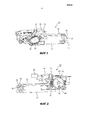
Фиг.1 - вид устройства в перспективе.Figure 1 is a perspective view of the device.
Фиг.2 - вид сбоку противоположной стороны устройства, представленного на фиг.1.Figure 2 is a side view of the opposite side of the device shown in figure 1.
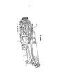
Фиг.3 - изображение устройства, представленного на фиг.1, в разобранном виде.Figure 3 - image of the device shown in figure 1, in disassembled form.
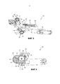
Фиг.4 - вид сбоку с частичным разрезом устройства, представленного на фиг.1.Figure 4 is a side view in partial section of the device shown in figure 1.
Фиг.5 - еще один вид в перспективе с изображением устройства.5 is another perspective view showing a device.
На фиг.1-5 представлено устройство, в целом обозначенное позицией 10, для создания последовательных выбросов воздуха и жидкости, такой как вода, которые смешиваются для создания потока из воздуха и капель жидкости, используемого для очистки зубов, особенно межзубных промежутков. Устройство 10 образует основную часть всего приспособления для очистки зубов, которое включает чехол, источник питания и элементы управления для управления устройством. Эти элементы являются стандартными в устройстве для очистки жидкостно-капельного типа и поэтому специально не показанными и не описанными в настоящем документе.Figures 1-5 show a device, generally indicated at 10, for generating successive emissions of air and liquid, such as water, which are mixed to create a stream of air and liquid droplets used to clean teeth, especially interdental spaces. The
Как показано на фиг.1 и 2, устройство 10 включает в себя воздушный цилиндр 12, который в показанном варианте осуществления имеет приблизительно 2,5 дюйма в длину и внутренний диаметр 0,5-1,0 дюйм. На дистальном конце 14 воздушного цилиндра 12 имеется патрубок, через который смесь выбросов воды или иной жидкости и текучей среды, обычно воздух, выходит. Капли жидкости направлены на зубы пользователя, особенно на межзубные промежутки, для их очистки.As shown in figures 1 and 2, the
Устройство включает в себя двигатель 20, который в представленном варианте осуществления представляет собой двигатель постоянного тока, как правило, с высоким крутящим моментом, например 15 ньютон-метров, хотя это значение обычно достигается после понижающей передачи. Таким образом, самому двигателю не требуется развивать такое значение крутящего момента. Такие двигатели широко представлены на рынке. Подходящими являются различные двигатели. Например, примерами подходящего двигателя являются двигатели компании Mitsumi. Двигатель 20 включает в себя выходной вал 21, на который установлен привод двигателя (фиг.4). В представленном варианте осуществления на ведущей шестерне двигателя имеется 8 зубцов. Количество зубцов шестерни 22, как и количество зубцов на других шестернях, может быть различным. Двигатель 20 расположен в позиции 24 на задней верхней поверхности воздушного цилиндра 12. Ведущая шестерня 22 двигателя зацепляет первую (наружную) зубчатую часть 26 первой составной шестерни 28, расположенной на первой стороне устройства. Первая составная шестерня 28 в данном варианте осуществления выполнен из пластика, как и остальные шестерни, однако она может быть выполнено также из других материалов. Первая зубчатая часть 26 первой составной шестерни 28 данного варианта осуществления 53 зубца. При работе ведущая шестерня 22 двигателя вращает ее по часовой стрелке. Первая составная шестерня 28 также включает в себя вал-шестерню 30 и вторую (внутреннюю) зубчатую часть 32, совпадающую с дистальным концом вала-шестерни 30, как показано на фиг.3. В представленном варианте осуществления вторая зубчатая часть первой составной шестерни имеет 8 зубцов.The device includes a
Вал 30 со второй зубчатой частью 32 первой составной шестерни 28 проходит через устройство 10 и сопрягается с первой (наружной) зубчатой частью 34 второй составной шестерни 36, расположенной на противоположной стороне устройства. В представленном варианте осуществления первый зубчатая часть 34 второй составной шестерни имеет 48 зубцов, хотя это значение может быть другим, как было отмечено выше. Вторая (внутренняя) зубчатая часть 38 второй составной шестерни 36 прилегает к центральному валу-шестерне 37. Вторая зубчатая часть второй составной шестерни имеет 2 части, первую часть, содержащую частичный набор из 8 зубцов, обозначенных позицией 39, расположенных на расстоянии друг от друга вокруг приблизительно половины периметра второй зубчатой части, и вторую часть, не содержащую зубцов, то есть поверхность является гладкой в основании зубчатого участка второй зубчатой части. Обычно, но не обязательно, эти две части занимают каждая половину второй зубчатой части.The
Второй составной центральный вал-шестерня 37 проходит обратно через устройство к первой стороне устройства и зацепляет узел 46 перистальтического насоса для текучей среды. Узел 46 перистальтического насоса включает в себя первый трубчатый участок 48, заходящий в резервуар 50 для текучей среды. В представленном варианте осуществления текучая среда в резервуаре 50 - это вода, хотя также могут использоваться другие текучие среды. Эти текучие среды включают в себя различные композиции, способствующие очистке зубов, такие как, например, хлоргексидин, ополаскивающие жидкости на основе перекиси водорода, водные смеси, питьевую соду, эфирные масла или жидкости для промывания ротовой полости. Узел 46 перистальтического насоса также включает в себя вторую трубку 52, проходящую от насоса и над корпусом устройства, к U-образному монтажному элементу 54 и затем вдоль наружной поверхности воздушного цилиндра к смесительной камере 58 на дистальном конце воздушного цилиндра.A second composite
Вторая зубчатая часть 38 второй составной шестерни 36 сопрягается с зубчатой рейкой 62, расположенной на проксимальном конце 61 воздушного цилиндра 12. В представленном варианте осуществления зубчатая рейка 62 имеет в длину приблизительно 2 дюйма и включает в себя набор из 8 расположенных на расстоянии друг от друга зубцов на ее верхней поверхности. Дистальный конец зубчатой рейки 62 включает в себя уплотняющий элемент 64, который сопрягается герметичным образом с внутренней поверхностью воздушного цилиндра 12. От дистального конца зубчатой рейки 62 в уплотнении 64 проходит и вокруг рейки вдоль большей части ее длины обвивается пружина 66 сжатия. Проксимальный конец 68 пружины 66 упирается в стопорный элемент 70 корпуса 20, как показано на фиг.4.The
В процессе работы при повороте ведущей шестерни 22 двигателя рейка 62 перемещается назад под действием частичного набора зубцов 39 второй зубчатой части второй составной шестерни в направлении от проксимального конца 61 воздушного цилиндра, прижимая пружину 66 к стопору 70. Воздух входит в воздушный цилиндр через отверстие на дистальном конце 14. В представленном варианте осуществления пружина 66 сжимается на 30 мм. В данном варианте осуществления пружина сжимается постепенно каждые 400-900 миллисекунд в зависимости от точной частоты вращения двигателя. Этот процесс может осуществляться быстрее чем каждые 400 миллисекунд, вплоть до 100 мс. Когда составная шестерня 36 поворачивается так, что не имеющий зубцов участок 40 второй зубчатой части составной шестерни 38 оказывается прилегающим к рейке, так что между второй составной шестерни и рейкой отсутствует зубчатое соединение и зубчатое зацепление перестает удерживать рейку, пружина 66 разжимается, быстро перемещая рейку вперед, перемещая герметичный конец рейки вперед в воздушный цилиндр, нагнетая выброс воздуха в смесительную камеру вместе с выбросом жидкости (воды), создаваемым насосом, приводимым в действие валом второй составной шестерни. Как правило, происходит один впрыск воздуха за оборот вала двигателя, каждые 400-900 миллисекунд (или быстрее), при этом приблизительно 0,15 мл текучей среды подается в смесительную камеру за один оборот вала двигателя.During operation, when the
Последовательные выбросы воздуха и жидкости поступают в смесительную камеру 58 с надлежащей, согласованной синхронностью, и полученная смесь выходит через патрубок 16 в направлении зубов пользователя для их очистки.Successive emissions of air and liquid enter the
Соответственно, было раскрыто устройство с одним двигателем, выполненное с возможностью обеспечивать необходимую мощность двигателя для генерирования как выборов жидкости, так и выбросов воздуха для создания потока капель жидкости.Accordingly, a device with a single engine was disclosed, configured to provide the necessary engine power to generate both fluid choices and air emissions to create a stream of liquid droplets.
Хотя в иллюстративных целях был описан предпочтительный вариант осуществления изобретения, следует понимать, что в этот вариант осуществления могут быть внесены различные изменения, модификации и замены без отступления от сущности изобретения, определяемого нижеследующей формулой.Although a preferred embodiment of the invention has been described for illustrative purposes, it should be understood that various changes, modifications, and replacements may be made to this embodiment without departing from the spirit of the invention as defined by the following claims.
Claims (9)
единственный двигатель (20);
первую составную шестерню (28), имеющую первый зубчатый участок (26) и второй зубчатый участок (32);
вторую составную шестерню (36), имеющую первый зубчатый участок (34) и второй зубчатый участок (38), при этом единственный двигатель приводит в действие первую составную шестерню, а первая составная шестерня приводит в действие вторую составную шестерню;
воздушный цилиндр (12);
смесительную камеру (58) на дистальном конце цилиндра, причем смесительная камера имеет выходной патрубок (16) для смеси жидкости и воздуха;
зубчатую рейку (62), имеющую дистальный герметизирующий конец (64), который сопрягается с внутренней поверхностью воздушного цилиндра непроницаемым для текучей среды образом, при этом второй участок второй составной шестерни сопрягается с зубчатой рейкой и приводит ее в движение, причем упомянутый один участок второй составной шестерни имеет зубцы только на своей части (39), а остальной участок не имеет зубцов;
пружинный элемент (66), установленный так, чтобы пружина сжималась при перемещении зубчатой рейки под действием второго участка второй составной шестерни; и
жидкостный насос (46), соединенный со второй составной шестерней так, что при повороте второй составной шестерни в смесительную камеру направляются последовательные выбросы жидкости, при этом, когда отсутствует зацепляющий контакт между указанным одним участком второй составной шестерни и зубчатой рейкой, пружина перемещает зубчатую рейку внутри воздушного цилиндра с такой скоростью, чтобы создавать выбросы воздуха в смесительную камеру, так что через патрубок с высокой скоростью выходит поток капель полученной смеси для очистки зубов.1. A device for use in a liquid droplet system for cleaning teeth to create sequential emissions of air and sequential emissions of liquid using one engine, containing:
single engine (20);
a first composite gear (28) having a first gear portion (26) and a second gear portion (32);
a second composite gear (36) having a first gear portion (34) and a second gear portion (38), wherein a single engine drives the first composite gear, and the first composite gear drives the second composite gear;
air cylinder (12);
a mixing chamber (58) at the distal end of the cylinder, the mixing chamber having an outlet pipe (16) for a mixture of liquid and air;
a gear rack (62) having a distal sealing end (64) that mates with the inner surface of the air cylinder in a fluid-tight manner, wherein the second portion of the second composite gear is mated to the gear and drives it, wherein said one portion of the second composite the gear has teeth only on its part (39), and the rest of the section has no teeth;
a spring element (66), mounted so that the spring is compressed when moving the rack under the action of the second section of the second compound gear; and
a fluid pump (46) connected to the second component gear so that when the second component gear is rotated, successive discharges of fluid are directed into the mixing chamber, while when there is no engaging contact between the indicated one section of the second component gear and the gear rack, the spring moves the gear rack inside an air cylinder at such a speed as to generate air emissions into the mixing chamber, so that a stream of droplets of the resulting mixture for cleaning teeth comes out through the nozzle at high speed .
Applications Claiming Priority (5)
| Application Number | Priority Date | Filing Date | Title |
|---|---|---|---|
| US38752710P | 2010-09-29 | 2010-09-29 | |
| US61/387,527 | 2010-09-29 | ||
| US201161447382P | 2011-02-28 | 2011-02-28 | |
| US61/447,382 | 2011-02-28 | ||
| PCT/IB2011/054167 WO2012042445A1 (en) | 2010-09-29 | 2011-09-22 | System for producing combined bursts of air and water for cleaning teeth |
Publications (2)
| Publication Number | Publication Date |
|---|---|
| RU2013119678A RU2013119678A (en) | 2014-11-10 |
| RU2577162C2 true RU2577162C2 (en) | 2016-03-10 |
Family
ID=44906258
Family Applications (1)
| Application Number | Title | Priority Date | Filing Date |
|---|---|---|---|
| RU2013119678/14A RU2577162C2 (en) | 2010-09-29 | 2011-09-22 | System for implementation of combined emission of air and water for cleaning teeth |
Country Status (9)
| Country | Link |
|---|---|
| US (1) | US8961174B2 (en) |
| EP (2) | EP2621399B1 (en) |
| JP (1) | JP5820481B2 (en) |
| CN (1) | CN103140188B (en) |
| BR (1) | BR112013007026A2 (en) |
| ES (1) | ES2626952T3 (en) |
| PL (1) | PL2749247T3 (en) |
| RU (1) | RU2577162C2 (en) |
| WO (1) | WO2012042445A1 (en) |
Families Citing this family (14)
| Publication number | Priority date | Publication date | Assignee | Title |
|---|---|---|---|---|
| EP2863833B1 (en) | 2012-06-22 | 2017-09-13 | Koninklijke Philips N.V. | Spring-driven pump for dispensing discrete bursts of liquid |
| CA2893095A1 (en) * | 2012-12-03 | 2014-06-12 | Koninklijke Philips N.V. | Discrete fluid burst oral cleaning appliance |
| JP6656928B2 (en) | 2013-03-15 | 2020-03-04 | コーニンクレッカ フィリップス エヌ ヴェKoninklijke Philips N.V. | Oral care device using jet-type fluid flow and mechanical action |
| WO2014141031A1 (en) * | 2013-03-15 | 2014-09-18 | Koninklijke Philips N.V. | An oral care appliance using pulsed fluid flow and mechanical action |
| EP2967773B1 (en) | 2013-03-15 | 2018-06-27 | Koninklijke Philips N.V. | Oral care appliance using a variable fluid flow |
| BR112015022376A2 (en) * | 2013-03-15 | 2017-07-18 | Koninklijke Philips Nv | mouth care appliance |
| BR112015022389A2 (en) * | 2013-03-15 | 2017-07-18 | Koninklijke Philips Nv | mouth care appliance |
| WO2014167454A1 (en) * | 2013-04-09 | 2014-10-16 | Koninklijke Philips N.V. | Oral cleaning appliance producing pulses of gas with mouthwash |
| US10849726B2 (en) | 2013-11-21 | 2020-12-01 | Koninklijke Philips N.V. | Air-driven interproximal toothbrush |
| EP3132984B1 (en) * | 2014-04-14 | 2019-11-20 | Koito Manufacturing Co., Ltd. | In vehicle device with foreign material removal |
| US10172688B2 (en) | 2015-06-24 | 2019-01-08 | Carlos Andres Castro-Perdomo | Steam cleaning device and methods of use |
| GB2554401B (en) * | 2016-09-26 | 2019-01-23 | Dyson Technology Ltd | Cleaning appliance |
| GB2554402B (en) * | 2016-09-26 | 2018-10-24 | Dyson Technology Ltd | Cleaning appliance |
| US11045294B2 (en) | 2017-06-01 | 2021-06-29 | Johnson & Johnson Consumer Inc. | Oral care cleaning system utilizing entrained fluid |
Citations (1)
| Publication number | Priority date | Publication date | Assignee | Title |
|---|---|---|---|---|
| SU1024079A1 (en) * | 1981-02-05 | 1983-06-23 | Донецкий государственный медицинский институт им.А.М.Горького | Stomatological device for hydrotherapeutic procedures |
Family Cites Families (6)
| Publication number | Priority date | Publication date | Assignee | Title |
|---|---|---|---|---|
| US6884069B2 (en) | 2001-07-12 | 2005-04-26 | The Gillette Company | Oral care device |
| AUPR873301A0 (en) | 2001-11-09 | 2001-11-29 | Venter, Heinrich | Tooth cleaning device |
| US6837708B2 (en) | 2002-04-29 | 2005-01-04 | Chien-Liang Chen | Device for generating a jet stream of air entrained water |
| CN201171723Y (en) * | 2007-11-16 | 2008-12-31 | 曹孝龙 | Multifunctional mouth flusher |
| CA2743798C (en) * | 2008-11-17 | 2017-05-02 | Koninklijke Philips Electronics N.V. | Appliance for delivering liquid to a gas stream for creating droplets in a dental cleaner |
| US20100167236A1 (en) * | 2008-12-29 | 2010-07-01 | Koninklijke Philips Electronics N.V. | Non-pressurized system fore creating liquid droplets in a dental cleaning appliance |
-
2011
- 2011-09-22 EP EP11778971.9A patent/EP2621399B1/en active Active
- 2011-09-22 US US13/819,813 patent/US8961174B2/en active Active
- 2011-09-22 WO PCT/IB2011/054167 patent/WO2012042445A1/en active Application Filing
- 2011-09-22 RU RU2013119678/14A patent/RU2577162C2/en active
- 2011-09-22 EP EP14161866.0A patent/EP2749247B1/en active Active
- 2011-09-22 ES ES14161866.0T patent/ES2626952T3/en active Active
- 2011-09-22 BR BR112013007026-9A patent/BR112013007026A2/en not_active IP Right Cessation
- 2011-09-22 PL PL14161866T patent/PL2749247T3/en unknown
- 2011-09-22 CN CN201180047161.0A patent/CN103140188B/en active Active
- 2011-09-22 JP JP2013530834A patent/JP5820481B2/en active Active
Patent Citations (1)
| Publication number | Priority date | Publication date | Assignee | Title |
|---|---|---|---|---|
| SU1024079A1 (en) * | 1981-02-05 | 1983-06-23 | Донецкий государственный медицинский институт им.А.М.Горького | Stomatological device for hydrotherapeutic procedures |
Also Published As
| Publication number | Publication date |
|---|---|
| ES2626952T3 (en) | 2017-07-26 |
| RU2013119678A (en) | 2014-11-10 |
| BR112013007026A2 (en) | 2020-10-13 |
| EP2749247A2 (en) | 2014-07-02 |
| EP2621399A1 (en) | 2013-08-07 |
| WO2012042445A1 (en) | 2012-04-05 |
| CN103140188B (en) | 2015-09-16 |
| EP2749247B1 (en) | 2017-03-01 |
| JP2013540518A (en) | 2013-11-07 |
| JP5820481B2 (en) | 2015-11-24 |
| US8961174B2 (en) | 2015-02-24 |
| PL2749247T3 (en) | 2017-08-31 |
| EP2621399B1 (en) | 2014-08-13 |
| CN103140188A (en) | 2013-06-05 |
| US20130177869A1 (en) | 2013-07-11 |
| EP2749247A3 (en) | 2015-05-20 |
Similar Documents
| Publication | Publication Date | Title |
|---|---|---|
| RU2577162C2 (en) | System for implementation of combined emission of air and water for cleaning teeth | |
| US9931186B2 (en) | Oral care appliance using a jet-type fluid flow and mechanical action | |
| US10860770B2 (en) | Oral care appliance using pulsed fluid flow | |
| US10034731B2 (en) | Oral care appliance using pulsed fluid flow and mechanical action | |
| CN105073062B (en) | Oral care appliance using a variable fluid flow | |
| JP2015527101A (en) | Spring driven pump for dispensing discrete jets of liquid | |
| JP2013540518A5 (en) | ||
| US20140154640A1 (en) | Dental hygiene device | |
| EP2967774B1 (en) | An oral care appliance using a jet-type fluid flow | |
| CN209203586U (en) | Tooth flusher | |
| CN109303618A (en) | Tooth flusher | |
| WO2014167454A1 (en) | Oral cleaning appliance producing pulses of gas with mouthwash | |
| CN116919641A (en) | Liquid outlet system of tooth washing device |