JP5820481B2 - System for generating combined bursts of air - Google Patents
System for generating combined bursts of air Download PDFInfo
- Publication number
- JP5820481B2 JP5820481B2 JP2013530834A JP2013530834A JP5820481B2 JP 5820481 B2 JP5820481 B2 JP 5820481B2 JP 2013530834 A JP2013530834 A JP 2013530834A JP 2013530834 A JP2013530834 A JP 2013530834A JP 5820481 B2 JP5820481 B2 JP 5820481B2
- Authority
- JP
- Japan
- Prior art keywords
- gear
- rack
- air
- compound
- spring
- Prior art date
- Legal status (The legal status is an assumption and is not a legal conclusion. Google has not performed a legal analysis and makes no representation as to the accuracy of the status listed.)
- Active
Links
Images


Classifications
-
- A—HUMAN NECESSITIES
- A61—MEDICAL OR VETERINARY SCIENCE; HYGIENE
- A61C—DENTISTRY; APPARATUS OR METHODS FOR ORAL OR DENTAL HYGIENE
- A61C17/00—Devices for cleaning, polishing, rinsing or drying teeth, teeth cavities or prostheses; Saliva removers; Dental appliances for receiving spittle
- A61C17/16—Power-driven cleaning or polishing devices
-
- A—HUMAN NECESSITIES
- A61—MEDICAL OR VETERINARY SCIENCE; HYGIENE
- A61C—DENTISTRY; APPARATUS OR METHODS FOR ORAL OR DENTAL HYGIENE
- A61C17/00—Devices for cleaning, polishing, rinsing or drying teeth, teeth cavities or prostheses; Saliva removers; Dental appliances for receiving spittle
- A61C17/02—Rinsing or air-blowing devices, e.g. using fluid jets or comprising liquid medication
- A61C17/028—Rinsing or air-blowing devices, e.g. using fluid jets or comprising liquid medication with intermittent liquid flow
-
- A—HUMAN NECESSITIES
- A61—MEDICAL OR VETERINARY SCIENCE; HYGIENE
- A61C—DENTISTRY; APPARATUS OR METHODS FOR ORAL OR DENTAL HYGIENE
- A61C1/00—Dental machines for boring or cutting ; General features of dental machines or apparatus, e.g. hand-piece design
- A61C1/0061—Air and water supply systems; Valves specially adapted therefor
- A61C1/0084—Supply units, e.g. reservoir arrangements, specially adapted pumps
- A61C1/0092—Pumps specially adapted therefor
Description
本発明は、概して、所望のエア/流体混合物を生成するためにエアのバースト及び流体のバーストの組み合わせを用いて歯をクリーニングするための装置に関し、より詳しくは、エアバースト及び流体バーストの双方を協働して生成するための単一のアセンブリに関する。 The present invention generally relates to an apparatus for cleaning teeth using a combination of air bursts and fluid bursts to produce a desired air / fluid mixture, and more particularly to both air bursts and fluid bursts. It relates to a single assembly for collaborative production.
エア及び水のような流体のバーストの組み合わせを有する歯垢取りをもたらすシステムにおいて、クリーニングの最も大きな有効性を達成するような態様でエア及び流体が混合されることが重要である。加えて、これらの2つの機能のタイミングを調整する一方で、構造及び動作について依然として比較的単純であり、特定のデバイスのフットプリントの範囲内で適合するように十分に小さいことが重要である。 In systems that provide plaque removal with a combination of bursts of fluid such as air and water, it is important that the air and fluid are mixed in a manner that achieves the greatest effectiveness of cleaning. In addition, it is important to coordinate the timing of these two functions while still being relatively simple in structure and operation and small enough to fit within the footprint of a particular device.
別々の液体及びエアデリバリーシステムの使用は、典型的には、タイミング、並びに、空間的制約及び二重電源の必要性に関する幾つかの課題を有する。液体及びエア生成機能の双方を達成し、その調整タイミングを与えるために単一の電源が用いられ得る機器を有することが有利であるだろう。 The use of separate liquid and air delivery systems typically has several challenges regarding timing and spatial constraints and the need for dual power supplies. It would be advantageous to have equipment in which a single power source can be used to achieve both liquid and air generation functions and provide timing for their adjustment.
1つの力アセンブリによりエアの連続したバースト及び液体の連続したバーストの双方を生成するための歯をクリーニングするための液滴システムで使用するための装置であって、単一のモータと、前記単一のモータにより駆動される第1のギアセンブリと、第2のギアセンブリであって、前記第1のギアセンブリの一部が前記第2のギアセンブリを駆動させる、第2のギアセンブリと、モータが動作したときに液体の連続したバーストを生成するように前記第2のギアセンブリにより駆動される液体ポンプと、エアのバーストを生成するためのスプリング駆動型アセンブリとを有し、前記第2のギアセンブリは、前記モータの各回転が、歯をクリーニングするための高速液滴のストリームを形成するために一緒に混合される、エアのバースト及び液体のバーストを生成するように、前記のスプリングアセンブリを駆動させる部分を含む、装置。 An apparatus for use in a droplet system for cleaning teeth to produce both a continuous burst of air and a continuous burst of liquid with a single force assembly, comprising: a single motor; A first gear assembly driven by a motor and a second gear assembly, a portion of the first gear assembly driving the second gear assembly; A liquid pump driven by the second gear assembly to generate a continuous burst of liquid when the motor is operated, and a spring driven assembly for generating a burst of air, the second The gear assembly is an air berth where each rotation of the motor is mixed together to form a stream of high speed droplets for cleaning the teeth. And to produce a burst of liquid, comprising a portion for driving the spring assembly, device.
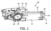
図1−4は、歯(特に歯の歯間エリア)をクリーニングするために使用されるエア及び液滴のストリームを生成するために混合されるエア及び水のような液体の連続したバーストを生成するための装置を概ね10で示している。装置10は、完全な歯垢取り機器の大部分を形成し、これは、装置を動作させるための制御要素、電源及びカバーを含む。これらの要素は、液滴タイプのクリーニング装置において通常のものであり、それ故、ここでは詳細に示されないし、詳細に説明されない。
1-4 generate a continuous burst of liquid such as air and water mixed to produce a stream of air and droplets used to clean the teeth (especially the interdental area of the teeth) An apparatus for doing so is indicated generally at 10. The
図1及び2を詳細に参照すると、装置10は、エアシリンダ12を含み、これは、示された実施形態においては、0.5−1.0インチの内径を有する約2.5インチの長さである。エアシリンダ12の遠位端14にはノズル16があり、このノズル16を介して、水又は他の液体バースト及び流体(典型的にはエア)の混合が高速液滴のストリームの形式で出る。液滴は、クリーニングのために、ユーザの歯(特に歯間エリア)に向かって指向される。
Referring to FIGS. 1 and 2 in detail, the
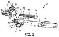
装置は、モータ20を含み、示された実施形態においては、典型的には高いトルク(例えば15Nm;この値は典型的にはギア減速後に実現される)を有するDCモータである。モータ自体は、それ故、トルクの斯様な値を自己で生成する必要はない。斯様なモータは、広く商業的に入手可能である。種々のモータが適切である。ミツミにより作られるモータは、例えば適切なモータの例である。モータ20は、モータ駆動ギア22(図4)が取り付けられた出力シャフト21を含む。示された実施形態では、モータ駆動ギア上に8つの歯がある。ギア22上の歯の数は、他のギア上の歯の数と同様に変えられ得る。モータ20は、エアシリンダ12の後部上側表面の24に配置される。モータ駆動ギア22は、装置の第1の側に配置される第1の複合ギア28の第1の(外側の)ギア部分26と係合する。示された実施例における第1の複合ギア28は、他のギアと同様にプラスチックで作られるが、他の材料で作られてもよい。示された実施形態におけるギア28の第1のギア部分26は、53の歯を有する。動作中のモータ駆動ギア22は、時計回り方向に回転する。図3に示すように、第1の複合ギア28は、ギアシャフト30と、シャフト30の遠位端と一致する第2の(内側)ギア部分32とを含む。示された実施形態においては、第1の複合ギアの第2のギア部分は、8つの歯を有する。
The apparatus includes a
第1の複合ギア28の第2ギア部分32を有するシャフト30は、装置10を介して延在し、装置の対向面上に配置される第2の複合ギア36の第1の(外側)ギア部分34と嵌合する。示された実施形態においては、第2の複合ギアの第1のギア部分34は、48の歯を有するが、前に述べたように、これは変えられ得る。第2の複合ギア36の第2の(内側)ギア部分38は、中心ギアシャフト37上に第1のギア部分34に隣接して配置される。第2の複合ギアの第2ギア部分は、2つの部分、即ち、第2ギア部分の円周の約1/2を間隔を空けて囲んでいる、39で参照される8つの歯の部分的なセットを有する第1の部分と、歯をもたない、即ち、表面が第2ギア部分の歯部分の基部で滑らかである、第2の部分40とを有する。典型的には、必然的ではないが、2つの部分は第2のギア部分の各1/2である。
A
第2の複合中央ギアシャフト37は、装置の第1の側まで戻るように装置を介して延在し、ポンプ48を含む蠕動運動流体ポンプアセンブリ46と係合する。蠕動運動ポンプアセンブリ46は、流体タンク50まで延在する第1の管部材48を含む。示された実施形態においては、タンク50内の流体は水であるが、他の流体が同様に用いられてもよい。これらは、例えば、クロルヘキシジン、過酸化水素系洗浄剤、水の混合物、重曹、精油又はうがい薬のような、歯のクリーニングを支援する種々の製剤を含む。また、蠕動運動ポンプアセンブリ46は、U型の取付要素54における、ポンプ及び装置の本体の上から、エアシリンダの外面に沿って、エアシリンダの遠位端上の混合チャンバ58まで延在する第2の管52を含む。
A second composite
第2の複合ギア36の第2ギア部分38は、エアシリンダ12の近位端61に配置される線状ラック部材62と嵌合する。示された実施形態においては、ラック部材62は、約2インチの長さであり、その上側表面上に8つの間隔が空けられた歯のセットを含む。ラック部材62の遠位端は、エアシリンダ12の内面との液密関係において嵌合する封止部材64を含む。圧縮スプリング66は、封止部64におけるラック62の遠位端から延在しており、その上の長さの大部分に沿ってラックを囲んでいる。図4に示すように、スプリング66の近位端68は、本体部分20における停止要素70に対して配置される。
The
動作中、モータ駆動ギア22が回転したときには、ラック62は、第2の複合ギアの第2のギア部分の歯39の部分的なセットの動作により、エアシリンダの近位端61から離れて、停止部70に対してばね66を圧縮するように、後方に移動する。エアは、遠位端14の開口部を介してエアシリンダに入る。示された実施形態においては、スプリング66は、30mmの圧縮を受ける。本実施形態においては、スプリングは、モータの正確なrpmに応じて400−900ミリ秒毎に連続的に圧縮される。400ms毎よりも速く動作することが可能であり、100msまで下がる場合であっても可能である。位置的にラックを保持しているギア接触を伴うことなく、第2の複合ギアとラックとの間にギア接続がないように、複合ギア38の第2ギア部分の歯のないギア部分40がラックに隣接するように第2の複合ギア36が回転したときには、スプリング66は、前方へ急速にラックを移動させるように動作し、エアシリンダにおけるラックの封止された端部を前方へ移動させ、第2の複合ギアのシャフトにより駆動された、ポンプの動作により生成された、液体(水)のバーストと一緒に、エアのバーストを混合チャンバに押し込む。典型的には、モータシャフトの回転ごと、即ち400−900ミリ秒(又は、より速い)ごとにエアのワンショットがある。モータシャフトの回転ごとに混合チャンバに与えられる約0.15mmの流体がある。
In operation, when the
エア及び液体の連続したバーストは、適切な一貫したタイミングで混合チャンバ58に一緒に送り込まれ、この混合チャンバ58から、結果として生じる混合が、歯のクリーニングのためにユーザの歯に向かって指向されたノズル16を介して出る。
Successive bursts of air and liquid are pumped together into the
従って、液滴のストリームを生成するためにエアのバースト及び流体バーストの両方の生成のための必要な運動力を与えるように構成された単一のモータ装置が開示された。 Accordingly, a single motor device has been disclosed that is configured to provide the requisite kinetic force for the generation of both air and fluid bursts to generate a stream of droplets.
好ましい実施形態が説明のために開示されたが、種々の改変と変更態様及び置換が、特許請求の範囲によって規定された本発明の精神を逸脱することなく好ましい実施形態において行われ得ることが理解されるべきである。 While preferred embodiments have been disclosed for purposes of illustration, it will be understood that various modifications, changes and substitutions may be made in the preferred embodiments without departing from the spirit of the invention as defined by the claims. It should be.
Claims (12)
単一のモータと、
第1のギア部分及び第2のギア部分を有する第1の複合ギアと、
第1のギア部分及び第2のギア部分を有する第2の複合ギアであって、前記単一のモータが前記第1の複合ギアを駆動させ、前記第1の複合ギアが前記第2の複合ギアを駆動させる、第2の複合ギアと、
エアシリンダと、
液体及びエアの混合のための出口ノズルを有する、前記エアシリンダの遠位端にある混合チャンバと、
流体密関係において前記エアシリンダの内面と嵌合する遠位封止端を有するラック部材であって、前記第2の複合ギアの第2の部分が、前記のラックと嵌合するとともに前記のラックを駆動させ、前記の第2の複合部材の一部が、その部分に渡ってのみ歯を有し、残部が歯を有さない、ラック部材と、
前記ラックが前記第2の複合ギアの前記第2の部分の動作により動かされたときにスプリングが圧縮するように取り付けられたスプリング部材と、
前記第2の複合ギアが回転したときに液体の連続したバーストが前記混合チャンバに指向されるように前記第2の複合ギアに接続された液体ポンプであって、前記第2の複合ギアの前記一部と前記ラックとの間に係合接触がないときには、前記スプリングは、液滴の結果として生じる混合物ストリームは、歯のクリーニングのための前記ノズルを介して高速度で出るように、前記エアシリンダ内の前記ラックを、エアのバーストを生成するような速度で前記混合チャンバまで移動させる、液体ポンプとを有する、装置。 An apparatus for use in a droplet system for tooth cleaning to produce a continuous burst of air and a continuous burst of liquid with a single motor assembly comprising:
With a single motor,
A first compound gear having a first gear portion and a second gear portion;
A second compound gear having a first gear portion and a second gear portion, wherein the single motor drives the first compound gear, and the first compound gear is the second compound gear. A second compound gear for driving the gear;
An air cylinder;
A mixing chamber at the distal end of the air cylinder having an outlet nozzle for mixing liquid and air;
A rack member having a distal sealing end mating with the inner surface of the air cylinder in a fluid tight relationship, wherein the second portion of the second compound gear is mated with the rack and the rack. A rack member in which a portion of the second composite member has teeth only over that portion and the remainder does not have teeth;
A spring member attached so that a spring is compressed when the rack is moved by movement of the second portion of the second compound gear;
A liquid pump connected to the second compound gear such that a continuous burst of liquid is directed to the mixing chamber when the second compound gear rotates, wherein the second compound gear of the second compound gear; When there is no engaging contact between the part and the rack, the spring will allow the mixture stream resulting from the droplets to flow at a high speed through the nozzle for tooth cleaning. A liquid pump that moves the rack in a cylinder to the mixing chamber at such a speed as to generate a burst of air.
前記モータは、前記第1の複合ギアの前記第2のギア部分とおおよそ同じ歯の数を有する駆動ギアを有する、請求項2に記載の装置。 The first gear portion of the first compound gear has at least five times the teeth of the second gear portion;
The apparatus of claim 2, wherein the motor has a drive gear having approximately the same number of teeth as the second gear portion of the first compound gear.
前記第2のギア部分は、前記第2のギア部分の一部に渡ってのみ歯を有し、
前記第2の複合ギアの、歯を伴わない、前記第2のギア部分の残部が前記ラックに隣接したときに、前記ラックは、解放され、スプリング動作により前記エアシリンダを介してすばやく移動する、請求項1に記載の装置。 The first gear portion of the second compound gear has substantially more teeth than the second gear portion;
The second gear portion has teeth only over a portion of the second gear portion;
The rack is released when the remainder of the second gear portion of the second compound gear, without teeth, is adjacent to the rack, and moves quickly through the air cylinder by a spring action; The apparatus of claim 1.
前記第1の複合ギア部分の前記第2のギア部分は、前記第2の複合ギアの前記第1のギア部分を駆動させる、請求項3に記載の装置。 The first gear portions of the first and second compound gears are disposed on opposite sides of the device;
4. The apparatus of claim 3, wherein the second gear portion of the first compound gear portion drives the first gear portion of the second compound gear.
前記ポンプは、前記モータの回転毎におおよそ0.15mlの液体バーストを生成し、
エアバーストは、前記混合チャンバにおいて混合効果を生成するように調節された、400−900ミリ秒毎に生成される、請求項1に記載の装置。 The spring compresses approximately 30 mm during operation,
The pump produces approximately 0.15 ml of liquid burst per rotation of the motor,
The apparatus of claim 1, wherein an air burst is generated every 400-900 milliseconds adjusted to produce a mixing effect in the mixing chamber.
前記スプリング部材の遠位端は、前記ラック部材の前記封止端に接続され、
前記ラック部材が解放されたときに、前記スプリング動作は、その遠位端に向かって前記エアシリンダの長さに沿って前記ラック部材の前記封止端を押し込む、請求項1に記載の装置。 An apparatus main body including a stop member to which the spring member is compressed,
A distal end of the spring member is connected to the sealed end of the rack member;
The apparatus of claim 1, wherein when the rack member is released, the spring action pushes the sealed end of the rack member along the length of the air cylinder toward its distal end.
単一のモータと、
前記単一のモータにより駆動される第1のギアセンブリと、
第2のギアセンブリであって、前記第1のギアセンブリの一部が前記第2のギアセンブリを駆動させる、第2のギアセンブリと、
モータが動作したときに液体の連続したバーストを生成するように前記第2のギアセンブリにより駆動される液体ポンプと、
エアのバーストを生成するためのスプリング駆動型アセンブリとを有し、
前記第2のギアセンブリは、前記モータの各回転が、歯をクリーニングするための高速液滴のストリームを形成するために一緒に混合される、協働したエアのバースト及び液体のバーストを生成するように、前記のスプリング駆動型アセンブリにおけるスプリング部材を圧縮及び解放して前記単一のモータの回転ごとに前記スプリング駆動型アセンブリからエアのバーストを生成するように構成された部分を含む、装置。 An apparatus for use in a droplet system for cleaning teeth to produce both a continuous burst of air and a continuous burst of liquid with a single force assembly comprising:
With a single motor,
A first gear assembly driven by the single motor;
A second gear assembly, wherein a portion of the first gear assembly drives the second gear assembly;
A liquid pump driven by the second gear assembly to produce a continuous burst of liquid when the motor is operated;
A spring driven assembly for generating a burst of air;
The second gear assembly produces a collaborative burst of air and liquid that each rotation of the motor is mixed together to form a stream of high speed droplets for cleaning teeth. as described above, comprising a portion configured to generate an air burst from the spring-driven assembly for each rotation of said spring member in a spring-driven assembly compression and release to the single motor, device.
前記線状ラックは、その一端で封止部材を含み、前記シール部材は、流体密関係において前記エアシリンダの内面と嵌合する、請求項11に記載の装置。 The spring-driven assembly includes a linear rack and an air cylinder that are engaged and driven by a portion of the second gear assembly, and the spring member is moved by the movement of a portion of the second gear assembly. When the linear rack is moved, the spring member is mounted to be compressed and released,
The apparatus of claim 11, wherein the linear rack includes a sealing member at one end thereof, and the sealing member engages an inner surface of the air cylinder in a fluid tight relationship.
Applications Claiming Priority (5)
| Application Number | Priority Date | Filing Date | Title |
|---|---|---|---|
| US38752710P | 2010-09-29 | 2010-09-29 | |
| US61/387,527 | 2010-09-29 | ||
| US201161447382P | 2011-02-28 | 2011-02-28 | |
| US61/447,382 | 2011-02-28 | ||
| PCT/IB2011/054167 WO2012042445A1 (en) | 2010-09-29 | 2011-09-22 | System for producing combined bursts of air and water for cleaning teeth |
Publications (3)
| Publication Number | Publication Date |
|---|---|
| JP2013540518A JP2013540518A (en) | 2013-11-07 |
| JP2013540518A5 JP2013540518A5 (en) | 2014-10-30 |
| JP5820481B2 true JP5820481B2 (en) | 2015-11-24 |
Family
ID=44906258
Family Applications (1)
| Application Number | Title | Priority Date | Filing Date |
|---|---|---|---|
| JP2013530834A Active JP5820481B2 (en) | 2010-09-29 | 2011-09-22 | System for generating combined bursts of air |
Country Status (9)
| Country | Link |
|---|---|
| US (1) | US8961174B2 (en) |
| EP (2) | EP2621399B1 (en) |
| JP (1) | JP5820481B2 (en) |
| CN (1) | CN103140188B (en) |
| BR (1) | BR112013007026A2 (en) |
| ES (1) | ES2626952T3 (en) |
| PL (1) | PL2749247T3 (en) |
| RU (1) | RU2577162C2 (en) |
| WO (1) | WO2012042445A1 (en) |
Families Citing this family (14)
| Publication number | Priority date | Publication date | Assignee | Title |
|---|---|---|---|---|
| JP6430376B2 (en) * | 2012-06-22 | 2018-11-28 | コーニンクレッカ フィリップス エヌ ヴェKoninklijke Philips N.V. | Spring driven pump for dispensing discrete jets of liquid |
| CN104822341B (en) * | 2012-12-03 | 2017-11-17 | 皇家飞利浦有限公司 | Discrete fluid bursts out Oral cleaner |
| US9931186B2 (en) | 2013-03-15 | 2018-04-03 | Koninklijke Philips N.V. | Oral care appliance using a jet-type fluid flow and mechanical action |
| WO2014140997A1 (en) * | 2013-03-15 | 2014-09-18 | Koninklijke Philips N.V. | An oral care appliance using a jet-type fluid flow |
| CN105228554B (en) * | 2013-03-15 | 2017-08-11 | 皇家飞利浦有限公司 | Use the oral care implement of pulsed flow stream |
| RU2015144174A (en) * | 2013-03-15 | 2017-04-25 | Конинклейке Филипс Н.В. | ORAL CARE DEVICE USING PULSE FLUID FLOW AND MECHANICAL ACTION |
| WO2014140979A1 (en) * | 2013-03-15 | 2014-09-18 | Koninklijke Philips N.V. | Oral care appliance using a variable fluid flow |
| WO2014167454A1 (en) * | 2013-04-09 | 2014-10-16 | Koninklijke Philips N.V. | Oral cleaning appliance producing pulses of gas with mouthwash |
| RU2016124212A (en) | 2013-11-21 | 2017-12-26 | Конинклейке Филипс Н.В. | DENTAL BRUSH FOR INTER-DENTAL SPACES, DRIVING BY AIR |
| CN106163888B (en) * | 2014-04-14 | 2019-06-28 | 株式会社小糸制作所 | Foreign substance removing apparatus |
| US10172688B2 (en) * | 2015-06-24 | 2019-01-08 | Carlos Andres Castro-Perdomo | Steam cleaning device and methods of use |
| GB2554402B (en) | 2016-09-26 | 2018-10-24 | Dyson Technology Ltd | Cleaning appliance |
| GB2554401B (en) * | 2016-09-26 | 2019-01-23 | Dyson Technology Ltd | Cleaning appliance |
| US11045294B2 (en) | 2017-06-01 | 2021-06-29 | Johnson & Johnson Consumer Inc. | Oral care cleaning system utilizing entrained fluid |
Family Cites Families (7)
| Publication number | Priority date | Publication date | Assignee | Title |
|---|---|---|---|---|
| SU1024079A1 (en) * | 1981-02-05 | 1983-06-23 | Донецкий государственный медицинский институт им.А.М.Горького | Stomatological device for hydrotherapeutic procedures |
| US6884069B2 (en) | 2001-07-12 | 2005-04-26 | The Gillette Company | Oral care device |
| AUPR873301A0 (en) | 2001-11-09 | 2001-11-29 | Venter, Heinrich | Tooth cleaning device |
| US6837708B2 (en) | 2002-04-29 | 2005-01-04 | Chien-Liang Chen | Device for generating a jet stream of air entrained water |
| CN201171723Y (en) * | 2007-11-16 | 2008-12-31 | 曹孝龙 | Multifunctional mouth flusher |
| CA2743798C (en) * | 2008-11-17 | 2017-05-02 | Koninklijke Philips Electronics N.V. | Appliance for delivering liquid to a gas stream for creating droplets in a dental cleaner |
| US20100167236A1 (en) * | 2008-12-29 | 2010-07-01 | Koninklijke Philips Electronics N.V. | Non-pressurized system fore creating liquid droplets in a dental cleaning appliance |
-
2011
- 2011-09-22 EP EP11778971.9A patent/EP2621399B1/en active Active
- 2011-09-22 PL PL14161866T patent/PL2749247T3/en unknown
- 2011-09-22 US US13/819,813 patent/US8961174B2/en active Active
- 2011-09-22 BR BR112013007026-9A patent/BR112013007026A2/en not_active IP Right Cessation
- 2011-09-22 CN CN201180047161.0A patent/CN103140188B/en active Active
- 2011-09-22 ES ES14161866.0T patent/ES2626952T3/en active Active
- 2011-09-22 JP JP2013530834A patent/JP5820481B2/en active Active
- 2011-09-22 EP EP14161866.0A patent/EP2749247B1/en active Active
- 2011-09-22 RU RU2013119678/14A patent/RU2577162C2/en active
- 2011-09-22 WO PCT/IB2011/054167 patent/WO2012042445A1/en active Application Filing
Also Published As
| Publication number | Publication date |
|---|---|
| WO2012042445A1 (en) | 2012-04-05 |
| ES2626952T3 (en) | 2017-07-26 |
| RU2013119678A (en) | 2014-11-10 |
| RU2577162C2 (en) | 2016-03-10 |
| BR112013007026A2 (en) | 2020-10-13 |
| EP2749247A3 (en) | 2015-05-20 |
| EP2749247A2 (en) | 2014-07-02 |
| US8961174B2 (en) | 2015-02-24 |
| EP2749247B1 (en) | 2017-03-01 |
| JP2013540518A (en) | 2013-11-07 |
| EP2621399A1 (en) | 2013-08-07 |
| US20130177869A1 (en) | 2013-07-11 |
| CN103140188B (en) | 2015-09-16 |
| PL2749247T3 (en) | 2017-08-31 |
| EP2621399B1 (en) | 2014-08-13 |
| CN103140188A (en) | 2013-06-05 |
Similar Documents
| Publication | Publication Date | Title |
|---|---|---|
| JP5820481B2 (en) | System for generating combined bursts of air | |
| JP2013540518A5 (en) | ||
| US9931186B2 (en) | Oral care appliance using a jet-type fluid flow and mechanical action | |
| EP2967777B1 (en) | An oral care appliance using pulsed fluid flow | |
| EP2967778B1 (en) | An oral care appliance using pulsed fluid flow and mechanical action | |
| JP5972487B2 (en) | Oral care device using variable fluid flow | |
| JP6430376B2 (en) | Spring driven pump for dispensing discrete jets of liquid | |
| WO2008012707A2 (en) | Liquid interdental cleaner | |
| WO2014140964A1 (en) | An oral care appliance using a variable fluid flow and mechanical action. | |
| EP2967774B1 (en) | An oral care appliance using a jet-type fluid flow | |
| US4813602A (en) | Pulsating liquid cleaning device | |
| US10952813B2 (en) | Spring-driven pump for dispensing discrete bursts of liquid | |
| WO2014167454A1 (en) | Oral cleaning appliance producing pulses of gas with mouthwash |
Legal Events
| Date | Code | Title | Description |
|---|---|---|---|
| A521 | Request for written amendment filed |
Free format text: JAPANESE INTERMEDIATE CODE: A523 Effective date: 20140910 |
|
| A621 | Written request for application examination |
Free format text: JAPANESE INTERMEDIATE CODE: A621 Effective date: 20140910 |
|
| A977 | Report on retrieval |
Free format text: JAPANESE INTERMEDIATE CODE: A971007 Effective date: 20150821 |
|
| TRDD | Decision of grant or rejection written | ||
| A01 | Written decision to grant a patent or to grant a registration (utility model) |
Free format text: JAPANESE INTERMEDIATE CODE: A01 Effective date: 20150915 |
|
| A61 | First payment of annual fees (during grant procedure) |
Free format text: JAPANESE INTERMEDIATE CODE: A61 Effective date: 20151002 |
|
| R150 | Certificate of patent or registration of utility model |
Ref document number: 5820481 Country of ref document: JP Free format text: JAPANESE INTERMEDIATE CODE: R150 |
|
| R250 | Receipt of annual fees |
Free format text: JAPANESE INTERMEDIATE CODE: R250 |
|
| R250 | Receipt of annual fees |
Free format text: JAPANESE INTERMEDIATE CODE: R250 |
|
| R250 | Receipt of annual fees |
Free format text: JAPANESE INTERMEDIATE CODE: R250 |
|
| R250 | Receipt of annual fees |
Free format text: JAPANESE INTERMEDIATE CODE: R250 |
|
| R250 | Receipt of annual fees |
Free format text: JAPANESE INTERMEDIATE CODE: R250 |
|
| R250 | Receipt of annual fees |
Free format text: JAPANESE INTERMEDIATE CODE: R250 |