RU2575111C2 - Straightening device with hyperbolic rolls for metals and method implemented by said device - Google Patents
Straightening device with hyperbolic rolls for metals and method implemented by said device Download PDFInfo
- Publication number
- RU2575111C2 RU2575111C2 RU2014104023/02A RU2014104023A RU2575111C2 RU 2575111 C2 RU2575111 C2 RU 2575111C2 RU 2014104023/02 A RU2014104023/02 A RU 2014104023/02A RU 2014104023 A RU2014104023 A RU 2014104023A RU 2575111 C2 RU2575111 C2 RU 2575111C2
- Authority
- RU
- Russia
- Prior art keywords
- roller block
- hydraulic
- lower roller
- chamber
- specified
- Prior art date
Links
- 239000002184 metal Substances 0.000 title claims abstract description 22
- 229910052751 metal Inorganic materials 0.000 title claims abstract description 22
- 238000000034 method Methods 0.000 title claims description 7
- 150000002739 metals Chemical class 0.000 title 1
- 239000012530 fluid Substances 0.000 claims description 13
- 230000009471 action Effects 0.000 claims description 11
- 230000015572 biosynthetic process Effects 0.000 claims description 2
- 238000013461 design Methods 0.000 abstract description 2
- 238000001514 detection method Methods 0.000 abstract 1
- 238000010327 methods by industry Methods 0.000 abstract 1
- 239000000126 substance Substances 0.000 abstract 1
- 238000012423 maintenance Methods 0.000 description 6
- 230000008439 repair process Effects 0.000 description 5
- 230000008901 benefit Effects 0.000 description 4
- 238000009434 installation Methods 0.000 description 4
- 230000035484 reaction time Effects 0.000 description 4
- 230000006378 damage Effects 0.000 description 3
- 230000033228 biological regulation Effects 0.000 description 2
- 230000008859 change Effects 0.000 description 1
- 238000010276 construction Methods 0.000 description 1
- 230000007547 defect Effects 0.000 description 1
- 230000001419 dependent effect Effects 0.000 description 1
- 230000005484 gravity Effects 0.000 description 1
- 238000004519 manufacturing process Methods 0.000 description 1
- 239000000463 material Substances 0.000 description 1
- 238000012986 modification Methods 0.000 description 1
- 230000004048 modification Effects 0.000 description 1
- 230000008569 process Effects 0.000 description 1
- 238000012545 processing Methods 0.000 description 1
- 230000009467 reduction Effects 0.000 description 1
Images

Abstract
Description
Область техникиTechnical field
Настоящее изобретение относится к правильному устройству с гиперболическими роликами для металлических изделий и способу, выполняемому посредством такого устройства.The present invention relates to a correct device with hyperbolic rollers for metal products and a method performed by such a device.
Настоящее изобретение, в том числе, но не исключительно, применяют для правки длинномерных металлических изделий, таких как круглые заготовки, балки или трубы, выходящие с рабочей линии.The present invention, including, but not limited to, is used for dressing long metal products such as round billets, beams or pipes exiting from the working line.
В частности, предлагаемое правильное устройство используют для придания длинномерным металлическим изделиям, имеющим диаметр в диапазоне от 5 до 250 мм, требуемых окончательных допусков на размеры.In particular, the proposed correct device is used to give long-sized metal products having a diameter in the range from 5 to 250 mm the required final dimensional tolerances.
Уровень техникиState of the art
Известно, что в области обработки металлических изделий, в частности длинномерных или прутковых металлических изделий, для осуществления чистового прохода используют так называемую правильную машину, функция которой состоит в придании изделиям окончательных допусков на размеры.It is known that in the field of processing metal products, in particular long or bar metal products, the so-called straightening machine, the function of which is to give the products final dimensional tolerances, is used to complete the finish pass.
В указанной области широко распространено использование правильных машин, оснащенных гиперболическими роликами, в которых противоположные ролики установлены под углом друг к другу для сообщения металлическому изделию при прохождении между указанными роликами вращательно-поступательного движения, которое задает как продвижение вперед, так и вращение вокруг их оси.In this area, the use of straightening machines equipped with hyperbolic rollers is widespread, in which the opposite rollers are mounted at an angle to each other to communicate with the metal product when the rotational-translational movement passes between the indicated rollers, which determines both forward movement and rotation around their axis.
Размер прохода между двумя роликами обычно регулируют в зависимости от размера изделия, подлежащего обработке.The size of the passage between the two rollers is usually adjusted depending on the size of the product to be processed.
Как правило, известные правильные машины также имеют предохранительное/управляющее устройство, используемое для защиты целостности и функциональности машины в случае возникновения условий перегрузки из-за того, что изделия, поступающие в машину, имеют чрезмерно большие размеры по отношению к тем размерам, под которые она была настроена.As a rule, known straightening machines also have a safety / control device used to protect the integrity and functionality of the machine in case of overload conditions due to the fact that the products entering the machine are excessively large in relation to the dimensions under which it has been customized.
Условия перегрузки возникают тогда, когда давление, прилагаемое к ролику, превышает максимальное заданное давление. Это происходит, например, если изделия имеют слишком большие размеры, или, в частности, овальную форму и, тем самым, требуют наличия большего прохода, чем тот, что предусмотрен между двумя роликами.Overload conditions occur when the pressure applied to the roller exceeds the maximum set pressure. This happens, for example, if the products are too large, or, in particular, oval and, therefore, require a larger passage than the one provided between the two rollers.
Известные правильные машины можно разделить на две основные группы. К первой группе относятся машины, в которых оба ролика, верхний и нижний, подвижны, с возможностью перемещения в вертикальном направлении для начальной установки надлежащего размера прохода для обрабатываемого изделия. Ко второй группе относятся машины, в которых в вертикальном направлении перемещается только верхний ролик, а нижний ролик остается неподвижным.Known correct machines can be divided into two main groups. The first group includes machines in which both rollers, upper and lower, are movable, with the possibility of moving in the vertical direction for the initial installation of the proper size of the passage for the workpiece. The second group includes machines in which only the upper roller moves in the vertical direction, and the lower roller remains stationary.
В правильных машинах первой группы предохранительное/управляющее устройство расположено на обоих роликах так, что при включении оно обеспечивает движение обоих роликов. Пример такого типа правильной машины раскрыт в документе DE 19724300, в котором оба ролика имеют гидравлическую систему, предназначенную как для задания начального размера прохода, так и для управления условиями перегрузки.In the correct machines of the first group, the safety / control device is located on both rollers so that when turned on it ensures the movement of both rollers. An example of this type of straightening machine is disclosed in DE 19724300, in which both rollers have a hydraulic system designed both to set the initial passage size and to control overload conditions.
В правильных машинах второй группы предохранительное/управляющее устройство расположено только на верхнем ролике, поскольку указанный ролик является единственным подвижным роликом.In the correct machines of the second group, the safety / control device is located only on the upper roller, since this roller is the only movable roller.
В данном случае, верхним роликом не только управляют механическим или гидравлическим способом, но также оснащают указанный ролик гидравлической системой для поддержания силы, возникающей между роликом и изделием, ниже заданного значения, при превышении которого гидравлическая система обеспечивает поднятие ролика.In this case, the upper roller is not only controlled mechanically or hydraulically, but also the specified roller is equipped with a hydraulic system to maintain the force arising between the roller and the product below a predetermined value, above which the hydraulic system lifts the roller.
В известных правильных машинах движение одного или обоих роликов осуществляют за счет использования одного или более гидравлических цилиндров, которые могут быть двойного или одинарного действия, или представлять комбинацию обоих.In known straightening machines, the movement of one or both rollers is accomplished by using one or more hydraulic cylinders, which can be double or single acting, or represent a combination of both.
Недостаток известных правильных машин с гиперболическими роликами, относящихся к первой группе, заключается в том, что как подвижный блок, так и управляющее/предохранительное устройство, расположенные на обоих роликах, отличаются сложностью в изготовлении и управлении.A disadvantage of the known correct machines with hyperbolic rollers belonging to the first group is that both the movable unit and the control / safety device located on both rollers are difficult to manufacture and operate.
Еще один недостаток, присущий правильным машинам обеих групп, заключается в том, что движение верхнего ролика при включенном управляющем/предохранительном устройстве требует приложения значительных сил для его поднятия (вес одного такого ролика варьируется от нескольких сотен килограмм до нескольких тонн, в зависимости от размеров машины). Это определяет довольно длительное время реакции, намного превышающее время, необходимое, чтобы адекватно среагировать на ситуацию возможного повреждения машины.Another drawback inherent in the correct machines of both groups is that the movement of the upper roller with the control / safety device turned on requires significant forces to lift it (the weight of one such roller varies from several hundred kilograms to several tons, depending on the size of the machine ) This determines a rather long reaction time, far exceeding the time required to adequately respond to the situation of possible damage to the machine.
Другой недостаток состоит в том, что во время технического обслуживания и ремонта управляющего/предохранительного устройства и верхнего ролика, необходимо работать на расстоянии нескольких метров от земли, а также использовать средства перемещения, такие как подъемные или козловые краны, для получения доступа к отдельным частям машины. Это влечет за собой значительное увеличение затрат и времени работ.Another disadvantage is that during maintenance and repair of the control / safety device and the upper roller, it is necessary to work at a distance of several meters from the ground, as well as use moving means, such as cranes or gantry cranes, to gain access to individual parts of the machine . This entails a significant increase in costs and uptime.
В документе US-A-4763504 раскрыта правильная машина с гиперболическими роликами, в которой предусмотрено регулировочное и предохранительное устройство, обеспечивающее защиту от перегрузок и соединенное с нижним роликом. Указанное устройство содержит регулировочный болт, опорой для которого служит полый поршень, удерживаемый в нормальном положении посредством неподвижного крепежного элемента. Полый поршень служит опорой для регулировочного болта относительно поверхности, которая выходит вместе с поршнем, когда давление, прилагаемое к ролику, превышает заданное значение.US-A-4763504 discloses a correct machine with hyperbolic rollers, in which an adjusting and safety device is provided that provides overload protection and is connected to the lower roller. The specified device contains an adjusting bolt, the support for which is a hollow piston, held in a normal position by means of a fixed fastener. The hollow piston supports the adjusting bolt relative to the surface that exits with the piston when the pressure exerted on the roller exceeds a predetermined value.
Задача настоящего изобретения состоит в том, чтобы упростить общую конструкцию устройства, систему управления его функционированием, а также упростить выполнение всех работ по техническому обслуживанию, замене деталей и по обеспечению безопасности операторов, что позволит значительно сэкономить время и оборудование и, следовательно, приведет к существенным преимуществам с экономической точки зрения.The objective of the present invention is to simplify the overall design of the device, the control system for its functioning, as well as to simplify the performance of all maintenance, replacement parts and to ensure the safety of operators, which will significantly save time and equipment and, therefore, will lead to significant benefits from an economic point of view.
Другая задача настоящего изобретения заключается в том, чтобы получить правильную машины с гиперболическими роликами, имеющую ограниченное время реакции при включении управляющего/предохранительного устройства в случае перегрузок на роликах или других дефектов в работе.Another objective of the present invention is to obtain the right machine with hyperbolic rollers having a limited reaction time when the control / safety device is turned on in case of overloads on the rollers or other defects in operation.
Заявитель разработал, испытал и реализовал настоящее изобретение для устранения недостатков предшествующего уровня техники и достижения указанных выше и других задач и преимуществ.The applicant has developed, tested and implemented the present invention to eliminate the disadvantages of the prior art and to achieve the above and other objectives and advantages.
Раскрытие изобретенияDisclosure of invention
Настоящее изобретение изложено и охарактеризовано в независимых пунктах формулы изобретения, при этом в зависимых пунктах раскрыты дополнительные признаки изобретения или варианты осуществления основной идеи изобретения.The present invention is set forth and characterized in the independent claims, while additional features of the invention or embodiments of the main idea of the invention are disclosed in the dependent claims.
В соответствии с обозначенными выше задачами, предлагаемое правильное устройство содержит верхний роликовый блок и нижний роликовый блок, причем верхний роликовый блок установлен с возможностью движения, при этом обеспечена возможность позиционирования указанного роликового блока вертикально на этапе установки требуемого значения размера прохода.In accordance with the tasks outlined above, the proposed correct device comprises an upper roller block and a lower roller block, the upper roller block being mounted with the possibility of movement, while it is possible to position the specified roller block vertically at the stage of setting the required passage size value.
Согласно одному из вариантов настоящего изобретения нижний роликовый блок соединен с гидравлическим предохранительным/управляющим устройством, содержащим гидравлический привод одинарного действия, выборочно пружинящий, когда давление, действующее на нижний роликовый блок, превышает предварительно заданное значение. Другими словами, гидравлический привод представляет собой гидравлический привод одинарного действия или гидравлическую направляющую, соединенную с датчиками определения положения и/или давления.According to an embodiment of the present invention, the lower roller block is connected to a hydraulic safety / control device comprising a single-acting hydraulic actuator, selectively springing when the pressure exerted on the lower roller block exceeds a predetermined value. In other words, the hydraulic actuator is a single-acting hydraulic actuator or a hydraulic guide connected to position and / or pressure sensors.
В момент, когда датчики определения положения и/или давления, соответственно, обнаруживают движение вниз нижнего ролика, выходящее за пределы заданного допустимого значения, и/или повышение гидравлического давления, превышающее заданное допустимое значение, выдается сигнал о возникновении состояния вероятной перегрузки, из-за того, например, что проходящее изделие имеет размеры, превышающие предварительно заданные размеры на заданную величину.At the moment when the sensors for determining the position and / or pressure, respectively, detect a downward movement of the lower roller that is outside the specified acceptable value, and / or an increase in hydraulic pressure exceeding the specified acceptable value, a signal is generated indicating the occurrence of a probable overload condition, due to the fact that, for example, the passing product has dimensions exceeding the predetermined dimensions by a predetermined amount.
Этот сигнал вызывает открытие клапана для выпуска гидравлической жидкости, поддерживающей привод в заданном положении, и перемещения вниз нижнего роликового блока под тяжестью его собственного веса и за счет давления обрабатываемого изделия, и, тем самым, предохраняет машину от возможного повреждения.This signal causes the valve to open to release the hydraulic fluid that maintains the actuator in a predetermined position and to move down the lower roller unit under the weight of its own weight and due to the pressure of the workpiece, and thereby protects the machine from possible damage.
При этом на этапе нормального функционирования поддержание нижнего роликового блока в надлежащем положении обеспечивают путем введения гидравлической жидкости в камеру привода и поддержания стабильного давления указанной жидкости.At the same time, at the stage of normal functioning, the lower roller block is maintained in proper position by introducing hydraulic fluid into the drive chamber and maintaining a stable pressure of the specified fluid.
Таким образом, согласно настоящему изобретению включение предохранительного/управляющего устройства осуществляют просто путем открытия клапана и использования собственного веса нижнего ролика.Thus, according to the present invention, the inclusion of the safety / control device is carried out simply by opening the valve and using the dead weight of the lower roller.
В этом случае можно применять гидравлический привод одинарного действия, который на этапе нормального функционирования выполняет функцию позиционирования нижнего ролика и поддержания его в надлежащем рабочем положении, причем в случае нарушения режима работы указанный привод обеспечивает незамедлительное опускания нижнего ролика, сохраняя, тем самым, функциональность машины.In this case, a single-acting hydraulic drive can be used, which at the stage of normal operation performs the function of positioning the lower roller and maintaining it in a proper working position, and in case of a violation of the operating mode, this drive provides immediate lowering of the lower roller, thereby preserving the functionality of the machine.
Другое преимущество настоящего изобретения заключается в том, что ход гидравлического привода может быть весьма ограничен, поскольку указанный привод не выполняет функцию регулирования при установке размера прохода, а только реагирует на обнаруженное состояние перегрузки путем опускания нижнего ролика на заданную величину для предотвращения разрушения конструкции правильной машины.Another advantage of the present invention is that the stroke of the hydraulic drive can be very limited, since the specified drive does not perform the regulation function when setting the passage size, but only responds to the detected overload condition by lowering the lower roller by a predetermined amount to prevent destruction of the structure of the leveling machine.
В одном варианте осуществления изобретения подающий канал для гидравлической жидкости также действует в качестве отводящего канала.In one embodiment, the hydraulic fluid supply passage also acts as a discharge passage.
В одном варианте осуществления изобретения диаметр гидравлического привода намного меньше, примерно наполовину, чем ширина соответствующего ролика. Этот уменьшенный размер обеспечивает уменьшение количества масла на этапе его выпуска и, следовательно, уменьшение времени реакции на перегрузку.In one embodiment, the diameter of the hydraulic drive is much smaller, about half, than the width of the corresponding roller. This reduced size provides a reduction in the amount of oil at the stage of its release and, consequently, a decrease in the reaction time to overload.
Краткое описание чертежейBrief Description of the Drawings
Эти и другие признаки настоящего изобретения станут очевидны из нижеследующего описания предпочтительных вариантов осуществления изобретения, приведенных в качестве неограничивающих примеров со ссылками на прилагаемые чертежи, на которых изображено следующее.These and other features of the present invention will become apparent from the following description of preferred embodiments of the invention, given by way of non-limiting examples with reference to the accompanying drawings, in which the following is shown.
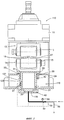
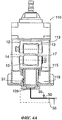
На фиг.1 на виде спереди показано правильное устройство согласно первому варианту осуществления настоящего изобретения. На фиг.2а, 2b, 2с проиллюстрирована последовательность действий при функционировании устройства с фиг.1.Figure 1 in front view shows the correct device according to the first embodiment of the present invention. On figa, 2b, 2C illustrates the sequence of actions during the operation of the device of figure 1.
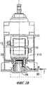
На фиг.3 показано правильное устройство согласно второму варианту осуществления настоящего изобретения.Figure 3 shows the correct device according to the second embodiment of the present invention.
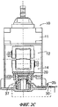
На фиг.4а, 4b, 4с проиллюстрирована последовательность действий при функционировании устройства на фиг.3.On figa, 4b, 4C illustrates the sequence of actions during the operation of the device in figure 3.
Для упрощения понимания были использованы одинаковые номера позиций, где это возможно, для обозначения на чертежах общих элементов. Следует понимать, что элементы и признаки одного варианта осуществления легко могут быть включены в другие варианты осуществления без дальнейших пояснений.To simplify the understanding, the same item numbers were used, where possible, to indicate common elements in the drawings. It should be understood that the elements and features of one embodiment can easily be incorporated into other embodiments without further explanation.
Осуществление изобретенияThe implementation of the invention
На фиг.1 и фиг.3 соответственно показано два варианта осуществления предлагаемого правильного устройства 10, 110.Figure 1 and figure 3, respectively, shows two embodiments of the proposed
Устройство 10, 110 содержит несущую конструкцию 11, к которой прикреплен верхний роликовый блок 12, имеющий верхний ролик 13 вогнутой гиперболической формы и соответствующую подушку 113, и нижний роликовый блок 14, имеющий нижний ролик 15 выпуклой гиперболической формы и соответствующую подушку 115. Роликовые блоки 12, 14 расположены напротив друг друга и ограничивают промежуточное пространство, или проход, 17 с регулируемым размером, через которое пропускают длинномерное металлическое изделие 18, которому необходимо придать окончательные размеры, находящиеся в пределах заданных допусков.The
Верхний роликовый блок 12 с соответствующим верхним роликом 13 установлен с возможностью движения вертикально в обоих направлениях на этапе начальной установки. Движение верхнего роликового блока 12 может быть осуществлено вручную или автоматически, предпочтительно посредством механической системы, например, винтов, кулачков, зубчатых передач или других подходящих средств, что не столь важно для достижения поставленных в настоящем изобретении задач.The
Также возможно использование электрических, гидродинамических, комбинированных систем или систем других типов.It is also possible to use electrical, hydrodynamic, combined systems or other types of systems.
Таким образом, этап начальной установки, на котором задают номинальный размер прохода 17 для изделия 18, осуществляют, перемещая верхний роликовый блок 12 относительно нижнего роликового блока 14, удерживаемого в максимально поднятом положении, что будет более подробно объяснено далее.Thus, the initial installation phase, at which the nominal size of the
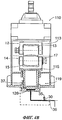
Нижний роликовый блок 14 соединен с гидравлическим приводом, который в варианте осуществления, показанном на фиг.1, обозначен номером позиции 19.The
Гидравлический привод 19 содержит подвижную часть или поршень, обозначенную номером 27 и соединенную с нижним роликовым блоком 14, и неподвижную часть, закрепленную на несущей конструкции 11 или другой неподвижной части, например, станине. Указанные две части привода разделены гидравлической камерой 26, выполненной с возможностью выборочного заполнения гидравлической жидкостью / выпуска гидравлической жидкости, подаваемой через трубку 30, вдоль которой расположен клапан 36, приводимый в действие, как объяснено далее.The
Подвижная часть 27 содержит в качестве основных компонентов: опору 20, непосредственно прикрепленную к нижнему роликовому блоку 14, промежуточную втулку 22, нижняя поверхность которой находится в непосредственном контакте с верхней поверхностью камеры 26, первую металлическую трубу 23, содержащую указанную промежуточную втулку 22, и вторую металлическую трубу 24, расположенную внутри первой металлической трубы 23.The
Неподвижная часть содержит третью опорную металлическую трубу 29 и верхнюю закрывающую плиту 28, изготовленную из материала, пригодного для нахождения в контакте с маслом. При этом верхняя поверхность указанной плиты находится в непосредственном контакте с нижней поверхностью камеры 26. Масло вводят в камеру 26 под высоким давлением через гидравлическую трубку 30 для постепенного заполнения указанной камеры, преодолевая силу тяжести нижнего роликового блока 14 и перемещая его вверх.The fixed part comprises a third support metal pipe 29 and an
Движение вверх нижнего роликового блока 14 происходит постепенно из нижнего положения (фиг.2а) в максимально верхнее положение хода (фиг.2b), заданное механическим путем за счет того, что зубец 33, выдающийся в направлении к наружной поверхности первой металлической трубы 23, упирается в неподвижную нажимную крышку, ограничивающую сверху полость 34, в которой зубец 33 может перемещаться в вертикальном направлении. После достижения указанного положения нижний ролик 15 занимает свое номинальное рабочее положение (фиг.2b), относительно которого регулируемое положение верхнего ролика 13 ограничивает размер прохода 17, установленного для выбранного обрабатываемого длинномерного изделия 18.The upward movement of the
При этом давление масла внутри камеры 26 составляет около 100 бар и способно достичь максимального значения около 130 бар.The oil pressure inside the
В варианте, показанном на фиг.1, предусмотрен датчик 35 давления, расположенный на подающей трубке 30, а также датчик 37 положения, соединенный с первой металлической трубой 23.In the embodiment shown in FIG. 1, a
Во время нормального функционирования правильного устройства 10 датчик 35 давления и датчик 37 положения определяют, соответственно, давление гидравлической жидкости в камере 26 и положение нижнего роликового блока 14 относительно номинального установленного положения.During the normal functioning of the
Если измеренные значения отличаются от предварительно заданных допусков относительно номинальных значений, другими словами, если давление масла превышает предварительно заданное пороговое значение, или положение нижнего роликового блока 14 сильно отклонилось относительно заданных допусков, вследствие прохождения изделия 18, размеры которого выходят за пределы допусков или которое имеет слишком овальную форму, то датчик 35 давления и/или датчик 37 положения отправляют команду на открытие клапана 36.If the measured values differ from the preset tolerances with respect to the nominal values, in other words, if the oil pressure exceeds a predetermined threshold value, or the position of the
Когда клапан 36 открыт, масло вытекает из камеры 26 через ту же подающую трубку 30 и выходит через отводящую линию 48.When the
В этом случае давление, оказываемое обрабатываемым изделием 18, совместно с весом нижнего роликового блока 14 обеспечивают опускание всего нижнего роликового блока 14, что позволяет сохранить целостность машины.In this case, the pressure exerted by the
Диаметр гидравлической камеры 26 меньше ширины правильных роликов 13 и 15 (составляет от 0,45 до 0,75 их ширины), так что количество масла, которое следует вывести, достаточно мало. В результате время реакции предохранительного устройства преимущественно становится меньше, а давление внутри камеры при этом находится в пределах заданного диапазона.The diameter of the
Подвижная часть системы, состоящая из опоры 20, втулки 22, первой металлической трубы 23 и второй металлической трубы 24, направленно перемещается посредством третьей металлической опорной трубы 29 и вмещающего элемента 39, выполненного за одно целое с конструкцией 11, что обеспечивает устойчивость и жесткость системы.The movable part of the system, consisting of a
Наличие камеры 26 непосредственно под втулкой 22 и, следовательно, под нижним роликом 15 обеспечивает возможность легкого доступа сверху для выполнения работ по техническому обслуживанию и ремонту или других действий, также с использованием той же механической системы для перемещения верхнего ролика 13. Благодаря этому отпадает необходимость применения крана или других подвижных средств, при этом обеспечивается большая безопасность, практичность и скорость выполнения операций по замене деталей или техническому обслуживанию и ремонту. Более того, поскольку доступ к камере 26 происходит сверху, настоящее изобретение позволяет избежать формирования ямы или других строительных работ под устройством, при этом операции по техническому обслуживанию, ремонту и замене деталей производятся в безопасных, комфортных условиях при хорошем освещении для операторов.The presence of the
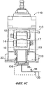
В альтернативном варианте осуществления изобретения, показанном на фиг.3, для одинаковых или эквивалентных элементов использованы те же номера позиций. Гидравлический привод 119 имеет подвижную часть, содержащую опору 20, выполненную за одно целое с нижним роликовым блоком 14, и поршень 127. Поршень 127, в свою очередь, состоит из первой металлической трубы 123, прикрепленной своей нижней частью к фланцу 38, а своей верхней частью - к указанной опоре 20.In the alternative embodiment of FIG. 3, the same reference numbers are used for the same or equivalent elements. The
Неподвижная часть гидравлического привода 119, между тем, содержит вмещающий элемент 39, выполненный за одно целое с конструкцией 11, причем боковые стенки указанного вмещающего элемента находятся в контакте с зонами, обозначенными номером 42, и действуют в качестве направляющих для первой металлической трубы 123 поршня 127, и нижний фланец 40, образующий дно гидравлического привода 119 и выполненный за одно целое с указанным вмещающим элементом 39.The fixed part of the
Камера 126 установлена между фланцем 38 (то есть дном подвижной части гидравлического привода 119) и фланцем 40 (то есть дном неподвижной части гидравлического привода 119), причем указанная камера 126 гидравлически соединена с маслоподающей трубкой 30 через канал, выполненный в нижнем фланце 40. В частности, верхняя поверхность камеры 126 находится в непосредственном контакте с нижней поверхностью фланца 38, а нижняя поверхность камеры 126 находится в непосредственном контакте с верхней поверхностью фланца 40.The
Подобно тому, что мы видели ранее, маслоподающая система обеспечивает подачу масла в камеру 126, в зависимости от степени открытия клапана, для постепенного поднятия нижнего роликового блока 14 (фиг.4а) до тех пор, пока камера 126 полностью не заполнится, а нижний роликовый блок 14 не придет в свое устойчивое, максимально поднятое рабочее положение (фиг.4b), ограниченное механическим упором зубца 33, вдвигаемого в полость 34.Similar to what we saw earlier, the oil supply system supplies oil to the
Положение верхнего роликового блока 13 относительно нижнего роликового блока 14 можно регулировать механически, как уже было показано выше, для задания значения номинального размера прохода для обрабатываемого изделия 18.The position of the
В данном варианте также предусмотрены датчик 35 давления и датчик 37 положения для определения, соответственно, давления масла в камере 126 и положения нижнего роликового блока 14 во время работы.In this embodiment, a
Когда датчик 35 давления и/или датчик 37 положения обнаруживают изменение давления или положения, которое превышает допустимое значение, клапан 36 открывается для выпуска масла в отводящую линию 48.When the
Выпуск масла обеспечивает незамедлительное опускание нижнего роликового блока под действием как его собственного веса, так и давления, оказываемого на него обрабатываемым изделием 18, что позволяет сохранить целостность конструкции машины.The release of oil provides an immediate lowering of the lower roller block under the action of both its own weight and the pressure exerted on it by the processed
Из приведенного выше описания двух вариантов осуществления настоящего изобретения можно увидеть, что изобретение позволяет получить множество преимуществ с точки зрения обеспечения оперативной, конструктивной и функциональной простоты.From the above description of two embodiments of the present invention, it can be seen that the invention provides many advantages in terms of providing operational, constructive and functional simplicity.
Благодаря использованию привода одинарного действия, а не привода двойного действия упрощается вся конструкция машины и реакция в случае перегрузок происходит быстрее.By using a single-acting drive rather than a double-acting drive, the entire machine structure is simplified and the reaction in the event of overloads is faster.
Использование собственного веса ролика для его опускания упрощает выполнение различных действий и уменьшает усилие, необходимое для его перемещения.Using the dead weight of the roller to lower it simplifies the implementation of various actions and reduces the force required to move it.
Вся гидравлическая схема сокращена до одной подающей трубки и клапана, выполненного с возможностью выборочного закрытия и открытия.The entire hydraulic circuit is reduced to a single supply pipe and valve, made with the possibility of selective closing and opening.
Движение и регулирование положения верхнего ролика происходит механически только на этапе начальной установки, после чего верхний ролик больше не принимает участие в процессе включения предохранительного/управляющего устройства.The movement and regulation of the position of the upper roller occurs mechanically only at the initial installation stage, after which the upper roller no longer takes part in the process of switching on the safety / control device.
Наконец, выполнение операций по техническому обслуживанию и ремонту гидравлического привода 19, 119 также упрощается, учитывая, что гидравлическая опора находится на высоте человеческого роста и, следовательно, до нее легко добраться, при этом указанная опора не расположена на еще большей высоте относительно верхнего роликового блока 12. В частности, в случае гидравлического привода 19, можно действовать сверху, сняв только нижний роликовый блок 14 и использовав для замены опоры 20 и втулки 22 механическую регулировочную систему верхнего роликового блока 12.Finally, the maintenance and repair of the
Очевидно, что в раскрытое выше правильное устройство 10, 110 можно вносить модификации и/или добавлять части, не выходя за пределы объема настоящего изобретения и области его использования.It is obvious that in the above
Claims (11)
Applications Claiming Priority (3)
| Application Number | Priority Date | Filing Date | Title |
|---|---|---|---|
| IT000108A ITUD20110108A1 (en) | 2011-07-11 | 2011-07-11 | HYPERBOLIC ROLLER STRAIGHTENING DEVICE FOR METALLIC PRODUCTS AND ITS PROCEDURE |
| ITUD2011A000108 | 2011-07-11 | ||
| PCT/IB2012/001356 WO2013008081A1 (en) | 2011-07-11 | 2012-07-10 | Straightening device with hyperbolic rolls for metal products and corresponding method |
Publications (2)
| Publication Number | Publication Date |
|---|---|
| RU2014104023A RU2014104023A (en) | 2015-08-20 |
| RU2575111C2 true RU2575111C2 (en) | 2016-02-10 |
Family
ID=
Citations (6)
| Publication number | Priority date | Publication date | Assignee | Title |
|---|---|---|---|---|
| SU250644A1 (en) * | Всесоюзный научно исследовательский институт металлургического | TWO-VALVE CORRECT MACHINE FOR CORRECTION OF PIPES AND RODKOVLLTE1! T! 10- TECHNICAL | ||
| US3933018A (en) * | 1973-10-03 | 1976-01-20 | Th. Kieserling & Albrecht | Method and apparatus for straightening end sections of elongated workpieces |
| SU889192A2 (en) * | 1977-08-22 | 1981-12-15 | За витель | Two-roll machine for straightening bars |
| US4763504A (en) * | 1981-07-06 | 1988-08-16 | Nilsson Einar W | Straightening machines and methods |
| RU2113305C1 (en) * | 1997-06-11 | 1998-06-20 | Открытое акционерное общество "УралЛУКтрубмаш" | Method for article straightening by rolls |
| DE19724300A1 (en) * | 1997-06-09 | 1998-12-10 | Wrt Metallbearbeitungsmaschine | Apparatus for pipe or bar straightening |
Patent Citations (6)
| Publication number | Priority date | Publication date | Assignee | Title |
|---|---|---|---|---|
| SU250644A1 (en) * | Всесоюзный научно исследовательский институт металлургического | TWO-VALVE CORRECT MACHINE FOR CORRECTION OF PIPES AND RODKOVLLTE1! T! 10- TECHNICAL | ||
| US3933018A (en) * | 1973-10-03 | 1976-01-20 | Th. Kieserling & Albrecht | Method and apparatus for straightening end sections of elongated workpieces |
| SU889192A2 (en) * | 1977-08-22 | 1981-12-15 | За витель | Two-roll machine for straightening bars |
| US4763504A (en) * | 1981-07-06 | 1988-08-16 | Nilsson Einar W | Straightening machines and methods |
| DE19724300A1 (en) * | 1997-06-09 | 1998-12-10 | Wrt Metallbearbeitungsmaschine | Apparatus for pipe or bar straightening |
| RU2113305C1 (en) * | 1997-06-11 | 1998-06-20 | Открытое акционерное общество "УралЛУКтрубмаш" | Method for article straightening by rolls |
Similar Documents
| Publication | Publication Date | Title |
|---|---|---|
| EP2614899B1 (en) | Press machine | |
| US7406851B2 (en) | Die cushion controlling apparatus and die cushion controlling method | |
| EP3412372B1 (en) | Die cushion device for a press machine comprisng a double blank detecting device | |
| US6595122B1 (en) | Slide inclination correcting method and slide inclination correcting apparatus in press machinery | |
| EP3184187A1 (en) | Die cushion device and method of controlling the die cushion device | |
| KR101268322B1 (en) | Rolling apparatus | |
| US7401488B2 (en) | Die cushion apparatus | |
| US7726168B2 (en) | Adjusting cylinders in rolling stands, including vertical edging stands | |
| KR950009141B1 (en) | Rolling mill and rolling mill operation method | |
| US20170129000A1 (en) | Method and apparatus for reducing cutting impact in a precision blanking press | |
| CN110539520B (en) | Double blank detection device for press and die protection device for press | |
| KR101535629B1 (en) | Straightening device with hyperbolic rolls for metal products and corresponding method | |
| RU2575111C2 (en) | Straightening device with hyperbolic rolls for metals and method implemented by said device | |
| RU2578862C1 (en) | Rolling mill stand and method of its installation, method of rolled stock with the help of stand | |
| JPH05248405A (en) | Pressurizer of working machine | |
| ITBS20080090A1 (en) | ANTI-FALL DEVICE PARTICULARLY FOR HYDRAULIC PRESSES | |
| RU2201307C2 (en) | Hydraulic drive for moving lower roll of four-roll sheet bending machine | |
| SU863031A1 (en) | Rolling stand | |
| CN111207121A (en) | Servo hydraulic device and servo hydraulic bending machine | |
| JPH10193197A (en) | Die protection apparatus and method for direct acting press | |
| JP2010089886A (en) | Stroke control method of hydraulic jack for demolition of structure | |
| JP2007144464A (en) | Hydraulic die spotting press | |
| JPH0551365B2 (en) | ||
| JPS623720B2 (en) | ||
| JPH0647414A (en) | Device for setting roll gap in rolling mill |