RU2573728C2 - Steam turbine system (versions) and method of its operation - Google Patents
Steam turbine system (versions) and method of its operation Download PDFInfo
- Publication number
- RU2573728C2 RU2573728C2 RU2011131171/06A RU2011131171A RU2573728C2 RU 2573728 C2 RU2573728 C2 RU 2573728C2 RU 2011131171/06 A RU2011131171/06 A RU 2011131171/06A RU 2011131171 A RU2011131171 A RU 2011131171A RU 2573728 C2 RU2573728 C2 RU 2573728C2
- Authority
- RU
- Russia
- Prior art keywords
- steam
- turbine
- seal
- pressure
- flow
- Prior art date
Links
Images

Classifications
-
- F—MECHANICAL ENGINEERING; LIGHTING; HEATING; WEAPONS; BLASTING
- F01—MACHINES OR ENGINES IN GENERAL; ENGINE PLANTS IN GENERAL; STEAM ENGINES
- F01D—NON-POSITIVE DISPLACEMENT MACHINES OR ENGINES, e.g. STEAM TURBINES
- F01D11/00—Preventing or minimising internal leakage of working-fluid, e.g. between stages
- F01D11/02—Preventing or minimising internal leakage of working-fluid, e.g. between stages by non-contact sealings, e.g. of labyrinth type
- F01D11/04—Preventing or minimising internal leakage of working-fluid, e.g. between stages by non-contact sealings, e.g. of labyrinth type using sealing fluid, e.g. steam
-
- F—MECHANICAL ENGINEERING; LIGHTING; HEATING; WEAPONS; BLASTING
- F05—INDEXING SCHEMES RELATING TO ENGINES OR PUMPS IN VARIOUS SUBCLASSES OF CLASSES F01-F04
- F05D—INDEXING SCHEME FOR ASPECTS RELATING TO NON-POSITIVE-DISPLACEMENT MACHINES OR ENGINES, GAS-TURBINES OR JET-PROPULSION PLANTS
- F05D2220/00—Application
- F05D2220/30—Application in turbines
- F05D2220/31—Application in turbines in steam turbines
-
- F—MECHANICAL ENGINEERING; LIGHTING; HEATING; WEAPONS; BLASTING
- F05—INDEXING SCHEMES RELATING TO ENGINES OR PUMPS IN VARIOUS SUBCLASSES OF CLASSES F01-F04
- F05D—INDEXING SCHEME FOR ASPECTS RELATING TO NON-POSITIVE-DISPLACEMENT MACHINES OR ENGINES, GAS-TURBINES OR JET-PROPULSION PLANTS
- F05D2240/00—Components
- F05D2240/55—Seals
Abstract
Description
Предпосылки создания изобретенияBACKGROUND OF THE INVENTION
Изобретение относится к технологии паровых турбин и, в частности, к направлению пара утечки для повышения производительности паровой турбины. Предлагается также соответствующий способ.The invention relates to technology for steam turbines and, in particular, to the direction of steam leakage to increase the performance of a steam turbine. An appropriate method is also proposed.
Система парового уплотнения предотвращает выход пара из паровой турбины и/или проникновение в нее воздуха через зазор между валом и корпусом турбины. Корпус паровой турбины оборудован уплотнением для управления потоком утечки вдоль вала. Обычно применяется уплотнение лабиринтового типа, содержащее ряд гребней, которые расположены так, чтобы с минимальным зазором подходить к вращающемуся валу. Малый зазор и конфигурация гребней обеспечивают сопротивление потоку, что минимизирует поток утечки вдоль вала.The steam seal system prevents steam from escaping from the steam turbine and / or air into it through the gap between the shaft and the turbine housing. The steam turbine housing is equipped with a seal to control leakage along the shaft. Typically, a labyrinth type seal is used, containing a series of ridges, which are arranged so as to fit with a minimum clearance to the rotating shaft. The small clearance and flange configuration provides resistance to flow, which minimizes leakage flow along the shaft.
Существуют два типа уплотнений: напорное уплотнение (pressure type) и вакуумное уплотнение (vacuum type). Напорное уплотнение предотвращает выход пара при положительном внутреннем давлении пара при полной нагрузке. При частичной нагрузке, когда в турбине имеется вакуум, уплотнение обеспечивает защиту от проникновения воздуха в турбину. В структурах с напорным уплотнением имеется утечка в коллектор парового уплотнения (steam seal header, SSH), давление в котором может регулироваться регулирующими клапанами парового уплотнения. Напорное уплотнение также может иметь одну или более утечек высокого давления, которые выпускаются в точки ввода пара на турбине. При полной нагрузке турбины пар утечки проходит из напорного уплотнения в коллектор парового уплотнения. При запуске и частичной нагрузке турбины пар проходит из коллектора парового уплотнения в уплотнение для защиты от проникновения наружного воздуха в турбины.There are two types of seals: pressure seal and vacuum type. The pressure seal prevents the escape of steam at positive internal steam pressure at full load. At partial load, when there is a vacuum in the turbine, the seal provides protection against air entering the turbine. Structures with a pressure seal have a leak in the steam seal header (SSH), the pressure of which can be regulated by steam seal control valves. The pressure seal may also have one or more high pressure leaks that are discharged to the steam inlet points on the turbine. When the turbine is fully loaded, leak steam passes from the pressure seal to the steam seal manifold. At start-up and partial load of the turbine, steam passes from the steam seal manifold into the seal to protect against the ingress of outside air into the turbines.
Вакуумное уплотнение всегда обеспечивает защиту против вакуума, независимо от нагрузки турбины. В вакуумное уплотнение должен подаваться пар из коллектора парового уплотнения. Крайняя часть как напорного уплотнения, так и у вакуумного уплотнения поддерживается под вакуумом системой откачки пара уплотнения (gland exhaust system, GES).The vacuum seal always provides protection against vacuum, regardless of the turbine load. Steam from the steam seal manifold must be supplied to the vacuum seal. The extreme part of both the pressure seal and the vacuum seal is maintained under vacuum by the gland exhaust system (GES).
Смесь пара из коллектора парового уплотнения и воздуха, втягиваемого через крайние уплотнительные кольца, выводится в конденсатор парового уплотнения для отвода тепла и сброса в главный конденсатор. Конденсатор парового уплотнения может содержать кожухотрубный теплообменник для конденсации пара и вентилятор с приводом от двигателя для удаления воздуха и поддержания вакуума в системе.A mixture of steam from the steam seal manifold and air drawn through the outermost sealing rings is discharged into the steam seal condenser to remove heat and discharge into the main condenser. The steam seal condenser may include a shell-and-tube heat exchanger for condensing steam and a fan driven by a motor to remove air and maintain a vacuum in the system.
Питательный клапан парового уплотнения (steam seal feed valve, SSFV) и клапан сброса давления парового уплотнения (steam seal dump valve, SSDV) служат для управления давлением в коллекторе парового уплотнения во всех режимах работы турбины, от проворачивания вала до полной нагрузки. Система управления турбиной может контролировать давление в коллекторе SSH и размещать клапаны для поддержания давления в коллекторе в требуемом диапазоне. При запуске вся паровая турбина находится под вакуумом. Все уплотнения турбины требуют ввода в них пара из коллектора парового уплотнения. Пар из внешнего источника (обычно вспомогательного котла) подается в коллектор SSH под управлением клапана SSFV. Во время этой операции клапан SSDV закрыт.The steam seal feed valve (SSFV) and the steam seal dump valve (SSDV) are used to control the pressure in the steam seal manifold in all turbine operating modes, from cranking to full load. The turbine control system can monitor the pressure in the SSH manifold and place valves to maintain manifold pressure in the desired range. When starting up, the entire steam turbine is under vacuum. All turbine seals require steam to be introduced into them from the steam seal manifold. Steam from an external source (usually an auxiliary boiler) is supplied to the SSH collector under the control of the SSFV valve. During this operation, the SSDV is closed.
Поток к напорному уплотнению обычно уменьшается пропорционально нагрузке турбины до тех пор, пока направление потока не изменится на обратное, когда поток начнет подавать пар в коллектор SSH. Поток в вакуумные уплотнения приблизительно постоянен независимо от нагрузки. Точка нагрузки, при которой поток от напорных уплотнений равен потоку в вакуумные уплотнения, называется точкой самоуплотнения. Когда нагрузка увеличивается выше точки самоуплотнения, клапан SSDV устанавливается в открытое положение для управления давлением в коллекторе SSH, сбрасывая избыточный пар в главный конденсатор при уже закрытом клапане SSFV. В этом состоянии внешний источник пара отсоединен с помощью закрытия клапана SSFV.The flow to the pressure seal usually decreases proportionally to the turbine load until the flow direction reverses when the flow begins to supply steam to the SSH manifold. The flow to the vacuum seals is approximately constant regardless of the load. The point of loading at which the flow from the pressure seals is equal to the flow into the vacuum seals is called the self-sealing point. When the load rises above the self-sealing point, the SSDV is set to open to control the pressure in the SSH manifold, dumping excess steam into the main condenser when the SSFV is already closed. In this state, the external steam source is disconnected by closing the SSFV valve.
Может предоставляться дополнительный канал утечки на стороне высокого давления уплотнения вала для стороны впуска турбины высокого давления (high pressure, HP), стороны выпуска турбины HP и стороны впуска турбины среднего давления (intermediate pressure, IP). Соответствующие линии утечки могут быть функционально связаны для доставки пара утечки в различные места паротурбинной системы для использования его при выработке электроэнергии. Этот пар утечки может подаваться к таким местам, как вертикальное соединение между турбинами IP/LP, труба впуска пара турбины LP и ступени кожуха одной из турбин HP, IP и LP.An additional leakage channel may be provided on the high pressure side of the shaft seal for the inlet side of the high pressure turbine (HP), the outlet side of the HP turbine and the inlet side of the medium pressure turbine (IP). Corresponding leak lines can be functionally connected to deliver leak steam to various places in the steam turbine system for use in power generation. This leak steam can be delivered to places such as the vertical connection between the IP / LP turbines, the LP turbine steam inlet pipe and the casing steps of one of the HP, IP and LP turbines.
Ближайшим аналогом настоящего изобретения согласно независимому пункту 1 формулы изобретения является паротурбинная система, описанная в патенте США №7,040,861 В2, МПК F01D 11/00, выданном 09.05.2006 г. В данном патенте описана паротурбинная система, которая содержит турбину высокого давления, функционально связанную с турбиной среднего давления и турбиной низкого давления. Рабочий пар проходит через турбину высокого давления, и/или турбину среднего давления, и/или турбину низкого давления. Канал утечки проходит от напорного уплотнения вблизи одной или обеих турбин высокого и среднего давления. Пар утечки, проходящий через канал утечки, соединен с потоком рабочего пара внутри паротурбинной системы. Линии парового уплотнения от напорного уплотнения на одной или обеих турбинах высокого давления и среднего давления связаны с коллектором парового уплотнения. Указанный коллектор связан с вакуумным уплотнением на турбине низкого давления и сконфигурирован для сохранения постоянного самоподдерживающегося давления в вакуумном уплотнении турбины низкого давления.The closest analogue of the present invention according to the independent claim 1 is a steam turbine system described in US Pat. No. 7,040,861 B2, IPC F01D 11/00, issued May 5, 2006. This patent describes a steam turbine system that comprises a high pressure turbine operably associated with medium pressure turbine and low pressure turbine. The working steam passes through a high pressure turbine and / or a medium pressure turbine and / or a low pressure turbine. A leak channel extends from the pressure seal near one or both of the high and medium pressure turbines. Leakage steam passing through the leakage channel is connected to the flow of working steam inside the steam turbine system. The steam seal lines from the pressure seal on one or both high pressure and medium pressure turbines are connected to the steam seal manifold. The specified manifold is associated with a vacuum seal on the low pressure turbine and is configured to maintain a constant self-sustaining pressure in the vacuum seal of the low pressure turbine.
В описанной конструкции отсутствует средство для ограничения потока уплотнительного пара, т.е. отсутствует функциональная связь с линиями парового уплотнения, и, следовательно, данная система не обеспечивает возможности подачи потока пара утечки в поток рабочего пара для полезной работы в указанной системе.In the described construction there is no means for restricting the flow of sealing vapor, i.e. there is no functional connection with the steam seal lines, and therefore, this system does not provide the possibility of supplying a leakage steam stream to the working steam stream for useful work in the specified system.
Ближайшим аналогом настоящего изобретения согласно независимому пункту 12 формулы изобретения является паротурбинная система, описанная в патенте США №7,040,861 В2, МПК F01D 11/00, выданном 09.05.2006 г. В указанном документе предлагается паротурбинная система, включающая по меньшей мере первую паровую турбину, функционально связанную с турбиной низкого давления, при этом паротурбинная система переходит в режим самоуплотнения при определенном уровне нагрузки системы. Имеется канал потока рабочего пара внутри первой паровой турбины и турбины. Канал утечки от напорного уплотнения вблизи первой паровой турбины связан с потоком рабочего пара внутри паротурбинной системы.The closest analogue of the present invention according to the independent claim 12 is a steam turbine system described in US Pat. No. 7,040,861 B2, IPC F01D 11/00, issued May 5, 2006. A steam turbine system including at least a first steam turbine is provided functionally. associated with the low pressure turbine, while the steam turbine system goes into self-sealing mode at a certain level of system load. There is a channel for the flow of working steam inside the first steam turbine and turbine. The leak channel from the pressure seal near the first steam turbine is connected to the flow of working steam inside the steam turbine system.
В указанной системе отсутствует коллектор парового уплотнения, таким образом, данная конструкция не обеспечивает возможности сохранения постоянного самоподдерживающегося давления в уплотнении турбины.The specified system does not have a steam seal manifold; therefore, this design does not provide the possibility of maintaining a constant self-sustaining pressure in the turbine seal.
В описанной конструкции также отсутствует средство для ограничения потока уплотнительного пара, т.е. отсутствует функциональная связь с линиями парового уплотнения, и, следовательно, данная система не обеспечивает возможности подачи потока пара утечки в поток рабочего пара для полезной работы в указанной системе. В указанной паротурбинной системе отсутствует контроллер, т.е. указанная конструкция не обеспечивает возможности управления средством ограничения в зависимости от состояния потока уплотнительного пара паротурбинной системы.The described construction also lacks a means for restricting the flow of sealing vapor, i.e. there is no functional connection with the steam seal lines, and therefore, this system does not provide the possibility of supplying a leakage steam stream to the working steam stream for useful work in the specified system. In the specified steam turbine system there is no controller, i.e. the specified design does not provide the ability to control the restriction tool depending on the state of the flow of the sealing steam of the steam turbine system.
Ближайшим аналогом настоящего изобретения согласно независимому пункту 17 формулы изобретения является способ работы паротурбинной системы, описанный в патенте США №7,040,861 В2, МПК F01D 11/00, выданном 09.05.2006 г. Из указанного патента известен способ управления паротурбинной системой. Способ включает обеспечение наличия турбины высокого давления, функционально связанной с турбиной среднего давления и турбиной низкого давления. Линия утечки соединяет одно или более напорных уплотнений турбины высокого давления и турбины среднего давления с потоком рабочего пара внутри турбинной системы.The closest analogue of the present invention according to the independent claim 17 of the claims is a method of operating a steam turbine system described in US patent No. 7,040,861 B2, IPC F01D 11/00, issued May 09, 2006. A method for controlling a steam turbine system is known from this patent. The method includes providing a high pressure turbine operably coupled to a medium pressure turbine and a low pressure turbine. A leak line connects one or more pressure seals of the high pressure turbine and medium pressure turbine to the flow of working steam within the turbine system.
В указанном способе отсутствует коллектор парового уплотнения, таким образом, данный способ не обеспечивает режима самоуплотнения, т.е. сохранения постоянного самоподдерживающегося давления уплотнения в турбине высокого давления, турбине среднего давления и турбине низкого давления. В указанном способе также отсутствуют этап ограничения потока уплотнительного пара турбины высокого давления и/или турбины среднего давления и этап направления избыточного уплотнительного пара в поток рабочего пара паротурбинной системы. Таким образом, данный способ не обеспечивает подачу пара утечки от уплотнений к местам в турбинной системе, соответственно не обеспечивается возможность увеличения выходной мощности системы.In this method, there is no steam seal manifold, thus, this method does not provide a self-sealing mode, i.e. maintaining a constant, self-sustaining seal pressure in the high pressure turbine, medium pressure turbine, and low pressure turbine. The specified method also lacks the step of restricting the sealing steam flow of the high pressure turbine and / or medium pressure turbine and the step of directing excess sealing steam into the working steam flow of the steam turbine system. Thus, this method does not provide the supply of leakage steam from the seals to places in the turbine system, respectively, it is not possible to increase the output power of the system.
Современные системы парового уплотнения имеют неоптимальную конструкцию с одной уставкой. Например, эти конструкции турбинной установки, описанной выше, могут обеспечивать точку нагрузки в режиме самоуплотнения (self-sealing load point, SSLP) приблизительно 30-45%. Выражение «паровая турбина находится в режиме самоуплотнения», как правило, относится к состоянию, в котором поток пара от напорного уплотнения достаточен для создания давления и вакуумных уплотнений. Однако в условиях более высокой нагрузки поток пара напорного уплотнения, проходящий к коллектору парового уплотнения, увеличивается, а требования для вакуумных уплотнений остаются приблизительно постоянными. Поэтому дополнительный пар, приходящий от напорных уплотнений в систему парового уплотнения, может сбрасываться в конденсатор с использованием клапана SSDV без выполнения полезной работы.Modern steam seal systems have a non-optimal design with one set point. For example, these turbine plant designs described above can provide a self-sealing load point (SSLP) of about 30-45%. The expression “steam turbine is in self-sealing mode” generally refers to a state in which the steam flow from the pressure seal is sufficient to create pressure and vacuum seals. However, under higher load conditions, the vapor seal flow of the pressure seal passing to the steam seal manifold increases, and the requirements for vacuum seals remain approximately constant. Therefore, additional steam coming from pressure seals to the steam seal system can be discharged into the condenser using the SSDV valve without doing any useful work.
Паровые турбины являются относительно зрелой технологией, повышение производительности которой имеет большое значение на рынке. Улучшения рабочих характеристик с минимальными дополнительными затратами желательны с точки зрения конкурентоспособности.Steam turbines are a relatively mature technology, and increasing their productivity is of great importance in the market. Performance improvements at the lowest possible cost are desirable in terms of competitiveness.
Краткое описание изобретенияSUMMARY OF THE INVENTION
Предлагаются система и способ для увеличения выходной мощности и коэффициента полезного действия цикла паровой турбины (steam turbine, ST) путем уменьшения утечки пара в коллектор парового уплотнения (SSH), который прежде сбрасывался в конденсатор как избыточный пар во время работы с нагрузкой выше состояния самоуплотнения. Линия утечки высококачественного пара от напорного уплотнения турбин HP и IP в коллектор SSH может быть блокирована путем добавления в нее препятствий потоку и путем управления потоком уплотнительного пара. Для увеличения выходной мощности поток пара утечки направляется в расположенные вниз по течению ступени линии расширения пара, тем самым обеспечивая преимущество, в коэффициенте полезного действия и выходной мощности.A system and method are proposed for increasing the output power and efficiency of a steam turbine (ST turbine) cycle by reducing steam leakage into the steam seal manifold (SSH), which was previously dumped into the condenser as excess steam during operation with a load above the self-sealing state. The high-quality steam leakage line from the pressure seal of the HP and IP turbines to the SSH manifold can be blocked by blocking the flow and controlling the flow of the sealing steam. To increase the output power, the leakage steam flow is directed to the downstream steps of the steam expansion line, thereby providing an advantage in the efficiency and output power.
В первом аспекте данного изобретения предлагается паротурбинная система, которая содержит турбину высокого давления (HP), функционально связанную с турбиной среднего давления (IP) и турбиной низкого давления (LP). Рабочий пар проходит через турбину HP, и/или турбину IP, и/или турбину LP. Канал утечки проходит от напорного уплотнения вблизи одной или обеих турбин HP и IP. Пар утечки, проходящий через канал утечки, соединен с потоком рабочего пара внутри паротурбинной системы. Линии парового уплотнения от напорного уплотнения на одной или обеих турбинах HP и IP связаны с коллектором парового уплотнения (SSH). Коллектор SSH связан с вакуумным уплотнением на турбине LP и сконфигурирован для сохранения постоянного самоподдерживающегося давления в вакуумном уплотнении турбины LP. Предлагаются средства для ограничения потока уплотнительного пара, функционально связанные с одной или более линиями парового уплотнения между напорным уплотнением для турбин HP и IP и коллектором SSH.In a first aspect of the present invention, there is provided a steam turbine system that comprises a high pressure turbine (HP) operably coupled to a medium pressure turbine (IP) and a low pressure turbine (LP). Working steam passes through an HP turbine and / or an IP turbine and / or an LP turbine. A leak channel extends from the pressure seal near one or both of the HP and IP turbines. Leakage steam passing through the leakage channel is connected to the flow of working steam inside the steam turbine system. The steam seal lines from the pressure seal on one or both of the HP and IP turbines are connected to the steam seal manifold (SSH). The SSH manifold is connected to the vacuum seal on the LP turbine and is configured to maintain a constant, self-sustaining pressure in the vacuum seal of the LP turbine. Means are proposed for restricting the flow of sealing vapor, functionally coupled to one or more steam seal lines between the pressure seal for HP and IP turbines and the SSH manifold.
Предпочтительно, канал утечки от напорного уплотнения вблизи турбины высокого давления и/или турбины среднего давления включает напорное уплотнение на стороне впуска пара турбины высокого давления, напорное уплотнение на стороне выпуска пара турбины высокого давления и напорное уплотнение на стороне впуска пара турбины среднего давления, связанные с коллектором парового уплотнения, сконфигурированным для сохранения постоянного самоподдерживающегося давления уплотнения в уплотнении турбины низкого давления.Preferably, the leak path from the pressure seal in the vicinity of the high pressure turbine and / or medium pressure turbine includes a pressure seal on the steam inlet side of the high pressure turbine, a pressure seal on the steam outlet side of the high pressure turbine, and a pressure seal on the steam inlet side of the medium pressure turbine a steam seal manifold configured to maintain a constant, self-sustaining seal pressure in the low pressure turbine seal.
Преимущественно, указанная паротурбинная система содержит контроллер, сконфигурированный для отделения избыточного уплотнительного пара от коллектора парового уплотнения.Advantageously, said steam turbine system comprises a controller configured to separate excess sealing steam from the steam seal manifold.
Предпочтительно, средство для ограничения потока уплотнительного пара приводится в действие контроллером согласно последовательности отделения потока уплотнительного пара от стороны впуска высокого давления, стороны выпуска высокого давления, стороны впуска среднего давления, стороны выпуска среднего давления и стороны впуска низкого давления.Preferably, the means for restricting the flow of the sealing steam is driven by the controller according to the sequence for separating the flow of the sealing steam from the high pressure inlet side, the high pressure discharge side, the medium pressure inlet side, the medium pressure discharge side and the low pressure inlet side.
Преимущественно, указанная паротурбинная система содержит систему управления турбиной, включающую сигнал нагрузки турбины, при этом средство для ограничения потока уплотнительного пара приводится в действие контроллером согласно сигналу нагрузки турбины от контроллера турбины.Advantageously, said steam-turbine system comprises a turbine control system including a turbine load signal, wherein means for restricting the flow of sealing steam is driven by the controller according to the turbine load signal from the turbine controller.
Во втором аспекте данного изобретения предлагается паротурбинная система, включающая по меньшей мере первую паровую турбину, функционально связанную с турбиной низкого давления (LP), при этом паротурбинная система переходит в режим самоуплотнения при определенном уровне нагрузки системы.In a second aspect of the present invention, there is provided a steam turbine system comprising at least a first steam turbine operably coupled to a low pressure turbine (LP), wherein the steam turbine system goes into self-sealing mode at a certain level of system load.
Имеется канал потока рабочего пара внутри первой паровой турбины и турбины LP.There is a working steam flow channel inside the first steam turbine and LP turbine.
Канал утечки от напорного уплотнения вблизи первой паровой турбины связан с потоком рабочего пара внутри паротурбинной системы. Одна или более линий парового уплотнения от напорного уплотнения на первой паровой турбине соединены с коллектором парового уплотнения (SSH). Коллектор SSH соединен с вакуумным уплотнением на турбине LP и сконфигурирован для сохранения постоянного самоподдерживающегося давления уплотнения в уплотнении турбины LP. Средства для ограничения потока уплотнительного пара функционально связаны по меньшей мере с одной из линий парового уплотнения между первой паровой турбиной и коллектором SSH. Предусмотрен контроллер, реагирующий на состояние потока уплотнительного пара паротурбинной системы. Контроллер запускает средство для ограничения потока уплотнительного пара так, чтобы предпочтительно подавать поток пара утечки в поток рабочего пара.The leak channel from the pressure seal near the first steam turbine is connected to the flow of working steam inside the steam turbine system. One or more steam seal lines from the pressure seal on the first steam turbine are connected to a steam seal manifold (SSH). The SSH manifold is connected to the vacuum seal on the LP turbine and is configured to maintain a constant, self-sustaining seal pressure in the LP turbine seal. Means for restricting the flow of sealing steam are operatively coupled to at least one of the steam seal lines between the first steam turbine and the SSH manifold. A controller is provided that responds to the state of the seal steam flow of the steam turbine system. The controller launches means for restricting the flow of the sealing vapor so that it is preferable to supply a leakage steam stream to the working steam stream.
В другом аспекте данного изобретения предлагается способ управления паротурбинной системой для увеличения выходной мощности. Способ включает обеспечение наличия турбины высокого давления (HP), функционально связанной с турбиной среднего давления (IP) и турбиной низкого давления (LP). Линия утечки соединяет одно или более напорных уплотнений турбины HP и турбины IP с потоком рабочего пара внутри турбинной системы, тем самым обеспечивая большую выходную мощность. Способ включает сохранение постоянного самоподдерживающегося давления уплотнения в турбине HP, турбине IP и турбине LP через соединения с коллектором парового уплотнения (SSH), при этом коллектор парового уплотнения содержит питательный клапан парового уплотнения от вспомогательного источника подачи пара и клапана сброса давления парового уплотнения в сток пара. Способ включает также ограничение потока уплотнительного пара турбины HP и/или турбины IP в коллектор SSH в режиме самоуплотнения паротурбинной системы. Способ также включает предпочтительное направление избыточного уплотнительного пара, ограниченного в направлении от турбин HP и IP к коллектору SSH, в поток рабочего пара паротурбинной системы в режиме самоуплотнения паротурбинной системы.In another aspect of the present invention, there is provided a method for controlling a steam turbine system to increase power output. The method includes providing a high pressure turbine (HP) operably coupled to a medium pressure turbine (IP) and a low pressure turbine (LP). A leak line connects one or more pressure seals of the HP turbine and IP turbine with the flow of working steam inside the turbine system, thereby providing greater power output. The method includes maintaining a constant, self-sustaining seal pressure in the HP turbine, IP turbine, and LP turbine through connections to the steam seal manifold (SSH), wherein the steam seal manifold comprises a steam seal feed valve from an auxiliary steam supply source and a steam seal pressure relief valve to the steam drain . The method also includes restricting the flow of the sealing steam of the HP turbine and / or IP turbine into the SSH manifold in the self-sealing mode of the steam turbine system. The method also includes the preferred direction of the excess sealing steam, limited in direction from the HP and IP turbines to the SSH manifold, into the working steam stream of the steam turbine system in the self-sealing mode of the steam turbine system.
Предпочтительно, шаг ограничения потока уплотнительного пара включает блокирование потока парового уплотнения от коллектора парового уплотнения диафрагмами и/или изолирующими клапанами и/или дроссельными клапанами.Preferably, the step of restricting the flow of the sealing vapor includes blocking the flow of the steam seal from the steam seal manifold by diaphragms and / or isolation valves and / or throttle valves.
Преимущественно, шаг блокирования включает управление положением изолирующих клапанов и/или дроссельных клапанов с помощью подачи сигналов от контроллера.Advantageously, the blocking step includes controlling the position of the isolation valves and / or throttle valves by supplying signals from the controller.
Предпочтительно, шаг управления включает определение режима самоуплотнения в коллекторе парового уплотнения и передачу сигналов о положении изолирующих клапанов и/или дроссельных клапанов.Preferably, the control step includes determining a self-sealing mode in the steam seal manifold and signaling the position of the isolation valves and / or throttle valves.
Краткое описание чертежейBrief Description of the Drawings
Эти и другие отличительные признаки предлагаемого изобретения станут более понятными из последующего подробного описания различных аспектов изобретения и прилагаемых чертежей, иллюстрирующих различные формы его осуществления.These and other features of the invention will become more apparent from the following detailed description of various aspects of the invention and the accompanying drawings, illustrating various forms of its implementation.
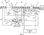
На фиг. 1 показана структурная схема паротурбинной системы согласно формам осуществления изобретения.In FIG. 1 shows a block diagram of a steam turbine system according to embodiments of the invention.
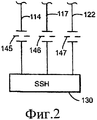
На фиг. 2 проиллюстрированы диафрагмы, используемые в качестве средства для направления потока избыточного уплотнительного пара в поток рабочего пара.In FIG. 2 illustrates diaphragms used as means for directing the flow of excess sealing steam into the flow of working steam.
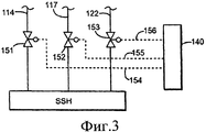
На фиг. 3 проиллюстрированы изолирующие клапаны, управляемые контроллером уплотнительного пара и используемые в качестве средства для направления потока избыточного уплотнительного пара в поток рабочего пара.In FIG. 3 illustrates isolation valves controlled by a sealing steam controller and used as a means to direct the flow of excess sealing steam into the working steam stream.
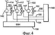
На фиг. 4 проиллюстрированы изолирующие клапаны, управляемые контроллером уплотнительного пара в комбинации с диафрагмами, используемыми в качестве средства для направления потока избыточного уплотнительного пара в поток рабочего пара.In FIG. 4 illustrates isolation valves controlled by a sealing steam controller in combination with diaphragms used as means for directing excess sealing steam into a working steam stream.
На фиг. 5 проиллюстрированы дроссельные клапаны, управляемые контроллером уплотнительного пара и используемые в качестве средства для направления потока избыточного уплотнительного пара в поток рабочего пара.In FIG. 5 illustrates throttle valves controlled by a sealing steam controller and used as a means to direct the flow of excess sealing steam into the working steam stream.
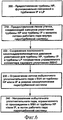
На фиг. 6 показана блок-схема способа предпочтительного направления потока избыточного уплотнительного пара в поток рабочего пара.In FIG. 6 is a flowchart of a method for preferably directing a stream of excess sealing steam into a working steam stream.
Следует отметить, что чертежи выполнены не в масштабе. Чертежи предназначены для иллюстрации только основных аспектов изобретения и поэтому не должны рассматриваться как ограничение изобретения. На чертежах аналогичная нумерация представляет аналогичные элементы.It should be noted that the drawings are not to scale. The drawings are intended to illustrate only the main aspects of the invention and therefore should not be construed as limiting the invention. In the drawings, a similar numbering represents similar elements.
Подробное описание изобретенияDETAILED DESCRIPTION OF THE INVENTION
Данное изобретение имеет много преимуществ, включая предоставление турбинной системы, в которой во время режима проектной или максимальной нагрузки избыточный пар утечки блокируется от сброса коллектором парового уплотнения и отводится в поток рабочего пара, что увеличивает полезную мощность и эффективность турбинной системы. Кроме того, ограничение пара утечки, сбрасываемого коллектором парового уплотнения в конденсатор, позволяет уменьшить нагрузку на конденсатор.This invention has many advantages, including providing a turbine system in which, during design or maximum load conditions, excess leakage steam is blocked from being released by the collector to the steam seal and is diverted to the flow of working steam, which increases the useful power and efficiency of the turbine system. In addition, limiting the leakage steam discharged by the steam seal manifold into the condenser reduces the load on the condenser.
На фиг. 1 показана структурная схема форм осуществления паротурбинной системы 100 в режиме самоуплотнения согласно изобретению. Паротурбинная система 100 содержит турбину HP 101, турбину IP 102 и турбину LP 103, которые могут быть функционально связаны на общем валу 104 для управления электрическим генератором 105. Однако данное изобретение не ограничено упомянутой выше конфигурацией турбины, общего вала или электрического генератора, используемого в качестве нагрузки на валу.In FIG. 1 is a structural diagram of embodiments of a
Многочисленные сегменты 110 уплотнений расположены вдоль общего вала 104 на стороне 106 впуска пара турбины HP 101. Многочисленные сегменты 115 уплотнений расположены вдоль общего вала 104 на стороне 107 выпуска пара турбины HP 101. Многочисленные сегменты 120 уплотнений расположены на стороне 108 впуска пара турбины IP 102. Многочисленные сегменты 123 уплотнений расположены вдоль общего вала на стороне 109 турбины LP 103, расположенной вниз по течению.
Одна или более линий утечки могут быть связаны между сегментами уплотнений вблизи выхода вала из каждой турбины для подачи пара утечки для полезной работы в турбинной системе. Со стороны 106 впуска пара турбины HP 101 линия 111 утечки может подводить пар утечки к коллектору 125 вертикального соединения, линия 112 утечки может подводить пар утечки к линии 148 отработанного пара HP, а линия 113 утечки может снабжать ступень 127 кожуха турбины HP. Со стороны 107 выпуска пара турбины HP 101 линия 116 утечки может подводить пар к коллектору 125 вертикального соединения. Со стороны 108 впуска пара турбины IP 102 линия 121 утечки может подводить пар к коллектору 125 вертикального соединения. Коллектор 125 вертикального соединения может подавать пар в вертикальное соединение между турбинами IP и LP и в канал 129 впуска пара турбины LP для полезной работы. Коллектор пара утечки в режиме самоуплотнения может предпочтительно подавать высококачественный пар утечки от уплотнений к местам в турбинной системе, в которых выходная мощность системы может быть увеличена.One or more leak lines may be connected between seal segments near the shaft exit of each turbine to supply leak steam for useful operation in the turbine system. From the
Коллектор 130 парового уплотнения (SSH) может быть связан линиями парового коллектора с местами в сегментах уплотнений, физически отдельными от соответствующих мест на турбине HP и турбине IP для соединений с первым коллектором пара утечки. Линия 114 коллектора парового уплотнения может быть связана со стороной 106 впуска пара турбины HP 101. Линия 117 коллектора парового уплотнения может быть связана со стороной 107 выпуска пара турбины HP 101. Линия 122 коллектора парового уплотнения может быть связана со стороной 108 впуска пара турбины IP 102. Коллектор SSH также может быть связан линией 126 коллектора парового уплотнения с турбиной LP 103.The steam seal manifold (SSH) 130 may be coupled by steam manifold lines to locations in the seal segments that are physically separate from the corresponding locations on the HP turbine and IP turbine for connections to the first leak steam collector. The steam
Линии коллектора парового уплотнения могут управляться для достижения постоянного давления коллектором 130 парового уплотнения (SSH), который доставляет поток пара к уплотнениям любой из турбин паровой системы, когда система находится ниже заданных условий уплотнения. В одной форме осуществления изобретения коллектор SSH 130 поддерживает давление приблизительно 0,13 МПа (приблизительно 18,7 фунтов на квадратный дюйм). Согласно контроллеру турбинной системы (не показан) коллектор SSH может снабжаться пополняющим паром от питательного клапана 1313 парового уплотнения (SSFV) из вспомогательного котла 133 или другого источника пара для поддержания давления коллектора или может отводить пар через клапан 132 сброса давления парового уплотнения (SSDV) в конденсатор 134 или другой теплоотвод. Однако различные конфигурации турбины и уплотнений могут требовать различных давлений уплотнения.The steam seal manifold lines can be controlled to achieve constant pressure by the steam seal manifold (SSH) 130, which delivers steam flow to the seals of any of the turbines of the steam system when the system is below predetermined seal conditions. In one embodiment, the
Коллектор откачки пара уплотнения может быть связан в крайних сегментах уплотнений с системой 135 откачки пара уплотнения (GES). Смесь пара из коллектора парового уплотнения и воздуха, втягиваемого через крайние уплотнительные кольца, втягивается в конденсатор уплотнительного пара (не показан) для отвода тепла и сброса в главный конденсатор (не показан). Линии 136, 137, 138, 139 откачки пара уплотнения могут быть связаны со стороной 106 впуска пара турбины HP 101, стороной 107 откачки пара турбины HP 101, стороной 108 впуска пара турбины IP 102 и стороной 109 выпуска пара турбины LP 103, соответственно.The seal steam evacuation manifold may be coupled at end seal segments to the seal vapor evacuation system (GES) 135. A mixture of steam from the steam seal manifold and air drawn through the outermost o-rings is drawn into the sealing steam condenser (not shown) to remove heat and discharge into the main condenser (not shown). Sealing
Для более эффективного использования пара утечки из уплотнений, имеющегося при более высоких нагрузках, при которых избыточный пар утечки прежде посылался в коллектор SSH 130, заставляя клапан SSDV 132 сбрасывать пар утечки в конденсатор (не показан), предлагается использовать средства для ограничения потока в одной или более линиях 114, 117 и 122 коллектора SSH 130 для блокирования потока избыточного пара к коллектору SSH. Ограничение потока в линиях SSH 114, 117 и 122 будет увеличивать давление в сегментах уплотнений линии коллектора SSH, заставляя увеличиваться поток пара утечки через первую линию 111 утечки, вторую линию 116 утечки и третью линию 121 утечки, увеличивая этим поток пара к нагрузкам, расположенным вниз по течению в первом канале пара утечки, таком как вертикальное соединение турбины IP/LP и труба впуска пара турбины LP. Таким образом, пар утечки используется в потоке рабочего пара, приводя к увеличенной выходной мощности на валу. Для осуществления данного изобретения не требуется изменений размещения уплотнений существующих турбинных установок.To make more efficient use of leakage vapor from seals available at higher loads, in which excess leakage vapor was previously sent to the
Несколько форм осуществления изобретения могут быть предусмотрены для реализации средств 201, 202, 203 ограничения потока пара утечки уплотнения, как показано на фиг. 1. На фиг. 2 показаны диафрагмы 145, 146, 147, которые могут быть помещены в одну или более линий 114, 117, 122 парового уплотнения для ограничения потока 130 к коллектору SSH, увеличивая этим поток пара утечки в канал рабочего пара (фиг. 1). На фиг. 3 проиллюстрированы изолирующие клапаны 151, 152, 153, которые могут быть предусмотрены в одной или более линиях 114, 117, 122 для ограничения потока к коллектору SSH 130 путем управления клапанами с помощью сигналов 154, 155, 156 от контроллера 140. На фиг. 4 проиллюстрированы изолирующие клапаны 151, 152, 153, которые могут быть предусмотрены параллельно одной или более диафрагмам 145, 146, 147 в одной или более линиях 114, 117, 122 парового уплотнения, при этом контроллер 140 может подавать сигналы 154, 155, 156 для управления изолирующими клапанами 151, 152, 153, чтобы направлять избыточный пар в канал рабочего пара. В другом варианте средств для ограничения потока дроссельные клапаны 161, 162 163 могут быть расположены в одной или более линиях 114, 117, 122 коллектора пара утечки, при этом дроссельные клапаны работают под управлением контроллера 140 в ответ на управляющие сигналы 164, 165, 166.Several forms of the invention may be provided for implementing
Контроллер 140 может включать любой известный или разработанный в будущем промышленный механизм управления и может быть включен как отдельный блок или часть большей системы управления, такой как контроллер турбины. Контроллер 140 может быть соединен с любыми необходимыми датчиками, например с датчиком давления в уплотнении или с датчиком давления в коллекторе парового уплотнения для достижения соответствующего режима нагрузки, и может содержать любое требуемое логическое устройство управления, необходимое для управления изолирующими или дроссельными клапанами. Для управления клапанами SSFV 131 и SSDV 132 в коллекторе SSH 130 может использоваться существующий датчик давления (не показан).The
Несмотря на то что была описана конфигурация с турбиной HP, турбиной IP и турбиной LP, должно быть понятно, что данное изобретение может эффективно использоваться с любым числом и любой конфигурацией паровых турбин в паротурбинной системе, которая переходит в режим самоуплотнения при высоких нагрузках и прежде должна была сбрасывать уплотнительный пар, в то время как уплотнительный пар может полезно использоваться, если не будет сбрасываться.Although a configuration with an HP turbine, an IP turbine, and an LP turbine has been described, it should be understood that the present invention can be effectively used with any number and any configuration of steam turbines in a steam turbine system that goes into self-sealing mode at high loads and must first was to dump the sealing steam, while the sealing steam can be useful if not dumped.
На фиг. 6 показана блок-схема способа работы паротурбинной системы для улучшения доставки уплотнительного пара в поток рабочего пара. Шаг 200 способа включает предоставление турбины высокого давления (HP), функционально связанной с турбиной среднего давления (IP) и турбиной низкого давления (LP). Шаг 210 включает предоставление линии утечки, соединяющей напорное уплотнение турбины HP и/или турбины IP с потоком рабочего пара внутри турбинной системы.In FIG. 6 is a flow chart of a steam turbine system operating method for improving the delivery of sealing steam to a working steam stream. A method step 200 includes providing a high pressure turbine (HP) operably coupled to a medium pressure turbine (IP) and a low pressure turbine (LP). Step 210 involves providing a leak line connecting the pressure seal of the HP turbine and / or IP turbine to the flow of working steam within the turbine system.
На шаге 220 обеспечивают сохранение постоянного самоподдерживающегося давления уплотнения турбины HP, турбины IP и турбины LP посредством соединения с управляемым коллектором парового уплотнения (SSH). Коллектор SSH может содержать питательный клапан парового уплотнения от вспомогательной подачи пара и клапан сброса давления парового уплотнения в сток пара. Шаг 230 включает ограничение потока уплотнительного пара от одной или обеих турбин HP и IP к коллектору SSH в режиме самоуплотнения для паротурбинной системы. На шаге 240 предпочтительно направляют избыточный уплотнительный пар, ограниченный в направлении от одной или обеих турбин HP и IP к коллектору SSH в режиме самоуплотнения паротурбинной системы, в поток рабочего пара паротурбинной системы.In step 220, the HP turbine, IP turbine, and LP turbine are kept at a constant self-sustaining pressure by connecting to a Managed Steam Seal (SSH). The SSH manifold may include a steam seal feed valve from the auxiliary steam supply and a steam seal pressure relief valve to the steam drain. Step 230 involves restricting the flow of sealing vapor from one or both of the HP and IP turbines to the SSH manifold in self-sealing mode for the steam turbine system. In step 240, it is preferable to direct excess sealing steam, limited in direction from one or both of the HP and IP turbines, to the SSH manifold in the self-sealing mode of the steam turbine system, into the working steam stream of the steam turbine system.
Специалистам будут очевидны многочисленные модификации и изменения в пределах сущности изобретения. Для лучшего объяснения принципов изобретения и практического применения была выбрана и описана форма осуществления изобретения, чтобы позволить специалистам понять различные формы осуществления изобретения с различными изменениями, подходящими для конкретного применения.Numerous modifications and changes will be apparent to those skilled in the art. In order to better explain the principles of the invention and the practical application, an embodiment of the invention has been selected and described in order to enable those skilled in the art to understand the various forms of embodiment of the invention with various modifications suitable for a particular application.
Claims (20)
турбину (101) высокого давления (HP), функционально связанную с турбиной (102) среднего давления (IP) и турбиной (103) низкого давления (LP),
поток рабочего пара внутри турбины высокого давления и/или турбины среднего давления и/или турбины низкого давления,
канал (201, 202, 203) утечки от напорного уплотнения вблизи турбины высокого давления и/или турбины среднего давления, при этом пар утечки, проходящий через канал утечки, связан с потоком рабочего пара внутри паротурбинной системы,
множество линий (114, 117, 122, 126) парового уплотнения, идущих от напорного уплотнения (123, 125) на турбине высокого давления и/или турбине среднего давления и связанных с коллектором (130) парового уплотнения (SSH), при этом коллектор парового уплотнения связан с вакуумным уплотнением на турбине низкого давления и сконфигурирован для сохранения постоянного самоподдерживающегося давления уплотнения в уплотнении турбины низкого давления, и
средство для ограничения потока уплотнительного пара, функционально связанное с линией парового уплотнения между уплотнением турбины высокого давления и коллектором (130) парового уплотнения и/или уплотнением турбины среднего давления и коллектором (130) парового уплотнения.1. A steam turbine system (100), comprising:
a high pressure (HP) turbine (101) operably coupled to a medium pressure (IP) turbine (102) and a low pressure turbine (103),
working steam flow inside the high pressure turbine and / or medium pressure turbine and / or low pressure turbine,
a leakage channel (201, 202, 203) from the pressure seal near the high pressure turbine and / or medium pressure turbine, wherein the leakage vapor passing through the leakage channel is connected to the flow of working steam inside the steam turbine system,
a plurality of steam seal lines (114, 117, 122, 126) extending from the pressure seal (123, 125) on the high pressure turbine and / or medium pressure turbine and connected to the steam seal (130) collector (130), wherein the steam collector the seal is connected to a vacuum seal on the low pressure turbine and configured to maintain a constant, self-sustaining seal pressure in the seal of the low pressure turbine, and
means for restricting the flow of sealing steam, functionally associated with the steam seal line between the high pressure turbine seal and the steam seal manifold (130) and / or the medium pressure turbine seal and the steam seal manifold (130).
напорное уплотнение на стороне впуска пара турбины высокого давления, напорное уплотнение на стороне выпуска пара турбины высокого давления и напорное уплотнение на стороне впуска пара турбины среднего давления, связанные с коллектором парового уплотнения, сконфигурированным для сохранения постоянного самоподдерживающегося давления уплотнения в уплотнении турбины низкого давления.4. The steam turbine system according to claim 1, characterized in that the leakage channel from the pressure seal near the high pressure turbine and / or medium pressure turbine includes:
a pressure seal on the inlet side of the high pressure turbine steam, a pressure seal on the inlet side of the high pressure turbine and a pressure seal on the inlet side of the medium pressure turbine associated with a steam seal manifold configured to maintain a constant, self-sustaining seal pressure in the low pressure turbine seal.
контроллер (140), функционально связанный со средством для ограничения потока уплотнительного пара и сконфигурированный для отделения избыточного уплотнительного пара от коллектора парового уплотнения.6. A steam turbine system according to claim 1, containing
a controller (140) operably coupled to means for restricting the flow of the sealing vapor and configured to separate the excess sealing steam from the steam seal manifold.
контроллер (140), включающий сигнал нагрузки турбины, при этом средство для ограничения потока уплотнительного пара приводится в действие контроллером согласно сигналу нагрузки турбины от контроллера турбины.11. A steam turbine system according to claim 1, comprising:
a controller (140) including a turbine load signal, wherein means for restricting the seal vapor flow is driven by the controller according to the turbine load signal from the turbine controller.
по меньшей мере первую паровую турбину, функционально связанную с турбиной (103) низкого давления (LP), при этом паротурбинная система переходит в режим самоуплотнения при определенном уровне нагрузки системы,
поток рабочего пара в упомянутой по меньшей мере одной первой паровой турбине и турбине низкого давления,
канал (201, 202, 203) утечки от напорного уплотнения вблизи по меньшей мере одной паровой турбины, при этом пар утечки, проходящий через канал утечки, связан с потоком рабочего пара внутри паротурбинной системы (100),
по меньшей мере одну линию (114, 117, 122, 126) парового уплотнения от напорного уплотнения по меньшей мере на одной паровой турбине, связанную с коллектором (130) парового уплотнения (SSH), при этом коллектор (130) парового уплотнения связан с вакуумным уплотнением на турбине низкого давления и сконфигурирован для сохранения постоянного самоподдерживающегося давления уплотнения в уплотнении турбины низкого давления,
по меньшей мере одно средство для ограничения потока уплотнительного пара, функционально связанное с линией парового уплотнения между упомянутой по меньшей мере одной паровой турбиной и коллектором (130) парового уплотнения, и
контроллер, реагирующий на состояние потока уплотнительного пара паротурбинной системы, при этом контроллер запускает по меньшей мере одно средство для ограничения потока уплотнительного пара.12. A steam turbine system (100), comprising:
at least a first steam turbine operably coupled to a low pressure (LP) turbine (103), wherein the steam turbine system goes into self-sealing mode at a certain system load level,
working steam flow in said at least one first steam turbine and a low pressure turbine,
a leak channel (201, 202, 203) from the pressure seal in the vicinity of at least one steam turbine, wherein the leak steam passing through the leak channel is connected to the flow of working steam inside the steam turbine system (100),
at least one steam seal line (114, 117, 122, 126) from the pressure seal on at least one steam turbine connected to the steam seal (SSH) manifold (130), wherein the steam seal manifold (130) is connected to a vacuum a seal on the low pressure turbine and is configured to maintain a constant, self-sustaining seal pressure in the seal of the low pressure turbine,
at least one means for restricting the flow of sealing steam operably coupled to a steam seal line between said at least one steam turbine and a steam seal manifold (130), and
a controller responsive to the state of the seal steam flow of the steam turbine system, wherein the controller launches at least one means for restricting the seal steam flow.
предоставление турбины (101) высокого давления (HP), функционально связанной с турбиной (102) среднего давления (IP) и турбиной (103) низкого давления (LP), и линии (201, 202, 203) утечки, соединяющей напорное уплотнение турбины (101) высокого давления и/или напорное уплотнение турбины (102) среднего давления с потоком рабочего пара внутри паротурбинной системы,
сохранение постоянного самоподдерживающегося давления уплотнения для турбины (101) высокого давления, турбины (102) среднего давления и турбины (103) низкого давления через соединения с коллектором (130) парового уплотнения (SSH), содержащим питательный клапан парового уплотнения от вспомогательного источника подачи пара и клапан (132) сброса давления парового уплотнения в сток пара,
ограничение потока уплотнительного пара в направлении из турбины (101) высокого давления и/или турбины (102) среднего давления к коллектору (130) парового уплотнения в режиме самоуплотнения паротурбинной системы и
предпочтительное направление избыточного уплотнительного пара, ограниченного в направлении из турбины (101) высокого давления и/или турбины (102) среднего давления к коллектору (130) парового уплотнения в режиме самоуплотнения паротурбинной системы (100), в поток рабочего пара паротурбинной системы.17. The method of operation of the steam turbine system (100), including:
providing a high-pressure (HP) turbine (101) operably coupled to a medium-pressure (IP) turbine (102) and a low-pressure (LP) turbine (103), and a leak line (201, 202, 203) connecting the pressure seal of the turbine ( 101) high pressure and / or pressure seal of the turbine (102) medium pressure with a flow of working steam inside the steam turbine system,
maintaining a constant, self-sustaining seal pressure for the high pressure turbine (101), medium pressure turbine (102), and low pressure turbine (103) through connections to the steam seal (SSH) manifold (130) comprising a steam seal feed valve from an auxiliary steam supply and a vapor seal pressure relief valve (132) to the steam outlet,
restriction of the flow of sealing steam in the direction from the high pressure turbine (101) and / or medium pressure turbine (102) to the steam seal manifold (130) in the self-sealing mode of the steam turbine system and
the preferred direction of excess sealing steam, limited in direction from the high pressure turbine (101) and / or medium pressure turbine (102) to the steam seal manifold (130) in the self-sealing mode of the steam turbine system (100), into the working steam stream of the steam turbine system.
блокирование потока парового уплотнения от коллектора (130) парового уплотнения диафрагмами и/или изолирующими клапанами (151, 152, 153) и/или дроссельными клапанами (161, 162, 163).18. The method according to p. 17, characterized in that the step of restricting the flow of sealing vapor includes
blocking the steam seal flow from the steam seal manifold (130) with diaphragms and / or isolation valves (151, 152, 153) and / or throttle valves (161, 162, 163).
управление положением изолирующих клапанов (151, 152, 153) и/или дроссельных клапанов (161, 162, 163) с помощью подачи сигналов от контроллера (140).19. The method according to p. 18, characterized in that the blocking step includes
control the position of isolation valves (151, 152, 153) and / or throttle valves (161, 162, 163) by applying signals from the controller (140).
определение режима самоуплотнения в коллекторе (130) парового уплотнения и
передачу сигналов о положении изолирующих клапанов (151, 152, 153) и/или дроссельных клапанов (161, 162, 163). 20. The method according to p. 19, characterized in that the control step includes:
determining a self-sealing mode in the steam seal manifold (130) and
transmitting signals about the position of isolation valves (151, 152, 153) and / or throttle valves (161, 162, 163).
Applications Claiming Priority (2)
| Application Number | Priority Date | Filing Date | Title |
|---|---|---|---|
| US12/845,022 US8545166B2 (en) | 2010-07-28 | 2010-07-28 | System and method for controlling leak steam to steam seal header for improving steam turbine performance |
| US12/845,022 | 2010-07-28 |
Publications (2)
| Publication Number | Publication Date |
|---|---|
| RU2011131171A RU2011131171A (en) | 2013-02-10 |
| RU2573728C2 true RU2573728C2 (en) | 2016-01-27 |
Family
ID=45471231
Family Applications (1)
| Application Number | Title | Priority Date | Filing Date |
|---|---|---|---|
| RU2011131171/06A RU2573728C2 (en) | 2010-07-28 | 2011-07-27 | Steam turbine system (versions) and method of its operation |
Country Status (5)
| Country | Link |
|---|---|
| US (1) | US8545166B2 (en) |
| JP (1) | JP5840409B2 (en) |
| DE (1) | DE102011052244A1 (en) |
| FR (1) | FR2963385B1 (en) |
| RU (1) | RU2573728C2 (en) |
Families Citing this family (9)
| Publication number | Priority date | Publication date | Assignee | Title |
|---|---|---|---|---|
| EP2565401A1 (en) * | 2011-09-05 | 2013-03-06 | Siemens Aktiengesellschaft | Method for temperature balance in a steam turbine |
| US20130270775A1 (en) * | 2012-04-13 | 2013-10-17 | General Electric Company | Shaft sealing system for steam turbines |
| US9540942B2 (en) * | 2012-04-13 | 2017-01-10 | General Electric Company | Shaft sealing system for steam turbines |
| US9003799B2 (en) * | 2012-08-30 | 2015-04-14 | General Electric Company | Thermodynamic cycle optimization for a steam turbine cycle |
| US20140248117A1 (en) * | 2013-03-01 | 2014-09-04 | General Electric Company | External midspan packing steam supply |
| US9032733B2 (en) * | 2013-04-04 | 2015-05-19 | General Electric Company | Turbomachine system with direct header steam injection, related control system and program product |
| EP2801703A1 (en) * | 2013-05-08 | 2014-11-12 | Siemens Aktiengesellschaft | Steam turbine plant with sealing steam line |
| EP2918792A1 (en) | 2014-03-13 | 2015-09-16 | Siemens Aktiengesellschaft | Steam power plant with spindle leakage steam conduit |
| CN114251135B (en) * | 2020-09-23 | 2024-03-19 | 上海电气电站设备有限公司 | Low-flow low-load operation method of steam seal system of steam supplementing turbine unit |
Citations (5)
| Publication number | Priority date | Publication date | Assignee | Title |
|---|---|---|---|---|
| US3604206A (en) * | 1968-07-31 | 1971-09-14 | Gen Electric | Shaft-sealing system for nuclear turbines |
| US4149386A (en) * | 1976-11-12 | 1979-04-17 | Westinghouse Electric Corp. | System to control low pressure turbine temperatures |
| US5388411A (en) * | 1992-09-11 | 1995-02-14 | General Electric Company | Method of controlling seal steam source in a combined steam and gas turbine system |
| US5749227A (en) * | 1995-06-07 | 1998-05-12 | Electric Boat Corporation | Steam seal air removal system |
| US7040861B2 (en) * | 2004-03-04 | 2006-05-09 | General Electric Company | Method and apparatus for reducing self sealing flow in combined-cycle steam turbines |
Family Cites Families (12)
| Publication number | Priority date | Publication date | Assignee | Title |
|---|---|---|---|---|
| JPS54113708A (en) * | 1978-02-24 | 1979-09-05 | Toshiba Corp | Steam sealing device |
| JPS57119107A (en) * | 1981-01-17 | 1982-07-24 | Toshiba Corp | Gland seal device |
| JPS5928001A (en) * | 1982-08-05 | 1984-02-14 | Ishikawajima Harima Heavy Ind Co Ltd | Gland steam controlling device of steam turbine |
| JPS6022005A (en) * | 1983-07-15 | 1985-02-04 | Hitachi Ltd | Leaked steam recovery method for steam turbine |
| JPH0932512A (en) * | 1995-07-20 | 1997-02-04 | Hitachi Ltd | Steam supply device of steam turbine gland seal |
| JPH1073005A (en) * | 1996-08-29 | 1998-03-17 | Mitsubishi Heavy Ind Ltd | Ground seal steam governor |
| JP2001227303A (en) * | 2000-02-15 | 2001-08-24 | Fuji Electric Co Ltd | Shaft sealing device of steam turbine |
| JP2002129907A (en) * | 2000-10-20 | 2002-05-09 | Toshiba Corp | Gland sealing steam system of steam turbine |
| US7147427B1 (en) * | 2004-11-18 | 2006-12-12 | Stp Nuclear Operating Company | Utilization of spillover steam from a high pressure steam turbine as sealing steam |
| US20060233634A1 (en) * | 2005-04-18 | 2006-10-19 | General Electric Company | Method of indicating sealing steam temperature and related apparatus |
| US20110110760A1 (en) * | 2009-11-10 | 2011-05-12 | General Electric Company | Method and system for increasing an efficiency of a pressurized machine |
| US8650878B2 (en) * | 2010-03-02 | 2014-02-18 | General Electric Company | Turbine system including valve for leak off line for controlling seal steam flow |
-
2010
- 2010-07-28 US US12/845,022 patent/US8545166B2/en active Active
-
2011
- 2011-07-21 FR FR1156635A patent/FR2963385B1/en not_active Expired - Fee Related
- 2011-07-26 JP JP2011162668A patent/JP5840409B2/en not_active Expired - Fee Related
- 2011-07-27 RU RU2011131171/06A patent/RU2573728C2/en active
- 2011-07-28 DE DE102011052244A patent/DE102011052244A1/en not_active Ceased
Patent Citations (5)
| Publication number | Priority date | Publication date | Assignee | Title |
|---|---|---|---|---|
| US3604206A (en) * | 1968-07-31 | 1971-09-14 | Gen Electric | Shaft-sealing system for nuclear turbines |
| US4149386A (en) * | 1976-11-12 | 1979-04-17 | Westinghouse Electric Corp. | System to control low pressure turbine temperatures |
| US5388411A (en) * | 1992-09-11 | 1995-02-14 | General Electric Company | Method of controlling seal steam source in a combined steam and gas turbine system |
| US5749227A (en) * | 1995-06-07 | 1998-05-12 | Electric Boat Corporation | Steam seal air removal system |
| US7040861B2 (en) * | 2004-03-04 | 2006-05-09 | General Electric Company | Method and apparatus for reducing self sealing flow in combined-cycle steam turbines |
Also Published As
| Publication number | Publication date |
|---|---|
| US20120027565A1 (en) | 2012-02-02 |
| RU2011131171A (en) | 2013-02-10 |
| FR2963385B1 (en) | 2016-11-11 |
| JP2012031856A (en) | 2012-02-16 |
| US8545166B2 (en) | 2013-10-01 |
| JP5840409B2 (en) | 2016-01-06 |
| FR2963385A1 (en) | 2012-02-03 |
| DE102011052244A1 (en) | 2012-02-02 |
Similar Documents
| Publication | Publication Date | Title |
|---|---|---|
| RU2573728C2 (en) | Steam turbine system (versions) and method of its operation | |
| EP2365189B1 (en) | Steam turbine system including valve for leak off line for controlling seal steam flow | |
| US7107774B2 (en) | Method and apparatus for combined cycle power plant operation | |
| RU2498090C2 (en) | Systems to cool component of steam pipe | |
| JPH1193694A (en) | Gas turbine plant | |
| RU2117769C1 (en) | Stuffing arrangement primarily for passing steam- turbine shaft through fixed casing and its servicing technique | |
| EP0908603B1 (en) | Single shaft combined cycle plant | |
| JP2015094248A (en) | High-humidity utilization gas turbine system | |
| JPWO2019220786A1 (en) | Steam turbine plant and its cooling method | |
| JP2012012970A (en) | Vapor turbine and vapor turbine thrust adjustment method | |
| CN114810251B (en) | Division Kuang Shun control starting control system and method for gas-steam combined cycle unit | |
| JPH09256815A (en) | Steam cooling gas turbine, steam cooling combined cycle plant using the gas turbine, and its operating method | |
| CN106907245B (en) | Fuel supply system and method of controlling an overspeed event in a gas turbine engine | |
| JP5694112B2 (en) | Uniaxial combined cycle power plant and operation method thereof | |
| EP3091202B1 (en) | Method for counteracting draft through an arrangement including a gas turbine during a stop | |
| US6272841B2 (en) | Combined cycle power plant | |
| JP3660727B2 (en) | Operation method of single-shaft combined cycle plant | |
| JP4905941B2 (en) | Waste heat recovery boiler and its steam pressure control method | |
| JP5977504B2 (en) | Steam-driven power plant | |
| JP2812751B2 (en) | Steam turbine equipment and its steam supply method | |
| CN111520201A (en) | Steam turbine power plant and method for operating steam turbine power plant | |
| JP5675516B2 (en) | Combined cycle power plant | |
| JP2013144967A (en) | Gland steam seal device of steam turbine | |
| CN218953377U (en) | High-temperature gas cooled reactor shaft seal steam supply system | |
| JPH0842803A (en) | Water feeding device for double pressure type exhaust heat recovery boiler |