RU2569252C2 - Culinary oven with removable ventilation grid and method of its use - Google Patents
Culinary oven with removable ventilation grid and method of its use Download PDFInfo
- Publication number
- RU2569252C2 RU2569252C2 RU2013151975/12A RU2013151975A RU2569252C2 RU 2569252 C2 RU2569252 C2 RU 2569252C2 RU 2013151975/12 A RU2013151975/12 A RU 2013151975/12A RU 2013151975 A RU2013151975 A RU 2013151975A RU 2569252 C2 RU2569252 C2 RU 2569252C2
- Authority
- RU
- Russia
- Prior art keywords
- specified
- cooking chamber
- air
- ventilation grill
- holes
- Prior art date
Links
Images


Classifications
-
- F—MECHANICAL ENGINEERING; LIGHTING; HEATING; WEAPONS; BLASTING
- F24—HEATING; RANGES; VENTILATING
- F24C—DOMESTIC STOVES OR RANGES ; DETAILS OF DOMESTIC STOVES OR RANGES, OF GENERAL APPLICATION
- F24C15/00—Details
- F24C15/32—Arrangements of ducts for hot gases, e.g. in or around baking ovens
- F24C15/322—Arrangements of ducts for hot gases, e.g. in or around baking ovens with forced circulation
- F24C15/325—Arrangements of ducts for hot gases, e.g. in or around baking ovens with forced circulation electrically-heated
-
- A—HUMAN NECESSITIES
- A21—BAKING; EDIBLE DOUGHS
- A21B—BAKERS' OVENS; MACHINES OR EQUIPMENT FOR BAKING
- A21B1/00—Bakers' ovens
- A21B1/02—Bakers' ovens characterised by the heating arrangements
- A21B1/24—Ovens heated by media flowing therethrough
- A21B1/245—Ovens heated by media flowing therethrough with a plurality of air nozzles to obtain an impingement effect on the food
-
- Y—GENERAL TAGGING OF NEW TECHNOLOGICAL DEVELOPMENTS; GENERAL TAGGING OF CROSS-SECTIONAL TECHNOLOGIES SPANNING OVER SEVERAL SECTIONS OF THE IPC; TECHNICAL SUBJECTS COVERED BY FORMER USPC CROSS-REFERENCE ART COLLECTIONS [XRACs] AND DIGESTS
- Y10—TECHNICAL SUBJECTS COVERED BY FORMER USPC
- Y10T—TECHNICAL SUBJECTS COVERED BY FORMER US CLASSIFICATION
- Y10T29/00—Metal working
- Y10T29/49—Method of mechanical manufacture
- Y10T29/49826—Assembling or joining
Abstract
Description
Предпосылки к созданию изобретенияBACKGROUND OF THE INVENTION
1. Область техники1. The technical field
Настоящее описание относится в целом к кулинарной печи и к способу, который обеспечивает создание в варочной камере улучшенного и обладающего высокой скоростью воздушного потока.The present description relates generally to a cooking oven and to a method that provides an improved and high airflow rate in a cooking chamber.
2. Описание существующих технических решений2. Description of existing technical solutions
Обычные вентиляционные решетки включают в себя отверстия одинаковых размеров, которые вызывают нежелательное движение пищевого продукта, содержащегося в камере печи, по камере. То есть горячий воздух в камере может двигаться очень быстро при приготовлении пищи, и этот быстрый воздушный поток может затягивать кусочки пищевого продукта во вход вращающегося вентилятора. Кроме того, такие вентиляционные решетки нельзя легко снять с варочной камеры.Conventional ventilation grills include openings of the same size that cause undesirable movement of the food product contained in the furnace chamber through the chamber. That is, the hot air in the chamber can move very quickly during cooking, and this fast airflow can draw pieces of food into the inlet of the rotary fan. In addition, such ventilation grilles cannot be easily removed from the cooking chamber.
Таким образом, существует необходимость в усовершенствовании кулинарной печи и в способе, который обеспечивает создание воздушного потока, не беспокоя при этом пищевой продукт, приготовляемый в варочной камере.Thus, there is a need for improving the culinary oven and in a method that provides an air flow without disturbing the food product prepared in the cooking chamber.
Существует также потребность в кулинарной печи и способе, который обеспечивает легкую очистку деталей вентиляционной решетки в варочной камере печи.There is also a need for a cooking oven and a method that provides easy cleaning of parts of the ventilation grill in the cooking chamber of the furnace.
Краткое содержание описанияSummary of Description
Кулинарная печь и способ, приведенные в настоящем описании, предлагают съемную вентиляционную решетку, помещенную в варочной камере. Вентиляционная решетка включает в себя ряд больших и малых проемов или отверстий, позволяющих воздуху проходить через них, не беспокоя пищевой продукт, приготовляемый в варочной камере.The cooking stove and method described herein provide a removable ventilation grill placed in a cooking chamber. The ventilation grill includes a number of large and small openings or holes that allow air to pass through them without disturbing the food product prepared in the cooking chamber.
Вариант реализации кулинарной печи согласно настоящему описанию содержит варочную камеру, предназначенную для приготовления пищевого продукта. Варочная камера содержит стенку, в центре которой расположено входное отверстие для воздуха. Трубопровод сообщается с варочной камерой по текучей среде. Вентилятор прогоняет нагретый воздух через трубопровод, варочную камеру и входное отверстие для воздуха. Вентиляционная решетка располагается в варочной камере перед стенкой и содержит структуру, которая равномерно рассеивает нагретый воздух по пищевому продукту и направляет его во входное отверстие для воздуха.An embodiment of a culinary oven according to the present description comprises a cooking chamber for preparing a food product. The cooking chamber contains a wall, in the center of which there is an air inlet. The pipe is in fluid communication with the cooking chamber. The fan drives the heated air through the duct, the cooking chamber and the air inlet. The ventilation grill is located in the cooking chamber in front of the wall and contains a structure that evenly disperses the heated air through the food product and directs it into the air inlet.
В другом варианте реализации кулинарной печи согласно настоящему описанию структура содержит пластину со множеством отверстий различного диаметра, приспособленных для рассеивания нагретого воздуха.In another embodiment of a culinary oven according to the present description, the structure comprises a plate with a plurality of holes of various diameters adapted to disperse heated air.
В другом варианте реализации кулинарной печи согласно настоящему описанию множество отверстий содержит первую группу отверстий большого диаметра, вторую группу отверстий большого диаметра и третью группу отверстий небольшого диаметра. Третья группа помещается между первой и второй группами и совмещена со входным отверстием для воздуха.In another embodiment of a culinary oven according to the present description, the plurality of holes comprises a first group of large diameter holes, a second group of large diameter holes and a third group of small diameter holes. The third group is placed between the first and second groups and is aligned with the air inlet.
В другом варианте реализации кулинарной печи согласно настоящему описанию вентиляционная решетка является съемной.In another embodiment of a cooking stove as described herein, the ventilation grill is removable.
В другом варианте реализации кулинарной печи согласно настоящему описанию структура располагается относительно стенки под углом, не являющимся прямым.In another embodiment of a culinary oven according to the present description, the structure is positioned relative to the wall at an angle that is not straight.
В другом варианте реализации кулинарной печи согласно настоящему описанию структура содержит верхний зажим решетки и нижний зажим решетки, которые совмещаются с верхним зажимом стенки и нижним зажимом стенки, расположенными на стенке.In another embodiment of a culinary furnace according to the present description, the structure comprises an upper grill clamp and a lower grill clamp, which are aligned with the upper wall clamp and the lower wall clamp located on the wall.
В другом варианте реализации кулинарной печи согласно настоящему описанию размеры одного или обоих, верхнего и нижнего зажимов решетки определяют величину угла, не являющегося прямым.In another embodiment of a culinary oven according to the present description, the dimensions of one or both of the upper and lower lattice clamps determine an angle that is not straight.
В другом варианте реализации кулинарной печи согласно настоящему описанию нагретый воздух равномерно рассеивается по пищевому продукту и направляется в выходное отверстие для воздуха без уменьшения общего массового расхода воздушного потока.In another embodiment of a culinary oven according to the present description, heated air is uniformly dispersed throughout the food product and sent to the air outlet without reducing the total mass flow rate of the air stream.
В другом варианте реализации кулинарной печи согласно настоящему описанию входное отверстие для воздуха содержит систему отверстий.In another embodiment of a culinary oven as described herein, an air inlet comprises a system of openings.
В другом варианте реализации кулинарной печи согласно настоящему описанию стенка является задней стенкой варочной камеры.In another embodiment of a culinary oven according to the present description, the wall is the rear wall of the cooking chamber.
В другом варианте реализации кулинарной печи согласно настоящему описанию к вентиляционной решетке прикреплена ручка.In another embodiment of a culinary oven as described herein, a handle is attached to the ventilation grill.
Вариант реализации способа эксплуатации кулинарной печи согласно настоящему описанию содержит:An embodiment of a method of operating a cooking oven according to the present description comprises:
циркуляцию вентилятором нагретого воздуха через трубопровод, варочную камеру и входное отверстие для воздуха, расположенное в стенке варочной камеры; иcirculation of heated air by a fan through a pipe, a cooking chamber and an air inlet located in the wall of the cooking chamber; and
установку вентиляционной решетки в варочной камере перед стенкой для равномерного рассеивания нагретого воздуха по варочной камере и его направления к выходному отверстию для воздуха.installing a ventilation grill in the cooking chamber in front of the wall to evenly disperse the heated air through the cooking chamber and its direction to the air outlet.
В другом варианте реализации способа согласно настоящему описанию при операции установки происходит продвижение вентиляционной решетки в варочную камеру вплоть до осуществления взаимодействия зажимов, прикрепленных к вентиляционной решетке, с зажимами, прикрепленными к стенке.In another embodiment of the method according to the present description, during the installation operation, the ventilation grill advances into the cooking chamber until the clamps attached to the ventilation grill interact with the clamps attached to the wall.
В другом варианте реализации способа согласно настоящему описанию следующая операция содержит удаление вентиляционной решетки из варочной камеры путем подъема вентиляционной решетки до тех пор, пока зажимы, прикрепленные к вентиляционной решетке, не отделятся от зажимов, прикрепленных к стенке.In another embodiment of the method according to the present description, the next step comprises removing the ventilation grill from the cooking chamber by lifting the ventilation grill until the clips attached to the ventilation grill separate from the clips attached to the wall.
В другом варианте реализации способа согласно настоящему описанию следующая операция содержит наклон вентиляционной решетки относительно стенки под углом, не равным прямому.In another embodiment of the method according to the present description, the following operation comprises the inclination of the ventilation grill relative to the wall at an angle not equal to the straight line.
В другом варианте реализации способа согласно настоящему описанию размеры одного или больше из зажимов, прикрепленных к вентиляционной решетке, определяют величину угла, не равного прямому.In another embodiment of the method according to the present description, the dimensions of one or more of the clips attached to the ventilation grill determine the angle not equal to the straight line.
В другом варианте реализации способа согласно настоящему описанию вентиляционная решетка содержит пластину со множеством отверстий различного диаметра, приспособленных для рассеивания нагретого воздуха.In another embodiment of the method according to the present description, the ventilation grill comprises a plate with a plurality of holes of various diameters adapted to disperse heated air.
В другом варианте реализации способа согласно настоящему описанию множество отверстий содержит первую группу отверстий большого диаметра, вторую группу отверстий большого диаметра и третью группу отверстий небольшого диаметра. Третья группа помещается между первой и второй группами и совмещена со входным отверстием для воздуха.In another embodiment of the method according to the present description, the plurality of holes comprises a first group of large diameter holes, a second group of large diameter holes and a third group of small diameter holes. The third group is placed between the first and second groups and is aligned with the air inlet.
В другом варианте реализации способа согласно настоящему описанию нагретый воздух равномерно рассеивается по пищевому продукту и направляется в выходное отверстие для воздуха без уменьшения общего массового расхода воздушного потока.In another embodiment of the method according to the present description, the heated air is uniformly dispersed throughout the food product and sent to the air outlet without reducing the total mass flow rate of the air stream.
Настоящее описание предлагает много дополнительных преимуществ, которые станут очевидными из следующего описания.The present description offers many additional advantages that will become apparent from the following description.
Другие цели, признаки и преимущества настоящего изобретения будут понятны при ссылке на прилагаемые чертежи и подробное описание.Other objectives, features and advantages of the present invention will be apparent from a reference to the accompanying drawings and detailed description.
Краткое описание чертежейBrief Description of the Drawings
На фиг.1 показан перспективный вид спереди слева кулинарной печи с передней стороной и правой стороной, снятыми для того, чтобы показать варочную камеру с видом в разрезе съемной вентиляционной решетки согласно настоящему изобретению;Figure 1 shows a perspective front view from the left of the cooking oven with the front side and the right side taken to show the cooking chamber with a sectional view of a removable ventilation grill according to the present invention;
на фиг.2 показан плоский вид спереди вентиляционной решетки кулинарной печи с фиг.1;figure 2 shows a flat front view of the ventilation grill of the cooking furnace of figure 1;
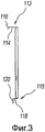
на фиг.3 показан вид сбоку слева элемента с фиг.2;figure 3 shows a side view from the left of the element of figure 2;
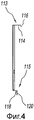
на фиг.4 показан вид справа в разрезе по линии 4 элемента с фиг.2;figure 4 shows a right side view in section along the line 4 of the element of figure 2;
на фиг.5 показан вид сверху элемента с фиг.2;figure 5 shows a top view of the element of figure 2;
на фиг.6 показан плоский вид верхнего зажима, показанного на фиг.3-5;Fig.6 shows a flat view of the upper clamp shown in Fig.3-5;
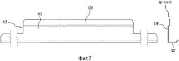
на фиг.7 показан плоский вид нижнего зажима, показанного на фиг.2-4;in Fig.7 shows a flat view of the lower clamp shown in Fig.2-4;
на фиг.8 показан вид сверху элемента с фиг.7;on Fig shows a top view of the element of Fig.7;
на фиг.9 показан плоский вид задней стенки варочной камеры кулинарной печи с фиг.1;figure 9 shows a flat view of the rear wall of the cooking chamber of the cooking furnace of figure 1;
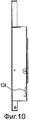
на фиг.10 показан вид в разрезе по линии 10 с фиг.9;figure 10 shows a view in section along the
на фиг.11 показан вид сбоку слева элемента с фиг.9;figure 11 shows a side view from the left of the element of figure 9;
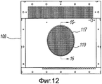
на фиг.12 показан плоский вид задней стенки варочной камеры кулинарной печи с фиг.11, со снятыми сопрягаемыми зажимами;on Fig shows a flat view of the rear wall of the cooking chamber of the cooking furnace of Fig.11, with the removed mating clamps;
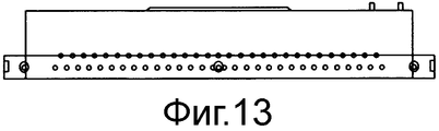
на фиг.13 показан вид сверху элемента с фиг.12;on Fig shows a top view of the element of Fig;
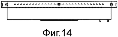
на фиг.14 показан вид снизу элемента с фиг.12;on Fig shows a bottom view of the element of Fig;
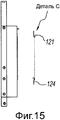
на фиг.15 показан вид сбоку элемента с фиг.12;on Fig shows a side view of the element of Fig;
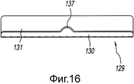
на фиг.16 показан вид спереди альтернативного верхнего зажима для съемной вентиляционной решетки кулинарной печи с фиг.1;in Fig.16 shows a front view of an alternative upper clamp for a removable ventilation grill of the cooking furnace of Fig.1;
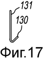
на фиг.17 показан в увеличенном масштабе вид сбоку элемента с фиг.16;on Fig shows an enlarged scale side view of the element of Fig;
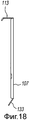
на фиг.18 показан вид сбоку альтернативного верхнего зажима для съемной вентиляционной решетки кулинарной печи с фиг.1;on Fig shows a side view of an alternative upper clamp for a removable ventilation grill culinary furnace of figure 1;
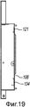
на фиг.19 показан вид сбоку задней стенки варочной камеры печи с фиг.1 с альтернативным нижним зажимом;in Fig.19 shows a side view of the rear wall of the cooking chamber of the furnace of Fig.1 with an alternative lower clamp;
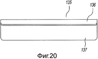
на фиг.20 показан вид спереди ручки для съемной вентиляционной решетки кулинарной печи с фиг.1;in Fig.20 shows a front view of the handle for a removable ventilation grill of the cooking furnace of Fig.1;
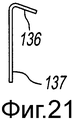
на фиг.21 показан в увеличенном масштабе вид сбоку элемента с фиг.20;on Fig shows an enlarged scale side view of the element of Fig;
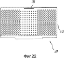
на фиг.22 показан плоский вид передней стороны съемной вентиляционной решетки кулинарной печи с фиг.1 с ручкой с фиг.20;in Fig.22 shows a flat view of the front side of the removable ventilation grill of the cooking furnace of Fig.1 with the handle of Fig.20;
на фиг.23 показан вид сбоку элемента с фиг.22.in Fig.23 shows a side view of the element of Fig.22.
Подробное описание предпочтительного варианта реализацииDetailed Description of a Preferred Embodiment
Как показано на фиг.1, кулинарная печь согласно настоящему описанию содержит увеличенную кулинарную печь 100, которая включает в себя варочную камеру 103, сообщающуюся по текучей среде с вентилятором 105 для циркулирования горячего воздуха с целью приготовления пищевого продукта (не показан), находящегося в варочной камере 103. Горячий воздух циркулирует по пути, включающем в себя варочную камеру 103, вентилятор 105, трубопровод 127 и отверстия 102 в нижней пластине, расположенной на дне варочной камеры 102 и/или отверстия 126 на верхней пластине 125, расположенной на верху варочной камеры 103. В некоторых вариантах реализации отверстия 102 и/или отверстия 103 на верхней пластине 125 могут быть соплами принудительной продувки. Воздушный поток в варочной камере 103 обозначен на фиг.1 стрелкой 106. Электрическая нагревательная спираль располагается по периферии вентилятора 105 для нагревания циркулирующего воздуха. В некоторых вариантах реализации вместо электрического нагревателя используется газовый нагреватель. Пищевая решетка 119 для размещения пищевого продукта располагается внутри и рядом со дном варочной камеры 103 в пределах воздушного потока.As shown in FIG. 1, a culinary oven according to the present description comprises an enlarged culinary furnace 100, which includes a cooking chamber 103 in fluid communication with a fan 105 for circulating hot air to prepare a food product (not shown) in the cooking chamber 103. Hot air circulates along a path including the cooking chamber 103, fan 105, conduit 127, and openings 102 in the bottom plate located at the bottom of the cooking chamber 102 and / or hole 126 on the top plate 125, located laid on top of the cooking chamber 103. In some embodiments, the openings 102 and / or openings 103 on the top plate 125 may be forced blow nozzles. The air flow in the cooking chamber 103 is indicated in FIG. 1 by arrow 106. An electric heating coil is located on the periphery of the fan 105 to heat the circulating air. In some embodiments, a gas heater is used in place of the electric heater. The food grill 119 for accommodating the food product is located inside and near the bottom of the cooking chamber 103 within the air flow.
Как показано также на фиг.8 и 11, задняя стенка 108 варочной камеры 103 содержит расположенное по центру входное отверстие для воздуха 117, выровненное с вентилятором 105, через которое циркулирующий горячий воздух втягивается вентилятором 105. Входное отверстие для воздуха содержит систему отверстий 110, через которые циркулирующий воздух поступает в направлении вентилятора 105. Отверстие для воздуха 117 может иметь любую подходящую форму. В предпочтительных вариантах реализации входное отверстие для воздуха 117 имеет круглую или овальную форму.As also shown in FIGS. 8 and 11, the
Как показано на фиг.1 и 2, съемная вентиляционная решетка 107 помещается в варочной камере 103 перед задней стенкой 108 варочной камеры 103 или между пищевым продуктом на пищевой решетке 119 и задней стенкой 108. Съемная вентиляционная решетка 107 наклонена под углом, не являющимся прямым, относительно горизонтали или вертикали. Съемная вентиляционная решетка 107 содержит перфорированный стальной лист 112 с верхним зажимом 113 и нижним зажимом 115. Перфорированный стальной лист 112 содержит по своей плоскости отверстия 109 и 111 с различным диаметром так, что пищевой продукт не подвергается возмущению высокими скоростями воздуха в то время, когда возвращающийся воздух всасывается через съемную вентиляционную решетку 107 вращающимся вентилятором 105. Размещение отверстий помогает равномерно рассеивать воздушный поток по пищевому продукту с возвращением в циркулирующий вентилятор без уменьшения общего массового расхода воздуха. Массовым расходом является скорость прохождения воздуха через систему, представленная массой за единицу времени, а не объемом за единицу времени. Съемная вентиляционная решетка 107 может сниматься так, чтобы очищать ее от жира, вытянутого из пищевого продукта и отложившегося на съемной вентиляционной решетке 107.As shown in figures 1 and 2, the
Как показано на фиг.2, типичное распределение отверстий по съемной вентиляционной решетке 107 содержит систему более мелких отверстий 111, расположенную в центре, при больших отверстиях 109, расположенных по сторонам от меньших отверстий 111. Конфигурация отверстий 109 и 111 и размеры отверстий важны для рассеивания воздуха, поскольку меньшие отверстия 111, находящиеся непосредственно перед входным отверстием для воздуха 117 на задней стенке 108, ограничивают количество воздуха, которое может пройти непосредственно через эти отверстия во входное отверстие для воздуха 117, в то время как более крупные отверстия 111 по сторонам позволяют воздуху проходить свободно для изменения пути воздушного потока, рассеивая таким образом воздушный поток. Это ведет к получению равномерного потока над пищевым продуктом, а не к сосредоточению высокоскоростного потока в середине, в направлении входного отверстия для воздуха 117. Съемная вентиляционная решетка 107 имеет такую глубину, что поперечное сечение воздушного потока поддерживается так, чтобы не нарушить расход (при данном перепаде давления).As shown in FIG. 2, a typical distribution of holes in a
Если отверстия для воздуха 111 слишком малы, возникает недостаток, заключающийся в ограничении воздушного потока, что отрицательно влияет на приготовление пищи (поджаривание пищи). Важной конфигурацией отверстий является участок, на котором помещаются более крупные отверстия 109 (с любой стороны от входного отверстия для воздуха 117) так, что воздух имеет прямой путь прохождения через вентиляционную решетку 107, и входное отверстие для воздуха 117 ограничивается так, что рассеивание воздуха становится эффективным и достаточным.If the
Съемная вентиляционная решетка 107 имеет небольшие фланцы по сторонам с целью придания жесткости этой детали. Съемная вентиляционная решетка 107 действует путем рассеивания воздуха перед его поступлением во входное отверстие для воздуха 117 (круглая конфигурация отверстий) и продолжением движения через вращающийся вентилятор 105. Конфигурация отверстий 109 и 111 и размеры отверстий важны для рассеивания воздуха, когда меньшие отверстия 111 непосредственно перед входным отверстием для воздуха 117 ограничивают количество воздуха, которое проходит напрямую через эти отверстия, в то время как более крупные отверстия 109 с любой стороны позволяют воздуху двигаться свободно по меняющемуся пути для воздуха, рассеивая таким образом воздушный поток. Съемная вентиляционная решетка 107 обладает глубиной так, что поперечное сечение воздушного потока поддерживается на уровне, при котором не оказывается отрицательного воздействия на расход потока (при данном перепаде давления).The
Как показано на фиг.1-7, верхний зажим 113 и нижний зажим 115 перфорированной пластины из нержавеющей стали 112 совмещаются с верхним зажимом 121 и нижним зажимом 123 (см. фиг.3 и 4) на задней стенке 108 варочной камеры 103. При установке съемную решетку 107 поднимают так, что верхний зажим 113 и нижний зажим 115 входят во взаимодействие с верхним зажимом 121 и нижним зажимом 123 соответственно на задней стенке 108. При удалении съемную вентиляционную решетку 107 поднимают так, что верхний зажим 113 и нижний зажим 115 отделяются от верхнего зажима 121 и нижнего зажима 123 соответственно.As shown in FIGS. 1-7, the
Верхний зажим 113 содержит первую часть 114 и вторую часть 116, которые образуют элемент в форме крюка, как показано на фиг.3, 4 и 6. Крюк ясно показан в виде детали А на фиг.6. Нижний зажим 115 содержит первую часть 118, вторую часть 120 и третью часть 122, показанные в виде детали В на фиг.7, образующей форму скобы, как показано также на фиг.3 и 4.The
Как показано на фиг.1, 9-10, 12 и 15, верхний зажим 121 задней стенки 108 имеет форму крюка, который совмещается при установке с верхним зажимом 113 съемной вентиляционной решетки 117. Нижний зажим 123 задней стенки 108 имеет форму скобы 124 (фиг.9, 10 и деталь С на фиг.15), который принимает или совмещается с третьей частью 120 нижнего зажима 115 съемной вентиляционной решетки 107.As shown in FIGS. 1, 9-10, 12, and 15, the
Угловая ориентация съемной вентиляционной решетки 107 определяется относительной шириной верхнего зажима 113 и нижнего зажима 115. Как показано на фиг.1, 3 и 4, ширина первой части верхнего зажима 113 больше ширины первой части 118 нижнего зажима 115. Это ведет к ориентации вентиляционной решетки 107 не под прямым углом, как показано на фиг.1.The angular orientation of the
Как показано на фиг.16 и 17, альтернативный вариант реализации верхнего зажима съемной вентиляционной решетки 107 представлен как верхний зажим 129, который содержит часть 131 и наклонную часть 130. Наклонная часть 130 включает в себя небольшой выступ 137, расположенный рядом с его серединой.As shown in FIGS. 16 and 17, an alternative embodiment of the upper clamp of the
Как показано на фиг.18, альтернативный вариант реализации нижнего зажима съемной вентиляционной решетки 107 содержит нижний зажим 133, обладающий наклоном для совмещения с нижним зажимом задней стенки 108.As shown in FIG. 18, an alternative embodiment of the bottom clip of the
Как показано на фиг.19, альтернативный вариант реализации нижнего зажима задней стенки 108 содержит нижний зажим 134, предназначенный для совмещения с нижним зажимом съемной вентиляционной решетки 107, например, нижний зажим 133 (фиг.18).As shown in FIG. 19, an alternative embodiment of the lower clamp of the
Как показано на фиг.20-23, ручка 135 для съемной вентиляционной решетки 107 содержит первую часть 137 и вторую наклонную часть 136. Как показано на фиг.22 и 23, ручка 235 прикреплена к верхней части съемной вентиляционной решетки 107. Например, часть 137 прикреплена к задней поверхности съемной вентиляционной решетки 107 частью 135, отходящей спереди съемной вентиляционной решетки 107 (см. фиг.23) для того, чтобы пользователь мог взяться за нее для установки или удаления съемной вентиляционной решетки 107 из варочной камеры печи 103.As shown in FIGS. 20-23, the
Кулинарная печь и способ ее использования согласно настоящему описанию включают в себя ряд ключевых, функциональных отличий от обычных вентиляционных решеток, включающих в себя: (а) съемную вентиляционную решетку, которая может быть извлечена из печи (без применения инструментов) для облегчения обслуживания или очистки, (b) угол наклона пластины не равен 90 градусам, что способствует пропуску воздушного потока из верхних сопел принудительной продувки, и (с) схему размещения отверстий, способствующую прохождению воздуха по извилистому пути до входного отверстия к циркуляционному вентилятору. Этот путь обладает увеличенной длиной при сохранении устойчивого массового расхода.A cooking stove and method of use thereof as described herein include a number of key, functional differences from conventional ventilation grills, including: (a) a removable ventilation grill that can be removed from the oven (without the use of tools) to facilitate maintenance or cleaning, (b) the angle of inclination of the plate is not equal to 90 degrees, which contributes to the passage of air flow from the upper nozzles of forced blowing, and (c) the layout of the holes to facilitate the passage of air along a winding path to the inlet to the circulation fan. This path has an increased length while maintaining a steady mass flow rate.
В то время как согласно описанию изображены один или больше вариантов реализации, следует понимать, что для специалистов в данной области техники очевидна возможность внесения многочисленных изменений. Поэтому описание не ограничивается исключительно показанными и описанными деталями, но и должно показать все изменения и модификации, которые входят в объем прилагаемой формулы изобретения.While the description depicts one or more embodiments, it should be understood that it is obvious to those skilled in the art that numerous changes can be made. Therefore, the description is not limited solely to the details shown and described, but should also show all changes and modifications that fall within the scope of the attached claims.
Claims (19)
варочную камеру для приготовления пищевого продукта, содержащую вертикальную стенку;
входное отверстие для воздуха, расположенное в середине указанной вертикальной стенки;
пластину, содержащую множество отверстий и расположенную снизу или сверху варочной камеры;
трубопровод, сообщающийся по текучей среде с указанной варочной камерой с помощью отверстий в указанной пластине и указанного входного отверстия для воздуха;
вентилятор, который осуществляет циркуляцию нагретого воздуха по указанному трубопроводу, указанной пластине, указанной варочной камере и указанному входному отверстию для воздуха для обеспечения воздушного потока внутри варочной камеры; и
вентиляционную решетку, расположенную в указанном воздушном потоке в указанной варочной камере перед указанной вертикальной стенкой и содержащую структуру, которая равномерно рассеивает указанный нагретый воздух над указанным пищевым продуктом и направляет его в указанное входное отверстие для воздуха.1. Culinary oven, which contains:
a cooking chamber for preparing a food product containing a vertical wall;
an air inlet located in the middle of said vertical wall;
a plate containing a plurality of holes and located below or above the cooking chamber;
a pipeline in fluid communication with the specified cooking chamber using the holes in the specified plate and the specified air inlet;
a fan that circulates the heated air through the specified pipe, the specified plate, the specified cooking chamber and the specified air inlet for providing air flow inside the cooking chamber; and
a ventilation grill located in said air stream in said cooking chamber in front of said vertical wall and comprising a structure that evenly disperses said heated air above said food product and directs it to said air inlet.
устанавливают пластину, имеющую множество отверстий, сверху или снизу варочной камеры кулинарной печи;
создают воздушный поток в указанной варочной камере посредством осуществления циркуляции вентилятором нагретого воздуха через трубопровод, множество отверстий пластины, указанную варочную камеру и входное отверстие для воздуха, расположенное в вертикальной стенке указанной варочной камеры; и
устанавливают указанную вентиляционную решетку в указанном воздушном потоке в указанной варочной камере перед указанной вертикальной стенкой для равномерного рассеивания нагретого воздуха по указанной варочной камере и его направления в указанное выходное отверстие для воздуха.12. A method of operating a cooking stove, according to which:
a plate having a plurality of openings is mounted above or below the cooking chamber of the cooking furnace;
creating an air flow in said cooking chamber by circulating a fan of heated air through a pipeline, a plurality of plate openings, said cooking chamber and an air inlet located in a vertical wall of said cooking chamber; and
install the specified ventilation grill in the specified air flow in the specified cooking chamber in front of the specified vertical wall for uniform dispersion of heated air through the specified cooking chamber and its direction in the specified air outlet.
удаляют указанную вентиляционную решетку из указанной варочной камеры путем подъема указанной вентиляционной решетки до тех пор, пока указанные зажимы, прикрепленные к указанной вентиляционной решетке, не выйдут из взаимодействия с указанными зажимами, прикрепленными к вертикальной стенке.14. The method according to p. 13, according to which additionally:
removing said ventilation grill from said cooking chamber by raising said ventilation grill until said clips attached to said ventilation grill come out of interaction with said clips attached to a vertical wall.
Applications Claiming Priority (4)
| Application Number | Priority Date | Filing Date | Title |
|---|---|---|---|
| US201261729105P | 2012-11-21 | 2012-11-21 | |
| US61/729,105 | 2012-11-21 | ||
| US14/074,249 US9618213B2 (en) | 2012-11-21 | 2013-11-07 | Cooking oven and method with removable air diffuser |
| US14/074,249 | 2013-11-07 |
Publications (2)
| Publication Number | Publication Date |
|---|---|
| RU2013151975A RU2013151975A (en) | 2015-05-27 |
| RU2569252C2 true RU2569252C2 (en) | 2015-11-20 |
Family
ID=49626833
Family Applications (1)
| Application Number | Title | Priority Date | Filing Date |
|---|---|---|---|
| RU2013151975/12A RU2569252C2 (en) | 2012-11-21 | 2013-11-21 | Culinary oven with removable ventilation grid and method of its use |
Country Status (4)
| Country | Link |
|---|---|
| US (1) | US9618213B2 (en) |
| EP (1) | EP2735806A1 (en) |
| CN (2) | CN204033047U (en) |
| RU (1) | RU2569252C2 (en) |
Families Citing this family (10)
| Publication number | Priority date | Publication date | Assignee | Title |
|---|---|---|---|---|
| US9618213B2 (en) * | 2012-11-21 | 2017-04-11 | Manitowoc Foodservice Companies, Llc | Cooking oven and method with removable air diffuser |
| ITTO20121075A1 (en) * | 2012-12-14 | 2014-06-15 | Indesit Co Spa | DOMESTIC COOKING OVEN |
| EP3081125A1 (en) * | 2015-04-17 | 2016-10-19 | Electrolux Appliances Aktiebolag | Cooking system |
| US9677774B2 (en) | 2015-06-08 | 2017-06-13 | Alto-Shaam, Inc. | Multi-zone oven with variable cavity sizes |
| US10088172B2 (en) | 2016-07-29 | 2018-10-02 | Alto-Shaam, Inc. | Oven using structured air |
| US10337745B2 (en) | 2015-06-08 | 2019-07-02 | Alto-Shaam, Inc. | Convection oven |
| US9879865B2 (en) | 2015-06-08 | 2018-01-30 | Alto-Shaam, Inc. | Cooking oven |
| US10890336B2 (en) | 2015-06-08 | 2021-01-12 | Alto-Shaam, Inc. | Thermal management system for multizone oven |
| CN107007162A (en) * | 2016-06-14 | 2017-08-04 | 张毅蔚 | Use air-flow oven |
| IT201700002764A1 (en) * | 2017-01-12 | 2018-07-12 | Tecnoeka S R L | FOOD BAKING OVEN |
Citations (4)
| Publication number | Priority date | Publication date | Assignee | Title |
|---|---|---|---|---|
| JPS5517023A (en) * | 1978-07-19 | 1980-02-06 | Matsushita Electric Ind Co Ltd | Hot air circulating type gas oven |
| JPS5668805U (en) * | 1979-10-31 | 1981-06-08 | ||
| JPH0393306U (en) * | 1990-01-12 | 1991-09-24 | ||
| EP1992879A1 (en) * | 2007-05-16 | 2008-11-19 | Electrolux Home Products Corporation N.V. | Cooking oven, especially domestic cooking oven |
Family Cites Families (7)
| Publication number | Priority date | Publication date | Assignee | Title |
|---|---|---|---|---|
| US4928663A (en) * | 1989-01-31 | 1990-05-29 | Bakers Pride Oven Co. | Enhanced air-flow convection oven |
| WO1995010738A1 (en) * | 1993-10-14 | 1995-04-20 | Fujimak Corporation | High speed oven |
| US6126728A (en) * | 1998-10-30 | 2000-10-03 | Agilent Technologies, Inc. | Oven air flow director |
| BRPI0309916B1 (en) | 2002-07-05 | 2018-06-12 | Turbochef Technologies, Inc. | SPEED COOKING OVEN |
| CN102113836B (en) * | 2010-01-05 | 2016-02-24 | 乐金电子(天津)电器有限公司 | Utilize the cooking device internal hot air convection system of axial-flow fan |
| CN102188168A (en) * | 2010-03-12 | 2011-09-21 | 乐金电子(天津)电器有限公司 | Baking oven with uniform large-air-volume hot air convection barbecuing function |
| US9618213B2 (en) * | 2012-11-21 | 2017-04-11 | Manitowoc Foodservice Companies, Llc | Cooking oven and method with removable air diffuser |
-
2013
- 2013-11-07 US US14/074,249 patent/US9618213B2/en not_active Expired - Fee Related
- 2013-11-20 EP EP13193705.4A patent/EP2735806A1/en not_active Withdrawn
- 2013-11-21 RU RU2013151975/12A patent/RU2569252C2/en not_active IP Right Cessation
- 2013-11-21 CN CN201320745897.1U patent/CN204033047U/en not_active Withdrawn - After Issue
- 2013-11-21 CN CN201310596175.9A patent/CN103829776B/en not_active Expired - Fee Related
Patent Citations (4)
| Publication number | Priority date | Publication date | Assignee | Title |
|---|---|---|---|---|
| JPS5517023A (en) * | 1978-07-19 | 1980-02-06 | Matsushita Electric Ind Co Ltd | Hot air circulating type gas oven |
| JPS5668805U (en) * | 1979-10-31 | 1981-06-08 | ||
| JPH0393306U (en) * | 1990-01-12 | 1991-09-24 | ||
| EP1992879A1 (en) * | 2007-05-16 | 2008-11-19 | Electrolux Home Products Corporation N.V. | Cooking oven, especially domestic cooking oven |
Also Published As
| Publication number | Publication date |
|---|---|
| EP2735806A1 (en) | 2014-05-28 |
| US20140137852A1 (en) | 2014-05-22 |
| CN103829776B (en) | 2017-04-12 |
| CN103829776A (en) | 2014-06-04 |
| RU2013151975A (en) | 2015-05-27 |
| CN204033047U (en) | 2014-12-24 |
| US9618213B2 (en) | 2017-04-11 |
Similar Documents
| Publication | Publication Date | Title |
|---|---|---|
| RU2569252C2 (en) | Culinary oven with removable ventilation grid and method of its use | |
| JP6211659B2 (en) | Apparatus for cooking food and air guide member therefor | |
| US3943836A (en) | Apparatus for removing fumes from the space above a cooking appliance in a restaurant | |
| US10371391B2 (en) | Cooking oven provided for heat transfer by convection | |
| CN107920687A (en) | Convection oven | |
| EP0217802B1 (en) | Air exhausting means | |
| CN107923630A (en) | With the modular appliance for cooking region and fume extractor | |
| RU2007111953A (en) | OVEN | |
| CN107923631A (en) | With the modular appliance for cooking region and fume extractor | |
| US6904903B1 (en) | Convection steamer with forced recirculation through steam bath | |
| KR20060108796A (en) | Convection oven range having multi-duct | |
| US8437627B1 (en) | Apparatus for extending the holding time for food | |
| KR20180053857A (en) | A Kitchen Hood Integrated Cooktop | |
| CN109419317A (en) | Cooking utensil | |
| WO2020202012A1 (en) | Extractor unit | |
| US6394083B1 (en) | Adjustable ventilator cartridge filter | |
| CN109028185B (en) | Fume exhaust fan | |
| CN110121620A (en) | Heating device, air exchange system and method for exhausting | |
| CN208740738U (en) | Baffle arrangement and equipment is scorched including it | |
| CN208606244U (en) | Kitchen ventilator positive pressure dust-precipitating system | |
| JPH10216025A (en) | Hot plate | |
| JPWO2019053793A1 (en) | Cooker | |
| CN217429810U (en) | Baking cooking equipment | |
| CN216256737U (en) | Filter and cooking device | |
| CN219249908U (en) | Novel accuse Wen Kaolu |
Legal Events
| Date | Code | Title | Description |
|---|---|---|---|
| MM4A | The patent is invalid due to non-payment of fees |
Effective date: 20201122 |