RU2568373C2 - Diagnostics of fuel injectors - Google Patents
Diagnostics of fuel injectors Download PDFInfo
- Publication number
- RU2568373C2 RU2568373C2 RU2011147111/06A RU2011147111A RU2568373C2 RU 2568373 C2 RU2568373 C2 RU 2568373C2 RU 2011147111/06 A RU2011147111/06 A RU 2011147111/06A RU 2011147111 A RU2011147111 A RU 2011147111A RU 2568373 C2 RU2568373 C2 RU 2568373C2
- Authority
- RU
- Russia
- Prior art keywords
- fuel
- cylinder
- fuel injection
- amount
- injected
- Prior art date
Links
Images

Classifications
-
- F—MECHANICAL ENGINEERING; LIGHTING; HEATING; WEAPONS; BLASTING
- F02—COMBUSTION ENGINES; HOT-GAS OR COMBUSTION-PRODUCT ENGINE PLANTS
- F02D—CONTROLLING COMBUSTION ENGINES
- F02D41/00—Electrical control of supply of combustible mixture or its constituents
- F02D41/008—Controlling each cylinder individually
- F02D41/0085—Balancing of cylinder outputs, e.g. speed, torque or air-fuel ratio
-
- F—MECHANICAL ENGINEERING; LIGHTING; HEATING; WEAPONS; BLASTING
- F02—COMBUSTION ENGINES; HOT-GAS OR COMBUSTION-PRODUCT ENGINE PLANTS
- F02D—CONTROLLING COMBUSTION ENGINES
- F02D41/00—Electrical control of supply of combustible mixture or its constituents
- F02D41/22—Safety or indicating devices for abnormal conditions
-
- F—MECHANICAL ENGINEERING; LIGHTING; HEATING; WEAPONS; BLASTING
- F02—COMBUSTION ENGINES; HOT-GAS OR COMBUSTION-PRODUCT ENGINE PLANTS
- F02D—CONTROLLING COMBUSTION ENGINES
- F02D41/00—Electrical control of supply of combustible mixture or its constituents
- F02D41/30—Controlling fuel injection
- F02D41/38—Controlling fuel injection of the high pressure type
- F02D41/40—Controlling fuel injection of the high pressure type with means for controlling injection timing or duration
- F02D41/401—Controlling injection timing
-
- G—PHYSICS
- G01—MEASURING; TESTING
- G01M—TESTING STATIC OR DYNAMIC BALANCE OF MACHINES OR STRUCTURES; TESTING OF STRUCTURES OR APPARATUS, NOT OTHERWISE PROVIDED FOR
- G01M15/00—Testing of engines
-
- G—PHYSICS
- G01—MEASURING; TESTING
- G01M—TESTING STATIC OR DYNAMIC BALANCE OF MACHINES OR STRUCTURES; TESTING OF STRUCTURES OR APPARATUS, NOT OTHERWISE PROVIDED FOR
- G01M15/00—Testing of engines
- G01M15/04—Testing internal-combustion engines
-
- Y—GENERAL TAGGING OF NEW TECHNOLOGICAL DEVELOPMENTS; GENERAL TAGGING OF CROSS-SECTIONAL TECHNOLOGIES SPANNING OVER SEVERAL SECTIONS OF THE IPC; TECHNICAL SUBJECTS COVERED BY FORMER USPC CROSS-REFERENCE ART COLLECTIONS [XRACs] AND DIGESTS
- Y02—TECHNOLOGIES OR APPLICATIONS FOR MITIGATION OR ADAPTATION AGAINST CLIMATE CHANGE
- Y02T—CLIMATE CHANGE MITIGATION TECHNOLOGIES RELATED TO TRANSPORTATION
- Y02T10/00—Road transport of goods or passengers
- Y02T10/10—Internal combustion engine [ICE] based vehicles
- Y02T10/40—Engine management systems
Landscapes
- Engineering & Computer Science (AREA)
- Chemical & Material Sciences (AREA)
- Combustion & Propulsion (AREA)
- Mechanical Engineering (AREA)
- General Engineering & Computer Science (AREA)
- Physics & Mathematics (AREA)
- General Physics & Mathematics (AREA)
- Electrical Control Of Air Or Fuel Supplied To Internal-Combustion Engine (AREA)
- Combined Controls Of Internal Combustion Engines (AREA)
Abstract
Description
Область техники, к которой относится изобретениеFIELD OF THE INVENTION
Настоящее изобретение относится к способу диагностики топливных форсунок.The present invention relates to a method for diagnosing fuel injectors.
Уровень техникиState of the art
Контроллеры двигателя и стратегии регулирования двигателя обеспечивают функционирование топливных форсунок для подачи точного количества топлива в определенные отрезки времени относительно угла поворота коленвала двигателя для увеличения КПД двигателя и сокращения выбросов двигателя. Кроме того, когда точное количество топлива впрыскивается под точным углом поворота коленвала двигателя, может быть получена ожидаемая величина крутящего момента коленвала двигателя в цилиндре двигателя. Однако если уменьшается эффективность топливной форсунки или другого элемента системы впрыска топлива, существует возможность уменьшения эффективности крутящего момента двигателя и выбросов во время работы двигателя. Например, изменение времени реакции форсунки может влиять на момент впрыска топлива таким образом, что крутящая сила двигателя изменится, а качество автомобильных выбросов снизится.Engine controllers and engine control strategies enable fuel injectors to deliver the exact amount of fuel at specific times relative to the angle of rotation of the engine crankshaft to increase engine efficiency and reduce engine emissions. In addition, when the exact amount of fuel is injected at the exact angle of rotation of the engine crankshaft, the expected magnitude of the engine crankshaft torque in the engine cylinder can be obtained. However, if the efficiency of the fuel injector or other element of the fuel injection system decreases, there is the possibility of decreasing the efficiency of engine torque and emissions during engine operation. For example, a change in the reaction time of the nozzle can affect the moment of fuel injection in such a way that the engine torque will change and the quality of automobile emissions will decrease.
В патенте США №7,317,983 авторы описывают способ регулирования крутящего момента цилиндра в зависимости от частоты вращения двигателя. В частности, в соответствии с этим способом впрыскиваемое в цилиндр количество топлива регулируется на основании частоты вращения двигателя, которая относится к конкретной системе впрыска и сгорания топлива. Однако в соответствии с этим способом делаются поправки на дисбаланс крутящих моментов, но не проводится диагностика работы форсунки. Например, в соответствии с этим способом регулируется количество топлива, впрыскиваемое в цилиндр, для исправления дисбаланса крутящих моментов, но этот способ не определяет, работает ли топливная форсунка в соответствии с прогнозируемыми рабочими характеристиками. Также этот способ не проводит диагностику того, относятся ли ошибки системы впрыска к изменениям количества впрыскиваемого топлива или к изменениям начала и окончания впрыска топлива.In US patent No. 7,317,983, the authors describe a method for controlling the torque of a cylinder depending on the engine speed. In particular, in accordance with this method, the amount of fuel injected into the cylinder is controlled based on the engine speed, which relates to a particular fuel injection and combustion system. However, in accordance with this method, corrections are made for the imbalance of torques, but the nozzle is not diagnosed. For example, in accordance with this method, the amount of fuel injected into the cylinder is adjusted to correct the imbalance of the torques, but this method does not determine if the fuel injector is operating in accordance with the predicted performance. Also, this method does not diagnose whether the errors in the injection system relate to changes in the amount of fuel injected or to changes in the start and end of the fuel injection.
Раскрытие изобретенияDisclosure of invention
Авторы настоящего патента учли вышеуказанные недостатки и разработали способ диагностирования системы впрыска топлива, включающий в себя: регулировку количества топлива, впрыскиваемого в цилиндр для уравновешивания крутящих моментов, производимых цилиндром, с крутящими моментами, производимыми другим цилиндром; развертку синхронизации впрыска топлива в цилиндр во время регулировки количества впрыскиваемого топлива; обозначение уменьшения эффективности системы впрыска топлива, когда минимальное количество топлива, впрыскиваемое в цилиндр, для уравновешивания крутящих моментов, произведенных в цилиндре, выходит за пределы рабочего диапазона.The authors of this patent took into account the above disadvantages and developed a method for diagnosing a fuel injection system, which includes: adjusting the amount of fuel injected into the cylinder to balance the torques produced by the cylinder with the torques produced by the other cylinder; sweep synchronization of fuel injection into the cylinder during adjustment of the amount of injected fuel; designation of a decrease in the efficiency of the fuel injection system when the minimum amount of fuel injected into the cylinder to balance the torques produced in the cylinder is outside the operating range.
Регулируя количество топлива и синхронизацию впрыска топлива, можно определить, впрыскивает ли топливная форсунка предполагаемое количество топлива в предполагаемый период времени. Например, развертка количества впрыскиваемого топлива и синхронизация впрыска топлива могут предоставить информацию для определения того, балансирует ли минимальное количество впрыскиваемого топлива крутящие моменты цилиндра. Минимальное количество топлива, которое балансирует крутящие моменты цилиндра, и синхронизацию, которая происходит, когда минимальное количество топлива балансирует крутящие моменты цилиндра, можно сравнить с ранее определенной синхронизацией и минимальным количеством впрыскиваемого топлива, необходимым для равновесия крутящих моментов цилиндра. Если минимальное количество топлива, необходимое для уравновешивания крутящих моментов цилиндра двигателя, определенное в настоящий момент, выходит за пределы рабочих характеристик, можно определить уменьшение эффективности работы форсунки. Таким образом, равновесие крутящих моментов и минимальное количество впрыскиваемого топлива для равновесия крутящих моментов цилиндра можно использовать для диагностики работы топливной форсунки.By adjusting the amount of fuel and the timing of the fuel injection, it can be determined whether the fuel injector injects the estimated amount of fuel in the estimated time period. For example, a sweep of the amount of fuel injected and timing of the fuel injection can provide information to determine if the minimum amount of fuel injected balances the cylinder torques. The minimum amount of fuel that balances the cylinder torques and the timing that occurs when the minimum amount of fuel balances the cylinder torques can be compared with the previously determined timing and the minimum amount of fuel injected needed to balance the torques of the cylinder. If the minimum amount of fuel needed to balance the engine cylinder torques that is currently determined is outside the performance range, you can determine the decrease in nozzle performance. Thus, the balance of torques and the minimum amount of fuel injected to balance the torques of the cylinder can be used to diagnose the operation of the fuel injector.
Настоящее описание имеет несколько преимуществ. Например, во-первых, этот подход может предоставить определенную информацию, касающуюся уменьшения эффективности работы топливной форсунки. Во-вторых, при помощи этого подхода можно точно определить, связано ли уменьшение эффективности работы форсунки с количеством впрыскиваемого топлива или с синхронизацией начала и окончания впрыска топлива. В-третьих, этот подход можно использовать без дополнительных диагностических аппаратных средств. В-четвертых, этот подход можно использовать, если двигатель работает в нормальных условиях.The present description has several advantages. For example, firstly, this approach can provide certain information regarding the decrease in the efficiency of the fuel injector. Secondly, using this approach, you can accurately determine whether the decrease in the efficiency of the nozzle is associated with the amount of injected fuel or with the synchronization of the beginning and end of fuel injection. Thirdly, this approach can be used without additional diagnostic hardware. Fourth, this approach can be used if the engine is operating under normal conditions.
Вышеуказанные преимущества и другие преимущества и характеристики настоящего изобретения представлены в разделе "Осуществление изобретения" отдельно или с иллюстрацией на прилагаемых чертежах.The above advantages and other advantages and characteristics of the present invention are presented in the section "Implementation of the invention" separately or with illustration in the accompanying drawings.
Необходимо понимать, что раскрытие изобретения, предоставленное выше, представлено для иллюстрации набора вариантов осуществления изобретения в упрощенной форме, которые развернуто представлены в разделе "Осуществление изобретения". Представленное описание изобретения не предназначено для определения ключевых и важных характеристик заявленного объекта, объем охраны которого определяется исключительно формулой изобретения, которая следует за разделомYou must understand that the disclosure of the invention provided above is presented to illustrate the set of embodiments of the invention in a simplified form, which are expanded presented in the section "Implementation of the invention". The presented description of the invention is not intended to determine the key and important characteristics of the claimed object, the scope of protection of which is determined solely by the claims, which follows the section
"Осуществление изобретения"."Implementation of the invention."
Кроме того, заявленный объект не ограничивается вариантами осуществления изобретения, которые устраняют недостатки, описанные выше или в любой части настоящего раскрытия изобретения.In addition, the claimed subject matter is not limited to embodiments of the invention that eliminate the disadvantages described above or in any part of the present disclosure.
Краткое описание чертежейBrief Description of the Drawings
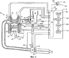
На Фиг.1 показано схематическое изображение двигателя;Figure 1 shows a schematic illustration of an engine;
На Фиг.2-4 показано прогнозируемое соотношение между количеством впрыскиваемого топлива, синхронизацией впрыска топлива и равновесием крутящих моментов цилиндра;Figure 2-4 shows the predicted relationship between the amount of fuel injected, the timing of the fuel injection and the balance of torque of the cylinder;
На Фиг.5 показана блок-схема способа диагностирования работы топливной форсунки.Figure 5 shows a block diagram of a method for diagnosing the operation of a fuel injector.
Осуществление изобретенияThe implementation of the invention
Настоящее описание относится к контролю впрыска топлива двигателя. На Фиг.1 показан пример форсированного двигателя с прямым впрыском топлива. На Фиг.5 показан способ регулировки синхронизации впрыска топлива и количества впрыскиваемого топлива для диагностики работы топливной форсунки. На Фиг.2-4 показано соотношение между минимальным количеством впрыскиваемого топлива, синхронизацией впрыска топлива и равновесием крутящих моментов цилиндра.The present description relates to the control of engine fuel injection. Figure 1 shows an example of a forced engine with direct fuel injection. Figure 5 shows a method for adjusting the timing of fuel injection and the amount of fuel injected to diagnose the operation of the fuel injector. Figure 2-4 shows the relationship between the minimum amount of injected fuel, the timing of the fuel injection and the balance of torque of the cylinder.
Как показано на Фиг.1, управление двигателем 10 внутреннего сгорания, содержащим несколько цилиндров, один из которых показан на Фиг.1, осуществляется при помощи электронного контроллера 12 двигателя. Двигатель 10 содержит камеру 30 сгорания и стенки 32 цилиндра с расположенным в цилиндре поршнем 36, соединенным с коленвалом 40. Камера 30 сгорания показана соединенной с впускным коллектором 44 и выпускным коллектором 48 через соответствующий впускной клапан 52 и выпускной клапан 54. Управление впускным и выпускным клапанами может быть осуществлено при помощи впускного кулачка 51 и выпускного кулачка 53. Положение впускного кулачка 51 может быть определено датчиком 55 впускного кулачка. Положение выпускного кулачка 53 может быть определено датчиком 57 выпускного кулачка.As shown in FIG. 1, the control of an
Топливная форсунка 66 расположена с возможностью впрыскивания топлива непосредственно в цилиндр 30, что известно специалистам в данной области техники как прямой впрыск. Топливная форсунка 66 подает жидкое топливо пропорционально ширине импульса сигнала FPW (волны давления топлива) от контроллера 12. Топливо подают в топливную форсунку 66 системой подачи топлива (не показана), содержащей топливный бак, топливный насос, направляющую-распределитель для топлива (не показаны). Давление топлива, подаваемого системой подачи топлива, может быть отрегулировано путем изменения положения позиционного клапана, регулирующего поток в топливный насос (не показан). Кроме того, дозирующий клапан может быть расположен в направляющей - распределителе для топлива или рядом с ней для регулирования подачи топлива с обратной связью. Питание топливной форсунки 66 осуществляют током от привода 68, который реагирует на сигнал контроллера 12.The
Впускной коллектор 44 соединен с дополнительной дроссельной заслонкой 62 с электроприводом, которая регулирует положение дроссельной заслонки 64 для контроля притока воздуха из заборной камеры 46 наддува. Компрессор 162 забирает воздух из воздухозаборника 42 и для его доставки в камеру 46 наддува. Турбина 164 для закручивания выхлопных газов механически соединена с компрессором 162.The
Сгорание начинается в камере 30 сгорания, когда топливо автоматически воспламеняется при приближении поршня к верхней мертвой точке такта сжатия. В некоторых вариантах осуществления настоящего изобретения универсальный датчик содержания кислорода в выхлопных газах (датчик UEGO) (не показан) может быть соединен с выпускным коллектором 48, который находится выше по потоку, чем устройство 70 для снижения токсичности выхлопа. В других вариантах осуществления настоящего изобретения датчик UEGO может быть расположен ниже по потоку, чем одно или более устройств для предварительной очистки выхлопных газов. Кроме того, в некоторых вариантах осуществления настоящего изобретения датчик UEGO может быть заменен датчиком окислов азота.Combustion begins in the
Устройство 70 для снижения токсичности выхлопа может содержать сажевый фильтр и блоки каталитического нейтрализатора в одном варианте воплощения изобретения. В другом варианте воплощения изобретения может могут быть использованы несколько устройств для снижения токсичности выхлопа с отдельными блоками. Устройство 70 для снижения токсичности выхлопа может содержать катализатор окисления. В других вариантах воплощения изобретения устройство для снижения токсичности выхлопа может содержать абсорбер окислов азота или систему SCR снижения токсичности выхлопа.An
Контроллер 12, показанный на Фиг.1, как обычный микрокомпьютер, содержит блок 102 микропроцессора, порты 104 входа/выхода, ПЗУ 106, ОЗУ 108, оперативную энергонезависимую память 110 и традиционную шину данных. Контроллер 12 получает различные сигналы от датчиков, соединенных с двигателем 10, которые, кроме описанных выше, включают в себя температуру двигателя от датчика 112 температуры, соединенного с рукавом 114 охлаждения; позиционный датчик 134, соединенный с педалью 130 газа для определения положения педали газа, которое регулируют ногой 132 водителя; сигнал от датчика 80 давления для определения давления на выходе выше турбины 164; сигнал от датчика 82 давления для определения давления выхлопных газов ниже по потоку турбины 164; результаты измерения давления впускного коллектора (MAP) от датчика 122 давления, соединенного с впускным коллектором 44; сигнал от датчика контроля положения двигателя от 118 датчика холла, контролирующего положение коленвала 40; результат измерения датчиком 120 количества воздуха, поступающего в двигатель (например, от термоанемометра); результаты измерения датчиком 58 положения дроссельной заслонки. Барометрическое давление также может быть измерено (датчик не показан) для обработки контроллером 12. В предпочтительном варианте осуществления настоящего изобретения датчик 118 контроля положения двигателя производит предопределенное количество равномерно распределенных импульсов во время каждого поворота коленвала, при помощи чего может быть определена частота оборотов двигателя (об/мин).The
В некоторых вариантах воплощения изобретения двигатель может быть соединен с системой электродвигателей/аккумуляторов в автомобиле с гибридным приводом. Автомобиль с гибридным приводом может иметь схемы параллельного соединения, схемы последовательного соединения или их сочетание.In some embodiments of the invention, the engine may be coupled to an electric motor / battery system in a hybrid vehicle. A hybrid vehicle may have parallel circuitry, serial circuitry, or a combination thereof.
Во время работы каждый цилиндр двигателя 10 проходит четырехтактный цикл: такт впуска, такт сжатия, такт расширения и такт выпуска. Во время такта впуска, как правило, закрывается выпускной клапан 54 и открывается впускной клапан 52. Воздух поступает в камеру 30 сгорания через впускной коллектор 44, и поршень 36 перемещается к дну цилиндра для увеличения объема камеры 30 сгорания. Положение, в котором поршень 36 достигает дна цилиндра и находится в конце такта (т.е. когда камера 30 сгорания имеет наибольший объем), обычно называется специалистами в данной области техники нижней мертвой точкой. Во время такта сжатия впускной клапан 52 и выпускной клапан 54 закрыты. Поршень 36 двигается по направлению к головке блока цилиндров для сжатия воздуха в камере сгорания 30. Точка, в которой поршень 36 находится в конце такта и максимально близко к головке цилиндров (т.е. когда камера 30 сгорания имеет наименьший объем), обычно называется специалистами в данной области техники верхней мертвой точкой. В процессе, который в дальнейшем называется впрыск, топливо подается в камеру сгорания. В некоторых вариантах воплощения изобретения топливо может впрыскиваться в цилиндр несколько раз во время одного цикла работы цилиндра. В процессе, который в дальнейшем называется зажигание, впрыскиваемое топливо воспламеняется от сжатия или от известных средств зажигания, например свечи зажигания (не показаны), что приводит к возгоранию. Во время такта расширения дросселируемый газ направляет поршень 36 в НМТ. Коленвал 40 преобразует движение поршня в крутящий момент вращающегося вала. Во время такта выпуска выпускной клапан 54 открывается и выпускает воспламененную топливно-воздушную смесь из выпускного коллектора 48, а поршень возвращается в ВМТ. Описанная выше реализация является только примером осуществления настоящего изобретения и время открытия и/или закрытия впускного и выпускного клапанов могут отличаться для обеспечения положительного или отрицательного перекрытия клапанов, запаздывания закрытия впускного клапана и др. В некоторых вариантах воплощения изобретения может быть также использован 2-тактный цикл, а не 4-тактный.During operation, each cylinder of the
Таким образом, система на Фиг.1 представляет собой систему диагностики работы топливной форсунки, содержащую двигатель, топливную форсунку, находящуюся в гидравлическом соединении с цилиндром двигателя и контроллер, при этом контроллер содержит команды регулировки количества топлива, впрыскиваемого в цилиндр для равновесия крутящих моментов в цилиндре, для обеспечения синхронизации впрыска топлива цилиндра во время регулирования количества впрыскиваемого топлива, для задания условий снижения синхронизации начала и конца впрыска топлива и для задания условий снижения количества топлива, впрыскиваемого в цилиндр в ответ на минимальное количество топлива, впрыскиваемого в цилиндр для равновесия крутящих моментов в цилиндре, которые находятся за пределами рабочего диапазона. Вариантом осуществления изобретения является система с прямым впрыском и дизельным двигателем. В одном варианте осуществления изобретения система содержит контроллер, содержащий дополнительные команды для регулировки равновесия крутящих моментов каждого из множества цилиндров двигателя. В одном варианте осуществления изобретения система содержит контроллер, содержащий команды регулировки количества впрыскиваемого топлива или начало синхронизации впрыска топлива, которые находятся за пределами количества впрыскиваемого топлива и начала синхронизации впрыска топлива, когда отсутствует равновесие крутящих моментов цилиндра.Thus, the system of FIG. 1 is a fuel injector diagnostic system comprising an engine, a fuel injector in fluid communication with an engine cylinder and a controller, the controller comprising instructions for adjusting the amount of fuel injected into the cylinder to balance the torques in the cylinder , to ensure synchronization of the fuel injection of the cylinder during regulation of the amount of injected fuel, to set the conditions for reducing the synchronization of the beginning and end of the injection, Lebanon, and to set the conditions for reducing the amount of fuel injected into the cylinder in response to the minimum quantity of fuel injected into the cylinder to balance the torques in the cylinder, which are outside the operating range. An embodiment of the invention is a direct injection system and a diesel engine. In one embodiment of the invention, the system comprises a controller comprising additional instructions for adjusting the balance of torques of each of the plurality of engine cylinders. In one embodiment of the invention, the system comprises a controller comprising instructions for adjusting the amount of fuel injected or starting a fuel injection timing that are outside the amount of fuel injected and starting fuel injection timing when the cylinder torque is not balanced.
В некоторых двигателях (например, дизельных) количество крутящих моментов, производимых цилиндром посредством коленвала двигателя, может быть связано с синхронизацией впрыска топлива, а также с количеством впрыскиваемого топлива. Например, если количество топлива впрыскивается в цилиндр, начиная с угла поворота коленвала 140 градусов до ВМТ такта сжатия цилиндра, а синхронизация впрыска топлива имеет постоянное значение, крутящий момент, производимый цилиндром, может быть отрегулирован, по меньшей мере, до некоторой степени, путем регулирования количества топлива, впрыскиваемого в цилиндр. Добавление топлива может увеличить количество химической энергии в цилиндре, в то время как снижение топлива в цилиндре может снизить количество химической энергии в цилиндре. С другой стороны, синхронизация впрыска топлива воспламенения от сжатия может повлиять на опережение зажигания, таким образом, оказывая влияние на количество крутящих моментов, производимых цилиндром, по меньшей мере, в некоторых условиях. В частности, синхронизация впрыска топлива может повлиять на возникновение крутящих моментов при помощи изменения времени выделения теплоты цилиндра. Кроме того, время выделения теплоты цилиндра может повлиять на выхлопы двигателя, так как время выделения теплоты влияет на выхлопы двигателя, например окислы азота. В соответствии с этим существует необходимость определить, влияет ли количество впрыскиваемого топлива и/или синхронизация впрыска топлива на работу цилиндра.In some engines (e.g. diesel), the number of torques produced by the cylinder through the engine crankshaft may be related to the timing of the fuel injection, as well as to the amount of fuel injected. For example, if the amount of fuel is injected into the cylinder, starting from a crankshaft rotation angle of 140 degrees to the TDC of the cylinder compression stroke, and the fuel injection timing is constant, the torque produced by the cylinder can be adjusted at least to some extent by adjusting the amount of fuel injected into the cylinder. Adding fuel can increase the amount of chemical energy in the cylinder, while lowering the fuel in the cylinder can reduce the amount of chemical energy in the cylinder. On the other hand, the timing of compression ignition fuel injection can affect the timing of the ignition, thus affecting the number of torques produced by the cylinder, at least in some conditions. In particular, synchronization of fuel injection can affect the occurrence of torques by changing the time the cylinder generates heat. In addition, the heat release time of the cylinder can affect the exhaust of the engine, since the heat release time affects the exhaust of the engine, for example nitrogen oxides. Accordingly, there is a need to determine whether the amount of fuel injected and / or the timing of the fuel injection affects the operation of the cylinder.
На Фиг.2-4 показано визуальное представление характеристик впрыска топлива, которые используются в способе, показанном на Фиг.5, для того, чтобы определить, влияет ли синхронизация впрыска топлива по отношению к положению коленвала или количество впрыскиваемого топлива на крутящий момент цилиндра и равновесие крутящих моментов цилиндра. В частности, на Фиг.2-4 показано отношение между количеством впрыскиваемого топлива, синхронизацией впрыска топлива относительно положения угла коленвала и равновесием крутящего момента цилиндра.Figure 2-4 shows a visual representation of the fuel injection characteristics that are used in the method shown in Figure 5, in order to determine whether the timing of the fuel injection relative to the position of the crankshaft or the amount of fuel injected affects the cylinder torque and balance cylinder torques. In particular, FIGS. 2-4 show the relationship between the amount of fuel injected, the timing of the fuel injection relative to the position of the crankshaft angle, and the balance of the torque of the cylinder.
На Фиг.2 показан прогнозируемый график крутящих моментов цилиндра, уравновешивающий регулировку количества топлива по отношению к синхронизации впрыска топлива. По оси Y показана коррекция количества топлива, используемая для уравновешивания крутящих моментов, производимых цилиндром, с крутящими моментами, производимыми другими цилиндрами. В альтернативном варианте осуществления настоящего изобретения по оси Y может быть показана коррекция количества топлива, используемая для уравновешивания крутящих моментов, произведенных цилиндром, с прогнозируемым количеством крутящих моментов, производимых цилиндром во время базовых рабочих условий (т.е. синхронизация впрыска топлива и количество топлива, которые производят крутящий момент двигателя, ускоряющий работу двигателя известным образом). Например, ноль на оси Y соответствует базовому количеству топлива для выбранных условий работы двигателя, а значение 4 означает базовое количество топлива плюс 4 мг/такт дополнительного топлива.Figure 2 shows a predicted graph of cylinder torques balancing the adjustment of the amount of fuel relative to the timing of the fuel injection. The Y axis shows the amount of fuel correction used to balance the torques produced by the cylinder with the torques produced by the other cylinders. In an alternative embodiment of the present invention, the fuel axis correction used to balance the torques produced by the cylinder with the predicted number of torques produced by the cylinder during basic operating conditions (i.e., fuel injection timing and fuel quantity, which produce engine torque, accelerating the engine in a known manner). For example, a zero on the Y axis corresponds to the base amount of fuel for the selected engine operating conditions, and a value of 4 means the base amount of fuel plus 4 mg / cycle of additional fuel.
По оси Х показано начало положения синхронизации впрыска топлива по отношению к положению коленвала двигателя. В альтернативных вариантах осуществления изобретения по оси Х может быть показан конец синхронизации впрыска топлива по отношению к положению коленвала двигателя. В настоящем варианте осуществления изобретения ноль относится к базовому старту синхронизации впрыска топлива для выбранных условий работы двигателя. Например, при скорости холостого хода 700 оборотов в минуту базовый старт синхронизации впрыска топлива может составлять угол положения коленвала 160 градусов до ВМТ такта сжатия. Таким образом, в соответствии с диаграммой на Фиг.2 значение ноль соответствует углу положения коленвала 160 градусов до ВМТ такта сжатия. Значение -20 соответствует углу положения коленвала 140 градусов до ВМТ такта сжатия, а значение 20 соответствует углу положения коленвала 180 градусов до ВМТ такта сжатия. В других вариантах осуществления ноль может соответствовать положению ВМТ такта сжатия. Однако соотношение между количеством топлива и синхронизацией впрыска топлива сохраняется. Таким образом, единицы и/или числовые значения, показанные на Фиг.2, могут быть изменены без выхода за границы объема настоящего изобретения.The X axis shows the start of the fuel injection timing position with respect to the position of the engine crankshaft. In alternative embodiments, the end of the fuel injection synchronization with respect to the position of the engine crankshaft may be shown along the X axis. In the present embodiment, zero refers to the base start of the fuel injection timing for the selected engine operating conditions. For example, at an idle speed of 700 revolutions per minute, the basic start of synchronization of fuel injection can be an angle of crankshaft position of 160 degrees to TDC compression stroke. Thus, in accordance with the diagram in figure 2, the value zero corresponds to the angle of the crankshaft position of 160 degrees to TDC compression stroke. A value of -20 corresponds to a crankshaft position angle of 140 degrees to TDC compression stroke, and a value of 20 corresponds to a crankshaft position angle of 180 degrees to TDC compression stroke. In other embodiments, the implementation of zero may correspond to the position of the TDC compression cycle. However, the relationship between fuel quantity and fuel injection timing is maintained. Thus, the units and / or numerical values shown in FIG. 2 can be changed without departing from the scope of the present invention.
Каждая вертикальная линия 202 соответствует регулировке количества топлива относительно базового количества топлива и регулировке синхронизации впрыска топлива, которые уравновешивают крутящие моменты, производимые цилиндром, в который впрыскивается топливо, для топливной форсунки, которая впрыскивает необходимое количество топлива. Таким образом, на Фиг.2 показано, что минимальное количество топлива, необходимое для уравновешивания крутящих моментов цилиндра, составляет -10 градусов по отношению к базовой синхронизации впрыска топлива. Кроме того, минимальное количество топлива, необходимое для уравновешивания цилиндра, - это базовое количество топлива минус около 2 мг/такт. На Фиг.2 показано, что количество топлива, впрыскиваемого в цилиндр для уравновешивания крутящего момента цилиндра, увеличивается для синхронизации впрыска топлива до или после положения коленвала -10 градусов. Также можно увидеть, что количество топлива, впрыскиваемое для уравновешивания крутящих моментов цилиндра, увеличивается при большей скорости, когда синхронизация впрыска топлива замедляется, а не ускоряется с положения -10 градусов. Таким образом, для увеличения экономии топлива целесообразно замедлить синхронизацию впрыска топлива на 10 градусов. Однако, как указано выше, синхронизация впрыска топлива может повлиять на выхлопы двигателя, поэтому может быть целесообразно установить синхронизацию впрыска топлива на угол положения коленвала, отличающийся от -10 градусов для условий вождения.Each
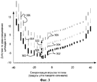
На Фиг.3 показан прогнозируемый график крутящих моментов цилиндра, балансирующий регулировку количества топлива по отношению к синхронизации впрыска топлива при трех разных условиях впрыска топлива. Оси Х и Y такие же, как показано на Фиг.2. Таким образом, описание осей Х и Y опускается для краткости.Figure 3 shows a predicted graph of cylinder torques balancing the adjustment of the amount of fuel relative to the timing of the fuel injection under three different fuel injection conditions. Axes X and Y are the same as shown in FIG. 2. Thus, the description of the X and Y axes is omitted for brevity.
Каждая узкая вертикальная линия 306 соответствует регулировке количества топлива по отношению к базовому количеству топлива и регулировке синхронизации впрыска топлива, которые уравновешивают крутящие моменты, производимые цилиндром, в который впрыскивается топливо, для форсунки, которая впрыскивает меньше топлива, чем необходимо. Все вертикальные линии 306 представляют развертку количества впрыскиваемого топлива и синхронизации впрыска топлива для получения уравновешенных крутящих моментов в цилиндре. Например, количество впрыскиваемого топлива и начало синхронизации впрыска топлива независимо изменяются для получения показанных данных. Аналогичным образом, каждая штриховая вертикальная линия 304 соответствует регулировке количества топлива по отношению к базовому количеству топлива и регулировке синхронизации впрыска топлива, которые уравновешивают крутящие моменты, производимые цилиндром, в который впрыскивается топливо, для форсунки, которая впрыскивает необходимое количество топлива. Все вертикальные линии 304 представляют развертку количества впрыскиваемого топлива и синхронизацию впрыска топлива для получения уравновешенных крутящих моментов цилиндра. Аналогичным образом, каждая широкая вертикальная линия 302 соответствует регулировке количества топлива по отношению к базовому количеству топлива и регулировке синхронизации впрыска топлива, уравновешивающей крутящие моменты, производимые цилиндром, в который впрыскивается топливо, для форсунки, которая впрыскивает топлива больше, чем необходимо. Все вертикальные линии 302 представляют развертку количества впрыскиваемого топлива и синхронизации впрыска топлива для достижения уравновешивания крутящих моментов цилиндра.Each narrow
Вертикальные линии 302-306 показывают те же характеристики, за исключением того, что вертикальные линии 302 сдвинуты в сторону младших разрядов по отношению к вертикальным линиям 304 на количество 320. Аналогичным образом, вертикальные линии 306 сдвинуты в сторону старших разрядов по отношению к вертикальным линиям 304 на количество 322. Таким образом, если топливная форсунка впрыскивает большее количество топлива, чем необходимо, дополнительное количество топлива необходимо вычесть из базового количества топлива для уравновешивания крутящих моментов, произведенных цилиндром при минимальном количестве впрыскиваемого топлива.Vertical lines 302-306 show the same characteristics, except that the
Также на Фиг.3 на диаграммах 304 (т.е. исправная форсунка), 302 (т.е. форсунка, впрыскивающая дополнительное топливо), 306 (т.е. форсунка, впрыскивающая меньше топлива) показано, что для каждой форсунки минимальное количество топлива, необходимое для уравновешивания цилиндра, находится в положении коленвала -10 градусов по отношению к базовой синхронизации впрыска топлива. Таким образом, можно увидеть, что изменение количества впрыскиваемого топлива можно измерить, определив регулировку минимального количества топлива по отношению к базовому количеству топлива, а затем сравнив регулировку минимального количества топлива с регулировкой минимального количества топлива для других цилиндров двигателя. В альтернативном варианте осуществления изобретения регулировка минимального количества топлива в цилиндре может быть сравнена с ожидаемой регулировкой минимального количества топлива для уравновешиваемого цилиндра. Прогнозируемая регулировка минимального количества топлива сохраняется в памяти и может быть основана на работе форсунки, работающей в ожидаемом режиме (т.е. впрыскивающей необходимое или ожидаемое количество топлива). При сравнении регулировки минимального количества топлива для уравновешивания крутящих моментов цилиндра двигателя с ожидаемой регулировкой минимального количества топлива для уравновешивания крутящих моментов цилиндра двигателя регулировку минимального количества топлива для уравновешивания крутящих моментов цилиндра двигателя можно вычесть из прогнозируемой регулировки минимального количества топлива для уравновешивания крутящих моментов цилиндра двигателя для получения погрешности количества впрыскиваемого топлива. Если погрешность количества впрыскиваемого топлива находится за пределами предопределенного диапазона, может быть отмечено условие уменьшения эффективности количества впрыскиваемого топлива. Например, если предопределенный диапазон составляет j:2 мг/такт регулировки топлива, необходимой для уравновешивания крутящих моментов цилиндра, и было обнаружено, что 3 мг/такт регулировки топлива необходимо для того, чтобы уравновесить крутящие моменты цилиндра, тогда может быть отмечено уменьшение эффективности работы форсунки. Таким образом, существует возможность определить, впрыскивает ли форсунка количество топлива, которое больше или меньше ожидаемого или необходимого количества топлива.Also shown in FIG. 3, in diagrams 304 (i.e., a serviceable nozzle), 302 (i.e., a nozzle injecting additional fuel), 306 (i.e., a nozzle injecting less fuel), there is a minimum quantity for each nozzle the fuel required to balance the cylinder is in a crankshaft position of -10 degrees with respect to the base synchronization of fuel injection. Thus, it can be seen that the change in the amount of fuel injected can be measured by determining the adjustment of the minimum amount of fuel relative to the base amount of fuel, and then comparing the adjustment of the minimum amount of fuel with the regulation of the minimum amount of fuel for other engine cylinders. In an alternative embodiment of the invention, the adjustment of the minimum amount of fuel in the cylinder can be compared with the expected adjustment of the minimum amount of fuel for the balancing cylinder. The predicted adjustment of the minimum amount of fuel is stored in memory and can be based on the operation of the nozzle operating in the expected mode (i.e., injecting the necessary or expected amount of fuel). When comparing the minimum fuel adjustment to balance the engine cylinder torques with the expected minimum fuel adjustment to balance the engine cylinder torques, the minimum fuel adjustment to balance the engine cylinder torques can be subtracted from the predicted minimum fuel amount to balance the engine cylinder torques to obtain errors in the amount of fuel injected. If the error in the amount of injected fuel is outside a predetermined range, a condition for decreasing the efficiency of the amount of injected fuel can be noted. For example, if the predetermined range is j: 2 mg / cycle of fuel adjustment necessary to balance the cylinder torques, and it was found that 3 mg / cycle of fuel adjustment is necessary to balance the cylinder torques, then a decrease in operating efficiency may be noted. nozzles. Thus, it is possible to determine whether the nozzle injects a quantity of fuel that is more or less than the expected or required amount of fuel.
Необходимо заметить, что в альтернативном варианте осуществления изобретения вместо того, чтобы найти и сравнить регулировку минимального количества топлива для уравновешивания крутящих моментов цилиндра, можно использовать минимальное количество впрыскиваемого топлива для того, чтобы обеспечить равновесие крутящих моментов в цилиндре, чтобы определить, находится ли количество впрыскиваемого топлива за пределами диапазона. Таким образом, в способе, показанном на Фиг.5, может быть определено минимальное количество топлива, необходимое для уравновешивания крутящих моментов цилиндра несколькими способами. Необходимо также упомянуть, что, когда диаграммы 304 представляют прогнозируемую регулировку минимального количества топлива, получают расстояние 322, когда абсолютное значение количества диаграмм 304 вычитается из диаграмм 306. Аналогичным образом, расстояние 320 может быть получено, когда абсолютное значение количества диаграмм 304 вычитается из диаграмм 302.It should be noted that in an alternative embodiment of the invention, instead of finding and comparing the adjustment of the minimum amount of fuel to balance the cylinder torques, the minimum amount of fuel injected can be used to balance the torques in the cylinder to determine if the amount of injected fuel out of range. Thus, in the method shown in FIG. 5, the minimum amount of fuel necessary to balance cylinder torques in several ways can be determined. It should also be mentioned that when the diagrams 304 represent the predicted adjustment of the minimum amount of fuel, a
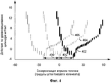
На Фиг.4 показан прогнозируемый график крутящих моментов цилиндра, балансирующий регулировку количества топлива по отношению к синхронизации впрыска топлива при трех разных условиях впрыска топлива. Оси Х и Y такие же, как показано на Фиг.2. Таким образом, описание осей Х и Y опущено для краткости.Figure 4 shows a predicted graph of cylinder torques balancing the adjustment of the amount of fuel relative to the timing of the fuel injection under three different fuel injection conditions. Axes X and Y are the same as shown in FIG. 2. Thus, a description of the X and Y axes is omitted for brevity.
Каждая узкая вертикальная линия 406 соответствует регулировке количества топлива по отношению к базовому количеству топлива и регулировке синхронизации впрыска топлива, уравновешивающей крутящие моменты, производимые цилиндром, в который впрыскивается топливо позднее, чем необходимо. Все вертикальные линии 406 представляют развертку количества впрыскиваемого топлива и синхронизации впрыска топлива для получения равновесия крутящих моментов в цилиндре. Аналогичным образом, каждая штриховая вертикальная линия 404 соответствует регулировке количества топлива по отношению к базовому количеству топлива и регулировке синхронизации впрыска топлива, уравновешивающей крутящие моменты, производимые цилиндром, в который впрыскивается топливо, для форсунки, которая впрыскивает топливо при необходимом положении коленвала двигателя. Все вертикальные линии 404 представляют развертку количества впрыскиваемого топлива и синхронизации впрыска топлива для получения равновесия крутящих моментов в цилиндре. Аналогичным образом, каждая широкая вертикальная линия 402 соответствует регулировке количества топлива по отношению к базовому количеству топлива и регулировке синхронизации впрыска топлива, которая уравновешивает крутящие моменты, производимые цилиндром, в который впрыскивается топливо, для форсунки, которая впрыскивает топливо раньше, чем необходимо. Таким образом, на Фиг.4 показаны данные форсунок, которые производят впрыск в разное время при получении одинакового сигнала управления.Each narrow
Вертикальные линии 402-406 показывают одни и те же характеристики за исключением того, что вертикальные линии 406 сдвинуты влево на графике от вертикальных линий 404 на величину 430. Аналогичным образом, вертикальные линии 402 сдвинуты влево на графике от вертикальных линий 404 на величину 432. Таким образом, когда топливная форсунка впрыскивает топливо позднее, чем необходимо, синхронизацию впрыска топлива необходимо перенести вперед по времени для уравновешивания крутящих моментов, производимых цилиндром.Vertical lines 402-406 show the same characteristics except that
На Фиг.4 линии 404 (т.е. правильно работающая форсунка), 402 (т.е. форсунка, осуществляющая впрыск ранее, чем необходимо) и 406 (т.е. форсунка, осуществляющая впрыск позднее, чем необходимо) показывают, что для каждой форсунки минимальное количество топлива, необходимое для уравновешивания цилиндра, находится в разных интервалах угла положения коленвала по отношению к базовой синхронизации впрыска топлива (например, линии 404). Таким образом, мы видим, что изменение синхронизации впрыска топлива можно определить, определив угол поворота коленвала для регулировки минимального количества топлива по отношению к базовому количеству топлива, а затем сравнив угол поворота коленвала, при котором происходит регулировка минимального количества топлива, с углом поворота коленвала, при котором происходит регулировка минимального количества топлива для других цилиндров топлива. В альтернативном варианте осуществления изобретения угол поворота коленвала, при котором происходит регулировка минимального количества топлива в цилиндре, можно сравнить с прогнозируемым углом поворота коленвала, при котором происходит регулировка минимального количества топлива. Прогнозируемый угол поворота коленвала, при котором происходит регулировка минимального количества топлива, можно сохранить в памяти. Он может быть основан на работе форсунки, работающей, как ожидается (т.е. впрыскивающего топливо с необходимым или прогнозируемым углом поворота коленвала). При сравнении угла поворота, при котором происходит регулировка минимального количества топлива для уравновешивания крутящих моментов цилиндра двигателя, поворот коленвала двигателя, при котором происходит регулировка минимального количества топлива для уравновешивания крутящих моментов цилиндра можно вычесть из прогнозируемого угла поворота коленвала, при котором происходит регулировка минимального количества топлива для уравновешивания крутящих моментов двигателя для вычисления погрешности синхронизации впрыска топлива (в градусах угла поворота коленвала). Если погрешность синхронизации впрыска топлива находится за пределами предопределенного диапазона, может быть определено условие уменьшения эффективности синхронизации впрыска топлива. Например, если предопределенный диапазон находится в пределах j: 10 градусов угла коленвала регулировки синхронизации подачи топлива для уравновешивания крутящих моментов цилиндра и если обнаружено, что синхронизацию подачи топлива необходимо увеличить на 20 градусов угла коленвала для уравновешивания крутящих моментов цилиндра, тогда можно определить условие уменьшения эффективности синхронизации впрыска топлива. Таким образом, можно определить, имеет ли топливная форсунка необходимую синхронизацию по отношению к положению коленвала двигателя.In Fig. 4, lines 404 (i.e., a correctly operating nozzle), 402 (i.e., a nozzle injecting earlier than necessary) and 406 (i.e., a nozzle injecting later than necessary) show that for each nozzle, the minimum amount of fuel necessary to balance the cylinder is in different intervals of the crankshaft position angle with respect to the basic synchronization of fuel injection (for example, line 404). Thus, we see that the change in fuel injection timing can be determined by determining the crankshaft rotation angle to adjust the minimum amount of fuel relative to the base amount of fuel, and then comparing the crankshaft rotation angle at which the minimum amount of fuel is adjusted with the crankshaft rotation angle, at which the minimum amount of fuel is adjusted for other fuel cylinders. In an alternative embodiment, the angle of rotation of the crankshaft at which the minimum amount of fuel in the cylinder is adjusted can be compared with the predicted angle of rotation of the crankshaft at which the minimum amount of fuel is adjusted. The predicted angle of rotation of the crankshaft at which the minimum amount of fuel is adjusted can be stored in memory. It can be based on the operation of the nozzle, which is operating as expected (i.e., injecting fuel with the necessary or predicted angle of rotation of the crankshaft). When comparing the angle of rotation at which the minimum amount of fuel is adjusted to balance the engine cylinder torques, the rotation of the engine crankshaft, at which the minimum amount of fuel is adjusted to balance the cylinder torques, can be subtracted from the predicted angle of the crankshaft at which the minimum amount of fuel is adjusted to balance engine torques to calculate the timing error of fuel injection (in g adusah crank angle). If the timing error of the fuel injection is outside a predetermined range, a condition for decreasing the efficiency of timing of the fuel injection can be determined. For example, if the predetermined range is within j: 10 degrees of the crankshaft angle for adjusting the fuel supply synchronization to balance cylinder torques, and if it is found that the fuel supply synchronization must be increased by 20 degrees of the crankshaft angle for balancing cylinder torques, then the condition for reducing the efficiency can be determined fuel injection timing. Thus, it can be determined whether the fuel injector has the necessary synchronization with respect to the position of the engine crankshaft.
Необходимо упомянуть, что в альтернативном варианте осуществления изобретения вместо того, чтобы найти и сравнить угол поворота коленвала для уравновешивания крутящих моментов цилиндра, можно использовать угол поворота коленвала, при котором впрыскивается минимальное количество топлива, для того, чтобы обеспечить равновесие крутящих моментов в цилиндре, чтобы определить, находится ли количество впрыскиваемого топлива за пределами диапазона. Таким образом, способ, показанный на Фиг.5, может определить угол поворота коленвала, при котором минимальное количество топлива, необходимое для уравновешивания крутящих моментов в цилиндре, определяется несколькими способами. Необходимо также упомянуть, что линии 404 представляют базовую регулировку минимального количества топлива, расстояние 430 можно получить, когда определено абсолютное значение расстояния коленвала между линиями 406 и 404. Аналогичным образом, расстояние 432 можно получить, когда определено абсолютное значение расстояния коленвала между линиями 402 и 404.It is necessary to mention that in an alternative embodiment of the invention, instead of finding and comparing the crankshaft rotation angle to balance cylinder torques, one can use the crankshaft rotation angle at which the minimum amount of fuel is injected in order to balance the torques in the cylinder so that determine if the amount of fuel injected is out of range. Thus, the method shown in FIG. 5 can determine the angle of rotation of the crankshaft at which the minimum amount of fuel needed to balance the torques in the cylinder is determined in several ways. It should also be mentioned that
Необходимо отметить, что, когда определяется отклонение количества впрыскиваемого топлива для равновесия крутящих моментов цилиндра и отклонение синхронизации впрыска топлива для равновесия крутящих моментов, погрешности синхронизации впрыска топлива и количества впрыскиваемого топлива могут быть показаны водителю или устройству диагностики. Необходимо также подчеркнуть, что отклонение количества впрыскиваемого топлива и отклонение синхронизации впрыска топлива основаны на минимальном количестве топлива, необходимом для уравновешивания крутящих моментов цилиндра.It should be noted that when the deviation of the amount of fuel injected to balance the torques of the cylinder and the deviation of the timing of the fuel injection to balance the torques are determined, the timing errors of the fuel injection and the amount of fuel injected can be shown to the driver or diagnostic device. It must also be emphasized that the deviation in the amount of fuel injected and the deviation in timing of the fuel injection are based on the minimum amount of fuel needed to balance the cylinder torques.
Способ, показанный на Фиг.5, выполняют контроллером 12, показанным на Фиг.1. Контроллер 12 может содержать команды проведения операций и расчетов, описанных на Фиг.5. Способ 500 целесообразно использовать при условиях уменьшения эффективности работы форсунки или привода форсунки.The method shown in FIG. 5 is performed by the
На Фиг.5 показана блок-схема способа диагностики работы топливной форсунки согласно одному из вариантов осуществления изобретения. На этапе 502 способ 500 определяет условия работы двигателя. Условия работы двигателя могут включать, в частности, давление впрыска топлива, число оборотов двигателя, синхронизацию впрыска топлива, количество впрыскиваемого топлива, нагрузку на двигатель и температуру двигателя. Способ 500 переходит на этап 504 после определения условий работы двигателя.Figure 5 shows a flowchart of a method for diagnosing the operation of a fuel injector according to one embodiment of the invention. At 502, method 500 determines engine operating conditions. Engine operating conditions may include, but are not limited to, fuel injection pressure, engine speed, fuel injection timing, amount of fuel injected, engine load and engine temperature. Method 500 proceeds to step 504 after determining engine operating conditions.
На этапе 504 способ 500 определяет, присутствуют ли условия для диагностики топливных форсунок. В одном варианте осуществления настоящего изобретения условия для диагностики топливных форсунок присутствуют, когда двигатель работает на холостых оборотах при предопределенной скорости холостого хода и нагрузке. В других вариантах осуществления изобретения условия для диагностики топливных форсунок присутствуют, когда двигатель работает при по существу постоянном числе оборотов двигателя и нагрузке, а число оборотов двигателя и нагрузка выше, чем скорость и нагрузка холостого хода. Таким образом, существует возможность диагностировать работу топливной форсунки при различных условиях работы двигателя.At 504, method 500 determines if conditions are present for diagnosing fuel injectors. In one embodiment of the present invention, conditions for diagnosing fuel injectors are present when the engine is idling at a predetermined idle speed and load. In other embodiments, conditions for diagnosing fuel injectors are present when the engine is running at a substantially constant engine speed and load, and the engine speed and load are higher than the idle speed and load. Thus, it is possible to diagnose the operation of the fuel injector under various engine operating conditions.
На этапе 506 способ 500 определяет базовую синхронизацию впрыска топлива и количество топлива для настоящих условий работы. Базовая синхронизация впрыска топлива может быть вычтена из эмпирически определенной синхронизации впрыска топлива, которая сохранена в памяти. Синхронизация впрыска топлива может относиться к рабочим характеристикам двигателя, экономии топлива и выхлопам. В одном варианте осуществления изобретения базовая синхронизация впрыска топлива выражена через угол поворота коленвала, при котором начинается впрыск. В другом варианте осуществления изобретения базовая синхронизация впрыска топлива выражена через угол поворота коленвала, при котором запланировано окончание впрыска. Импульс впрыска топлива определяется на основании необходимого количества впрыскиваемого топлива, а функция преобразования впрыска соотносит впрыск с количеством впрыскиваемого топлива. В одном варианте осуществления изобретения количество впрыскиваемого топлива определяется при помощи расчета топлива. Например, крутящие моменты привода от датчика положения педали при текущей частоте оборотов двигателя преобразуются в количество воздуха в двигателе и количество топлива. Количество воздуха и топлива можно эмпирически определить или рассчитать на основании геометрии двигателя и эффективного крутящего момента двигателя. Способ 500 переходит на этап 508 после определения базовой синхронизации впрыска топлива и базового количества топлива.At 506, method 500 determines the base timing of the fuel injection and the amount of fuel for the current operating conditions. The basic fuel injection timing can be subtracted from the empirically determined fuel injection timing, which is stored in memory. Fuel injection timing may relate to engine performance, fuel economy, and emissions. In one embodiment of the invention, the basic synchronization of fuel injection is expressed through the angle of rotation of the crankshaft at which the injection begins. In another embodiment of the invention, the basic synchronization of fuel injection is expressed through the angle of rotation of the crankshaft at which the end of the injection is planned. The fuel injection pulse is determined based on the required amount of fuel injected, and the injection conversion function correlates the injection with the amount of fuel injected. In one embodiment of the invention, the amount of fuel injected is determined by calculating the fuel. For example, the drive torques from the pedal sensor at the current engine speed are converted to the amount of air in the engine and the amount of fuel. The amount of air and fuel can be empirically determined or calculated based on engine geometry and effective engine torque. The method 500 proceeds to step 508 after determining the base timing of the fuel injection and the base amount of fuel.
На этапе 508 способ 500 регулирует синхронизацию впрыска топлива и количество впрыскиваемого топлива в соответствии с базовой синхронизацией и базовым количеством топлива. В частности, способ 500 регулирует синхронизацию впрыска топлива и количество топлива для каждого цилиндра двигателя на основании базовой синхронизации впрыска топлива и базового количество топлива. Способ 500 также начинает уравновешивать крутящие моменты на этапе 508. В одном варианте осуществления изобретения способ 500 начинает уравновешивать крутящие моменты, установив синхронизацию впрыска топлива для первой группы цилиндров и количество топлива для второй группы цилиндров. Вторая группа цилиндров может состоять из одного цилиндра или более. В одном варианте осуществления изобретения способ 500 начинает уравновешивать крутящие моменты, одновременно уравновешивая крутящие моменты, производимые двумя цилиндрами двигателя. Цилиндры можно выбрать таким образом, что они будут разделены углом поворота коленвала 360 градусов в порядке запуска двигателя, таким образом, что равновесие крутящих моментов цилиндра не мешает равновесию крутящих моментов другого цилиндра. В одном варианте осуществления изобретения крутящие моменты цилиндра уравновешивают при помощи контроля за отклонениями числа оборотов двигателя при различных вариантах сгорания и при помощи регулировки количества топлива и синхронизации подачи топлива на основании числа оборотов двигателя. Например, если топливо впрыскивается в цилиндр и сгорает, количество топлива, подаваемое в цилиндр, может быть увеличено для уравновешивания крутящих моментов цилиндра, если изменение числа оборотов двигателя (т.е. ускорение) в промежутке угла поворота двигателя, при котором сгораемое топливо преобразуется в крутящие моменты двигателя, меньше числа оборотов двигателя другого цилиндра двигателя, в котором есть базовая синхронизация впрыска и базовое количество впрыскиваемого топлива. В другом варианте осуществления изобретения профиль числа оборотов двигателя цилиндра с правильно работающей топливной форсункой можно сохранить в памяти. Если количество топлива, впрыскиваемое в цилиндр, производит число оборотов двигателя во время интервала угла поворота коленвала, при котором сгораемое топливо преобразуется в крутящие моменты двигателя, меньшее, чем число оборотов двигателя сохраненного профиля, количество топлива, впрыскиваемого в цилиндр, увеличивается. Таким образом, крутящие моменты двигателя могут быть уравновешены при помощи контроля и сравнения увеличения числа оборотов двигателя, вызванного сгоранием топлива в разных цилиндрах двигателя. Если профиль числа оборотов двигателя во время интервала угла поворота коленвала, при котором топливо в уравновешиваемом цилиндре может произвести крутящий момент, соответствует профилю оборотов двигателя других цилиндров или профилю цилиндра, уравновешиваемые цилиндры двигателя достигают равновесного состояния. Способ 500 переходит на этап 510 после регулирования синхронизации впрыска топлива, количества впрыска топлива и начала уравновешивания крутящих моментов цилиндра.At 508, method 500 adjusts the timing of the fuel injection and the amount of fuel injected in accordance with the base timing and the base amount of fuel. In particular, the method 500 controls the timing of the fuel injection and the amount of fuel for each engine cylinder based on the base timing of the fuel injection and the base amount of fuel. The method 500 also begins to balance the torques in step 508. In one embodiment of the invention, the method 500 begins to balance the torques by setting the fuel injection timing for the first group of cylinders and the amount of fuel for the second group of cylinders. The second group of cylinders may consist of one cylinder or more. In one embodiment of the invention, the method 500 begins to balance the torques while balancing the torques produced by the two engine cylinders. Cylinders can be selected in such a way that they will be divided by a 360-degree angle of rotation of the crankshaft in order to start the engine, so that the balance of the torque of the cylinder does not interfere with the balance of the torque of the other cylinder. In one embodiment of the invention, the cylinder torques are balanced by controlling deviations in engine speed for various combustion options and by adjusting the amount of fuel and timing the fuel supply based on the engine speed. For example, if fuel is injected into the cylinder and burns out, the amount of fuel supplied to the cylinder can be increased to balance cylinder torques if a change in engine speed (i.e. acceleration) in the interval of the engine rotation angle at which the combustible fuel is converted to engine torques, less than the engine speed of another engine cylinder, in which there is a basic injection timing and a basic amount of fuel injected. In another embodiment of the invention, the speed profile of a cylinder with a correctly operating fuel injector can be stored. If the amount of fuel injected into the cylinder produces an engine speed during the interval of the crankshaft angle at which the combustible fuel is converted to engine torques less than the engine speed of the stored profile, the amount of fuel injected into the cylinder increases. Thus, engine torques can be balanced by monitoring and comparing the increase in engine speed caused by fuel combustion in different engine cylinders. If the profile of the engine speed during the interval of the crankshaft angle at which the fuel in the balancing cylinder can produce torque corresponds to the profile of the engine speed of the other cylinders or to the profile of the cylinder, the balanced engine cylinders reach an equilibrium state. The method 500 proceeds to step 510 after adjusting the timing of the fuel injection, the amount of fuel injection, and starting to balance the cylinder torques.
На этапе 510 способ 500 сохраняет синхронизацию подачи топлива и количество топлива в тот момент, когда уравновешиваемые крутящие моменты цилиндра были уравновешены. Как описано выше, на этапе 508 можно определить, что крутящие моменты цилиндра уравновешены, когда число оборотов двигателя при интервале угла поворота коленвала, при котором впрыскиваемое топливо преобразуется в крутящие моменты двигателя, по большей части соответствует сохраненному профилю числа оборотов двигателя или числу оборота двигателя прочих цилиндров двигателя. Если способ 500 определит, что крутящие моменты конкретного уравновешиваемого цилиндра находятся в уравновешенном состоянии, параметры регулирования расхода топлива сохраняются в памяти. Например, если определено, что крутящие моменты цилиндра уравновешены, количество впрыскиваемого топлива, угол поворота коленвала при начале впрыска и угол поворота коленвала при окончании впрыска также сохраняются в памяти. Способ 500 переходит на этап 512 после сохранения параметров регулирования расхода топлива в память.At step 510, the method 500 maintains the synchronization of the fuel supply and the amount of fuel at the moment when the balanced torques of the cylinder were balanced. As described above, at step 508, it can be determined that the cylinder torques are balanced when the engine speed at the interval of the crankshaft angle at which the injected fuel is converted to engine torques, for the most part corresponds to the stored profile of the engine speed or other engine speed engine cylinders. If method 500 determines that the torques of a particular balancing cylinder are in a balanced state, fuel control parameters are stored. For example, if it is determined that the cylinder torques are balanced, the amount of fuel injected, the angle of rotation of the crankshaft at the beginning of injection, and the angle of rotation of the crankshaft at the end of injection are also stored. The method 500 proceeds to step 512 after storing the fuel control parameters in memory.
На этапе 512 способ 500 пошагово регулирует количество впрыскиваемого топлива, а начало синхронизации впрыска топлива остается фиксированным. В альтернативном варианте осуществления изобретения конец синхронизации впрыска топлива может быть фиксированным, а количество топлива может регулироваться. Количество впрыскиваемого топлива, подаваемое в цилиндр во время уравновешивания крутящих моментов цилиндра, может быть увеличено во время цикла одного цилиндра и уменьшено во время цикла следующего цилиндра. Таким образом, пошаговая регулировка подачи топлива включает увеличение и уменьшение количества топлива. Количество топлива, добавляемого или вычитаемого из базового количества топлива, может быть предопределенным количеством топлива или незначительной частью дозы топлива цилиндра (т.е. количество впрыскиваемого топлива может регулироваться на 5% от общего количества топлива, впрыскиваемого в цилиндр). По существу, способ 500 начинается с базового количества впрыскиваемого топлива и увеличивает или уменьшает базовое количество топлива, таким образом, чтобы количество топлива, при котором крутящие моменты цилиндра уравновешены, сохранялось на этапе 510. Таким образом, количество топлива, впрыскиваемого в цилиндр, может отличаться от базового количества впрыскиваемого топлива, таким образом, что можно определить минимальное количество топлива, необходимое для уравновешивания крутящих моментов. Способ 500 переходит на этап 514 после пошагового изменения количества топлива.At 512, method 500 adjusts the amount of fuel injected step by step, and the start of fuel injection timing remains fixed. In an alternative embodiment, the end of the fuel injection timing may be fixed, and the amount of fuel may be adjusted. The amount of fuel injected into the cylinder during balancing of the cylinder torques can be increased during the cycle of one cylinder and reduced during the cycle of the next cylinder. Thus, step-by-step adjustment of the fuel supply includes increasing and decreasing the amount of fuel. The amount of fuel added or subtracted from the base amount of fuel may be a predetermined amount of fuel or an insignificant portion of the cylinder fuel dose (i.e., the amount of fuel injected can be adjusted to 5% of the total amount of fuel injected into the cylinder). Essentially, the method 500 begins with a base amount of fuel injected and increases or decreases the base amount of fuel so that the amount of fuel at which the cylinder torques are balanced is stored in step 510. Thus, the amount of fuel injected into the cylinder may differ from the base amount of fuel injected, so that you can determine the minimum amount of fuel needed to balance the torques. The method 500 proceeds to step 514 after a step-by-step change in the amount of fuel.
На этапе 514 способ 500 определяет, завершена ли развертка количества впрыскиваемого топлива. В одном варианте осуществления изобретения развертка завершается, когда предопределенное количество топлива добавлено в базовое количества топлива или вычтено из него. Например, во время одного цикла двигателя к базовому количеству топлива для сгорания может быть добавлено максимум 12 мг/такт. Аналогичным образом, 12 мг/такт может быть вычтено из базового количества топлива для сгорания во время другого цикла двигателя. Таким образом, может быть выполнена развертка количества топлива относительно базового количества топлива. В другом варианте осуществления изобретения количество впрыскиваемого топлива может быть пошагово увеличено по сравнению с базовым количеством топлива, пока характеристика числа оборотов двигателя во время интервала угла поворота коленвала, при котором впрыскиваемое топливо преобразуется в крутящие моменты двигателя, не будет менее интенсивной или пока не будет достигнута предопределенная граница впрыскивания топлива. Аналогичным образом, но во время других циклов двигателя, количество впрыскиваемого топлива может быть пошагово уменьшено по сравнению с базовым количеством топлива, пока характеристика числа оборотов двигателя во время интервала угла поворота коленвала, при котором впрыскиваемое топливо преобразуется в крутящие моменты двигателя, не будет менее интенсивной или пока не будет достигнута предопределенная граница впрыскивания топлива. Если способ 500 определит, что развертка количества впрыскиваемого топлива завершена, способ 500 перейдет на этап 516. В противном случае способ 500 вернется на этап 510.At 514, method 500 determines whether the sweep of the amount of fuel injected has been completed. In one embodiment, the sweep is completed when a predetermined amount of fuel is added to or subtracted from the base amount of fuel. For example, during one engine cycle, a maximum of 12 mg / cycle may be added to the base quantity of fuel for combustion. Similarly, 12 mg / cycle can be subtracted from the base amount of fuel for combustion during another engine cycle. Thus, a sweep of the amount of fuel relative to the base amount of fuel can be performed. In another embodiment, the amount of fuel injected can be incrementally increased compared to the base amount of fuel, while the characteristic of the engine speed during the crankshaft angle interval at which the injected fuel is converted to engine torques is not less intense or until it is reached predefined fuel injection limit. Similarly, but during other engine cycles, the amount of injected fuel can be reduced stepwise compared to the base amount of fuel, while the characteristic of the engine speed during the interval of the crankshaft angle at which the injected fuel is converted to engine torques is not less intense or until a predetermined fuel injection limit is reached. If the method 500 determines that the sweep of the injected fuel quantity is completed, the method 500 proceeds to step 516. Otherwise, the method 500 returns to step 510.
На этапе 516 способ 500 пошагово регулирует начало впрыска топлива синхронизации впрыска. В альтернативном варианте осуществления изобретения способ 500 пошагово регулирует окончание впрыска топлива синхронизации впрыска. В одном варианте осуществления изобретения способ 500 ускоряет синхронизацию впрыска, когда способ переходит на этап 516 во время одного прохождения этапа 516, а затем замедляет синхронизацию впрыска во время последующего прохождения этапа 516. Таким образом, способ 500 может в альтернативных циклах ускорять и замедлять начало синхронизации впрыска. После того, как синхронизация впрыска ускорена или замедлена, способ 500 переходит на этап 518.At step 516, the method 500 incrementally adjusts the start of the injection timing injection of fuel. In an alternative embodiment of the invention, the method 500 incrementally controls the end of the injection timing injection. In one embodiment of the invention, method 500 accelerates injection timing when the method proceeds to step 516 during one passage of step 516, and then slows down injection timing during the subsequent passage of step 516. Thus, method 500 may accelerate and slow down the start of synchronization in alternative cycles. injection. After the injection timing is accelerated or decelerated, the method 500 proceeds to step 518.
На этапе 518 способ 500 определяет, была ли завершена развертка синхронизации впрыска топлива. В одном варианте осуществления изобретения развертка завершена, когда начало впрыска синхронизации впрыска топлива выполняется в предопределенном диапазоне угла поворота коленвала. Например, начало впрыска синхронизации впрыска топлива может отклоняться на±30 градусов угла поворота коленвала для выполнения развертки синхронизации впрыска топлива. Таким образом, развертка синхронизации впрыска топлива по отношению к базовой синхронизации может быть завершена. Диапазон развертки может быть предопределенным углом поворота коленвала или он может зависеть от того, изменяется ли число оборотов двигателя. Например, если число оборотов двигателя начинает снижаться, когда синхронизация впрыска топлива ускоряется, пошаговое ускорение синхронизации впрыска топлива может быть прекращено. Если способ 500 определяет, что развертка синхронизации впрыска топлива завершена, способ 500 переходит на этап 520. В противном случае способ 500 возвращается на этап 510.At 518, method 500 determines whether the fuel injection timing scan has been completed. In one embodiment, the sweep is completed when the start of the fuel injection timing synchronization injection is performed in a predetermined crankshaft angle range. For example, the start of a fuel injection synchronization injection may deviate by ± 30 degrees of the crankshaft rotation angle to perform a fuel injection synchronization scan. Thus, the sweep of the fuel injection timing with respect to the base timing can be completed. The sweep range may be a predetermined angle of rotation of the crankshaft or it may depend on whether the engine speed changes. For example, if the engine speed starts to decrease when the fuel injection timing is accelerated, the stepwise acceleration of the fuel injection timing can be stopped. If method 500 determines that the fuel injection timing scan is completed, method 500 proceeds to step 520. Otherwise, method 500 returns to step 510.
Таким образом, количество впрыскиваемого топлива может различаться (т.е. смещаться) по сравнению с базовым количеством топлива для определения минимального количества топлива, когда достигается равновесие крутящих моментов цилиндра. Кроме того, начало впрыска топлива синхронизации впрыска может отличаться по сравнению с базовым временем начала впрыска таким образом, что образуется схема минимального количества впрыскиваемого топлива для диапазона синхронизации начала впрыска. Например, данные, показанные на Фиг.2, могут быть определены в соответствии со способом, показанным на Фиг.5.Thus, the amount of fuel injected can vary (i.e., shift) compared to the base amount of fuel to determine the minimum amount of fuel when the cylinder torque equilibrium is reached. In addition, the start of the injection synchronization fuel injection may differ from the base injection start time so that a minimum amount of injected fuel is formed for the injection start synchronization range. For example, the data shown in FIG. 2 may be determined in accordance with the method shown in FIG. 5.
На этапе 520 способ 500 сравнивает минимальное количество впрыскиваемого топлива и синхронизацию впрыска, при которой присутствует минимальное количество впрыскиваемого топлива по сравнению с предопределенным количеством впрыскиваемого топлива и синхронизацией впрыска. В одном варианте осуществления изобретения сравнение включает вычитание значений данных, сохраненных на этапе 510, из данных, которые представляют известное ожидаемое количество впрыскиваемого топлива, и синхронизацию впрыска топлива. Способ 500 переходит на этап 522 после сравнения данных количества впрыскиваемого топлива с данными синхронизации впрыска топлива.At step 520, method 500 compares a minimum amount of injected fuel and an injection timing at which a minimum amount of injected fuel is present compared to a predetermined amount of injected fuel and an injection timing. In one embodiment of the invention, the comparison includes subtracting the values of the data stored in step 510 from the data that represent the known expected amount of injected fuel and the timing of the fuel injection. The method 500 proceeds to step 522 after comparing the fuel injection amount data with the fuel injection timing data.
На этапе 522 способ 500 определяет, отличается ли минимальное количество топлива и угол поворота коленвала, при котором используется минимальное количество топлива, от предопределенных диапазонов. Например, если начало синхронизации впрыска топлива находится на 160 градусах угла поворота коленвала до ВМТ такта сжатия, а необходимое начало синхронизации впрыска составляет 175 градусов поворота коленвала до ВМТ такта сжатия, способ 500 может определить условие уменьшения эффективности синхронизации впрыска топлива, когда необходимо отклонение ±10 градусов угла поворота коленвала от 175 градусов угла поворота коленвала. Аналогичным образом способ 500 определяет, выходит ли за пределы диапазона количество впрыскиваемого топлива. Например, если регулируемое количество впрыскиваемого топлива, уравновешивающее крутящие моменты цилиндра, составляет 8 мг/такт, а необходимое количество впрыскиваемого топлива для уравновешивания крутящих моментов цилиндра ограничивается j: 5 мг/такт, способ 500 может означать условие уменьшения эффективности количества впрыска топлива. Если способ 500 определит условие уменьшения эффективности работы форсунки, способ 500 переходит на этап 524. В противном случае способ 500 переходит на этап выхода.At step 522, method 500 determines whether the minimum amount of fuel and the crankshaft angle at which the minimum amount of fuel is used are different from predetermined ranges. For example, if the start of the fuel injection synchronization is at 160 degrees of the crankshaft rotation angle to the TDC of the compression stroke, and the necessary start of the injection synchronization is 175 degrees of the crankshaft rotation to the TDC of the compression stroke, method 500 can determine the condition for reducing the fuel injection timing when the ± 10 deviation is necessary degrees of crankshaft rotation angle from 175 degrees of crankshaft rotation angle. Similarly, method 500 determines whether the amount of fuel injected is out of range. For example, if a controlled amount of injected fuel balancing cylinder torques is 8 mg / cycle and the required amount of injected fuel to balance cylinder torques is limited to j: 5 mg / cycle, method 500 may mean that the fuel injection amount is reduced in efficiency. If the method 500 determines a condition for reducing the efficiency of the nozzle, the method 500 proceeds to step 524. Otherwise, the method 500 proceeds to the exit step.
На этапе 524 способ 500 определяет условия уменьшения эффективности работы форсунки. В одном варианте осуществления изобретения уменьшение эффективности работы форсунки может быть показано водителю транспортного средства или устройству диагностики. Способ 500 переходит на этап выхода после определения условия уменьшения эффективности работы топливной форсунки.At step 524, the method 500 determines the conditions for reducing the efficiency of the nozzle. In one embodiment of the invention, a decrease in nozzle performance may be shown to a driver of a vehicle or a diagnostic device. The method 500 proceeds to the exit step after determining a condition for decreasing the efficiency of the fuel injector.
Таким образом, способ, показанный на Фиг.5, является способом диагностики работы топливной форсунки, который включает в себя: регулировку количества топлива, впрыскиваемого в цилиндр для уравновешивания крутящего момента, произведенного цилиндром, по отношению к другому цилиндру; развертку синхронизации топливного впрыска во время регулировки количества впрыскиваемого топлива; обозначение уменьшения эффективности впрыска топлива, когда минимальное количество топлива, впрыскиваемого в цилиндр для уравновешивания крутящих моментов в цилиндре, когда цилиндр находится за пределами диапазона. Диагностика топливной форсунки включает события, при которых развертка синхронизации впрыска топлива включает регулировку начала или конца синхронизации впрыска по отношению к положению угла коленвала двигателя. Способ диагностики топливной форсунки включает события, при которых уменьшение эффективности - это уменьшение эффективности работы начала или конца синхронизации впрыска топлива. Способ диагностики топливной форсунки определяет события, при которых уменьшение эффективности - это уменьшение эффективности количества топлива, впрыскиваемого в цилиндр. Способ диагностики топливной форсунки включает события, при которых цилиндр - это один из нескольких цилиндров двигателя, а крутящие моменты уравновешиваются для каждого цилиндра из нескольких цилиндров двигателя, и при которых уменьшение эффективности - это уменьшение эффективности количества впрыскиваемого топлива или начала и конца синхронизации впрыскиваемого топлива. Способ диагностики впрыскиваемого топлива включает события, при которых количество топлива, впрыскиваемого в цилиндр, регулируется во время цикла сгорания, в которых начало или конец синхронизации впрыска топлива, по существу, остается постоянным, и при котором начало и конец синхронизации впрыска топлива регулируется во время циклов сгорания, когда количество впрыскиваемого топлива, по существу, остается постоянным. Способ диагностики топливной форсунки включает события, при которых, как минимум, два из множества цилиндров уравновешены во время цикла двигателя.Thus, the method shown in FIG. 5 is a method for diagnosing the operation of a fuel injector, which includes: adjusting the amount of fuel injected into the cylinder to balance the torque produced by the cylinder with respect to the other cylinder; sweep synchronization of fuel injection during adjustment of the amount of injected fuel; designation of a decrease in fuel injection efficiency when the minimum amount of fuel injected into the cylinder to balance the torques in the cylinder when the cylinder is out of range. Diagnostics of the fuel injector include events in which the sweep of the fuel injection timing includes adjusting the start or end of the injection timing with respect to the position of the crankshaft angle of the engine. A method for diagnosing a fuel injector includes events in which a decrease in efficiency is a decrease in the efficiency of the beginning or end of synchronization of fuel injection. A method for diagnosing a fuel injector determines events in which a decrease in efficiency is a decrease in the efficiency of the amount of fuel injected into the cylinder. A method for diagnosing a fuel injector includes events in which a cylinder is one of several engine cylinders, and the torques are balanced for each cylinder of several engine cylinders, and in which a decrease in efficiency is a decrease in the efficiency of the amount of injected fuel or the beginning and end of synchronization of injected fuel. A method for diagnosing injected fuel includes events in which the amount of fuel injected into the cylinder is controlled during the combustion cycle, in which the start or end of the fuel injection timing remains substantially constant, and in which the start and end of the fuel injection timing is controlled during the cycles combustion, when the amount of fuel injected essentially remains constant. A method for diagnosing a fuel injector includes events in which at least two of the plurality of cylinders are balanced during an engine cycle.
Способ, показанный на Фиг. 5, также представляет способ диагностики работы топливной форсунки, который включает в себя: впрыскивание топлива в цилиндр двигателя при первоначальном запуске синхронизации впрыска топлива и окончании синхронизации впрыска топлива; пошаговое выполнение развертки синхронизации впрыска топлива цилиндра, развертку синхронизации впрыска топлива с первоначального запуска развертки синхронизации впрыска топлива или окончания синхронизации впрыска топлива, развертку синхронизации впрыска топлива, которая состоит из множества запусков синхронизации впрыска топлива или из множества окончаний синхронизации впрыска топлива; пошаговое выполнение развертки количества топлива, впрыскиваемого в цилиндр, развертку количества впрыскиваемого топлива в цилиндр, состоящую из множества количеств впрыскиваемого топлива для каждого из множества запусков синхронизации впрыска топлива или множества количеств впрыскиваемого топлива для каждого из множества окончаний синхронизации впрыска топлива; обозначение уменьшения эффективности впрыска топлива, когда минимальное количество впрыскиваемого топлива, необходимого для уравновешивания крутящих моментов, находится за пределами диапазона. Способ включает события, при которых крутящие моменты цилиндра уравновешиваются по отношению к крутящему моменту, производимому другим цилиндром двигателя. Способ включает события, при которых крутящие моменты цилиндра уравновешиваются по отношению к прогнозируемым крутящим моментам цилиндра. Способ включает события, при которых развертка синхронизации впрыска топлива цилиндра выполняется на скорости холостого хода, а также события регулировки синхронизации впрыска топлива при числе оборотов двигателя, отличного от скорости холостого хода, в ответ на развертку синхронизации впрыска топлива цилиндра. Способ включает события, при которых развертка количества топлива, впрыскиваемого в цилиндр, включает увеличение и уменьшение количества топлива, впрыскиваемого в цилиндр. Способ включает события, при которых развертка синхронизации впрыска топлива цилиндра увеличивает и уменьшает угол поворота коленвала двигателя, когда происходит начало или конец впрыска топлива. Способ включает события, при которых обозначение уменьшения эффективности впрыска топлива - это обозначение уменьшения эффективности начала или конца синхронизации впрыска топлива. Способ включает события, при которых обозначение уменьшения эффективности впрыска топлива - это обозначение уменьшения эффективности количества топлива, впрыскиваемого в цилиндр. Способ включает события, при которых обозначение уменьшения эффективности начала или конца синхронизации впрыска топлива происходит в ответ на минимальное количество топлива, впрыскиваемое для уравновешивания крутящих моментов цилиндра за пределами диапазона угла поворота коленвала.The method shown in FIG. 5 also provides a method for diagnosing operation of a fuel injector, which includes: injecting fuel into a cylinder of an engine upon initial start of synchronization of fuel injection and end of synchronization of fuel injection; the step-by-step execution of a cylinder fuel injection synchronization scan, the fuel injection synchronization scan from the initial start of the fuel injection synchronization scan or the end of the fuel injection synchronization, the fuel injection synchronization scan, which consists of a plurality of fuel injection synchronization starts or multiple fuel injection synchronization ends; a step-by-step scan of the amount of fuel injected into the cylinder, a scan of the amount of fuel injected into the cylinder, consisting of a plurality of injected fuel quantities for each of a plurality of fuel injection timing starts or a plurality of injected fuel quantities for each of a plurality of fuel injection timing ends; designation of a decrease in fuel injection efficiency when the minimum amount of fuel injected necessary to balance the torques is out of range. The method includes events in which the cylinder torques are balanced with respect to the torque produced by the other engine cylinder. The method includes events in which the cylinder torques are balanced against the predicted cylinder torques. The method includes events in which the cylinder fuel injection timing scan is performed at idle speed, as well as fuel injection timing adjustment events at an engine speed other than the idle speed, in response to the cylinder fuel injection timing scan. The method includes events in which a scan of the amount of fuel injected into the cylinder includes increasing and decreasing the amount of fuel injected into the cylinder. The method includes events in which a scan of the cylinder fuel injection timing increases and decreases the angle of rotation of the engine crankshaft when the start or end of fuel injection occurs. The method includes events in which the designation of a decrease in fuel injection efficiency is a designation of a decrease in the efficiency of the beginning or end of synchronization of fuel injection. The method includes events in which the designation for reducing the fuel injection efficiency is the designation for decreasing the efficiency of the amount of fuel injected into the cylinder. The method includes events in which the designation of reducing the efficiency of the beginning or end of synchronization of fuel injection occurs in response to the minimum amount of fuel injected to balance the cylinder torques outside the range of the crankshaft rotation angle.
Специалистам в данной области техники должно быть понятно, что способ, показанный на Фиг. 5, может представлять собой одну стратегию обработки или несколько стратегий, например, управляемых событиями, управляемых прерываниями, многозадачных, многопоточных и др. По существу, различные показанные этапы или функции могут быть выполнены в проиллюстрированной последовательности одновременно или опущены. Аналогичным образом, порядок обработки не должен быть обязательно таким, чтобы достигнуть целей, характеристик и преимуществ, описанных настоящим. Он предоставляется для удобства иллюстрации и описания. Хотя это и не показано напрямую, специалистам в данной области понятно, что один или более из показанных этапов, способов или функций могут быть выполнены несколько раз в зависимости от конкретной используемой стратегии.Those skilled in the art will appreciate that the method shown in FIG. 5 may be a single processing strategy or several strategies, for example, event-driven, interrupt-driven, multi-tasking, multi-threaded, etc. In essence, the various steps or functions shown may be performed in the illustrated sequence at the same time or omitted. Similarly, the processing order need not be such as to achieve the objectives, characteristics and advantages described herein. It is provided for the convenience of illustration and description. Although this is not shown directly, those skilled in the art will understand that one or more of the steps, methods, or functions shown can be performed several times depending on the particular strategy used.
Настоящим описание завершается. После прочтения описания специалисты в данной области техники могут осуществить свои изменения и модификации без отклонения от смысла и предмета описания. Например, одноцилиндровый двигатель, двигатели I2, I3, I4, I5, V6, V8, V10, V12 и V16, работающие на природном газе, бензине, дизеле или альтернативном топливе, могут с выгодой использовать настоящее описание.This description concludes. After reading the description, specialists in the art can make their changes and modifications without deviating from the meaning and subject of the description. For example, a single cylinder engine, engines I2, I3, I4, I5, V6, V8, V10, V12 and V16 operating on natural gas, gasoline, diesel or alternative fuels can benefit from the present description.
Claims (20)
регулируют количество топлива, впрыскиваемого в цилиндр, для уравновешивания крутящих моментов, производимых цилиндром, с крутящими моментами, производимыми другим цилиндром;
выполняют развертку синхронизации впрыска топлива в цилиндр во время регулировки количества впрыскиваемого топлива; и
указывают на уменьшение эффективности впрыска топлива, если минимальное количество топлива, впрыскиваемого в цилиндр для уравновешивания крутящих моментов, произведенных цилиндром, находится за пределами рабочего диапазона.1. A method for diagnosing a fuel injector, in which:
adjusting the amount of fuel injected into the cylinder to balance the torques produced by the cylinder with the torques produced by the other cylinder;
perform a scan synchronization of fuel injection into the cylinder during adjustment of the amount of injected fuel; and
indicate a decrease in fuel injection efficiency if the minimum amount of fuel injected into the cylinder to balance the torques produced by the cylinder is outside the operating range.
выполняют впрыск топлива в цилиндр двигателя при первоначальном запуске синхронизации впрыска топлива и при окончании синхронизации впрыска топлива;
пошагово выполняют развертку синхронизации впрыска топлива цилиндра, развертку синхронизации впрыска топлива, начиная с первоначального запуска синхронизации впрыска топлива или окончания синхронизации впрыска топлива, развертку синхронизации впрыска топлива, которая включает множество запусков синхронизации впрыска топлива или множество окончаний синхронизации впрыска топлива;
пошагово выполняют развертку количества топлива, впрыскиваемого в цилиндр, развертку количества топлива, впрыскиваемого в цилиндр, которое состоит из множества количеств впрыскиваемого топлива для каждого из множества запусков синхронизации впрыска топлива или множества количеств впрыскиваемого топлива для каждого из множества окончаний синхронизации впрыска топлива;
указывают на уменьшение эффективности впрыска топлива, когда минимальное количество впрыскиваемого топлива, необходимое для уравновешивания крутящих моментов, находится за пределами диапазона.8. A method for diagnosing the operation of a fuel injector, in which:
performing fuel injection into the engine cylinder at the initial start of synchronization of fuel injection and at the end of synchronization of fuel injection;
perform a step-by-step scan of the cylinder fuel injection synchronization, scan of the fuel injection synchronization, starting from the initial start of the fuel injection synchronization or the end of the fuel injection synchronization, the fuel injection synchronization scan, which includes many fuel injection synchronization starts or multiple fuel injection synchronization ends;
a step-by-step scan of the amount of fuel injected into the cylinder, a scan of the amount of fuel injected into the cylinder, which consists of a plurality of injected fuel quantities for each of a plurality of fuel injection synchronization starts or a plurality of injected fuel quantities for each of a plurality of fuel injection synchronization ends;
indicate a decrease in fuel injection efficiency when the minimum amount of fuel injected needed to balance the torques is out of range.
двигатель;
топливную форсунку, гидравлически соединенную с цилиндром двигателя;
контроллер, который регулирует количество топлива, впрыскиваемого в цилиндр, для уравновешивания крутящих моментов, производимых цилиндром; который производит развертку синхронизации впрыска топлива во время регулировки количества впрыскиваемого топлива; определяет условия уменьшения эффективности начала и конца синхронизации впрыска топлива и условия уменьшения эффективности количества топлива, выпрыскиваемого в цилиндр, когда минимальное количество топлива, впрыскиваемого в цилиндр для уравновешивания крутящего момента, производимого цилиндром, находится за пределами диапазона.17. A system for diagnosing the operation of a fuel injector, which contains:
engine;
a fuel nozzle hydraulically connected to the engine cylinder;
a controller that controls the amount of fuel injected into the cylinder to balance the torques produced by the cylinder; which sweeps the fuel injection timing while adjusting the amount of fuel injected; defines the conditions for decreasing the efficiency of the beginning and end of fuel injection synchronization and the conditions for decreasing the efficiency of the amount of fuel injected into the cylinder when the minimum amount of fuel injected into the cylinder to balance the torque produced by the cylinder is outside the range.
Applications Claiming Priority (2)
| Application Number | Priority Date | Filing Date | Title |
|---|---|---|---|
| US12/950,668 | 2010-11-19 | ||
| US12/950,668 US8051704B2 (en) | 2010-11-19 | 2010-11-19 | Method for diagnosing fuel injectors |
Publications (2)
| Publication Number | Publication Date |
|---|---|
| RU2011147111A RU2011147111A (en) | 2013-05-27 |
| RU2568373C2 true RU2568373C2 (en) | 2015-11-20 |
Family
ID=44340434
Family Applications (1)
| Application Number | Title | Priority Date | Filing Date |
|---|---|---|---|
| RU2011147111/06A RU2568373C2 (en) | 2010-11-19 | 2011-11-21 | Diagnostics of fuel injectors |
Country Status (4)
| Country | Link |
|---|---|
| US (2) | US8051704B2 (en) |
| CN (1) | CN102477909B (en) |
| DE (1) | DE102011086531B4 (en) |
| RU (1) | RU2568373C2 (en) |
Families Citing this family (16)
| Publication number | Priority date | Publication date | Assignee | Title |
|---|---|---|---|---|
| JP4561816B2 (en) * | 2007-11-27 | 2010-10-13 | トヨタ自動車株式会社 | Abnormality determination device and abnormality determination method for internal combustion engine |
| US8161946B2 (en) | 2009-11-20 | 2012-04-24 | Ford Global Technologies, Llc | Fuel injector interface and diagnostics |
| DE102011005283B4 (en) * | 2011-03-09 | 2013-05-23 | Continental Automotive Gmbh | Method for detecting faulty components of an electronically controlled fuel injection system of an internal combustion engine |
| WO2012148418A1 (en) * | 2011-04-29 | 2012-11-01 | International Engine Intellectual Property Company, Llc | Method of compensating for injector aging |
| JP5939119B2 (en) * | 2012-10-03 | 2016-06-22 | トヨタ自動車株式会社 | Cylinder air-fuel ratio variation abnormality detecting device for multi-cylinder internal combustion engine |
| US20140172277A1 (en) * | 2012-12-18 | 2014-06-19 | Caterpillar Inc. | Engine diagnostic system and method |
| JP5918702B2 (en) * | 2013-01-18 | 2016-05-18 | 日立オートモティブシステムズ株式会社 | Engine control device |
| JP5780257B2 (en) * | 2013-03-22 | 2015-09-16 | トヨタ自動車株式会社 | Cylinder air-fuel ratio variation abnormality detecting device for multi-cylinder internal combustion engine |
| DE102013212334A1 (en) | 2013-06-26 | 2014-12-31 | Robert Bosch Gmbh | Method for determining the absolute injection quantity in an internal combustion engine and arrangement therefor |
| GB2518432A (en) | 2013-09-23 | 2015-03-25 | Gm Global Tech Operations Inc | A control apparatus for operating a fuel injector |
| CN103835851B (en) * | 2013-12-06 | 2016-04-06 | 潍柴动力股份有限公司 | A kind of oil sprayer selection method and device |
| DE102015218835B3 (en) * | 2015-09-30 | 2016-11-24 | Continental Automotive Gmbh | Method and apparatus for injecting gaseous fuel |
| CN107288762A (en) * | 2016-04-05 | 2017-10-24 | 新昌县东茗乡宝昱机械厂 | A kind of fuel-displaced limiter assembly of fuel injector arrangements for speed regulation |
| US9945308B2 (en) * | 2016-09-13 | 2018-04-17 | Caterpillar Inc. | Automatic calibration system and method for a dual fuel internal combustion engine |
| US10280863B2 (en) * | 2017-02-02 | 2019-05-07 | Ford Global Technologies, Llc | Fuel injector diagnostics in a variable displacement engine |
| US10208686B1 (en) * | 2017-10-06 | 2019-02-19 | Ford Global Technologies, Llc | Method and system for cylinder imbalance estimation |
Citations (4)
| Publication number | Priority date | Publication date | Assignee | Title |
|---|---|---|---|---|
| US20060293828A1 (en) * | 2005-06-22 | 2006-12-28 | Denso Corporation | Fuel injection controlling apparatus for internal combustion engine |
| US20080053400A1 (en) * | 2006-08-29 | 2008-03-06 | Denso Corporation | Fuel injection controller for internal combustion engine |
| RU2352807C1 (en) * | 2007-10-01 | 2009-04-20 | Рязанский военный автомобильный институт имени генерала армии В.П. ДУБЫНИНА | Method of diagnosing electromechanical jets |
| RU91115U1 (en) * | 2009-09-23 | 2010-01-27 | Государственное образовательное учреждение высшего профессионального образования "РЯЗАНСКИЙ ВОЕННЫЙ АВТОМОБИЛЬНЫЙ ИНСТИТУТ" им. генерала армии В.П. Дубынина | DEVICE FOR DETERMINING THE DEGREE OF POLLUTION AND QUALITY OF SPRAYING FUEL OF ELECTROMAGNETIC NOZZLES |
Family Cites Families (12)
| Publication number | Priority date | Publication date | Assignee | Title |
|---|---|---|---|---|
| US5099814A (en) * | 1989-11-20 | 1992-03-31 | General Motors Corporation | Fuel distributing and injector pump with electronic control |
| US6209520B1 (en) * | 1999-06-15 | 2001-04-03 | Ilya V. Kolmanovsky | Method and apparatus for cylinder balancing |
| US6546912B2 (en) * | 2001-03-02 | 2003-04-15 | Cummins Engine Company, Inc. | On-line individual fuel injector diagnostics from instantaneous engine speed measurements |
| CN1112508C (en) * | 2001-03-30 | 2003-06-25 | 清华大学 | Method and device for diagnosing failure in jet system of diesel engine |
| US6993427B2 (en) | 2002-09-03 | 2006-01-31 | Toyota Jidosha Kabushiki Kaisha | Combustion state estimating apparatus for internal combustion engine |
| ITTO20030837A1 (en) * | 2003-10-23 | 2005-04-24 | Fiat Ricerche | METHOD OF BALANCE OF THE TORQUE GENERATED BY THE CYLINDERS OF AN INTERNAL COMBUSTION ENGINE, IN PARTICULAR A DIESEL ENGINE WITH DIRECT INJECTION PROVIDED WITH A COMMON COLLECTOR INJECTION SYSTEM. |
| CN100432406C (en) * | 2005-06-22 | 2008-11-12 | 株式会社电装 | Fuel injection control apparatus for internal combustion engine |
| EP1923557B1 (en) * | 2006-11-17 | 2009-02-11 | HONDA MOTOR CO., Ltd. | Control system for internal combustion engine |
| JP4298769B2 (en) | 2007-02-07 | 2009-07-22 | 本田技研工業株式会社 | Control device for internal combustion engine |
| DE102007026947B4 (en) * | 2007-06-12 | 2009-06-10 | Continental Automotive Gmbh | Method and device for operating an injection valve |
| JP4525729B2 (en) * | 2007-10-26 | 2010-08-18 | 株式会社デンソー | EGR distribution variation detection device |
| US7823563B2 (en) * | 2008-05-08 | 2010-11-02 | Ford Global Technologies, Llc | Cylinder-by-cylinder balancing of combustion timing in HCCI engines |
-
2010
- 2010-11-19 US US12/950,668 patent/US8051704B2/en not_active Expired - Fee Related
-
2011
- 2011-10-20 US US13/277,691 patent/US8459105B2/en active Active
- 2011-11-17 DE DE102011086531.4A patent/DE102011086531B4/en active Active
- 2011-11-21 RU RU2011147111/06A patent/RU2568373C2/en active
- 2011-11-21 CN CN201110371939.5A patent/CN102477909B/en active Active
Patent Citations (4)
| Publication number | Priority date | Publication date | Assignee | Title |
|---|---|---|---|---|
| US20060293828A1 (en) * | 2005-06-22 | 2006-12-28 | Denso Corporation | Fuel injection controlling apparatus for internal combustion engine |
| US20080053400A1 (en) * | 2006-08-29 | 2008-03-06 | Denso Corporation | Fuel injection controller for internal combustion engine |
| RU2352807C1 (en) * | 2007-10-01 | 2009-04-20 | Рязанский военный автомобильный институт имени генерала армии В.П. ДУБЫНИНА | Method of diagnosing electromechanical jets |
| RU91115U1 (en) * | 2009-09-23 | 2010-01-27 | Государственное образовательное учреждение высшего профессионального образования "РЯЗАНСКИЙ ВОЕННЫЙ АВТОМОБИЛЬНЫЙ ИНСТИТУТ" им. генерала армии В.П. Дубынина | DEVICE FOR DETERMINING THE DEGREE OF POLLUTION AND QUALITY OF SPRAYING FUEL OF ELECTROMAGNETIC NOZZLES |
Also Published As
| Publication number | Publication date |
|---|---|
| US8459105B2 (en) | 2013-06-11 |
| CN102477909B (en) | 2016-08-03 |
| RU2011147111A (en) | 2013-05-27 |
| US20120125089A1 (en) | 2012-05-24 |
| US20110185798A1 (en) | 2011-08-04 |
| DE102011086531A1 (en) | 2012-05-24 |
| DE102011086531B4 (en) | 2023-09-21 |
| CN102477909A (en) | 2012-05-30 |
| US8051704B2 (en) | 2011-11-08 |
Similar Documents
| Publication | Publication Date | Title |
|---|---|---|
| RU2568373C2 (en) | Diagnostics of fuel injectors | |
| RU2573410C2 (en) | Engine fuel supply process (versions) and engine system | |
| US8706386B2 (en) | Method for controlling fuel injection for a dual fuel engine | |
| US7367318B2 (en) | Control system and control method of internal combustion engine | |
| RU2554156C2 (en) | Method of combustion control at low temperature | |
| EP2169202B1 (en) | Control of spark ignited internal combustion engine | |
| US8538664B2 (en) | Controller for diesel engine and method of controlling diesel engine | |
| US20110172898A1 (en) | Internal combustion engine system control device | |
| US6904890B2 (en) | Start-up control of in-cylinder fuel injection spark ignition internal combustion engine | |
| US20130197786A1 (en) | Control apparatus and control method for multi-cylinder internal combustion engine | |
| JP3854209B2 (en) | Fuel injection control device for internal combustion engine | |
| CN102128096B (en) | Multi-pulse injection fuel and load balancing control system | |
| US7254473B2 (en) | Compression ignition engine control apparatus ensuring desired output of torque | |
| RU2704909C2 (en) | System and method for adjusting exhaust valve timing | |
| US9784205B2 (en) | Method and apparatus for controlling internal-combustion engine | |
| US9951711B2 (en) | Control device of engine | |
| JP2010203414A (en) | Control device for internal combustion engine | |
| US9890722B2 (en) | Fuel injection control method for internal combustion engine | |
| JP3876766B2 (en) | Injection rate control device for internal combustion engine | |
| JP3775942B2 (en) | Fuel injection control device for internal combustion engine | |
| US10047692B2 (en) | GDCI cold start misfire prevention | |
| US20010047795A1 (en) | Fuel injection control system for internal combustion engine | |
| JP2019183694A (en) | Cetane number estimation device | |
| JP4407442B2 (en) | Fuel pressure control device for in-cylinder injection engine | |
| US11828244B2 (en) | Fuel injection control method and device for internal combustion engine |
Legal Events
| Date | Code | Title | Description |
|---|---|---|---|
| HE9A | Changing address for correspondence with an applicant | ||
| HE9A | Changing address for correspondence with an applicant |