RU2567832C2 - Dental implant - Google Patents
Dental implant Download PDFInfo
- Publication number
- RU2567832C2 RU2567832C2 RU2013145874/14A RU2013145874A RU2567832C2 RU 2567832 C2 RU2567832 C2 RU 2567832C2 RU 2013145874/14 A RU2013145874/14 A RU 2013145874/14A RU 2013145874 A RU2013145874 A RU 2013145874A RU 2567832 C2 RU2567832 C2 RU 2567832C2
- Authority
- RU
- Russia
- Prior art keywords
- protrusions
- dental implant
- connection
- leg
- indexing
- Prior art date
Links
Images


Classifications
-
- A—HUMAN NECESSITIES
- A61—MEDICAL OR VETERINARY SCIENCE; HYGIENE
- A61C—DENTISTRY; APPARATUS OR METHODS FOR ORAL OR DENTAL HYGIENE
- A61C8/00—Means to be fixed to the jaw-bone for consolidating natural teeth or for fixing dental prostheses thereon; Dental implants; Implanting tools
- A61C8/0048—Connecting the upper structure to the implant, e.g. bridging bars
- A61C8/005—Connecting devices for joining an upper structure with an implant member, e.g. spacers
- A61C8/006—Connecting devices for joining an upper structure with an implant member, e.g. spacers with polygonal positional means, e.g. hexagonal or octagonal
-
- A—HUMAN NECESSITIES
- A61—MEDICAL OR VETERINARY SCIENCE; HYGIENE
- A61C—DENTISTRY; APPARATUS OR METHODS FOR ORAL OR DENTAL HYGIENE
- A61C8/00—Means to be fixed to the jaw-bone for consolidating natural teeth or for fixing dental prostheses thereon; Dental implants; Implanting tools
- A61C8/0048—Connecting the upper structure to the implant, e.g. bridging bars
- A61C8/005—Connecting devices for joining an upper structure with an implant member, e.g. spacers
- A61C8/0066—Connecting devices for joining an upper structure with an implant member, e.g. spacers with positioning means
-
- A—HUMAN NECESSITIES
- A61—MEDICAL OR VETERINARY SCIENCE; HYGIENE
- A61C—DENTISTRY; APPARATUS OR METHODS FOR ORAL OR DENTAL HYGIENE
- A61C8/00—Means to be fixed to the jaw-bone for consolidating natural teeth or for fixing dental prostheses thereon; Dental implants; Implanting tools
- A61C8/0048—Connecting the upper structure to the implant, e.g. bridging bars
- A61C8/005—Connecting devices for joining an upper structure with an implant member, e.g. spacers
- A61C8/0068—Connecting devices for joining an upper structure with an implant member, e.g. spacers with an additional screw
-
- A—HUMAN NECESSITIES
- A61—MEDICAL OR VETERINARY SCIENCE; HYGIENE
- A61C—DENTISTRY; APPARATUS OR METHODS FOR ORAL OR DENTAL HYGIENE
- A61C8/00—Means to be fixed to the jaw-bone for consolidating natural teeth or for fixing dental prostheses thereon; Dental implants; Implanting tools
- A61C8/0048—Connecting the upper structure to the implant, e.g. bridging bars
- A61C8/005—Connecting devices for joining an upper structure with an implant member, e.g. spacers
- A61C8/0069—Connecting devices for joining an upper structure with an implant member, e.g. spacers tapered or conical connection
- A61C8/0071—Connecting devices for joining an upper structure with an implant member, e.g. spacers tapered or conical connection with a self-locking taper, e.g. morse taper
-
- A—HUMAN NECESSITIES
- A61—MEDICAL OR VETERINARY SCIENCE; HYGIENE
- A61C—DENTISTRY; APPARATUS OR METHODS FOR ORAL OR DENTAL HYGIENE
- A61C8/00—Means to be fixed to the jaw-bone for consolidating natural teeth or for fixing dental prostheses thereon; Dental implants; Implanting tools
- A61C8/0048—Connecting the upper structure to the implant, e.g. bridging bars
- A61C8/0077—Connecting the upper structure to the implant, e.g. bridging bars with shape following the gingival surface or the bone surface
-
- F—MECHANICAL ENGINEERING; LIGHTING; HEATING; WEAPONS; BLASTING
- F04—POSITIVE - DISPLACEMENT MACHINES FOR LIQUIDS; PUMPS FOR LIQUIDS OR ELASTIC FLUIDS
- F04C—ROTARY-PISTON, OR OSCILLATING-PISTON, POSITIVE-DISPLACEMENT MACHINES FOR LIQUIDS; ROTARY-PISTON, OR OSCILLATING-PISTON, POSITIVE-DISPLACEMENT PUMPS
- F04C2270/00—Control; Monitoring or safety arrangements
- F04C2270/04—Force
- F04C2270/042—Force radial
- F04C2270/0421—Controlled or regulated
Abstract
Description
Предлагаемое изобретение касается зубного имплантата, относящегося к области оральной имплантологии.The present invention relates to a dental implant related to the field of oral implantology.
Зубные имплантаты обеспечивают имплантацию протеза (замены зуба) в челюстные кости, при этом они чаще всего содержат два основных элемента:Dental implants provide implantation of a prosthesis (tooth replacement) in the jaw bones, while they most often contain two main elements:
- с одной стороны, имплантат, выполненный в форме винта, снабженного глухим отверстием, который должен быть закреплен ввинчиванием в указанных челюстных костях, и- on the one hand, an implant made in the form of a screw provided with a blind hole, which must be fixed by screwing in the specified jaw bones, and
- с другой стороны, протезный элемент или ножка, служащая опорой собственно протезу или замене зуба.- on the other hand, the prosthetic element or leg, which serves as a support for the prosthesis itself or replacement of the tooth.
Соединительные средства позволяют скрепить предварительно вместе ножку, служащую опорой для протеза, и имплантат при опробовании его во рту или, окончательно, при конечной операции по установке протеза в полости рта.The connecting means allow you to pre-hold together the leg, which serves as a support for the prosthesis, and the implant when testing it in the mouth or, finally, during the final operation to install the prosthesis in the oral cavity.
Согласно известному, давно используемому методу соединения, соединительные средства сочетают соединение в паз типа зажимного конуса (cône-morse) и антиротационную систему индексации, которая включает индексирующий выступ и комплементарную гомотетическую полость, которыми снабжены соответственно соединяемые в паз концы составных элементов имплантата (см., например, патентные документы FR-2.922.752 и US-2010/0248181). Винт обеспечивает жесткое скрепление обоих составных элементов в осевом направлении. Охватывающие и охватываемые составные элементы описанных в обоих вышеназванных документах систем индексации содержат соответственно одинаковое число равноудаленных выступов и пазов.According to the well-known long-used method of connection, the connecting means combine the connection into a groove of the clamping cone type (cône-morse) and an anti-rotation indexing system, which includes an indexing protrusion and a complementary homothetic cavity, with which the ends of the components of the implant are respectively connected into the groove (see, for example, patent documents FR-2.922.752 and US-2010/0248181). The screw provides a rigid fastening of both components in the axial direction. The female and male components of the indexing systems described in both of the above documents contain the same number of equally spaced protrusions and grooves.
Согласно документу FR-2.922.752, антиротационная система содержит выступ, состоящий из контактного элемента треугольного равностороннего сечения, которым снабжен апикальный конец корневой части, и комплементарной гомотетической полости, образованной в основании ножки. Эта система имеет недостаток, поскольку она не решает проблему, поставленную необходимостью создания возможности как можно более точного позиционирования протеза в полости рта. Действительно, это устройство предлагает лишь три возможности ориентации протеза, разнесенные на 120° вокруг оси его имплантации, что недостаточно для достижения хорошей ориентации протеза как в функциональном плане, так и в эстетическом плане.According to FR-2.922.752, the anti-rotation system comprises a protrusion consisting of a contact element of a triangular equilateral section, which is provided with the apical end of the root part, and a complementary homothetic cavity formed at the base of the leg. This system has a drawback because it does not solve the problem posed by the need to create the possibility of the most accurate positioning of the prosthesis in the oral cavity. Indeed, this device offers only three possibilities for orienting the prosthesis, spaced 120 ° around the axis of its implantation, which is not enough to achieve a good orientation of the prosthesis, both functionally and aesthetically.
Эту проблему не решает также зубной имплантат, описанный в документе US-2010/0248181. Действительно, согласно этому документу, система антиротационной индексации содержит с одной стороны индексирующий гексагональный рельефный элемент, образованный торцом основания ножки и, с другой стороны, гомотетическую полость в верхней части имплантата. Это устройство предлагает больше возможностей ориентации протеза вокруг его оси крепления (точнее, шесть возможностей, смещенных на 60° вокруг оси имплантации протеза). Однако эту систему индексации трудно реализовать в связи с очень небольшим размером взаимодействующих в ней компонентов, между тем как установка протеза может оказаться трудной именно потому, что речь идет о его установке в очень труднодоступной части полости рта (например, в случае моляров).The dental implant described in US-2010/0248181 also does not solve this problem. Indeed, according to this document, the anti-rotation indexing system contains, on the one hand, an indexing hexagonal relief element formed by the end face of the leg base and, on the other hand, a homothetic cavity in the upper part of the implant. This device offers more options for orienting the prosthesis around its axis of attachment (more precisely, six possibilities offset 60 ° around the axis of implantation of the prosthesis). However, this indexing system is difficult to implement due to the very small size of the components interacting in it, while installing a prosthesis can be difficult precisely because it is about installing it in a very inaccessible part of the oral cavity (for example, in the case of molars).
Другой зубной имплантат также предлагает шесть смещенных на 60° позиций вокруг оси имплантации протеза. Этот имплантат описан в документе US-2010/0055643. Согласно этому документу, система антиротационной индексации содержит, с одной стороны, индексирующий треугольный рельефный элемент на ножке и, с другой стороны, полость с шестью прорезями, равномерно разнесенными вокруг оси зубного имплантата, которая выполнена в верхней части имплантата. Однако этот имплантат содержит большие недостатки, а именно, что усилия передаются лишь верхней коронковой частью, содержащей прорези. Это индуцирует микродвижения имплантата, а именно в процессе жевания. Эти микродвижения приводят к инфильтрации биологических жидкостей и бактерий, которые могут размножаться в имплантате.Another dental implant also offers six 60 ° positions around the axis of implantation of the prosthesis. This implant is described in US-2010/0055643. According to this document, the anti-rotation indexing system contains, on the one hand, an indexing triangular relief element on the leg and, on the other hand, a cavity with six slots evenly spaced around the axis of the dental implant, which is made in the upper part of the implant. However, this implant contains great disadvantages, namely that the forces are transmitted only by the upper coronal part containing the slots. This induces micromotion of the implant, namely during chewing. These micromotion lead to the infiltration of biological fluids and bacteria that can multiply in the implant.
Задача предлагаемого изобретения состоит в разработке зубного имплантата, который позволяет устранить указанные выше недостатки. Зубной имплантат согласно изобретению содержит, как известно, корневую часть или собственно имплантат, имеющий форму винта, снабженного глухим отверстием, и ножку, предусмотренную для опоры протезного зуба, причем этот имплантат и эта ножка снабжены комплементарными соединительными средствами, содержащими, с одной стороны, систему индексации, составные части которой могут быть соединены посредством наложения внахлест или разъемным соединением, причем охватываемый элемент этой системы индексации, образованный дистальным концом или основанием протезного элемента или ножки, содержит, по меньшей мере, два выступа с одинаковым угловым разносом, и, с другой стороны, полость, образующую охватывающий элемент этого индексирующего устройства, выполненного в отверстии корневой части, который содержит лепестки или выемки, разнесенные равномерно одни от других, число которых является кратным числу выступов указанного охватываемого элемента, причем этот имплантат отличается главным образом комбинацией индексирующего устройства с системой соединения, согласно которой части взаимодействующих концов ножки и корневая часть выполнены таким образом, что обеспечивают соединение в паз указанной ножки и указанного корневой части посредством системы соединения типа зажимного конуса (cône-morse). Согласно возможной форме осуществления, охватываемый элемент системы индексации содержит два выступа, с угловым разносом на 180°, в то время как охватывающий элемент индексирующего устройства содержит четыре лепестка, разнесенных на 90°, или шесть лепестков, разнесенных на 60°.The task of the invention is to develop a dental implant that can eliminate the above disadvantages. The dental implant according to the invention contains, as you know, the root part or the actual implant, in the form of a screw provided with a blind hole, and a leg provided for supporting the prosthetic tooth, moreover, this implant and this leg are provided with complementary connecting means containing, on the one hand, the system indexing, the components of which can be joined by overlapping or detachable connection, moreover, the covered element of this indexing system, formed by the distal end or the new prosthetic element or legs, contains at least two protrusions with the same angular spacing, and, on the other hand, a cavity forming a covering element of this indexing device, made in the hole of the root part, which contains petals or recesses spaced uniformly one from others, the number of which is a multiple of the number of protrusions of the specified male element, and this implant differs mainly in the combination of an indexing device with a connection system, according to which The interacting ends of the legs and the root part are made in such a way that they provide a connection into the groove of the specified leg and the specified root part by means of a clamping cone-type coupling system (cône-morse). According to a possible embodiment, the male element of the indexing system comprises two protrusions with an angular spacing of 180 °, while the female element of the indexing device contains four petals 90 ° apart or six petals 60 ° apart.
Согласно другому предпочтительному варианту осуществления, охватываемый элемент системы индексации содержит три выступа, разнесенных на 120°, а полость, образующая охватывающий элемент этого индексирующего устройства, содержит шесть выемок или лепестков, разнесенных на 60°.According to another preferred embodiment, the male element of the indexing system comprises three protrusions spaced 120 ° apart, and the cavity forming the female element of this indexing device comprises six recesses or petals spaced 60 ° apart.
Следовательно, имплантат снабжен шестилепестковым охватывающим соединением, между тем как ножка снабжена охватываемым соединением с тремя выступами.Therefore, the implant is equipped with a six-petaled female connection, while the leg is equipped with a male connection with three protrusions.
Таким образом, при соединении посредством взаимного наложения охватываемых и охватывающих компонентов этого соединительного устройства три выступа охватываемого компонента могут быть, выборочно, вставлены в три разнесенные на 120° выемки охватывающих компонентов.Thus, when connected by interposing the male and female components of this connecting device, the three protrusions of the male component can be selectively inserted into three 120 ° grooves of the female components.
Так что могут быть созданы шесть положений ножки относительно имплантата и, следовательно, шесть возможностей ориентации протезного зуба вокруг его оси имплантации, что обеспечивает его хорошее позиционирование как в отношении функции, которую он призван выполнять, так и в эстетическом плане зубного ряда. Согласно предпочтительному варианту осуществления, нижний конец выступов содержит входную галтель.So, six positions of the leg relative to the implant can be created and, therefore, six possibilities of orienting the prosthetic tooth around its axis of implantation, which ensures its good positioning both in relation to the function it is called upon to perform and in the aesthetic plan of the dentition. According to a preferred embodiment, the lower end of the protrusions comprises an inlet fillet.
Изобретение имеет ряд других преимуществ:The invention has several other advantages:
- упрощает установку протезного зуба;- simplifies the installation of the prosthetic tooth;
- позволяет снизить значение поверхностей индексирующего устройства, находящегося в контакте после установления этого контакта, так что ограничивается трение. Согласно изобретению, ножка имеет индексацию с тремя вершинами, позиционированными с разносом на 120°, которая сохраняет возможность позиционирования с разносом на 60° и предлагает благоприятные условия для уменьшения зон трения и рисков нежелательных помех, вызванных радиусом галтелей, предусмотренных на нижних концах выступов системы индексации. Удобная установка во рту делает интуитивной интервенцию врача независимо от местонахождения имплантации. Также значительно уменьшен угловой зазор при изготовлении, что повышает точность устройства;- allows to reduce the value of the surfaces of the indexing device in contact after the establishment of this contact, so that friction is limited. According to the invention, the foot has indexing with three vertices positioned with a spacing of 120 °, which retains the ability to position with a spacing of 60 ° and offers favorable conditions to reduce friction zones and the risks of unwanted interference caused by the radius of the fillets provided at the lower ends of the protrusions of the indexing system . A convenient installation in the mouth makes intuitive the intervention of a doctor regardless of the location of implantation. The angular clearance during manufacturing is also significantly reduced, which increases the accuracy of the device;
- комбинация техники соединения, включающей при имплантации специальную шестилепестковую полость и соединение типа зажимного конуса на значительной высоте, гарантирует полную герметичность между протезом и имплантатом;- the combination of the connection technique, which includes a special six-petal cavity during implantation and the connection of the clamping cone type at a considerable height, guarantees complete tightness between the prosthesis and the implant;
- благодаря инновационной геометрии эта техника соединения обеспечивает оптимальную и надежную передачу крутящего момента при установке имплантата. Таким образом, исключаются все риски расплющеваний и других деформаций, связанных с передачей момента. При протезировании герметичность обеспечивается геометрией типа зажимного конуса. Это технологическое решение позволяет, таким образом, использовать две различные концепции, которые не изменяют качественных показателей протезирования, а именно:- Thanks to innovative geometry, this joint technique ensures optimal and reliable torque transmission during implant placement. Thus, all risks of flattening and other deformations associated with the transmission of torque are eliminated. When prosthetics, tightness is ensured by geometry like clamping cone. This technological solution allows, therefore, to use two different concepts that do not change the quality indicators of prosthetics, namely:
- ротационное устройство;- rotation device;
- антиротационное устройство.- anti-rotation device.
Изобретение относится к системе сопряжения зубной имплантат - протезная ножка, которая обеспечивает удобное изменение позиционирования, точную индексацию и полную герметичность. Оптимизация в отношении размеров позволяет получить:The invention relates to a system for pairing a dental implant - a prosthetic leg, which provides a convenient change in positioning, accurate indexing and complete tightness. Size optimization allows you to get:
- единую полость для всех диаметров имплантатов: в дальнейшем исключается выбор протезных элементов в зависимости от диаметров имплантатов;- a single cavity for all implant diameters: the choice of prosthetic elements depending on the implant diameters is subsequently excluded;
- удобные условия изготовления вследствие того, что охватываемый элемент соединения содержит лишь три выступа.- convenient manufacturing conditions due to the fact that the male connection element contains only three protrusions.
Вышеназванные, а также другие цели, признаки и преимущества становятся более очевидными из нижеследующего описания и прилагаемых чертежей, на которых:The above, as well as other objectives, features and advantages become more apparent from the following description and the accompanying drawings, in which:
Фиг. 1 изображает вид в изометрии с пространственным разделением деталей зубного имплантата согласно изобретению,FIG. 1 is an exploded perspective view of a dental implant according to the invention,
Фиг. 2 - вид в осевом разрезе этого зубного имплантата с пространственным разделением деталей,FIG. 2 is a view in axial section of this dental implant with a spatial separation of the parts,
Фиг. 3 - вид в осевом разрезе, показывающий составные элементы зубного имплантата в положении сборки,FIG. 3 is an axial sectional view showing the components of a dental implant in an assembly position,
Фиг. 4 - вид в разрезе по линии 4-4 с фиг. 2,FIG. 4 is a sectional view taken along line 4-4 of FIG. 2
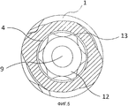
Фиг. 5 - вид в разрезе по линии 5-5 с фиг. 2,FIG. 5 is a sectional view taken along line 5-5 of FIG. 2
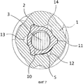
Фиг. 6 и 7 изображают виды в поперечном разрезе, иллюстрирующие два положения при соединении наложением внахлест соединительного охватываемого элемента с тремя выступами на протезной ножке на охватывающую шестилепестковую полость соединительного устройства согласно изобретению.FIG. Figures 6 and 7 are cross-sectional views illustrating two positions when overlapping by overlapping a connecting male element with three protrusions on a prosthetic leg on a female six-petal cavity of the connecting device according to the invention.
На эти чертежи делаются ссылки при описании искомого неограничивающего варианта осуществления зубного имплантата согласно изобретению.These drawings are referenced in the description of the desired non-limiting embodiment of a dental implant according to the invention.
В нижеследующем описании:In the following description:
- выражением «зубной имплантат» обозначена совокупность двух основных составных частей протезного устройства;- the expression "dental implant" means the combination of the two main components of the prosthetic device;
- термином «базис анкеровки» обозначен собственно имплантат или корневая часть;- the term "anchoring base" refers to the actual implant or root part;
- термином «ножка» обозначен протезный элемент или искусственная культя, предусмотренные для создания опоры протеза или замены зуба;- the term “leg” refers to the prosthetic element or artificial stump provided for supporting the prosthesis or replacing the tooth;
- термином «дистальный» обозначен конец элементов, составляющих имплантат, который призван находиться ближе всего относительно дна отверстия, проделанного в кости, для приема коренного элемента зубного имплантата, а термином «проксимальный» обозначен наиболее удаленный конец относительно этого дна.- the term "distal" indicates the end of the elements that make up the implant, which is designed to be closest to the bottom of the hole made in the bone to receive the root element of the dental implant, and the term "proximal" refers to the most distant end relative to this bottom.
Зубной имплантат согласно изобретению, как известно, включает:The dental implant according to the invention is known to include:
- корневую часть 1 или собственно имплантат;-
- ножку 2 или искусственную культю, предусмотренную для создания опоры протезного зуба или замены зуба (не показан), причем эта ножка 2 предназначена для герметичного соединения с указанной корневой частью;-
- осевой винт 3, который позволяет жестко скрепить базис 1 с ножкой 2.-
Корневая часть 1, которая представляет собой корневой элемент имплантата, предусмотрена для анкеровки в верхнечелюстной кости или в нижнечелюстной кости пациента.The
Она принимает форму конусного или цилиндро-конусного винта, который содержит глухое отверстие 4, выходящее к проксимальному концу базиса 1. Ее наружная поверхность может быть выполнена шероховатой любым известным приемлемым способом. Она изготовлена из биоматериала, предпочтительно титана или циркония, или из сплавов титана или циркония, причем оба эти материала имеют преимущества в том, что они обладают высокими качественными показателями механической прочности, неизменяемости и повышенной биосовместимостью с костными тканями. Ножка 2, образующая супраструктуру имплантата, представляет собой продолговатый элемент, снабженный осевым отверстием 5, которое пересекает его из конца в конец.It takes the form of a cone or cylinder-cone screw, which contains a
Ножка 2 также выполнена из биоматериала, предпочтительно титана или циркония или из сплавов титана или циркония.
Проксимальная часть 7 корневой части 1 и дистальная часть 8 супраструктуры 2 выполнены комплементарными, что обеспечивает, как известно, соединение в паз этих частей.The
Прочность этого соединения обеспечивает винт 3, помещенный в осевое отверстие 5 ножки 2 и вворачиваемый в резьбу 9, выполненную в дне глухого отверстия 4 корневой части 1. С другой стороны, комплементарные соединительные средства содержат также систему индексации, составные элементы которой могут быть соединены посредством наложения внахлест или выборочно разъемным соединением. Охватываемый элемент 10 системы индексации, образованный дистальным концом или основанием протезного элемента или ножки 2, содержит, по меньшей мере, два радиальных выступа 11 с одинаковым угловым разносом, и, с другой стороны, полость, образующую охватывающий элемент этого индексирующего устройства, выполненного в отверстии 4 корневой части 1, который содержит лепестки или выемки 13, расположенные на равном удалении одни относительно других, число которых является кратным числу выступов 11 указанного охватываемого элемента 2. Согласно возможному варианту осуществления (не показан), охватываемый элемент системы индексации содержит два радиальных выступа, разнесенных на 180°, в то время как охватывающий элемент индексирующего устройства снабжен четырьмя лепестками, разнесенными на 90°, или шестью лепестками, разнесенными на 60°. Согласно представленному на чертеже предпочтительному и преимущественному варианту осуществления, охватываемый элемент 10 системы индексации содержит три радиальных выступа 11, разнесенных на 120°, а полость 12, образующая охватывающий элемент этого индексирующего устройства, снабжена шестью выемками или лепестками, разнесенными на 60°.The strength of this connection is provided by a
Выступы 11 и выемки 13 этого индексирующего устройства выполнены таким образом, что они могут быть выборочно вставлены со сцеплением без чрезмерного зазора в три разнесенные на 120° выемки или лепестки полости.The
Полость 12, образующая охватывающий элемент системы индексации, получена, например, как известно, прошиванием.The
Дистальный конец или основание ножки 2 выполнен кольцеобразной цапфой 14 с меньшим диаметром, чем в остальной части указанной ножки, с которой она соединена. Выступы 11 равноудалены от периферии этой кольцеобразной цапфы и простираются параллельно оси указанной кольцеобразной цапфы и на всю ее высоту. Радиальные выступы 11 имеют в целом треугольный профиль с округленной вершиной.The distal end or base of the
Конец выступов 11 снабжен входной галтелью 11а. Эта характеристика позволяет врачу интуитивно соединить в паз обе составные части имплантата, то есть ножку 2 и корневую часть 1.The end of the
Согласно другому отличительному положению изобретения, описанное выше индексирующее устройство комбинируется с системой соединения, согласно которой части взаимодействующих концов ножки 2 и корневой части 1 выполнены таким образом, что обеспечивают их соединение в паз посредством системы соединения типа зажимного конуса. Согласно этой известной системе соединения, соединяемые части ножки 2 и корневая часть 1, которые должны находиться в контакте, снабжены комплементарными конусными поверхностями соответственно 2а и 1а. Эта конусность имеет, например, угловой показатель порядка 10° и простирается на значительную высоту, например, порядка 2,5 мм. Таким образом, соединение (bridage) между зубным имплантатом 1 и протезной фазой 2 простирается лишь на поверхность двух зажимных конусов 1а, 2а, обеспечивая соединение корневой части 1 и ножки 2 по типу длинной центровки. Оба зажимных конуса 1а, 2а приводятся в соответствие на высоте определенной калиброванной плоскости. Выбор соединения типа зажимный конус позволяет, как известно, добиться полной герметичности между ножкой 2 и корневой частью 1. Как показано на фиг. 2, корневая часть 1 имеет внутри, снизу вверх, резьбовой участок 9, за которым следует шестилепестковая полость 12 и, наконец, охватывающая поверхность 1а типа зажимного конуса в своей апикальной части.According to another distinguishing feature of the invention, the indexing device described above is combined with a joining system, according to which parts of the interacting ends of the
Как и прежде согласно фиг. 2, ножка 2 содержит снаружи и снизу вверх охватываемую поверхность 2а типа зажимного конуса и поверхность 15 приема протезного зуба.As before according to FIG. 2, the
В этом случае, комбинация этого типа соединения с описанной выше оригинальной системой индексации способствует упрощению установки стоматологом-хирургом протезной опоры 2 в корневой части 1 и хорошему позиционированию.In this case, the combination of this type of connection with the original indexing system described above helps to simplify the installation by the dentist-surgeon of the
Фигуры 6 и 7 иллюстрируют два положения ножки 2, смещенные на 60° относительно корневой части 1. На этих фигурах исходная поверхность S изображена жирной линией, и можно видеть, что на фиг. 7 эта поверхность S сместилась на 60° по часовой стрелке относительно ориентации, представленной на фиг. 6.Figures 6 and 7 illustrate two positions of the
Claims (7)
Applications Claiming Priority (3)
| Application Number | Priority Date | Filing Date | Title |
|---|---|---|---|
| FR11/00769 | 2011-03-15 | ||
| FR1100769A FR2972625B1 (en) | 2011-03-15 | 2011-03-15 | DENTAL IMPLANT |
| PCT/FR2012/000093 WO2012123654A1 (en) | 2011-03-15 | 2012-03-15 | Dental implant |
Publications (2)
| Publication Number | Publication Date |
|---|---|
| RU2013145874A RU2013145874A (en) | 2015-04-20 |
| RU2567832C2 true RU2567832C2 (en) | 2015-11-10 |
Family
ID=45974370
Family Applications (1)
| Application Number | Title | Priority Date | Filing Date |
|---|---|---|---|
| RU2013145874/14A RU2567832C2 (en) | 2011-03-15 | 2012-03-15 | Dental implant |
Country Status (7)
| Country | Link |
|---|---|
| EP (1) | EP2685929B2 (en) |
| CN (1) | CN103458819A (en) |
| ES (1) | ES2541027T5 (en) |
| FR (1) | FR2972625B1 (en) |
| PT (1) | PT2685929E (en) |
| RU (1) | RU2567832C2 (en) |
| WO (1) | WO2012123654A1 (en) |
Families Citing this family (6)
| Publication number | Priority date | Publication date | Assignee | Title |
|---|---|---|---|---|
| EP2829250B1 (en) * | 2013-07-26 | 2020-05-13 | SIC Invent AG | Dental implant, abutment, implant system and implantation set |
| CN106109035A (en) * | 2016-08-26 | 2016-11-16 | 深圳市倍康美医疗电子商务有限公司 | Base station and dentition defect that a kind of free bonding connects plant top prosthetic device |
| JP7299870B2 (en) * | 2017-03-20 | 2023-06-28 | ストラウマン ホールディング アーゲー | Implant system |
| ES2663539B2 (en) * | 2017-12-05 | 2018-07-12 | Julián CUESTA GARCIA | Highly self-tapping dental implant system with hybrid connection and parallel double cone block between the prosthetic abutment, the implant and the internal screw. |
| CH714924A1 (en) * | 2018-04-23 | 2019-10-31 | Denta Vision Gmbh | Calibration of various devices in the digital workflow of a production process. |
| IT202000030014A1 (en) * | 2020-12-04 | 2022-06-04 | I D I Evolution S R L | ADAPTER DEVICE IN A DENTAL PROSTHETIC IMPLANT |
Citations (2)
| Publication number | Priority date | Publication date | Assignee | Title |
|---|---|---|---|---|
| RU2273464C2 (en) * | 2003-06-11 | 2006-04-10 | Фикрет Мавлудинович Абдуллаев | Dental implant and method for carrying out inraosseous implantation |
| WO2009009911A1 (en) * | 2007-07-16 | 2009-01-22 | Dentalpoint Ag | Dental implant |
Family Cites Families (13)
| Publication number | Priority date | Publication date | Assignee | Title |
|---|---|---|---|---|
| US5116225A (en) * | 1990-10-17 | 1992-05-26 | Riera Juan C A | Angulated abutment for osseointegrated implants |
| DE19534979C1 (en) † | 1995-09-20 | 1997-01-09 | Imz Fertigung Vertrieb | Endosseous single tooth implant with anti-rotation device |
| US7249949B2 (en) † | 2004-06-29 | 2007-07-31 | Lifecore Biomedical, Inc. | Internal connection dental implant |
| ES2307352B1 (en) * | 2005-04-12 | 2009-09-18 | Bti, I+D, S.L. | DENTAL IMPLANT AND PARTS INTENDED TO BE CONNECTED TO A DENTAL IMPLANT, AND THE INTERNAL CONNECTION BETWEEN THE DENTAL IMPLANT AND EACH PIECE. |
| EP2260788B1 (en) † | 2005-06-03 | 2024-03-13 | Straumann Holding AG | Improved coupling for a multi-part dental implant system |
| WO2008071368A1 (en) * | 2006-12-14 | 2008-06-19 | Friadent Gmbh | Arrangement for insertion of implants |
| US9095397B2 (en) | 2006-12-14 | 2015-08-04 | Friadent Gmbh | Arrangement for insertion of implants |
| US7806693B2 (en) * | 2007-04-23 | 2010-10-05 | Nobel Biocare Services Ag | Dental implant |
| FR2922752B1 (en) | 2007-10-31 | 2010-11-19 | Tekka | DENTAL IMPLANT WITH MALE TRUNK CONNECTOR. |
| CN101249024A (en) * | 2008-03-12 | 2008-08-27 | 威海威高生物技术有限公司 | Mouth cavity planting body device |
| CN100591300C (en) * | 2008-06-12 | 2010-02-24 | 方巍 | Pipe sleeve anti-rotary dentistry implant |
| US8052422B2 (en) * | 2008-08-29 | 2011-11-08 | Hung William Y S | Dental implant |
| FR2948278B1 (en) * | 2009-07-22 | 2011-09-16 | Philippe Dacremont | ADDITIONAL STABILIZATION DEVICE FOR ENDO-BONE DENTAL IMPLANT |
-
2011
- 2011-03-15 FR FR1100769A patent/FR2972625B1/en active Active
-
2012
- 2012-03-15 EP EP12714740.3A patent/EP2685929B2/en active Active
- 2012-03-15 PT PT127147403T patent/PT2685929E/en unknown
- 2012-03-15 WO PCT/FR2012/000093 patent/WO2012123654A1/en active Application Filing
- 2012-03-15 CN CN201280013391XA patent/CN103458819A/en active Pending
- 2012-03-15 ES ES12714740T patent/ES2541027T5/en active Active
- 2012-03-15 RU RU2013145874/14A patent/RU2567832C2/en active
Patent Citations (2)
| Publication number | Priority date | Publication date | Assignee | Title |
|---|---|---|---|---|
| RU2273464C2 (en) * | 2003-06-11 | 2006-04-10 | Фикрет Мавлудинович Абдуллаев | Dental implant and method for carrying out inraosseous implantation |
| WO2009009911A1 (en) * | 2007-07-16 | 2009-01-22 | Dentalpoint Ag | Dental implant |
Also Published As
| Publication number | Publication date |
|---|---|
| PT2685929E (en) | 2015-08-03 |
| CN103458819A (en) | 2013-12-18 |
| FR2972625A1 (en) | 2012-09-21 |
| ES2541027T5 (en) | 2021-12-13 |
| WO2012123654A1 (en) | 2012-09-20 |
| EP2685929B1 (en) | 2015-04-01 |
| EP2685929B2 (en) | 2021-06-16 |
| FR2972625B1 (en) | 2014-02-28 |
| RU2013145874A (en) | 2015-04-20 |
| EP2685929A1 (en) | 2014-01-22 |
| ES2541027T3 (en) | 2015-07-15 |
Similar Documents
| Publication | Publication Date | Title |
|---|---|---|
| KR101881421B1 (en) | Abutment assembly | |
| US20220409345A1 (en) | Device, System and Method for Prosthodontic Restoration | |
| RU2567832C2 (en) | Dental implant | |
| US10052179B2 (en) | Dental implant and abutment system | |
| US20190133726A1 (en) | Method of providing a patient-specific dental fixture-mating arrangement | |
| JP2020062527A (en) | Temporary prosthesis system and method for using the same | |
| JP6259822B2 (en) | Abutment system and dental method | |
| KR101139962B1 (en) | Dental implant having plate | |
| US9095398B2 (en) | Two-part dental component | |
| JP2023100996A (en) | Dental component with interface | |
| EP2680782B1 (en) | Dental implant assembly | |
| US11602420B2 (en) | Method for simultaneously installing a monolithic dental prosthesis on multiple dental implants | |
| KR20200012951A (en) | Tooth connection system | |
| US20180280123A1 (en) | Multi-unit dental assembly with off-axis feature | |
| US11331171B2 (en) | Implant analog | |
| EP3886757B1 (en) | Two-part modelling aid | |
| WO2019017813A1 (en) | Dental implant, connecting screw and kit for implantation | |
| EP3021785B1 (en) | Dental implant insert adaptor | |
| JP2022180611A (en) | dental implant | |
| WO2022171689A1 (en) | Abutment arrangement | |
| EP3372190B1 (en) | Unit comprising a dental implant and prosthetic components, including a transepithelial sleeve with an anti-rotational upper connection | |
| KR20150086699A (en) | Multiple Abutment | |
| EP3551123A1 (en) | Adaptor system for dental prosthesis |