RU2564476C2 - Aircraft fuselage made of composite and method of its fabrication - Google Patents
Aircraft fuselage made of composite and method of its fabrication Download PDFInfo
- Publication number
- RU2564476C2 RU2564476C2 RU2013103823/11A RU2013103823A RU2564476C2 RU 2564476 C2 RU2564476 C2 RU 2564476C2 RU 2013103823/11 A RU2013103823/11 A RU 2013103823/11A RU 2013103823 A RU2013103823 A RU 2013103823A RU 2564476 C2 RU2564476 C2 RU 2564476C2
- Authority
- RU
- Russia
- Prior art keywords
- frames
- fuselage
- section
- beams
- completed
- Prior art date
Links
- 238000004519 manufacturing process Methods 0.000 title claims abstract description 32
- 239000002131 composite material Substances 0.000 title claims abstract description 16
- 238000000034 method Methods 0.000 title description 7
- 239000003351 stiffener Substances 0.000 claims description 11
- 230000000087 stabilizing effect Effects 0.000 claims description 5
- 230000010354 integration Effects 0.000 abstract description 4
- 230000003247 decreasing effect Effects 0.000 abstract 1
- 230000000694 effects Effects 0.000 abstract 1
- 239000000126 substance Substances 0.000 abstract 1
- 230000008901 benefit Effects 0.000 description 7
- 238000005452 bending Methods 0.000 description 4
- 238000005253 cladding Methods 0.000 description 3
- 230000008569 process Effects 0.000 description 3
- 229920000049 Carbon (fiber) Polymers 0.000 description 2
- 229910052799 carbon Inorganic materials 0.000 description 2
- 239000004917 carbon fiber Substances 0.000 description 2
- 239000000470 constituent Substances 0.000 description 2
- 238000010276 construction Methods 0.000 description 2
- 239000011152 fibreglass Substances 0.000 description 2
- 239000000463 material Substances 0.000 description 2
- 239000011159 matrix material Substances 0.000 description 2
- VNWKTOKETHGBQD-UHFFFAOYSA-N methane Chemical compound C VNWKTOKETHGBQD-UHFFFAOYSA-N 0.000 description 2
- 230000009467 reduction Effects 0.000 description 2
- 229920005992 thermoplastic resin Polymers 0.000 description 2
- 229920001187 thermosetting polymer Polymers 0.000 description 2
- 230000002860 competitive effect Effects 0.000 description 1
- 230000006735 deficit Effects 0.000 description 1
- 238000005516 engineering process Methods 0.000 description 1
- 239000000835 fiber Substances 0.000 description 1
- 238000007667 floating Methods 0.000 description 1
- 230000006872 improvement Effects 0.000 description 1
- 239000007769 metal material Substances 0.000 description 1
- 238000012986 modification Methods 0.000 description 1
- 230000004048 modification Effects 0.000 description 1
- 238000005457 optimization Methods 0.000 description 1
- 238000002360 preparation method Methods 0.000 description 1
- 239000003381 stabilizer Substances 0.000 description 1
Images
Classifications
-
- B—PERFORMING OPERATIONS; TRANSPORTING
- B64—AIRCRAFT; AVIATION; COSMONAUTICS
- B64C—AEROPLANES; HELICOPTERS
- B64C1/00—Fuselages; Constructional features common to fuselages, wings, stabilising surfaces or the like
- B64C1/06—Frames; Stringers; Longerons ; Fuselage sections
- B64C1/061—Frames
-
- B—PERFORMING OPERATIONS; TRANSPORTING
- B64—AIRCRAFT; AVIATION; COSMONAUTICS
- B64C—AEROPLANES; HELICOPTERS
- B64C1/00—Fuselages; Constructional features common to fuselages, wings, stabilising surfaces or the like
- B64C1/06—Frames; Stringers; Longerons ; Fuselage sections
- B64C1/064—Stringers; Longerons
-
- B—PERFORMING OPERATIONS; TRANSPORTING
- B64—AIRCRAFT; AVIATION; COSMONAUTICS
- B64C—AEROPLANES; HELICOPTERS
- B64C1/00—Fuselages; Constructional features common to fuselages, wings, stabilising surfaces or the like
- B64C1/06—Frames; Stringers; Longerons ; Fuselage sections
- B64C1/068—Fuselage sections
-
- B—PERFORMING OPERATIONS; TRANSPORTING
- B64—AIRCRAFT; AVIATION; COSMONAUTICS
- B64C—AEROPLANES; HELICOPTERS
- B64C1/00—Fuselages; Constructional features common to fuselages, wings, stabilising surfaces or the like
- B64C2001/0054—Fuselage structures substantially made from particular materials
- B64C2001/0072—Fuselage structures substantially made from particular materials from composite materials
-
- Y—GENERAL TAGGING OF NEW TECHNOLOGICAL DEVELOPMENTS; GENERAL TAGGING OF CROSS-SECTIONAL TECHNOLOGIES SPANNING OVER SEVERAL SECTIONS OF THE IPC; TECHNICAL SUBJECTS COVERED BY FORMER USPC CROSS-REFERENCE ART COLLECTIONS [XRACs] AND DIGESTS
- Y02—TECHNOLOGIES OR APPLICATIONS FOR MITIGATION OR ADAPTATION AGAINST CLIMATE CHANGE
- Y02T—CLIMATE CHANGE MITIGATION TECHNOLOGIES RELATED TO TRANSPORTATION
- Y02T50/00—Aeronautics or air transport
- Y02T50/40—Weight reduction
-
- Y—GENERAL TAGGING OF NEW TECHNOLOGICAL DEVELOPMENTS; GENERAL TAGGING OF CROSS-SECTIONAL TECHNOLOGIES SPANNING OVER SEVERAL SECTIONS OF THE IPC; TECHNICAL SUBJECTS COVERED BY FORMER USPC CROSS-REFERENCE ART COLLECTIONS [XRACs] AND DIGESTS
- Y10—TECHNICAL SUBJECTS COVERED BY FORMER USPC
- Y10T—TECHNICAL SUBJECTS COVERED BY FORMER US CLASSIFICATION
- Y10T156/00—Adhesive bonding and miscellaneous chemical manufacture
- Y10T156/10—Methods of surface bonding and/or assembly therefor
- Y10T156/1002—Methods of surface bonding and/or assembly therefor with permanent bending or reshaping or surface deformation of self sustaining lamina
-
- Y—GENERAL TAGGING OF NEW TECHNOLOGICAL DEVELOPMENTS; GENERAL TAGGING OF CROSS-SECTIONAL TECHNOLOGIES SPANNING OVER SEVERAL SECTIONS OF THE IPC; TECHNICAL SUBJECTS COVERED BY FORMER USPC CROSS-REFERENCE ART COLLECTIONS [XRACs] AND DIGESTS
- Y10—TECHNICAL SUBJECTS COVERED BY FORMER USPC
- Y10T—TECHNICAL SUBJECTS COVERED BY FORMER US CLASSIFICATION
- Y10T29/00—Metal working
- Y10T29/49—Method of mechanical manufacture
- Y10T29/49826—Assembling or joining
- Y10T29/49947—Assembling or joining by applying separate fastener
- Y10T29/49954—Fastener deformed after application
- Y10T29/49956—Riveting
- Y10T29/49957—At least one part nonmetallic
Abstract
Description
ОБЛАСТЬ ТЕХНИКИ, К КОТОРОЙ ОТНОСИТСЯ ИЗОБРЕТЕНИЕFIELD OF THE INVENTION
Представленное изобретение относится к фюзеляжу летательного аппарата, а более конкретно к фюзеляжу летательного аппарата, изготовленному полностью из композитного материала, а также к способам его изготовления.The presented invention relates to the fuselage of the aircraft, and more specifically to the fuselage of the aircraft, made entirely of composite material, as well as to methods for its manufacture.
УРОВЕНЬ ТЕХНИКИ ИЗОБРЕТЕНИЯBACKGROUND OF THE INVENTION
Широко известно, что для авиационной промышленности требуются конструкции, которые, с одной стороны, выдерживают нагрузки, которым они подвергаются, выполняя требования высокой жесткости и прочности, а с другой стороны, являются насколько возможно легкими. Следствием данного требования является непрерывно расширяющееся применение композитных материалов в основных конструкциях потому, что, за счет просто применения данных материалов, может быть достигнуто важное уменьшение массы по сравнению с конструкциями, выполненными из металлических материалов.It is widely known that the aircraft industry requires structures that, on the one hand, withstand the loads to which they are subjected, meeting the requirements of high rigidity and strength, and on the other hand, are as light as possible. A consequence of this requirement is the continuously expanding use of composite materials in basic structures because, simply by using these materials, an important reduction in mass can be achieved compared to structures made of metal materials.
Было подтверждено, что интегрированные конструкции являются особенно эффективными в данном отношении. Конструкция называется интегрированной, когда все ее структурные составные элементы изготовлены за один заход. Еще одним преимуществом использования композитных материалов является наличие меньшего числа отдельных деталей для сборки, и вследствие того, что их изготавливают из независимых слоев, которые можно наслаивать в требуемом порядке, они обеспечивают возможность большей интеграции в конструкцию, что также обычно приводит к денежной экономии, существенному фактору для того, чтобы конкурировать на рынке.It has been confirmed that integrated designs are particularly effective in this regard. A design is called integrated when all its structural components are made in one go. Another advantage of using composite materials is the availability of fewer individual parts for assembly, and due to the fact that they are made of independent layers that can be layered in the required order, they provide the possibility of greater integration into the design, which also usually leads to a monetary saving, significant factor in order to compete in the market.
Как хорошо известно, основными конструктивными элементами фюзеляжа летательных аппаратов являются обшивка, шпангоуты и стрингеры. Обшивку усиливают продольно стрингерами для уменьшения толщины обшивки, делая ее более конкурентоспособной в показателях массы, в то же время шпангоуты предотвращают общую неустойчивость фюзеляжа и могут подвергаться входу локальных нагрузок. Внутри фюзеляжа летательного аппарата могут быть обнаружены другие конструктивные элементы, такие как балки, который действуют в качестве шпангоута для открытых секций фюзеляжа или которые используются для противодействия нагрузкам, вводимым полом кабины летательного аппарата.As is well known, the main structural elements of the aircraft fuselage are cladding, frames and stringers. The skin is reinforced longitudinally by stringers to reduce the thickness of the skin, making it more competitive in terms of mass, while the frames prevent the overall instability of the fuselage and may be exposed to local loads. Inside the fuselage of the aircraft, other structural elements can be detected, such as beams, which act as a frame for the open sections of the fuselage or which are used to counter the loads introduced by the floor of the aircraft cabin.
Конструкция фюзеляжа, изготовленного из композитных материалов, которые в наше время применяются более широко, состоит, с одной стороны, из обшивки с интегрированными стрингерами, совместно соединенными или совместно отвержденными, а с другой стороны, из завершенных или плавающих шпангоутов, которые изготавливают отдельно и которые затем приклепывают к обшивке фюзеляжа. Документ US 5242523 описывает конструкцию, такую как эта.The design of the fuselage made of composite materials, which are more widely used today, consists, on the one hand, of the casing with integrated stringers, jointly connected or jointly cured, and on the other hand, of completed or floating frames, which are manufactured separately and which then rivet to the fuselage skin. No. 5,242,523 describes a construction such as this.
Существенный признак данной конструкции состоит в том, что фюзеляж изготовлен из панелей, разделенных указанными шпангоутами и стрингерами, которые ориентированы продольно по причине того, что расстояние между стрингерами меньше, чем расстояние между шпангоутами. Другими словами, количество стрингеров на единицу площади поверхности обшивки больше, чем количество шпангоутов.An essential feature of this design is that the fuselage is made of panels separated by the indicated frames and stringers, which are oriented longitudinally because the distance between the stringers is less than the distance between the frames. In other words, the number of stringers per unit surface area of the skin is greater than the number of frames.
Данная конструкция фюзеляжа имеет, среди прочего, проблему в том, что большое количество стрингеров делает трудным достижение высоких уровней интеграции в случае фюзеляжей, изготовленных из композитных материалов.This fuselage design has, among other things, the problem that the large number of stringers makes it difficult to achieve high levels of integration in the case of fuselages made of composite materials.
Представленное изобретение сконцентрировано на поиске решения для данных недостатков.The presented invention is focused on finding a solution to these shortcomings.
СУЩНОСТЬ ИЗОБРЕТЕНИЯSUMMARY OF THE INVENTION
Цель представленного изобретения состоит в том, чтобы предоставить фюзеляж летательного аппарата, изготовленный предпочтительно из композитных материалов и выполненный таким образом, чтобы обеспечивать возможность его изготовления с высоким уровнем интеграции.The purpose of the present invention is to provide an aircraft fuselage, preferably made of composite materials and made in such a way as to enable its manufacture with a high level of integration.
Еще одна цель представленного изобретения состоит в том, чтобы предоставить фюзеляж летательного аппарата, изготовленный предпочтительно из композитных материалов и выполненный таким образом, чтобы он имел высокую стойкость к повреждениям.Another objective of the presented invention is to provide a fuselage of an aircraft, preferably made of composite materials and made in such a way that it has a high resistance to damage.
Еще одна цель представленного изобретения состоит в том, чтобы предоставить фюзеляж летательного аппарата, изготовленный предпочтительно из композитных материалов и выполненный таким образом, чтобы он предоставлял возможность включения зон с введением локальных нагрузок.Another objective of the presented invention is to provide a fuselage of the aircraft, preferably made of composite materials and made in such a way that it provides the ability to include zones with the introduction of local loads.
В одном аспекте, данные и другие цели достигаются с секцией фюзеляжа, конструкция которого содержит обшивку, множество шпангоутов, расположенных поперек продольной оси фюзеляжа, и множество продольных элементов жесткости, в котором соотношение между расстоянием между шпангоутами и расстояние между продольными элементами жесткости меньше чем единица.In one aspect, data and other goals are achieved with a fuselage section whose structure comprises a skin, a plurality of frames located across the longitudinal axis of the fuselage, and a plurality of longitudinal stiffeners in which the ratio between the distance between the frames and the distance between the longitudinal stiffeners is less than one.
В предпочтительном варианте осуществления, продольными элементами жесткости являются стрингеры, которые не соединены со шпангоутами, где они пересекаются. За счет этого достигается структурированный фюзеляж с меньшим количеством стрингеров, который облегчает его изготовление и снижает его стоимость.In a preferred embodiment, the longitudinal stiffeners are stringers that are not connected to the frames where they intersect. Due to this, a structured fuselage with fewer stringers is achieved, which facilitates its manufacture and reduces its cost.
В еще одном предпочтительном варианте осуществления, данными продольными элементами жесткости являются балки, соединенные со шпангоутами, где они пересекаются. За счет этого достигается прочный и стойкий к повреждениям фюзеляж, конструкция которого облегчает его изготовление и снижает его стоимость.In another preferred embodiment, these longitudinal stiffeners are beams connected to frames where they intersect. Due to this, the fuselage is durable and resistant to damage, the design of which facilitates its manufacture and reduces its cost.
В еще одном аспекте, в случае секции фюзеляжа, отдельными элементами жесткости которого являются стрингеры, упомянутые цели достигаются с помощью способа изготовления секции фюзеляжа, включающего следующие этапы: a) предоставляют шпангоуты в виде завершенных деталей, b) предоставляют обшивку в виде двух или более частей со стрингерами, соединенными с ней, c) собирают секцию фюзеляжа посредством соединения указанных частей обшивки со шпангоутами.In yet another aspect, in the case of a fuselage section whose individual stiffeners are stringers, said objectives are achieved by a method of manufacturing a fuselage section comprising the following steps: a) provide frames in the form of completed parts, b) provide a skin in the form of two or more parts with stringers connected to it, c) a fuselage section is assembled by connecting said skin parts with frames.
В еще одном аспекте, в случае фюзеляжа, отдельными элементами жесткости которого являются балки, упомянутые цели достигаются с помощью способа изготовления секции фюзеляжа, включающего следующие этапы: a) предоставляют внутреннюю конструкцию фюзеляжа, изготовленную из шпангоутов и балок, в виде одной детали, b) предоставляют обшивку, с) соединяют обшивку с указанной внутренней конструкцией фюзеляжа посредством заклепок.In another aspect, in the case of the fuselage, the individual stiffening elements of which are beams, these goals are achieved using a method of manufacturing a section of the fuselage, which includes the following steps: a) provide the internal structure of the fuselage made of frames and beams in one piece, b) provide the skin, c) connect the skin to the specified internal structure of the fuselage by means of rivets.
В предпочтительных вариантах осуществления указанный этап a) выполняют в несколько подэтапов с использованием совместного отверждения, совместного соединения, вторичного соединения или технологий клепки для соединения всех составных элементов конструкции, которые, в зависимости от ситуации, будут предоставлены в виде заготовок или в виде отвержденных составных элементов.In preferred embodiments, said step a) is carried out in several sub-steps using co-curing, co-bonding, re-bonding or riveting techniques to join all of the structural members that will be provided as blanks or as solidified constituents, as the case may be. .
Другие характеристики и преимущества представленного изобретения станут ясны из следующего подробного описания вариантов осуществления, иллюстрирующих его цель в связи с приложенными чертежами.Other characteristics and advantages of the present invention will become apparent from the following detailed description of embodiments illustrating its purpose in connection with the attached drawings.
ОПИСАНИЕ ЧЕРТЕЖЕЙDESCRIPTION OF DRAWINGS
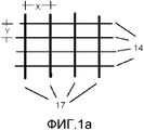
Фиг. 1a схематично показывает группу продольно ориентированных панелей фюзеляжа согласно предыдущему уровню техники, а Фиг. 2a схематично показывает группу панелей, ориентированных по окружности в фюзеляже согласно представленному изобретению.FIG. 1a schematically shows a group of longitudinally oriented fuselage panels according to the prior art, and FIG. 2a schematically shows a group of panels circumferentially oriented in the fuselage according to the present invention.
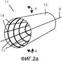
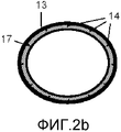
Фиг. 2a и 2b показывают схематичные изображения в перспективе и в поперечном сечении вдоль плоскости A-A фюзеляжа согласно первому варианту осуществления представленного изобретения.FIG. 2a and 2b show schematic perspective and cross-sectional images along the fuselage plane A-A according to the first embodiment of the present invention.
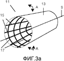
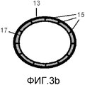
Фиг. 3a и 3b показывают схематичные изображения в перспективе и в поперечном сечении вдоль плоскости A-A фюзеляжа согласно второму варианту осуществления представленного изобретения.FIG. 3a and 3b show schematic perspective and cross-sectional images along the fuselage plane A-A according to a second embodiment of the present invention.
Фиг. 4 представляет собой частичное перспективное изображение внутренней конструкции фюзеляжа согласно первому варианту осуществления представленного изобретения для секции фюзеляжа, отдельными элементами жесткости которого являются стрингеры.FIG. 4 is a partial perspective view of the internal structure of the fuselage according to the first embodiment of the present invention for a fuselage section whose individual stiffeners are stringers.
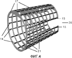
Фиг. 5 представляет собой перспективное изображение внутренней конструкции фюзеляжа согласно второму варианту осуществления представленного изобретения для секции фюзеляжа, отдельными элементами жесткости которого являются балки.FIG. 5 is a perspective view of the internal structure of the fuselage according to the second embodiment of the present invention for a fuselage section whose individual stiffeners are beams.
ПОДРОБНОЕ ОПИСАНИЕ ИЗОБРЕТЕНИЯDETAILED DESCRIPTION OF THE INVENTION
Ориентация панелей фюзеляжа по окружностиOrientation of the fuselage panels in a circle
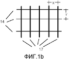
Основная идея представленного изобретения состоит в том, чтобы сконструировать секцию фюзеляжа летательного аппарата таким образом, чтобы его панели были ориентированы по окружности, в противоположность их продольной ориентации в известных фюзеляжах. В них, как проиллюстрировано на Фиг. 1a, расстояние X между шпангоутами 17 больше, чем расстояние Y между стрингерами 14, в то время как в секции фюзеляжа согласно представленному изобретению, проиллюстрированному на Фиг. 1b, расстояние X между шпангоутами 17 меньше, чем расстояние Y между стрингерами 14.The main idea of the presented invention is to construct a section of the fuselage of the aircraft in such a way that its panels are oriented in a circle, in contrast to their longitudinal orientation in known fuselages. In them, as illustrated in FIG. 1a, the distance X between the
В известных фюзеляжах, обычное значение для соотношения X/Y может составлять 2,5, в то время как для фюзеляжей согласно представленному изобретению указанное обычное значение может составлять 0,6.In known fuselages, the usual value for the X / Y ratio can be 2.5, while for the fuselages according to the present invention, the specified normal value can be 0.6.
Первым результатом ориентации панелей по окружности является то, что они получают преимущество изгиба фюзеляжа для противодействия продольным нагрузкам, задерживая начало потери устойчивости. Данное улучшение характеристик панелей после потери устойчивости предоставляет возможность уменьшения массы обшивки.The first circumferential orientation of the panels is that they take advantage of the bending of the fuselage to counter longitudinal loads, delaying the onset of buckling. This improvement in the performance of the panels after loss of stability provides an opportunity to reduce the weight of the skin.
Вторым результатом ориентации панелей по окружности является то, что это облегчает передачу нагрузок по окружности на шпангоуты, следовательно, уменьшая уровень нагрузки по окружности в панелях.The second result of the orientation of the panels around the circumference is that it facilitates the transfer of loads around the circumference to the frames, therefore, reducing the level of load around the circumference in the panels.
Третьим результатом ориентации панелей по окружности является то, что это обеспечивает возможность повышенной прочности конструкции и уменьшения затрат.The third result of the orientation of the panels in a circle is that it provides the possibility of increased structural strength and cost reduction.
Среди прочего, "многошпангоутная" конструкция фюзеляжа согласно представленному изобретению, соответствующая ориентации панелей фюзеляжа по окружности, имеет следующие преимущества:Among other things, the "multi-frame" fuselage structure according to the present invention, corresponding to the circumferential orientation of the fuselage panels, has the following advantages:
Она является более стойкой к повреждению, чем общепризнанная конструкция, так как она имеет больше путей передачи нагрузки.It is more resistant to damage than the generally recognized design, as it has more load transfer paths.
Она особенно подходит для зон с входом локальных нагрузок (Плоскость Вертикального Хвостового Оперения, Пилон и т.д.) потому, что за счет наличия более большого количества шпангоутов, потоки по окружности в обшивке уменьшаются. В дополнение, в зонах, принимающих высокие локальные нагрузки, за счет наличия большего числа шпангоутов, нагрузка на каждый из них уменьшается, так что изготовление каждого из данных шпангоутов из композитных материалов упрощается.It is especially suitable for areas with local loads input (Vertical Tail Plane, Pylon, etc.) because due to the presence of a larger number of frames, the flow around the circumference in the skin is reduced. In addition, in areas receiving high local loads due to the presence of a larger number of frames, the load on each of them is reduced, so that the manufacture of each of these frames from composite materials is simplified.
Данные и другие преимущества будут лучше понятны в двух вариантах осуществления изобретения, которые будут описаны далее.These and other advantages will be better understood in two embodiments of the invention, which will be described later.
Фюзеляж с уменьшенным количеством стрингеровFuselage with a reduced number of stringers
На Фиг. 2a, 2b и 4 можно наблюдать, что в первом варианте осуществления изобретения секция 11 фюзеляжа содержит обшивку 13, которая выполнена с возможностью противодействия продольным, поперечным и преимущественно сдвигающим нагрузкам в плоскости. Стрингеры 14 (в меньшем количестве, чем в случае панелей, ориентированных продольно) используются для получения достаточной изгибающей жесткости обшивки 13, а шпангоуты 17 используются для стабилизации ее против потери устойчивости без увеличения ее толщины, предотвращения общей неустойчивости секции 11 фюзеляжа. Обшивка 13, усиленная стрингерами 14, принимает потоки продольной нагрузки фюзеляжа, в то время как шпангоуты 17 вместе с обшивкой 13 преимущественно выдерживают поперечные нагрузки фюзеляжа и сохраняют аэродинамическую поверхность.In FIG. 2a, 2b and 4, it can be observed that in the first embodiment of the invention, the
И обшивка 13, и стрингеры 14, и шпангоуты 17 изготовлены из композитного материала, которым может быть либо углеродное волокно, либо стекловолокно, встроенное в матрицу термореактивной или термопластичной смолы.And the
Цель состоит в том, чтобы получить более эффективную конструкцию, как в показателях массы, так и стоимости. Вот почему возможным решением изготовления и сборки будет изготовление шпангоутов 17 в виде одной детали (360°), чтобы избежать соединений между различными сегментами, изготовление отдельно обшивки 13 в виде двух или более частей и соединение указанных частей обшивки со шпангоутами 17, получая преимущество более высокой гибкости указанных частей обшивки вследствие того, что они имеют меньшее количество продольных элементов жесткости (стрингеров).The goal is to get a more efficient design, both in terms of mass and cost. That is why a possible solution to the manufacture and assembly would be the manufacture of
Данная конструкция фюзеляжа применима для любого типа поперечного сечения стрингеров (T, омега и т.д.) и любого типа поперечного сечения шпангоутов (C, I, омега и т.д.).This fuselage design is applicable for any type of cross section of stringers (T, omega, etc.) and any type of cross section of frames (C, I, omega, etc.).
Способ изготовления секции 11 фюзеляжа с уже описанной конструкцией тогда включает следующие этапы:A method of manufacturing a
a) предоставляют шпангоуты 17 в виде завершенных деталей,a) provide
b) предоставляют обшивку 13 в виде двух или более частей, с прикрепленными к ней стрингерами 14,b) provide the
с) собирают секцию 11 фюзеляжа посредством соединения указанных частей обшивки 13 со шпангоутами 17.c) the
Тот факт, что внутренняя конструкция фюзеляжа 11 сделана из завершенных шпангоутов 17, устраняет проблемы допусков в стыках между указанными частями обшивки 13, уменьшая возможные отклонения от теоретического аэродинамического профиля. Уменьшение количества стрингеров 14 уменьшает количество пересечений со шпангоутами 17, следовательно, облегчая сборку секции 11 фюзеляжа.The fact that the internal structure of the
Фиг. 4 показывает внутреннюю конструкцию фюзеляжа, которая содержит шпангоуты 17 с двойным T-образным поперечным сечением и стрингеры 14 с T-образным поперечным сечением и большое отверстие 29, выполненное с возможностью приема, например, кессона горизонтального хвостового стабилизатора, короба поддерживающего элемента двигателей или других составных элементов, имеющее две балки 15 в виде рамки для указанного отверстия.FIG. 4 shows the internal structure of the fuselage, which contains frames 17 with a double T-shaped cross section and
В других вариантах осуществления представленного изобретения, шпангоуты 17 и стрингеры 14 могут иметь поперечные сечения с различными формами, например формы C, I или J.In other embodiments of the present invention, the
ФЮЗЕЛЯЖ С БАЛКАМИFUSELAGE WITH BEAMS
Следуя Фиг. 3a, 3b и 5, можно наблюдать, что во втором варианте осуществления изобретения секция 11 фюзеляжа содержит обшивку 13, выполненную с возможностью выдерживать продольные, поперечные и преимущественно сдвигающие нагрузки в плоскости. Балки 15 используются для получения достаточной изгибающей жесткости обшивки 13, а шпангоуты 17 используются для стабилизации ее против потери устойчивости, без увеличения ее толщины, предотвращая общую неустойчивость фюзеляжа 11. Балки 15 вместе с обшивкой 13 принимают преимущественно потоки продольной нагрузки конструкции, в то время как шпангоуты 17 вместе с обшивкой 13 преимущественно выдерживают поперечные нагрузки конструкции и сохраняют аэродинамическую поверхность.Following FIG. 3a, 3b and 5, it can be observed that in the second embodiment of the invention, the
Внутреннюю конструкцию фюзеляжа, сделанного из завершенных шпангоутов 17 и балок 15, изготавливают, как будет видно позже, в виде единой детали для уменьшения насколько возможно соединений между его элементами. Обшивку (изготовленную отдельно в виде двух или более частей) затем приклепывают к внутренней конструкции фюзеляжа, следовательно, значительно упрощая процесс сборки и уменьшая затраты. Это приводит к сильно интегрированной внутренней конструкции фюзеляжа, в которой шпангоуты 17 и балки 15 образуют решетку, конструкция которой является очень эффективной в показателях прочности и жесткости и которая облегчает оптимизацию массы всего фюзеляжа. Подобная сильно интегрированная конструкция, в которой также отсутствуют какие-либо стрингеры, влечет за собой экономию на процессе сборки.The internal structure of the fuselage, made of completed
С данной конструкцией обшивка 13, наряду с балками 15, занимается изгибающими и продольными нагрузками, в то время как шпангоуты 17 предотвращают общую неустойчивость фюзеляжа 11, распределяют и выдерживают вместе с обшивкой 13 нагрузки по окружности и могут иметь вход локальных нагрузок, и, в заключение, решетка, образованная шпангоутами 17 и балками 15, соединенными, где они пересекаются, вместе с обшивкой 13, выдерживают скручивающие нагрузки.With this design, the
В свою очередь, балки 15 также предоставляют опору стенкам шпангоутов 17, что означает, что для предотвращения потери устойчивости указанных стенок не требуются никакие дополнительные элементы жесткости, что уменьшает количество вспомогательных деталей и количество стыков между деталями, следовательно, упрощая способ изготовления.In turn, the
Так как нет никаких стрингеров, в шпангоутах не должно быть никаких "мышиных" отверстий для прохождения через них, поэтому фюзеляж не имеет конструкционных ухудшений, а из процесса изготовления устраняется этап создания данных отверстий.Since there are no stringers, there should not be any “mouse” holes in the frames for passing through them, so the fuselage has no structural impairments, and the stage of creating these holes is eliminated from the manufacturing process.
Внутренняя решетка, которая является результатом соединения шпангоутов 17 и балок 15, представляет собой более стойкую к повреждениям конструкцию, чем обычная конструкция, так, что сталкиваясь с серьезным повреждением в одной части фюзеляжа, остальная часть конструкции способна лучше справляться с требованиями к нагрузкам, не приводя к катастрофе.The internal grill, which is the result of connecting the
И обшивка 13, и балки 15, и шпангоуты 17 изготовлены из композитного материала, которым может быть либо углеродное волокно, либо стекловолокно, погруженное в матрицу термореактивной или термопластичной смолы.And the
Фиг. 5 показывает предпочтительный вариант осуществления представленного изобретения, в котором внутренняя конструкция фюзеляжа включает в себя шпангоуты 17 с омега-образным поперечным сечением и балки 15 с двойным T-образным поперечным сечением.FIG. 5 shows a preferred embodiment of the present invention, in which the internal structure of the fuselage includes
В других вариантах осуществления представленного изобретения шпангоуты 17 и балки 15 могут иметь поперечные сечения с различными формами, такими как формы C, I или J.In other embodiments of the invention, the
Представленное изобретение также относится к способу изготовления секции фюзеляжа с конструкцией, которая была описана, в которой первым этапом является изготовление отдельно внутренней конструкции фюзеляжа и обшивки, а вторым этапом является присоединение обшивки (разделенной, если удобно, на части) к внутренней конструкции фюзеляжа посредством заклепок.The presented invention also relates to a method for manufacturing a fuselage section with the structure that has been described, in which the first step is the manufacture of the internal structure of the fuselage and skin separately, and the second stage is the attachment of the skin (divided, if convenient, into parts) to the internal structure of the fuselage .
Способ изготовления внутренней конструкции фюзеляжа, будь то завершенные секции (360°) или в два или три сектора, основан на помещении заготовок шпангоутов 17 и балок 15, будь то завершенных, либо в виде частей, на оснастку с формой решетки и их совместного отверждения за единственный цикл отверждения или совместного соединения между балками 15 и шпангоутами 17, представленного ранее, либо первым, либо после первого цикла отверждения. В случае шпангоутов 17, сечение которых имеет форму омега (либо любой другой тип замкнутого сечения), как проиллюстрировано на Фиг. 5, должны быть приготовлены некоторые заготовки стабилизирующих ребер шпангоутов 17 в зонах пересечения с балками 15.A method of manufacturing the internal structure of the fuselage, whether it is completed sections (360 °) or in two or three sectors, is based on the placement of blanks of
В случае принятия формы конструкции посредством совместного отверждения, упомянутую выше решетку создают, начиная с отдельных элементов, которые объединяют, начиная с их наслаивания, и которые получают несколько конструктивных функций. Это означает, что получаются все преимущества, которые влечет за собой интегрированная конструкция, с уменьшением также производственных затрат вследствие того, что имеется меньше независимых деталей и что композитные материалы требуют дорогостоящего процесса отверждения, поэтому чем меньше количество независимых деталей, тем требуется меньшее число циклов отверждения, следовательно, уменьшая затраты, а также получая более равномерную передачу нагрузок между составными элементами, которые образуют конструкцию.In the case of the adoption of the form of construction by means of joint curing, the aforementioned lattice is created, starting with individual elements, which combine, starting with their layering, and which receive several structural functions. This means that all the advantages that the integrated design entails are obtained, also with reduced production costs due to the fact that there are fewer independent parts and that composite materials require an expensive curing process, so the less the number of independent parts, the fewer curing cycles are required. therefore, reducing costs, as well as obtaining a more uniform transfer of loads between the constituent elements that form the structure.
Как может хорошо понять квалифицированный специалист, изготовление внутренней конструкции фюзеляжа может потребовать дополнительной технологической оснастки, в зависимости от конкретных форм поперечного сечения балок 15 и шпангоутов 17 для обеспечения правильной передачи и непрерывности нагрузок, где они пересекаются, а также введения "ровницы" (полос равнонаправленных волокон, которые должны быть из такого же материала, что и полоса, используемая в наслаивании, или совместимая) для предотвращения отверстий и обеспечения оптимального совместного отверждения.As a qualified specialist can well understand, the manufacture of the internal structure of the fuselage may require additional technological equipment, depending on the specific cross-sectional shapes of the
В свою очередь, квалифицированному специалисту будет понятно, что подготовка указанных заготовок шпангоутов и балок будет осуществляться с использованием обычных технологий для их наслаивания и принятия ими формы.In turn, a qualified specialist will understand that the preparation of these blanks of frames and beams will be carried out using conventional technologies for layering and taking their form.
Также возможно создать конструкцию, предоставляющую отвержденные шпангоуты 17 и балки 15, будь то в виде завершенных деталей или в виде частей, и соединяя их в зонах их пересечения посредством вторичного соединения или заклепывания.It is also possible to create a structure that provides cured
Что касается изготовления обшивки, удобным считается ее изготовление в виде двух или более частей для облегчения ее соединения с внутренней конструкцией фюзеляжа.As for the manufacture of the skin, it is considered convenient to manufacture it in the form of two or more parts to facilitate its connection with the internal structure of the fuselage.
Несмотря на то, что представленное изобретение было полностью описано в связи с предпочтительными вариантами осуществления, очевидно, что могут быть введены модификации в пределах объема его правовых притязаний, не рассматривая его в виде ограничения данными вариантами осуществления, но содержанием следующей формулы изобретения.Despite the fact that the presented invention has been fully described in connection with the preferred options for implementation, it is obvious that modifications can be made within the scope of its legal claims, without considering it as a limitation of these options for implementation, but the content of the following claims.
Claims (15)
a) предоставляют шпангоуты (17) в виде завершенных деталей;
b) предоставляют обшивку (13) со стрингерами (14), соединенными с ней;
c) собирают секцию (11) фюзеляжа, соединяя обшивку (13) со стрингерами (14) со шпангоутами (17).6. A method of manufacturing a section (11) of the fuselage according to claim 3 in the form of a completed section or in the form of one of its sectors, characterized in the content of the following steps:
a) provide frames (17) in the form of completed parts;
b) provide a skin (13) with stringers (14) connected to it;
c) the fuselage section (11) is assembled by connecting the skin (13) with the stringers (14) with the frames (17).
a) предоставляют внутреннюю конструкцию фюзеляжа, изготовленную из шпангоутов (17) и балок (15);
b) предоставляют обшивку (13);
c) соединяют обшивку (13) с указанной внутренней конструкцией фюзеляжа посредством заклепок.7. A method of manufacturing a section (11) of the fuselage according to claim 5 in the form of a completed section or in the form of one of its sectors, characterized in the content of the following steps:
a) provide the internal structure of the fuselage made of frames (17) and beams (15);
b) provide skin (13);
c) connect the skin (13) with the specified internal structure of the fuselage by rivets.
a1) предоставляют подходящую оснастку;
a2) предоставляют заготовки шпангоутов (17) и балок (15), либо завершенных, либо в виде частей, таким образом, чтобы непрерывные и/или несплошные шпангоуты (17) и/или балки (15) могли принять форму, и помещают их на указанную оснастку;
a3) подвергают внутреннюю конструкцию циклу отверждения.8. A method of manufacturing a fuselage section (11) according to claim 7, characterized in that said step a) is performed by the following sub-steps:
a1) provide suitable equipment;
a2) provide blanks of frames (17) and beams (15), either completed or in the form of parts, so that continuous and / or non-continuous frames (17) and / or beams (15) can take shape, and place them on specified snap-in;
a3) subject the internal structure to a curing cycle.
a1) предоставляют подходящую оснастку;
a2) предоставляют отвержденные шпангоуты (17) и/или балки (15), либо завершенные, либо в виде частей, и помещают их на указанную оснастку;
a3) предоставляют заготовки шпангоутов (17) и/или балок (15), либо завершенных, либо в виде частей, необходимых для принятия формы внутренней конструкции и помещают их на указанную оснастку;
a4) совместное соединение указанных заготовок с указанными отвержденными шпангоутами (17) и/или балками (15) в цикле отверждения.10. A method of manufacturing a section (11) of the fuselage according to claim 7 in the form of a completed section or in the form of one of its sectors, characterized in that said step a) is performed by the following sub-steps:
a1) provide suitable equipment;
a2) provide cured frames (17) and / or beams (15), either completed or in the form of parts, and place them on the specified equipment;
a3) provide blanks for frames (17) and / or beams (15), either completed or in the form of parts necessary to take the form of the internal structure and place them on the specified equipment;
a4) joint connection of these blanks with the specified cured frames (17) and / or beams (15) in the curing cycle.
a1) предоставляют подходящую оснастку;
a2) предоставляют отвержденные шпангоуты (17) и/или балки (15), либо завершенные, либо в виде частей, для принятия формы внутренней конструкции;
a3) соединения шпангоутов (17) и балок (15) в зонах их пересечения посредством вторичного совместного соединения.12. A method of manufacturing a section (11) of the fuselage according to claim 7 in the form of a completed section or in the form of one of its sectors, characterized in that said step a) is performed by the following sub-steps:
a1) provide suitable equipment;
a2) provide cured frames (17) and / or beams (15), either completed or in parts, to take the form of the internal structure;
a3) the connection of frames (17) and beams (15) in the areas of their intersection by means of a secondary joint connection.
a1) предоставляют подходящую оснастку;
a2) предоставляют отвержденные шпангоуты (17) и/или балки (15), либо завершенные, либо в виде частей, для принятия формы внутренней конструкции;
a3) соединяют шпангоуты (17) и балки (15) в зонах их пересечения посредством заклепок.14. A method of manufacturing a section (11) of the fuselage according to claim 7 in the form of a completed section or in the form of one of its sectors, characterized in that said step a) is performed by the following sub-steps:
a1) provide suitable equipment;
a2) provide cured frames (17) and / or beams (15), either completed or in parts, to take the form of the internal structure;
a3) connect the frames (17) and beams (15) in the areas of their intersection by means of rivets.
Applications Claiming Priority (3)
| Application Number | Priority Date | Filing Date | Title |
|---|---|---|---|
| ES201031017A ES2396328B1 (en) | 2010-06-30 | 2010-06-30 | AIRCRAFT FUSELAGE IN COMPOSITE MATERIAL AND PROCEDURES FOR MANUFACTURING. |
| ESP201031017 | 2010-06-30 | ||
| PCT/ES2011/070478 WO2012001207A2 (en) | 2010-06-30 | 2011-06-30 | Aircraft fuselage made out with composite material and manufacturing processes |
Publications (2)
| Publication Number | Publication Date |
|---|---|
| RU2013103823A RU2013103823A (en) | 2014-08-10 |
| RU2564476C2 true RU2564476C2 (en) | 2015-10-10 |
Family
ID=44720025
Family Applications (1)
| Application Number | Title | Priority Date | Filing Date |
|---|---|---|---|
| RU2013103823/11A RU2564476C2 (en) | 2010-06-30 | 2011-06-30 | Aircraft fuselage made of composite and method of its fabrication |
Country Status (7)
| Country | Link |
|---|---|
| US (1) | US20120001023A1 (en) |
| EP (1) | EP2589532A2 (en) |
| CN (1) | CN102958802A (en) |
| CA (1) | CA2804095A1 (en) |
| ES (1) | ES2396328B1 (en) |
| RU (1) | RU2564476C2 (en) |
| WO (1) | WO2012001207A2 (en) |
Families Citing this family (15)
| Publication number | Priority date | Publication date | Assignee | Title |
|---|---|---|---|---|
| EP2634086A1 (en) * | 2012-02-28 | 2013-09-04 | Airbus Operations S.L. | Reinforcing structure integrated in the internal structure of an aircraft of composite material |
| DE102012111128B4 (en) * | 2012-11-19 | 2014-06-26 | Deutsches Zentrum für Luft- und Raumfahrt e.V. | missile |
| EP2774854B1 (en) * | 2013-03-04 | 2017-05-03 | Airbus Defence and Space SA | An improved monolithic fan cowl of an aircraft engine and a manufacturing method thereof |
| EP2889127B1 (en) * | 2013-12-27 | 2020-02-05 | Airbus Operations S.L. | Manufacturing method of a stiffener element |
| EP3040263B1 (en) * | 2014-12-29 | 2017-12-20 | Airbus Operations S.L. | Tail cone of an aircraft |
| EP3040264B1 (en) * | 2014-12-30 | 2018-07-11 | Airbus Operations S.L. | Fuselage rear end of an aircraft |
| CA3001523A1 (en) * | 2015-10-16 | 2017-04-20 | Bombardier Inc. | Stringer-less fuselage structure and method of manufacture |
| DE102016210079A1 (en) * | 2016-06-08 | 2017-12-14 | Airbus Operations Gmbh | Method for producing a body section |
| CN106184697B (en) * | 2016-09-14 | 2019-02-05 | 北京航空航天大学 | A kind of straight line penetrating construction formula composite fuselage construction |
| CN106596003B (en) * | 2016-11-29 | 2019-04-23 | 中国航空工业集团公司沈阳飞机设计研究所 | A kind of composite airplane frame sections pressurising test method |
| US11332228B2 (en) * | 2018-04-06 | 2022-05-17 | Aurora Flight Sciences Corporation | Aircraft fuselage with composite pre-form |
| EP3584053B1 (en) * | 2018-06-19 | 2023-06-07 | Airbus Operations, S.L.U. | Method for manufacturing a rear section of an aircraft and aircraft rear section manufactured by said method |
| CN109739064B (en) * | 2018-12-29 | 2020-04-10 | 中国科学院长春光学精密机械与物理研究所 | Embedded truss and diaphragm integrated structure of space remote sensing camera |
| US11660830B2 (en) * | 2019-01-18 | 2023-05-30 | The Boeing Company | Contoured composite stringers |
| CN112027053A (en) * | 2020-09-10 | 2020-12-04 | 中国航空工业集团公司沈阳飞机设计研究所 | Framework structure of frame beam of middle fuselage of airplane |
Citations (4)
| Publication number | Priority date | Publication date | Assignee | Title |
|---|---|---|---|---|
| EP0444627A1 (en) * | 1990-02-28 | 1991-09-04 | Fuji Jukogyo Kabushiki Kaisha | Aircraft fuselage structure and method of fabricating the same |
| RU2007330C1 (en) * | 1992-02-07 | 1994-02-15 | Самарский государственный аэрокосмический университет | Aircraft baggage compartment |
| SU1777297A1 (en) * | 1990-02-12 | 1997-05-20 | Обнинское научно-производственное объединение "Технология" | Panel of composite material and method for making the same |
| GB2428417A (en) * | 2005-10-27 | 2007-01-31 | Hal Errikos Calamvokis | Aircraft fuselage structure |
Family Cites Families (16)
| Publication number | Priority date | Publication date | Assignee | Title |
|---|---|---|---|---|
| US2389767A (en) * | 1943-09-01 | 1945-11-27 | Budd Edward G Mfg Co | Structural frame |
| US4310132A (en) * | 1978-02-16 | 1982-01-12 | Nasa | Fuselage structure using advanced technology fiber reinforced composites |
| US4828202A (en) * | 1979-09-27 | 1989-05-09 | The Boeing Company | Method and apparatus for wideband vibration damping of reinforced skin structures |
| US5242523A (en) * | 1992-05-14 | 1993-09-07 | The Boeing Company | Caul and method for bonding and curing intricate composite structures |
| JPH10258463A (en) * | 1997-03-19 | 1998-09-29 | Fuji Heavy Ind Ltd | Rib of composite material and forming method thereof |
| US6766984B1 (en) * | 1998-07-16 | 2004-07-27 | Icom Engineering Corporation | Stiffeners for aircraft structural panels |
| JP4318381B2 (en) * | 2000-04-27 | 2009-08-19 | 本田技研工業株式会社 | Manufacturing method of fuselage structure made of fiber reinforced composite material, and fuselage structure manufactured thereby |
| JP4526698B2 (en) * | 2000-12-22 | 2010-08-18 | 富士重工業株式会社 | COMPOSITE MATERIAL AND MANUFACTURING METHOD THEREOF |
| SE519185C2 (en) * | 2001-06-07 | 2003-01-28 | Saab Ab | aircraft Panel |
| US6648273B2 (en) * | 2001-10-30 | 2003-11-18 | The Boeing Company | Light weight and high strength fuselage |
| US7134629B2 (en) * | 2004-04-06 | 2006-11-14 | The Boeing Company | Structural panels for use in aircraft fuselages and other structures |
| US7159822B2 (en) * | 2004-04-06 | 2007-01-09 | The Boeing Company | Structural panels for use in aircraft fuselages and other structures |
| US7503368B2 (en) * | 2004-11-24 | 2009-03-17 | The Boeing Company | Composite sections for aircraft fuselages and other structures, and methods and systems for manufacturing such sections |
| US7410352B2 (en) * | 2005-04-13 | 2008-08-12 | The Boeing Company | Multi-ring system for fuselage barrel formation |
| US8042767B2 (en) * | 2007-09-04 | 2011-10-25 | The Boeing Company | Composite fabric with rigid member structure |
| US7967250B2 (en) * | 2008-05-12 | 2011-06-28 | EMBRAER—Empresa Brasileira de Aeronáutica | Hybrid aircraft fuselage structural components and methods of making same |
-
2010
- 2010-06-30 ES ES201031017A patent/ES2396328B1/en not_active Expired - Fee Related
-
2011
- 2011-05-20 US US13/112,090 patent/US20120001023A1/en not_active Abandoned
- 2011-06-30 CN CN201180032881XA patent/CN102958802A/en active Pending
- 2011-06-30 CA CA2804095A patent/CA2804095A1/en not_active Abandoned
- 2011-06-30 EP EP11763746.2A patent/EP2589532A2/en not_active Withdrawn
- 2011-06-30 RU RU2013103823/11A patent/RU2564476C2/en not_active IP Right Cessation
- 2011-06-30 WO PCT/ES2011/070478 patent/WO2012001207A2/en active Application Filing
Patent Citations (4)
| Publication number | Priority date | Publication date | Assignee | Title |
|---|---|---|---|---|
| SU1777297A1 (en) * | 1990-02-12 | 1997-05-20 | Обнинское научно-производственное объединение "Технология" | Panel of composite material and method for making the same |
| EP0444627A1 (en) * | 1990-02-28 | 1991-09-04 | Fuji Jukogyo Kabushiki Kaisha | Aircraft fuselage structure and method of fabricating the same |
| RU2007330C1 (en) * | 1992-02-07 | 1994-02-15 | Самарский государственный аэрокосмический университет | Aircraft baggage compartment |
| GB2428417A (en) * | 2005-10-27 | 2007-01-31 | Hal Errikos Calamvokis | Aircraft fuselage structure |
Also Published As
| Publication number | Publication date |
|---|---|
| US20120001023A1 (en) | 2012-01-05 |
| ES2396328A1 (en) | 2013-02-20 |
| WO2012001207A2 (en) | 2012-01-05 |
| RU2013103823A (en) | 2014-08-10 |
| CN102958802A (en) | 2013-03-06 |
| ES2396328B1 (en) | 2014-02-06 |
| CA2804095A1 (en) | 2012-01-05 |
| WO2012001207A3 (en) | 2012-07-05 |
| EP2589532A2 (en) | 2013-05-08 |
Similar Documents
| Publication | Publication Date | Title |
|---|---|---|
| RU2564476C2 (en) | Aircraft fuselage made of composite and method of its fabrication | |
| RU2505453C2 (en) | Integral aircraft airframe from composite | |
| US10889363B2 (en) | Efficient sub-structures | |
| AU2013228054B2 (en) | Circumference splice for joining shell structures | |
| US7806367B2 (en) | Integrated multispar torsion box of composite material | |
| RU2573692C2 (en) | Integral aircraft airframe from composite | |
| RU2693141C2 (en) | Panel design and corresponding method | |
| JP2010524770A (en) | Aircraft wing-fuselage assembly | |
| US10940936B2 (en) | Stringer with plank ply and skin construction for aircraft | |
| RU2519111C2 (en) | Structural component and method for structural component manufacturing | |
| US20080179460A1 (en) | Aircraft load frame made of a composite material | |
| RU2435703C2 (en) | Aircraft fuselage structure and manufacturing method | |
| US8899522B2 (en) | Aircraft fuselage with high strength frames | |
| US9592900B2 (en) | Method for the production of a connecting element, connecting element, and aircraft or spacecraft | |
| US20150239207A1 (en) | Composite structural element and torsion box | |
| RU2545218C2 (en) | Aircraft frame and method for its manufacturing | |
| US20130032670A1 (en) | Wall component for an aircraft | |
| CA3010856C (en) | Co-cured spar and stringer center wing box | |
| RU2607894C2 (en) | High loaded aircraft fuselage frame with framed structured wall |
Legal Events
| Date | Code | Title | Description |
|---|---|---|---|
| MM4A | The patent is invalid due to non-payment of fees |
Effective date: 20170701 |