RU2562418C2 - Devices and methods for diagnostics of electronics-based products - Google Patents
Devices and methods for diagnostics of electronics-based products Download PDFInfo
- Publication number
- RU2562418C2 RU2562418C2 RU2013141794/08A RU2013141794A RU2562418C2 RU 2562418 C2 RU2562418 C2 RU 2562418C2 RU 2013141794/08 A RU2013141794/08 A RU 2013141794/08A RU 2013141794 A RU2013141794 A RU 2013141794A RU 2562418 C2 RU2562418 C2 RU 2562418C2
- Authority
- RU
- Russia
- Prior art keywords
- parameter
- electronic product
- parameters
- product
- abnormal
- Prior art date
Links
Images

Classifications
-
- G—PHYSICS
- G05—CONTROLLING; REGULATING
- G05B—CONTROL OR REGULATING SYSTEMS IN GENERAL; FUNCTIONAL ELEMENTS OF SUCH SYSTEMS; MONITORING OR TESTING ARRANGEMENTS FOR SUCH SYSTEMS OR ELEMENTS
- G05B23/00—Testing or monitoring of control systems or parts thereof
- G05B23/02—Electric testing or monitoring
-
- G—PHYSICS
- G05—CONTROLLING; REGULATING
- G05B—CONTROL OR REGULATING SYSTEMS IN GENERAL; FUNCTIONAL ELEMENTS OF SUCH SYSTEMS; MONITORING OR TESTING ARRANGEMENTS FOR SUCH SYSTEMS OR ELEMENTS
- G05B19/00—Programme-control systems
- G05B19/02—Programme-control systems electric
- G05B19/04—Programme control other than numerical control, i.e. in sequence controllers or logic controllers
- G05B19/048—Monitoring; Safety
-
- G—PHYSICS
- G05—CONTROLLING; REGULATING
- G05B—CONTROL OR REGULATING SYSTEMS IN GENERAL; FUNCTIONAL ELEMENTS OF SUCH SYSTEMS; MONITORING OR TESTING ARRANGEMENTS FOR SUCH SYSTEMS OR ELEMENTS
- G05B23/00—Testing or monitoring of control systems or parts thereof
- G05B23/02—Electric testing or monitoring
- G05B23/0205—Electric testing or monitoring by means of a monitoring system capable of detecting and responding to faults
- G05B23/0218—Electric testing or monitoring by means of a monitoring system capable of detecting and responding to faults characterised by the fault detection method dealing with either existing or incipient faults
- G05B23/0243—Electric testing or monitoring by means of a monitoring system capable of detecting and responding to faults characterised by the fault detection method dealing with either existing or incipient faults model based detection method, e.g. first-principles knowledge model
- G05B23/0254—Electric testing or monitoring by means of a monitoring system capable of detecting and responding to faults characterised by the fault detection method dealing with either existing or incipient faults model based detection method, e.g. first-principles knowledge model based on a quantitative model, e.g. mathematical relationships between inputs and outputs; functions: observer, Kalman filter, residual calculation, Neural Networks
-
- Y—GENERAL TAGGING OF NEW TECHNOLOGICAL DEVELOPMENTS; GENERAL TAGGING OF CROSS-SECTIONAL TECHNOLOGIES SPANNING OVER SEVERAL SECTIONS OF THE IPC; TECHNICAL SUBJECTS COVERED BY FORMER USPC CROSS-REFERENCE ART COLLECTIONS [XRACs] AND DIGESTS
- Y02—TECHNOLOGIES OR APPLICATIONS FOR MITIGATION OR ADAPTATION AGAINST CLIMATE CHANGE
- Y02P—CLIMATE CHANGE MITIGATION TECHNOLOGIES IN THE PRODUCTION OR PROCESSING OF GOODS
- Y02P90/00—Enabling technologies with a potential contribution to greenhouse gas [GHG] emissions mitigation
- Y02P90/80—Management or planning
Landscapes
- Physics & Mathematics (AREA)
- Engineering & Computer Science (AREA)
- General Physics & Mathematics (AREA)
- Automation & Control Theory (AREA)
- Artificial Intelligence (AREA)
- Evolutionary Computation (AREA)
- Mathematical Physics (AREA)
- Testing And Monitoring For Control Systems (AREA)
- Testing Or Calibration Of Command Recording Devices (AREA)
Abstract
Description
ОБЛАСТЬ ТЕХНИКИFIELD OF TECHNOLOGY
Данное описание относится к диагностике различных электронных продуктов, развернутых в промышленных установках и процессах.This description relates to the diagnosis of various electronic products deployed in industrial plants and processes.
УРОВЕНЬ ТЕХНИКИBACKGROUND
Мониторинг и диагностика промышленных систем и процессов являются важными событиями, так как изготовители стремятся улучшить качество, расширить производство и снизить издержки. Такой мониторинг обычно нацелен на диагностику неисправностей в различных компонентах производственных систем. Мониторинг производственных систем и их компонентов включает в себя измерение различных переменных окружающей среды, переменных процесса и физических данных, относящихся к компонентам производственных систем. Производственные системы проектируются для применения различных систем мониторинга для мониторинга работы компонентов в пределах этих производственных систем. На основе информации, обеспеченной системами мониторинга, может быть предпринято корректирующее действие для защиты целостности производственных систем, когда один или несколько компонентов производственных систем указывают отказ в их работе.Monitoring and diagnostics of industrial systems and processes are important events, as manufacturers strive to improve quality, expand production and reduce costs. Such monitoring is usually aimed at diagnosing faults in various components of production systems. Monitoring production systems and their components involves measuring various environmental variables, process variables and physical data related to the components of production systems. Production systems are designed to use various monitoring systems to monitor the operation of components within these production systems. Based on the information provided by the monitoring systems, a corrective action can be taken to protect the integrity of production systems when one or more components of production systems indicate a failure in their operation.
Мониторинг современных производственных систем и процессов включает в себя размещение систем внешнего мониторинга, которые измеряют и записывают физические данные и данные окружающей среды, ассоциированные с компонентами производственных систем. Примерная система мониторинга содержит средство считывания, связанное с контролируемыми компонентами для генерации сигналов, которые представляют состояние контролируемых компонентов. Система мониторинга также содержит, по меньшей мере, одну внешнюю станцию управления, которая выполнена с возможностью приема сигналов от одного или нескольких контролируемых компонентов и выполнения диагностики принятых сигналов для идентификации какой-либо неисправности в контролируемых компонентах. Такие примерные системы мониторинга используют отдельные инструменты, которые не могут легко связываться с контролируемыми компонентами, в случае, если контролируемые компоненты являются основанными на электронике продуктами, так как такие инструменты имеют тенденцию вмешательства в нормальное функционирование основанных на электронике продуктов. Кроме того, такие системы мониторинга могут быть дорогостоящими в их реализациях.Monitoring modern production systems and processes includes the placement of external monitoring systems that measure and record the physical and environmental data associated with the components of the production systems. An exemplary monitoring system comprises a reader associated with the monitored components to generate signals that represent the state of the monitored components. The monitoring system also includes at least one external control station, which is configured to receive signals from one or more monitored components and perform diagnostics of the received signals to identify any malfunction in the monitored components. Such exemplary monitoring systems use separate tools that cannot easily communicate with the controlled components if the controlled components are electronic-based products, since such tools tend to interfere with the normal functioning of the electronic-based products. In addition, such monitoring systems can be costly to implement.
Соответственно, из-за риска нарушения производственных процессов, включающих в себя основанные на электронике продукты, вызванного системами внешнего мониторинга, и дорогостоящего внедрения систем внешнего мониторинга, такие системы мониторинга могут быть неподходящими для применения в продуктах, основанных на электронике.Accordingly, due to the risk of disruption of production processes including electronic-based products caused by external monitoring systems and the costly implementation of external monitoring systems, such monitoring systems may not be suitable for use in electronic-based products.
СУЩНОСТЬ ИЗОБРЕТЕНИЯSUMMARY OF THE INVENTION
Нижеследующее представляет собой упрощенную сущность данного раскрытия для обеспечения базового понимания одного или нескольких аспектов данного раскрытия. Эта сущность изобретения не является расширенным представлением данного раскрытия. Она не предназначена ни для идентификации ключевых или основных элементов данного описания, ни для очерчивания объема данного раскрытия. Скорее, единственной целью данной сущности изобретения является представление некоторых концепций данного раскрытия в упрощенной форме в качестве вступления к более подробному раскрытию, которое представлено ниже.The following is a simplified summary of this disclosure to provide a basic understanding of one or more aspects of this disclosure. This summary is not an expanded representation of this disclosure. It is not intended to identify key or basic elements of this description, nor to outline the scope of this disclosure. Rather, the sole purpose of this summary is to present some concepts of this disclosure in a simplified form as a prelude to the more detailed disclosure that is presented below.
Задачей данного раскрытия является обеспечение механизма для выполнения диагностики/анализа в реальном времени неисправностей в электронных продуктах, развернутых в промышленных установках/системах и процессах. Другой задачей данного раскрытия является обеспечение автономных устройств для мониторинга и диагностики электронных продуктов, которые могут быть интегрированы с основанными на электронике продуктами и работают без вмешательства в функционирование электронных продуктов. Другой задачей данного раскрытия является обеспечение превентивного обслуживания электронных продуктов даже перед возникновениями неисправностей в основанных на электронике продуктах. Еще одной задачей данного раскрытия является проверка аутентичности претензий, подаваемых для замены/ремонта электронных продуктов, находящихся под действием гарантийного соглашения.The objective of this disclosure is to provide a mechanism for performing real-time diagnostics / analysis of faults in electronic products deployed in industrial plants / systems and processes. Another objective of this disclosure is to provide stand-alone devices for monitoring and diagnosing electronic products that can be integrated with electronics-based products and operate without interfering with the functioning of electronic products. Another objective of this disclosure is to provide proactive service for electronic products even before the occurrence of malfunctions in electronics-based products. Another objective of this disclosure is to verify the authenticity of claims submitted for the replacement / repair of electronic products subject to a warranty agreement.
Вышеотмеченные и другие задачи могут быть выполнены посредством устройства для диагностики электронного продукта, причем это устройство содержит множество датчиков, связанных в этим электронным продуктом, для мониторинга множества параметров, связанных с этим электронным продуктом, причем каждый датчик выполнен с возможностью генерации, по меньшей мере, одного из аналогового сигнала и цифрового сигнала после мониторинга некоторого параметра; множество конверторов для преобразования аналоговых сигналов, связанных с множеством параметров, в цифровые сигналы; модуль обработки, связанный с этим множеством конверторов для определения аномальных состояний параметров на основе, по меньшей мере, сравнения этих цифровых сигналов с пороговыми значениями параметров, причем каждое аномальное состояние параметра, соответствующее некоторому параметру, определяемое на основе сравнения цифрового сигнала, связанного с этим параметром и пороговым значением параметра, соответствующим этому параметру; память, связанную с этим модулем обработки, причем эта память выполнена с возможностью сохранения аномальных значений параметров; и интерфейс связи для обеспечения аномальных значений параметров, по меньшей мере, для одного внешнего устройства для диагностики этого электронного продукта, где это устройство сконфигурировано в хост-модуле этого электронного продукта. В некотором варианте осуществления, аномальное состояние параметров может быть также определено из одного или нескольких сравнений цифровых сигналов с пороговыми значениями, аномальными градиентами, аномальной комбинацией цифровых сигналов, и вычисленных внутренним образом значений (от множества датчиков, из математической модели и/или аналитического вычисления).The above and other tasks can be performed by means of a device for diagnosing an electronic product, moreover, this device contains many sensors associated in this electronic product, for monitoring a variety of parameters associated with this electronic product, each sensor being configured to generate at least one of the analog signal and the digital signal after monitoring a certain parameter; a plurality of converters for converting analog signals associated with the plurality of parameters into digital signals; a processing module associated with this plurality of converters for determining anomalous state of parameters based on at least comparing these digital signals with threshold parameters, each abnormal state of a parameter corresponding to a certain parameter being determined based on comparing a digital signal associated with this parameter and a threshold value of a parameter corresponding to that parameter; a memory associated with this processing module, and this memory is configured to save anomalous parameter values; and a communication interface for providing anomalous parameter values for at least one external device for diagnosing this electronic product, where this device is configured in the host module of this electronic product. In some embodiment, the abnormal state of the parameters can also be determined from one or more comparisons of digital signals with threshold values, anomalous gradients, an abnormal combination of digital signals, and internally calculated values (from a variety of sensors, from a mathematical model and / or analytical calculation) .
В некотором аспекте, это устройство включает в себя систему обработки, которая является, по меньшей мере, одним из интегральной схемы прикладной ориентации (ASIC), системы на чипе (SOC), блока микроконтроллера (MCU), обработки цифровых сигналов (DSP), электрически программируемого логического устройства (EPLD), комплексного программируемого логического устройства (CPLD), системы дискретных компонентов, гибридных систем и системы программируемых пользователем вентильных матриц (FPGA). Эта система обработки включает в себя один или несколько логических модулей для управления множеством датчиков и множеством конверторов. Этот модуль обработки может быть также сконфигурирован в этой системе обработки, которая может быть воплощена с хост-модуле электронного продукта. В некотором аспекте, этот хост-модуль является, по меньшей мере, одним из монтажной платы электронного продукта, системной платы электронного продукта, центрального процессора (CPU) электронного продукта и модуля ввода/вывода электронного продукта, частично или полностью обеспеченного посредством одной или нескольких частей электронного продукта, единственной платой электронного продукта, основной платой электронного продукта и дочерней платой электронного продукта. В некотором аспекте, память этого устройства выполнена с возможностью сохранения информации, связанной с аномальными состояниями параметров с соответствующей информацией о временной метке.In an aspect, this device includes a processing system that is at least one of an application-oriented integrated circuit (ASIC), a system on a chip (SOC), a microcontroller unit (MCU), digital signal processing (DSP), electrically programmable logic device (EPLD), integrated programmable logic device (CPLD), discrete component systems, hybrid systems and user programmable gate arrays (FPGAs). This processing system includes one or more logic modules for controlling multiple sensors and multiple converters. This processing module may also be configured in this processing system, which may be implemented with the host module of the electronic product. In some aspect, this host module is at least one of an electronic product circuit board, an electronic product system board, an electronic product central processing unit (CPU) and an electronic product input / output module partially or fully provided by one or more parts an electronic product, a single electronic product board, an electronic product core board, and an electronic product daughter board. In an aspect, the memory of this device is configured to store information associated with abnormal states of parameters with corresponding timestamp information.
Преимуществом этого устройства, представляемого в настоящем раскрытии, является точная диагностика параметра, который является причиной неисправности в электронном продукте на основе информации о временной метке. Поскольку аномальные состояния параметров, соответствующие различным параметрам, помечаются по времени, возникновение неисправности в электронном продукте может быть точно связано с одним или несколькими параметрами.The advantage of this device, presented in the present disclosure, is the accurate diagnosis of a parameter that causes a malfunction in an electronic product based on timestamp information. Since the abnormal state of the parameters corresponding to various parameters is marked in time, the occurrence of a malfunction in the electronic product can be precisely associated with one or more parameters.
В одном аспекте, устройство согласно настоящему раскрытию выполнено с возможностью мониторинга разнообразия параметров окружающей среды и рабочих параметров, таких как разность потенциалов между 0 Вольт и потенциалом заземления, мониторинга источника питания, температуры окружающей среды, где размещен данный электронный продукт, ускорений, ударов и вибраций, связанных с компонентами электронного продукта, ударов и вибраций в отсеке, где размещен электронный продукт, источника энергии, подаваемой к электронному продукту, электромагнитных помех в окружающей среде электронного продукта, открывания/закрывания одной или нескольких дверей этого отсека, температуры электронного продукта, влажности в окружающей среде электронного продукта, давления, высоты, угла ориентации по вертикали и горизонтали, локализации относительно Земли, уровня света и яркости, уровня шума, уровня излучений, уровня загрязнения, уровня газов, уровня присутствия дымов и частиц, числа переходов и длительности включения/выключения источника питания, и логических входов для мониторинга одного или нескольких объектов, помещенных в окрестности электронного продукта.In one aspect, a device according to the present disclosure is configured to monitor a variety of environmental and operating parameters, such as a potential difference between 0 Volts and ground potential, monitoring a power source, the ambient temperature of the electronic product, accelerations, shock and vibration related to the components of the electronic product, shock and vibration in the compartment where the electronic product is located, the source of energy supplied to the electronic product, electromagnets interference in the environment of the electronic product, opening / closing one or more doors of this compartment, temperature of the electronic product, humidity in the environment of the electronic product, pressure, height, vertical and horizontal orientation angle, localization relative to the Earth, light level and brightness, level noise, radiation level, pollution level, gas level, the presence of fumes and particles, the number of transitions and the duration of the on / off power supply, and logic inputs for monitoring one or how many objects placed in the vicinity of the electronic product.
В другом аспекте, описанное устройство выполнено с возможностью передачи аномальных состояний параметров к части электронного продукта (такой как центральный процессор (CPU) электронного продукта и связанные с ним средства связи) или к внешнему устройству, такому как устройство связи инженеров обслуживания и локальная станция (например, ключ универсальной последовательной шины (USB), USB диск, персональный компьютер (PC), планшетный компьютер, смартфон и/или карманный терминал) или центральная станция управления для достижения преимущества обслуживания планирования или проведения превентивного обслуживания электронного продукта.In another aspect, the described device is configured to transmit abnormal states of parameters to a portion of an electronic product (such as a central product electronic processor and associated communications equipment) or to an external device, such as a communication device of service engineers and a local station (e.g. , universal serial bus (USB) key, USB disk, personal computer (PC), tablet computer, smartphone and / or handheld terminal) or central control station to achieve an advantage o Serviceability of planning or carrying out preventive maintenance of electronic product.
В другом аспекте, модуль обработки описанного устройства дополнительно выполнен с возможностью вычисления временной длительности, связанной с этими параметрами и вычисления числа появлений, по меньшей мере, одного параметра для достижения преимущества точного сохранения информации, связанной с аномальными состояниями параметров, что позволяет осуществить точную диагностику неисправностей в основанных на электронике продуктах. Этот модуль обработки дополнительно выполнен с возможностью вычисления математического моделирования, связанного с некоторым параметром на основе, по меньшей мере, одного из временной длительности, связанной с этим параметром, числа появлений этого параметра и исторической информации, связанной с этим параметром. Этот модуль обработки дополнительно выполнен с возможностью определения аномального состояния параметров на основе, по меньшей мере, одного из сравнения цифровых сигналов с пороговыми значениями параметров, временной длительности, связанной с этим параметром, числа появлений этого параметра и математического моделирования.In another aspect, the processing module of the described device is further configured to calculate the time duration associated with these parameters and calculate the number of occurrences of at least one parameter to achieve the advantage of accurately storing information related to the abnormal conditions of the parameters, which allows for accurate troubleshooting in electronics-based products. This processing module is further configured to calculate mathematical modeling associated with a parameter based on at least one of the time duration associated with this parameter, the number of occurrences of this parameter, and historical information associated with this parameter. This processing module is further configured to determine the anomalous state of the parameters based on at least one of a comparison of digital signals with threshold values of the parameters, the time duration associated with this parameter, the number of occurrences of this parameter, and mathematical modeling.
Вышеотмеченные и другие задачи также достигаются посредством способа, выполняемого в устройстве для диагностики электронного продукта, причем этот способ предусматривает: считывание множества параметров, связанных с этим электронным продуктом, где считывание некоторого параметра выполняется для генерирования, по меньшей мере, одного из аналогового сигнала и цифрового сигнала, связанного с этим параметром; преобразование аналоговых сигналов, связанных с множеством параметров в цифровые сигналы; определение аномальных состояний параметров, связанных с этим множеством параметров на основе, по меньшей мере, сравнения каждого цифрового сигнала, связанного с некоторым параметром, с пороговым значением параметра, соответствующим этому параметру; и сохранение информации, связанной с аномальными состояниями параметров, соответствующих этому множеству параметров; это устройство сконфигурировано в хост-модуле этого электронного продукта. Этот способ дополнительно включает в себя передачу информации, связанной с аномальными состояниями параметров, по меньшей мере, к одному внешнему устройству для диагностики одной или нескольких неисправностей в этом электронном продукте.The above and other tasks are also achieved by a method performed in a device for diagnosing an electronic product, the method comprising: reading a plurality of parameters associated with this electronic product, where a certain parameter is read to generate at least one of an analog signal and a digital the signal associated with this parameter; conversion of analog signals associated with a variety of parameters into digital signals; determination of the anomalous states of the parameters associated with this set of parameters based on at least a comparison of each digital signal associated with a certain parameter with a threshold parameter value corresponding to this parameter; and storing information associated with abnormal states of the parameters corresponding to this set of parameters; this device is configured in the host module of this electronic product. This method further includes transmitting information related to abnormal states of the parameters to at least one external device for diagnosing one or more malfunctions in this electronic product.
Выгодным образом, технической целью различных вариантов осуществления этих устройств и способов является диагностика неисправностей в основанных на электронике продуктах (развернутых в промышленных системах и процессах), вызываемых внешним вмешательством, нарушениями, условиями внешней среды и нерасчетными рабочими условиями, рабочим профилем/циклированием и профилем назначения, связанным с основанными на электронике продуктами. Описанные устройства и способы обеспечивают диагностику отказа, сбоев в основанных на электронике продуктах и способствуют упреждению превентивного обслуживания для электронных продуктов. Некоторые варианты осуществления выполнены с возможностью сохранения информации о внешних вмешательствах, сбоях, условиях внешней среды вместе с соответствующей временной меткой, что позволяет бригаде поддержки/обслуживания реализовать правильный уровень диагностики неисправностей и реализовать в более короткое время соответствующее действие обслуживания, которое должно быть предпринято. Различные варианты осуществления этих устройств и способов выполнены с возможностью сохранения уместной информации, если данный продукт был использован при нерасчетных/специфических рабочих условиях, и такая информация может использоваться для принятия решения об аутентичности претензий, подаваемых для замены/ремонта электронных продуктов, находящихся под действием гарантийного соглашения. Далее, эти устройства и способы способны к интеграции/работе в основанных на электронике продуктах без вызывания какого-либо вмешательства в функции электронных продуктов.Advantageously, the technical goal of the various embodiments of these devices and methods is to diagnose malfunctions in electronics-based products (deployed in industrial systems and processes) caused by external interference, disturbances, environmental conditions and off-design operating conditions, operating profile / cycling and destination profile related to electronics-based products. The described devices and methods provide diagnostics of failure, failures in electronics-based products and contribute to anticipatory preventive maintenance for electronic products. Some embodiments are configured to store information about external interventions, failures, environmental conditions together with an appropriate time stamp, which allows the support / service team to implement the correct level of troubleshooting and to implement the corresponding service action to be taken in a shorter time. Various embodiments of these devices and methods are configured to store relevant information if the product was used under off-design / specific operating conditions, and such information can be used to decide on the authenticity of claims submitted for replacement / repair of electronic products under warranty agreement. Further, these devices and methods are capable of integration / operation in electronics-based products without causing any interference with the functions of electronic products.
Дополнительные задачи, преимущества и особенности данного описания явствуют из следующего подробного описания и формулы изобретения.Additional objectives, advantages and features of this description will be apparent from the following detailed description and claims.
КРАТКОЕ ОПИСАНИЕ ЧЕРТЕЖЕЙBRIEF DESCRIPTION OF THE DRAWINGS
Для более полного понимания примерных вариантов осуществления данного описания, далее приводится последующее описание со ссылкам на чертежами, на которых:For a more complete understanding of exemplary embodiments of this description, the following description is given with reference to the drawings, in which:
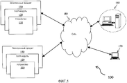
Фиг. 1 иллюстрирует окружение, представляющее основанные на электронике продукты, устройства для диагностики неисправностей в этих основанных на электронике продуктах и внешние устройства, в соответствии с примерным вариантом осуществления данного описания;FIG. 1 illustrates an environment representing electronics-based products, devices for diagnosing faults in these electronics-based products, and external devices, in accordance with an exemplary embodiment of this description;
Фиг. 2 иллюстрирует представление при помощи блок-схемы устройства для диагностики неисправностей в электронном продукте, в соответствии с примерным вариантом осуществления данного описания;FIG. 2 illustrates a block diagram representation of a device for diagnosing faults in an electronic product, in accordance with an exemplary embodiment of this description;
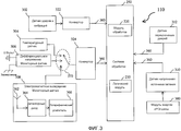
Фиг. 3 иллюстрирует представление при помощи блок-схемы реализации этого устройства, в соответствии с примерным вариантом осуществления данного описания; иFIG. 3 illustrates a representation using a block diagram of an implementation of this device, in accordance with an exemplary embodiment of the present description; and
Фиг. 4 является блок-схемой, изображающей примерный способ для мониторинга и диагностики электронного продукта, в соответствии с примерным вариантом осуществления данного описания.FIG. 4 is a flowchart depicting an example method for monitoring and diagnosing an electronic product, in accordance with an example embodiment of this description.
ОСУЩЕСТВЛЕНИЕ ИЗОБРЕТЕНИЯDETAILED DESCRIPTION OF THE INVENTION
В следующем описании, с целями объяснения, изложены многочисленные конкретные подробности для обеспечения глубокого понимания данного описания. Однако для специалиста в данной области техники будет ясно, что данное описание может практиковаться без этих конкретных подробностей. В других случаях, структуры и устройства показаны только в форме блок-схем, во избежание затемнения данного описания.In the following description, for purposes of explanation, numerous specific details are set forth in order to provide a thorough understanding of this description. However, it will be clear to a person skilled in the art that this description may be practiced without these specific details. In other cases, structures and devices are shown only in block diagram form in order to avoid obscuring this description.
Ссылка в этой спецификации на «один вариант осуществления» или «некоторый вариант осуществления» означает, что некоторая конкретная особенность, структура или характеристика, описанная в соединении с этим вариантом осуществления, включена, по меньшей мере, в один вариант осуществления данного описания. Появления фразы «в одном варианте осуществления» в различных местах в этой спецификации необязательно все ссылаются на один и тот же вариант осуществления, а также не являются отдельными или альтернативными вариантами осуществления, взаимно исключающими другие варианты осуществления. Кроме того, описываются различные особенности, которые могут быть проявлены некоторыми вариантами осуществления, а не другими. Аналогично, описываются различные требования, которые могут быть требованиями для некоторых вариантов осуществления, но не для других.Reference in this specification to “one embodiment” or “some embodiment” means that some specific feature, structure, or characteristic described in connection with this embodiment is included in at least one embodiment of this description. Appearances of the phrase “in one embodiment” at various places in this specification are not necessarily all referring to the same embodiment, nor are they separate or alternative embodiments mutually exclusive of other embodiments. In addition, various features are described that may be exhibited by some embodiments, rather than others. Similarly, various requirements are described, which may be requirements for some embodiments, but not for others.
Кроме того, хотя следующее описание содержит много специфики для целей иллюстрации, специалисту в данной области техники будет ясно, что много вариаций и/или изменений упомянутых подробностей находятся в пределах объема данного описания. Аналогично, хотя многие из особенностей данного описания описываются в терминах друг друга, или в сопряжении друг с другом, специалисту в данной области техники будет ясно, что многие из этих особенностей могут быть обеспечены независимо от других особенностей. Соответственно, это описание данного изобретения изложено без какой-либо потери общности для данного описания и без наложения ограничений на данное описание.In addition, although the following description contains a lot of specificity for purposes of illustration, it will be clear to a person skilled in the art that many variations and / or changes to the details mentioned are within the scope of this description. Similarly, although many of the features of this description are described in terms of each other, or in conjunction with each other, it will be clear to a person skilled in the art that many of these features can be provided independently of other features. Accordingly, this description of the present invention is set forth without any loss of generality for this description and without imposing restrictions on this description.
В широком смысле, варианты осуществления данного описания раскрывают устройства и способы для диагностики неисправностей в основанных на электронике продуктах, используемых в производственных системах и процессах. Эти устройства и способы обеспечивают механизм для мониторинга и сохранения информации о внешних вмешательствах, сбоях, условиях внешней среды, рабочем профиле/циклировании и профиле назначения, связанными с основанными на электронике продуктами. Различные варианты осуществления этих устройств и способов дополнительно способны к диагностике отказа, сбоев в основанных на электронике продуктах и способствуют упреждению превентивного обслуживания для этих электронных продуктов. Например, эти устройства и способы способны обеспечить мгновенный доступ к информации, ассоциированной с непрерывным мониторингом электронных продуктов для помощи в идентификации неисправностей в этих основанных на электронике продуктах даже перед возникновением неисправностей в основанных на электронике продуктах. Некоторые варианты осуществления выполнены с возможностью сохранения информации о внешних вмешательствах, сбоях, условиях внешней среды, рабочем профиле/циклировании и профиле назначения вместе с соответствующей временной меткой для осуществления возможности реализации бригадой поддержки/обслуживания правильного уровня диагностики и реализации в более короткое время соответствующего действия обслуживания, которое должно быть предпринято. Различные варианты осуществления этих устройств и способов обеспечивают механизм для сохранения уместной информации, если данный продукт использовался в нерасчетных/определенных рабочих условиях, и то же самое может использоваться для аутентификации претензий, подаваемых для замены продуктов, находящихся под действием гарантийного соглашения.In a broad sense, embodiments of this description disclose devices and methods for diagnosing faults in electronics-based products used in manufacturing systems and processes. These devices and methods provide a mechanism for monitoring and storing information about external interventions, failures, environmental conditions, work profile / cycling and destination profile associated with electronics-based products. Various embodiments of these devices and methods are further capable of diagnosing failure, failures in electronics-based products, and contribute to proactive preventive maintenance for these electronic products. For example, these devices and methods are capable of providing instant access to information associated with the continuous monitoring of electronic products to help identify malfunctions in these electronic-based products even before the occurrence of malfunctions in electronic-based products. Some embodiments are configured to store information about external interventions, failures, environmental conditions, work / cycling and destination profiles, together with an appropriate time stamp to enable the support / service team to implement the correct level of diagnostics and implement the corresponding maintenance action in a shorter time to be undertaken. The various embodiments of these devices and methods provide a mechanism for storing relevant information if the product has been used in off-design / specified operating conditions, and the same can be used to authenticate claims submitted to replace products under warranty.
Фиг. 1 иллюстрирует окружение 100, включающее основанные на электронике продукты, устройства для диагностики электронных продуктов и внешние устройства, в соответствии с некоторым вариантом осуществления. Окружение 100 представляет устройства 110, связанные с основанными на электронике продуктами 150. Устройство 110 связано с электронным продуктом 150 и выполнено с возможностью мониторинга множества параметров, связанных с данными окружения/внешней среды, рабочими данными и переменными процессов, связанных с продуктом 150. Устройство 110 также выполнено с возможностью облегчения диагностики неисправностей в продукте 150 на основе контролируемых параметров и выполнено с возможностью облегчения планирования превентивного обслуживания продукта 150 на основе этих контролируемых параметров. Здесь, термин «неисправность» относится к любому состоянию продукта 150, которое включает в себя любой вид отказа, рисков, сбоя или дефекта в продукте 150, которые могут препятствовать нормальному функционированию продукта 150, или состоянию, в котором продукт 150 может не быть безопасным при работе. Термин «неисправность» используется по всему описанию (равнозначно с другими эквивалентными терминами) в ссылке на вышеотмеченные состояния продукта 150.FIG. 1 illustrates an
Устройство 110 может быть сконфигурировано или воплощено в хост-модуле 120 в продукте 150. Примером хост-модуля 120 может быть печатная плата (PCB), которая может быть тесно связана или встроена в продукт 150. Например, в некоторых вариантах осуществления, хост-PCB может быть воплощена в одном из монтажной платы продукта 150, системной платы продукта 150, центрального процессора (CPU) продукта 150 или модуля ввода/вывода (I/O) продукта 150. Примеры монтажной платы продукта 150 могут включать в себя специализированную плату продукта 150, единственную плату, такую как основная плата или дочерняя плата продукта 150.The
Примерами продукта 150 могут быть статический электронный продукт, электронный продукт, размещенный в некотором устройстве в движении, или электронные компоненты, помещенные в платы, каркасы, коробки, камеры и т.п. Например, электронные продукты, такие как контроллеры, компьютеры, шлюзы, регуляторы, электронные системы мониторинга и диагностики, системы электронной защиты, электронные реле, электронные системы электропитания, системы передачи, системы измерения и т.п., которые используются в любом промышленном предприятии, на фабрике, в оборудовании или нефтеперегонном заводе, могут быть примерами продукта 150. Более конкретно, продуктом 150 может быть электронный продукт, используемый в различных промышленных областях, неисчерпывающим образом включающие в себя энергетические предприятия, сеть, транспорт, заводы горной промышленности, заводы, связанные с нефтехимическими производственными применениями, руда, топливо, бумага, продукты сельского хозяйства, механика, авионика и т.п. Некоторые примеры электронных продуктов в области предприятий энергетики (для типов топлива, таких как гидроэлектроэнергия, ядерное, тепловое, возобновляемое, отходы и т.п.) могут включать в себя распределенные системы управления (DCS), контроллеры, регуляторы, продукты мониторинга и диагностики и электронные продукты электропитания. Далее, некоторые примеры электронных продуктов в этой сети могут включать в себя инспекционный контроль и сбор данных (SCADA), контроллеры, электронные реле, продукты защиты, продукты измерений и продукты связи. Далее, некоторые примеры компонентов в транспортной области могут включать в себя продукты сигнализации (статические), продукты прокатного стана и продукты метро.Examples of the
Устройство 110 коммуникативно связано, постоянно или время от времени (например, после того, как в продукте 150 детектирована неисправность), с локальной или центральной станцией 160 управления или одним или несколькими устройствами 170 связи инженера(ов) или техника(ов) обслуживания, через сеть 180. Станцией 160 управления может быть локальная или центральная станция управления. Станция 160 управления и устройство 170 связи могут быть способны к приему и посылке информации о контролируемых параметрах при помощи устройств 110. Примеры сети 180 могут включать в себя проводные сети, фиксированный или съемный кабель, беспроводные сети или их комбинации (например, Интернет). Примеры проводных сетей могут включать в себя Ethernet, локальную вычислительную сеть (LAN) и т.п. Примеры беспроводной сети могут включать в себя сеть Wi-Fi, сотовую сеть, беспроводные LAN и т.п.The
Устройство 110 выполнено с возможностью мониторинга и диагностики различных параметров, относящихся к продукту 150. Пример этих параметров может включать в себя параметры окружения/окружающей среды, где размещен продукт 150, рабочие параметры, связанные с продуктом 150, и переменную процесса, связанную с продуктом 150. Параметры, относящиеся к продукту 150, могут быть связаны со всем продуктом 150 или различными компонентами продукта 150. Некоторые неисчерпывающие примеры этих параметров обеспечены ниже и контролируются устройством 110:The
1. Разность потенциалов между 0 Вольт (В) и потенциалом заземления1. Potential difference between 0 Volt (V) and ground potential
2. Температура окружающей среды, где размещен продукт 1502. The ambient temperature where the product is placed 150
3. Ускорения, удары и вибрации, связанные с компонентами продукта 150, которые являются статичными или находятся в движении3. Acceleration, shock, and vibration associated with
4. Удары и вибрация на отсеке, где размещен продукт 1504. Shocks and vibration in the compartment where the product is located 150
5. Источник энергии, подаваемой к продукту 1505. The source of energy supplied to the
6. Электромагнитные помехи в окружении продукта 1506. Electromagnetic interference in the environment of the
7. Открывание/закрывание одной или нескольких дверец отсека или коробки, где размещен продукт 1507. Opening / closing one or more doors of the compartment or box where the product is located 150
8. Температура продукта 1508.
9. Влажность в окружающей среде9. Humidity in the environment
10. Давление10. Pressure
11. Высота11. Height
12. Угол ориентации по вертикали и горизонтали12. The angle of orientation vertically and horizontally
13. Локализация относительно Земли13. Location relative to the Earth
14. Уровень света и яркости14. The level of light and brightness
16. Уровень излучений, например, альфа, бета, гамма и т.п.16. Emission level, for example, alpha, beta, gamma, etc.
17. Уровень загрязнения17. The level of pollution
18. Уровень присутствия газов в окружающей среде18. The level of gas in the environment
19. Уровень присутствия дымов и частиц в окружающей среде19. The level of presence of fumes and particles in the environment
20. Число переходов и длительность включения/выключения источника питания20. The number of transitions and the duration of the on / off power supply
21. Логические вводы для мониторинга одного или нескольких объектов, помещенных в окрестности продукта 15021. Logic inputs for monitoring one or more objects located in the vicinity of the
22. Независимая система наблюдения.22. Independent surveillance system.
Устройство 110 выполнено с возможностью диагностики отказа в продукте 150 на основе контролируемых параметров и выполнено с возможностью поддержки претензий клиента для замены/ремонта устройства 110, находящегося под действием гарантийного соглашения. Устройство 110 дополнительно выполнено с возможностью обеспечения упреждения и планирования превентивного обслуживания или обеспечения рекомендаций, касающихся рабочих условий для пользователя продукта 150. Они дополнительно объясняются в ссылке на фиг. 2 и 3.The
На фиг. 2 показана блок-схема устройства (такого как устройство 110) для диагностики электронного продукта (такого как продукт 150) в соответствии с некоторым вариантом осуществления данного описания. Устройство 110 включает в себя множество датчиков 210 (например, датчик 1, датчик 2, …, датчик n) для мониторинга параметров (обеспеченных в ссылке на фиг. 1), связанных с продуктом 150. Некоторыми примерами датчиков 210 могут быть аналоговые датчики, тогда как некоторыми примерами датчиков 210 могут быть цифровые датчики. Обычно, аналоговые датчики используются для мониторинга большинства параметров. Однако, в некоторых примерах, для мониторинга параметров, таких как то, закрыты ли дверцы отсека (где размещен продукт 150) или нет, может быть использован цифровой датчик. Кроме того, некоторые параметры, такие как влажность, давление, высота, уровень света/яркости, уровень шума, могут контролироваться любым из цифрового или аналогового датчиков. Здесь, термин «мониторинг» параметров относится к считыванию, детектированию или измерению параметров при различных частотах выборки для генерации аналогового или цифрового сигналов, которые соответствуют состоянию, условиям или значению, связанным с этими параметрами, и первичной целью мониторинга является генерация сигнала, который соответствует состоянию, условиям или значению, связанному с этим конкретным параметром.In FIG. 2 shows a block diagram of a device (such as device 110) for diagnosing an electronic product (such as product 150) in accordance with some embodiment of this description. The
Датчики 210 могут быть сконфигурированы таким образом, что они выполняют либо периодический, либо непрерывный мониторинг некоторого параметра. Например, параметр, который изменяется (или эволюционирует) с большей скоростью, может контролироваться непрерывно, тогда как параметр, изменяющийся с относительно более низкой скоростью, может контролироваться периодически (с интервалами). Примеры параметров, которые требуют непрерывного измерения, могут включать в себя, но не ограничены этим, источник энергии, подаваемой к продукту 150; ускорения, удары и вибрации; детектирование открывания/закрывания дверец отсека; электромагнитные нарушения/помехи/возмущения; и т.п. Примеры параметров, которые требуют периодических измерений, могут включать в себя, но не ограничены этим, температуру, влажность, давление и т.п. Однако, подсистема I/O (ввода/вывода) устройства 110, производительность вычислений и емкость информационной памяти устройства 110 может также определять то, как часто может контролироваться некоторый параметр.Sensors 210 may be configured to perform either periodic or continuous monitoring of a parameter. For example, a parameter that changes (or evolves) with greater speed can be monitored continuously, while a parameter that changes with a relatively lower speed can be monitored periodically (at intervals). Examples of parameters that require continuous measurement may include, but are not limited to, a source of energy supplied to the
Устройство 110 включает в себя конверторы 215 для преобразования аналоговых сигналов, генерируемых датчиками 210, в цифровые сигналы. В некотором примере, эти конверторы могут быть аналого-цифровыми преобразователями (ADC). Могут быть множественные конверторы 215, которые соответствуют соответствующим им датчикам 210 и связаны с соответствующими датчиками 210 для преобразования аналоговых сигналов (принятых от соответствующих аналоговых датчиков 210) в цифровые сигналы. Следует отметить, что некоторые параметры могут контролироваться цифровыми датчиками (например, датчиком N), и конвертор 215 не будет необходим в таких случаях. В некоторых примерах, некоторые параметры не требуется контролировать непрерывным образом (скорее, эти параметры контролируются периодическим образом), единственный конвертор 215 может быть достаточным для преобразования аналоговых сигналов, принятых такими множественными датчиками, в цифровые сигналы. В таких примерах, переключатель или мультиплексор может использоваться для приема сигналов от множественных датчиков и обеспечить их вывод для конвертора 215. Следует понимать, что посредством использования переключателя или мультиплексора, число требуемых конверторов, таких как ADC, снижается. Например, конвертор 215 может быть выполнен с возможностью приема аналоговых сигналов от множественных датчиков 210 способом мультиплексирования с разделением времени и затем может преобразовать аналоговые сигналы в цифровые сигналы. Например, как показано на фиг. 2, датчики 2, 3 и 4 связаны с единственным конвертором 215. Такое связывание множественных датчиков с единственным конвертором 215 дополнительно объясняется в ссылке на фиг. 3.The
В некотором варианте осуществления, устройство 110 выполнено с возможностью определения аномальных состояний параметров, соответствующих этим параметрам, на основе цифровых сигналов (или значений), принятых от конверторов 215 или датчиков 210. Устройство 110 может включать в себя модуль обработки 220 для определения аномальных состояний параметров. Это модуль 220 обработки может иметь внутреннюю или сопутствующую память для хранения команд, которые могут выполняться этим модулем 220 обработки, и для сохранения информации, связанной с аномальными состояниями параметров. Модуль 220 обработки может быть сконфигурирован в системе обработки 250. Системой обработки 220 может быть интегральная схема прикладной ориентации (ASIC), система на чипе (SOC), блок микроконтроллеров (MCU), обработка цифровых сигналов (DSP), электрически программируемое логическое устройство (EPLD), комплексное программируемое логическое устройство (CPLD), система дискретных компонентов, гибридные системы и система программируемых пользователем вентильных матриц (FPGA). В некотором варианте осуществления, система обработки 220 может быть воплощена в хост-системе, такой как хост-система 120 продукта 150.In some embodiment,
Модуль 220 обработки выполнен с возможностью определения аномальных состояний параметров на основе, по меньшей мере, сравнения цифровых сигналов (значений параметров) с множеством пороговых значений параметров. В некотором примере, каждый параметр может иметь одно или несколько пороговых значений параметра, например, минимальное определенное значение этого параметра и максимальное определенное значение этого параметра. В некотором примере, если цифровой сигнал, связанный с некоторым параметром, таким как температура окружающей среды, представляет температуру окружающей среды в 392°F, и если пороговое значение параметра для температуры окружающей среды равно 280°F, то измерение 392°F определяется как аномальное значение параметра, и, следовательно, аномальное значение параметра также определяется. Аналогично, другие цифровые сигналы, связанные с различными параметрами, сравниваются с их соответствующими пороговыми значениями параметров для определения аномальных состояний параметров, непрерывным образом. В некоторых примерах, пороговое значение параметра может также включать в себя предварительно заданным градиент. В таких примерах, градиент значений измерения (цифровых значений) для некоторого параметра сравнивается с предварительно заданным градиентом, соответствующим этому параметру, для определения аномального состояния параметра, соответствующего этому параметру.
В некоторых вариантах осуществления, модуль 220 обработки выполнен с возможностью определения аномальных состояний параметров на основе какой-либо комбинации значений параметров (цифровых сигналов), обеспеченных датчиками 210 и/или конверторами 215, и математического анализа и/или моделирования на основе контролируемой информации, связанной с параметрами. Например, модуль 220 обработки может быть выполнен с возможностью вычисления аномального состояния параметра для некоторого параметра на основе временной длительности, связанной с этим параметром; числом появлений этого параметра; и математического моделирования и/или анализа, относящегося к этой временной длительности, числу появлений и сравнения временной длительности и числа появлений в соответствующими историческими архивными данными. Модуль 220 обработки может быть выполнен с возможностью вычисления временной длительности, для которой некоторый параметр непрерывно контролировался как имеющий аномальные значения параметра. В некотором примере, модуль 220 обработки может вычислить временную длительность, для которой некоторый параметр (такой как температура окружающей среды) оставался более высоким, чем некоторое пороговое значение параметра (оптимальная температура), и если определено, что температура окружающей среды оставалась более высокой, чем оптимальная температура в течение периода, большего, чем некоторая пороговая длительность, то для параметра температуры окружающей среды может быть определено аномальное состояние параметра. В другом примере, модуль 220 обработки может вычислить временную длительность, в течение которой продукт 150 находился в непрерывном состоянии включения, и если продукт 150 был в непрерывном состоянии включения дольше, чем некоторый пороговый период времени, то может быть определено аномальное состояние параметра.In some embodiments, the
Далее, модуль 220 обработки может быть также выполнен с возможностью подсчета числа появлений для некоторых параметров. Например, модуль 220 обработки может подсчитать количество переходов «включено/выключено» источника энергии, подаваемой к продукту 150, во время некоторого периода времени. В некоторых примерах, модуль 220 обработки может подсчитать число появлений на всем сроке службы продукта 150. Кроме того, модуль 220 обработки выполнен с возможностью вычисления накопленных появлений аномального состояния, соответствующего некоторому параметру, или общей длительности появления аномального состояния на сроке службы продукта, и такая вычислительная информация может быть сохранена в модуле 225 памяти.Further, the
Соответственно, здесь следует понимать, что «аномальное состояние параметра» может включать в себя условия/состояния, когда аномальное состояние параметра определяется соответствующим некоторому параметру устройством 110. В некоторых примерах, «аномальное состояние параметра» может включать в себя условия/состояния, когда аномальное значение параметра определяется в течение некоторого непрерывного периода времени. В некоторых дополнительных примерах, «аномальное состояние параметра» может включать в себя условия/состояния, когда число появлений аномального состояния параметра превышает пороговое число. В некоторых примерах, «аномальное состояние параметра» может включать в себя комбинацию условий/состояний, связанных с определением аномального значения параметра, определением аномального значения параметра для некоторого непрерывного периода времени и/или числа появлений аномального значения параметра, превышающего это пороговое число. Далее, модуль 220 обработки может быть выполнен с возможностью выполнения некоторых математических операций, моделирования и/или анализа на основе аномальных значений параметра, временных длительностей, связанных с аномальными значениями параметра, числа появлений, связанных с аномальными значениями параметра, и архивных исторических данных, относящихся к соответствующим параметрам. На основе таких математических операций, моделирования и/или анализа, в некоторых вариантах осуществления могут быть определены аномальные значения параметров.Accordingly, it should be understood here that the “abnormal state of the parameter” can include conditions / states when the abnormal state of the parameter is determined by
Модуль 220 обработки может быть воплощен некоторым количеством различных способов. Модуль 220 обработки может быть воплощен как одно или несколько различных средств обработки в системе обработки 250. Примеры средства обработки могут включать в себя сопроцессор, микропроцессор, дискретные компоненты, микроконтроллер, процессор цифровых сигналов (DSP), схемы обработки с сопутствующим DSP или без него, или различные другие устройства обработки, включающие в себя интегральные схемы, такие как ASIC, FPGA, EPLD, CPLD, MCU, SOC, система дискретных компонентов, гибридные системы и т.п. Модуль 220 обработки может иметь внутреннюю или сопутствующую память для хранения команд, которые могут выполняться модулем 220 обработки. Модуль 220 обработки может быть способен выполнять операции согласно различным вариантам осуществления, такие как выполнение моделирования и математического анализа данных для определения аномальных состояний параметров и выполнения других диагностических и аналитических операций. В некоторых вариантах осуществления, модуль 220 обработки может быть CPU продукта 150 и коммуникативно связан с датчиком 210 и/или конверторами 215 и способен определять аномальные состояния параметров, выполнять другую диагностику, операции анализа. Модуль 220 обработки может быть также выполнен с возможностью выполнения таких функций, как сохранение, архивирование и отображение кривых, истории, списка сигналов тревоги, связанных с этими параметрами.
Устройство 110 дополнительно включает в себя модуль 225 памяти для хранения информации, связанной с аномальными состояниями параметров. В некотором примере, этой информацией могут быть контролируемые данные (аномальные значения параметров), принятые от модуля 220 обработки. Кроме того, модуль 225 памяти может также хранить цифровые сигналы, соответствующие этим параметрам временным или постоянным образом. В некоторых примерах, модуль 225 памяти может также хранить команды, исполняемые модулем 220 обработки. Модулем 225 памяти может быть энергонезависимая память. Некоторые примеры энергонезависимой памяти могут включать в себя, но не ограничены этим, программируемую память, стираемую программируемую память, электрически стираемую программируемую память, флэш-память, жесткий диск, магнитную память, любые новые энергонезависимые технологии и т.п. В некотором примере, модуль 225 памяти может быть выполнен с возможностью хранения контролируемых данных (цифровых значений) временным образом, и эти контролируемые данные могут быть обеспечены для модуля 220 обработки для определения аномальных состояний параметров. Когда аномальные состояния параметров, связанные с различными параметрами определяются, соответствующая информация (например, аномальные значения параметров) сохраняется в модуле 225 памяти постоянным образом или в течение заданной длительности времени или в FIFO («первым пришел - первым обслужен»). Например, аномальные значения параметров могут быть сохранены в модуле 225 памяти в течение некоторого периода более чем 10 лет. В некоторых примерах, модуль 225 памяти может не присутствовать в устройстве 110, и аномальные значения параметров могут передаваться к CPU продукта 150, который может гарантировать сохранение аномальных значений параметров в некоторой памяти в продукте 150, или иным образом доступной для него. В некотором примере, аномальные значения параметров, соответствующие этим параметрам, сохраняются с информацией о временной метке в модуле 225 памяти устройства 110. В этом примере, устройство 110 может включать в себя модуль 230 синхронизации для обеспечения информации о временной метке. В некотором примере, модуль 230 синхронизации может быть связан с модулем 220 обработки, или иным образом воплощен в нем для обеспечения информации о временной метке для хранения информации, соответствующей аномальным состояниям параметров.The
В некоторых примерах, система обработки 250 включает в себя один или несколько логических модулей для обработки для нужных функций, относящихся к датчикам 210. Например, показано, что система обработки 250 включает в себя логический модуль 235 для управления/контроля датчиков 210. Логический модуль 235 может быть также выполнен с возможностью управления операциями конверторов 215 с целью уменьшения издержек и пространства. В некоторых вариантах осуществления, конверторы 215 могут быть также сконфигурированы в системе обработки 250.In some examples, the
Устройство 110 включает в себя интерфейс 240 связи для обеспечения сохраненной информации, связанной с аномальными состояниями параметров, для одного или нескольких внешних устройств (например, компонентов 160 и 170 на фиг. 1). Например, такая информация, как аномальные значения параметров, может быть передана к устройству 170 связи инженера обслуживания, и/или к станции 160 управления. В некотором случае, такая информация, как контролируемый цифровой сигнал (даже если он не является аномальным значением параметра), может быть передан к устройству 170 связи и/или к станции 160 управления. Интерфейс 240 связи может быть сконфигурирован разнообразными способами. Система обработки 250 может включать в себя логический модуль (например, логический модуль 235) для управления интерфейсом 240 связи. В некоторых примерах, интерфейс 240 связи может быть также сконфигурирован в системе обработки 250. Интерфейс 240 связи может включать в себя трансивер для односторонней или двусторонней передачи данных между устройством 110 и устройством 170 связи и/или станцией 160 управления. Следует понимать, что может присутствовать намного больше элементов для осуществления возможности связи между различными устройствами. Например, интерфейс 240 связи может быть связан с сетевой линией связи, которая может быть подключена к локальной сети. Некоторые примеры интерфейса 240 связи могут включать в себя модем, плату локальной вычислительной сети (LAN), плату беспроводной LAN или интерфейс Bluetooth или глобальную сеть (WAN). В любой такой реализации, интерфейс 240 связи посылает и принимает электрические, электромагнитные или оптические сигналы, которые несут потоки цифровых данных, представляющих различные типы информации.The
Устройство 110 дополнительно включает в себя антенну 245 на печатных схемах, которая может быть сконфигурирована на печатной плате (PCB). Антенна 245 на печатных схемах выполнена с возможностью детектирования EMC нарушений/помех/искажений. Устройство 110 может иметь подключения высокого полного сопротивления к источнику 242 питания и заземлению 244.The
Устройство 110 выполнено с возможностью диагностики любой неисправности в продукте 150 без другой информации мониторинга для поддержки диагностики продукта 150. Например, аномальные значения параметров, связанные с различными параметрами, сохраняются с информацией о временной метке в устройстве 110. Поскольку аномальные значения параметров, соответствующих различным параметрам, имеют метки времени, возникновение неисправности в продукте 150 может быть точно связано с одним или несколькими параметрами. Например, некоторые примеры возникновения неисправностей, таких как нарушение/расцепление (отключение), могут быть обусловлены отключением или вопросами, связанными с ограничением окружающей среды, более высоким, чем стандарты, молнией на станции, отказом устройства подачи энергии клиенту (короткой потерей энергии), недопустимым EMC возмущением вблизи отсека, открытием дверцы отсека в течение некоторого расширенного периода времени с нарушениями вокруг, ударом или вибрациями на отсеке, вопросом кондиционирования воздуха для клиента (высокой температурой, высокой влажностью, излучениями или высоким загрязнением) и т.п. Поскольку аномальные значения параметров, соответствующие этим параметрам, сохраняются с информацией о временной метке, некоторый параметр может быть диагностирован как причина возникновения нарушения/отключения в продукте 150. Например, информация о временной метке аномального значения параметра может быть согласована с временем возникновения нарушения/отключения продукта 150 для диагностики этого параметра (соответствующего аномальному значению параметра), который вызвал это нарушение/отключение. Далее, возникновение этой неисправности и причина этой неисправности (диагностируемый параметр) могут быть затем переданы к устройству 170 связи и/или к станции 160 управления.The
Устройство 110 дополнительно выполнено с возможностью способствования упреждению любых претензий, подаваемых для замены или ремонта продукта 150, находящегося под действием гарантийного соглашения, на основе определения того, использовался ли продукт 150 при определенных/расчетных рабочих условиях (как на спецификации продукта) или нет. Если продукт 150 используется при нерасчетных рабочих условиях, некоторые аномальные значения параметров, соответствующие одному или нескольким параметрам, автоматически сохраняются в устройстве 110 с информацией о временной метке. Соответственно, если определено, что продукт 150 использовался при нерасчетных рабочих условиях, то претензия поданная в рамках действия гарантийного соглашения для замены продукта 150, может быть отвергнута. Некоторые примеры нерасчетных рабочих условий включают в себя, но не ограничены этим, источники питания, находящиеся вне разрешенного диапазона, повторное включение/выключение продукта 150, удар и вибрации, превышающие допустимый уровень, функционирование продукта 150 при температуре окружающей среды, большей, чем оптимальная рекомендованная температура, сильные электрические разряды (электростатические, молния и т.п.), открывание дверцы отсека (где размещен продукт 150) в течение расширенного периода времени во вредной окружающей среде (например, вблизи продукта 150 присутствуют излучения).The
Устройство 110 дополнительно выполнено с возможностью способствования упреждению/планированию превентивного обслуживания без какой-либо другой информации о рабочем профиле продукта 150. Например, если устройство 110 определяет, что продуктом 150 управляют при более высокой температуре окружающей среды, чем оптимальная температура окружающей среды, определяется аномальное состояние параметра для этой температуры окружающей среды. В таком случае, устройство 110 может уведомить о таком аномальном состоянии параметра окружающей среды, и, соответственно, может быть запланировано превентивное обслуживание. Аналогично, если выходящий за пределы диапазона источник энергии подается к продукту 150, то определяется аномальное состояние параметра для этого источника энергии. Соответственно, устройство 110 может уведомить о таком аномальном состоянии параметра, и, соответственно, может быть запланировано превентивное обслуживание. Некоторые другие примеры, где может быть сгенерировано уведомление для превентивного обслуживания, включают в себя использование продукта при температуре окружающей среды (которая выше, чем оптимальная температура окружающей среды) в течение большего времени, чем пороговая длительность, причем число переходов «включено/выключено» источника питания является более высоким, чем пороговое число, открывание дверей отсека на время, большее, чем пороговая длительность времени в присутствии излучений и т.п. В другом примере, если уровень загрязнения становится более высоким, чем пороговый уровень, устройство 110 может сгенерировать уведомление для превентивного обслуживания, такого как необходимость очистки или замены фильтров, выполнение обслуживания по кондиционированию воздуха и ремонт любых утечек в схеме (схемах) в продукте 150 или в его окружении. Кроме того, в случае постоянной или случайной электрической неисправности в продукте 150, может быть сгенерировано уведомление для превентивного обслуживания. Соответственно, в случае определения любого другого аномального состояния параметров, устройство 110 способствует упреждению и планированию превентивного обслуживания.The
Устройство 110 выполнено с возможностью обеспечения уместной информации для устройства 170 связи инженера по обслуживанию, когда критическая ситуация продолжается (например, температура окружающей среды является более высокой, чем оптимальная температура окружающей среды, в течение времени, большего, чем пороговая длительность) и/или если превентивное обслуживание необходимо в случае определения аномальных состояний параметров. В некоторых примерах, уведомление может быть также сгенерировано в форме сигнала или звука от светоизлучающего диода (LED) или любого другого устройства подачи сигнала тревоги. Альтернативно, интерфейс 240 связи может использоваться для информирования о причине неисправности в продукте 150, и/или необходимости в превентивном обслуживании. Устройство 110 также выполнено с возможностью обеспечения сохраненных аномальных значений параметров по запросу пользователя посредством использования интерфейса 240 связи. В некотором примере, устройство 110 может также действовать как независимая система наблюдения для продукта 150.The
Различные компоненты устройства 110 могут быть связаны посредством централизованной системы схем, такой как шина 260. Эти компоненты (210-250) могут связываться друг с другом через шину 260 для выполнения мониторинга и диагностики неисправностей в продукте 150. Шиной 260 могут быть различные каналы связи, выполненные с возможностью обеспечения, среди других вещей, или осуществления связи между компонентами (210-250) устройства 110. В некоторых вариантах осуществления, шина 260 может быть сконфигурирована в центральной печатной плате, такой как материнская плата, основная плата, системная плата или логическая плата. Примеры шины 260 могут включать в себя шину межсоединения периферийных компонентов (PCI), встроенную PCI (ePCI) шину, компактную PCI (ePCI), PCI-расширенную (PCI-X) шину, быстродействующую PCI шину, VME шину, VMX шину, любую шину для промышленного применения, такого как PC применения, шину между интегральными схемами (I2C), USB или любую низкостоимостную шину последовательного периферийного интерфейса (SPI).The various components of
Следует понимать, однако, что продукт 150 и устройство 110, как они иллюстрированы и описаны со ссылкой на фиг. 2, являются просто иллюстративными, и, следовательно, не должны быть применяться для ограничения объема вариантов осуществления данного описания. Следует понимать, что, по меньшей мере, некоторые из компонентов, описанных выше в связи с устройством 110, могут быть возможными, и, таким образом, некоторые варианты осуществления устройства 110 могут включать в себя больше компонентов, меньше компонентов или другие компоненты, чем компоненты, описанные в связи с примерным вариантом осуществления фиг. 2.It should be understood, however, that the
На фиг. 3 показано примерное представление блок-схемы устройства 110 в соответствии с другим вариантом осуществления. В этом примерном варианте осуществления по фиг. 3 устройство 110 включает в себя датчики, такие как 302, 304, 306, 308, 310 и 312, связанные с системой обработки 250. Датчики 302, 304, 306, 308, 310 и 312 могут быть примерами датчиков 210 фиг. 2.In FIG. 3 shows an exemplary block diagram of a
Как показано на фиг. 3, датчик 302 является датчиком ударов и вибрации, выполненным с возможностью детектирования параметра удара и вибрации в отсеке, где размещен некоторый продукт, такой как продукт 150. Датчик 302 ударов и вибрации является аналоговым датчиком, который детектирует значение удара и вибрации непрерывным образом. Конвертор 322 (например, ADC) связан с выходом датчика 302 ударов и вибрации для приема аналоговых сигналов, детектируемых датчиком 302 ударов и вибрации. Конвертор 322 выполнен с возможностью изменения аналоговых сигналов в цифровые сигналы (или значения). Выход конвертора 322 связан с системой обработки 250 посредством шины 360 между интегральными схемами (I2C), и цифровые значения, соответствующие считанному параметру ударов и вибрации, передаются к системе обработки 250. Система обработки 250 также включает в себя логический модуль 235 для управления работой датчика 302 ударов и вибрации и конвертора 322. В некоторых примерах, датчик 302 ударов и вибрации и конвертор 322 могут быть единым модулем. В некоторых примерах, конвертор 322 сконфигурирован в системе обработки 250.As shown in FIG. 3, the
Как показано на фиг. 3, некоторые параметры контролируются в периодические интервалы. Например, конвертор 324 выполнен с возможностью приема аналоговых сигналов, считанных датчиками 304, 306 и 308. Например, датчик 304 является температурным датчиком, датчик 306 является датчиком мониторинга дифференциального напряжения для считывания разницы между 0 В и потенциалом заземления, а датчик 308 является датчиком мониторинга электромагнитной (EMC) помехи для измерения электромагнитной помехи в окрестности (например, отсека) продукта 150. Температурным датчиком 304 может быть аналоговый датчик для измерения температуры окружающей среды, где размещен продукт 150. Датчиком 306 может быть аналоговый датчик для измерения разницы между 0 Вольт и потенциалом заземления. Далее, датчик 308 включает в себя антенну 362 системы сопровождения цели (т.е. пример антенны 245 на печатных схемах), детекторный диод 364 и логарифмический усилитель 366. Логарифмический усилитель 366 электрически подключен к детекторному диоду 364 и выполнен с возможностью генерации некоторого диапазона сигналов на основе сигналов, принятых в антенне 362 системы сопровождения цели. Антенна 362 системы сопровождения цели может быть сконфигурирована на PCB в хост-модуле, таком как хост-модуль 120. Как показано на фиг. 3, конвертор 324 связан с выходами датчиков 304, 306 и 308 через переключатель 370 для получения аналоговых сигналов от датчиков 304, 306 и 308 периодическим образом. Модуль 220 обработки, воплощенный в системе обработки 250, может быть выполнен с возможностью определения аномальных состояний параметров на основе анализа цифровых значений, принятых от конвертора 324.As shown in FIG. 3, some parameters are monitored at periodic intervals. For example,
Датчик 310 представляет датчик напряжения источника питания. Как показано в примерном варианте осуществления фиг. 3, датчик 310 считывает поставку энергии, принятую от модуля 380 энергии cPCI шины. Модуль 380 энергии cPCI шины включает в себя направляющие для энергии в 3,3 В, 5 В и ±12 В. Датчик 310 напряжения источника питания может быть цифровым датчиком и выполнен с возможностью непрерывного мониторинга направляющих для энергии в 3,3 В, 5 В и ±12 В, принятой от модуля 380 энергии cPCI шины. Следует отметить, что модуль 380 энергии cPCI шины показан лишь с целью примера, и другие источники энергии, связанные с PCI, расширенной PCI (PCI-X), быстродействующей PCI, VME, SATA и встроенной электроникой дисковода (IDE), могут также использоваться. Далее, датчик 312 является датчиком переключения дверок (цифровым датчиком) и выполнен с возможностью детектирования того, закрыта ли одна или несколько дверок отсека или нет, где размещен продукт 150. Цифровые значения, считываемые датчиками 310 и 312, обеспечиваются для модуля 220 обработки, который может определить любые аномальные состояния параметров, связанные с этими параметрами.
Фиг. 4 является блок-схемой, изображающей способ 400 для диагностики электронного продукта в соответствии с примерным вариантом осуществления данного описания. Способ 400, изображенный на блок-схеме, может выполняться некоторым устройством, например, устройством 110 фиг. 2 и 3. Операции этой блок-схемы и комбинации работы в блок-схеме могут быть реализованы различными средствами, такими как аппаратное обеспечение, программно-аппаратные средства, вычислительное устройство, схемы и/или другое устройство, связанное с выполнением программного обеспечения, включающего в себя одну или несколько команд компьютерной программы. Для облегчения обсуждений способа 400 фиг. 4, некоторые операции описаны здесь как составляющие отдельные стадии, выполняемые в определенном порядке. Такие реализации являются только примерами, а не ограничивающими в объеме. Некоторые операции могут быть сгруппированы вместе и выполняться в единственной операции, а некоторые операции могут выполняться в некотором порядке, который отличается от порядка, применяемого в примерах, изложенных здесь. Далее, некоторые операции способа 400 могут быть возможными (вариантными). Кроме того, некоторые операции способа 400 выполняются в автоматическом режиме. Эти операции по существу не включают в себя никакого взаимодействия с пользователем. Другие операции способов 400 могут выполняться в ручном режиме или полуавтоматическом режиме. Эти операции включают в себя взаимодействие с пользователем через одно или несколько представлений пользовательского интерфейса.FIG. 4 is a flowchart depicting a
На этапе 405 способ 400 включает в себя мониторинг множества параметров, связанных с электронным продуктом, таким как продукт 150. В некотором примере, мониторинг некоторого параметра выполняется для генерации, по меньшей мере, одного из аналогового сигнала и цифрового сигнала, связанного с этим параметром. Например, этот параметр может контролироваться одним из аналогового датчика или цифрового датчика для генерации одного из аналогового сигнала или цифрового сигнала, соответственно. Примеры этих параметров обеспечены со ссылкой на фиг. 1.At 405,
На 410 способ 400 включает в себя преобразование аналоговых сигналов, связанных с этим множеством параметров, в цифровые сигналы. Как описано со ссылкой на фиг. 2 и 3, конверторы, такие как ADC, могут использоваться для преобразования аналоговых сигналов в цифровые сигналы. В некотором примере, некоторые параметры могут контролироваться цифровыми датчиками, и, следовательно, уже являются доступными цифровые сигналы, соответствующие такому мониторингу этих параметров.At 410,
На этапе 415 способ 400 включает в себя определение аномальных состояний параметров, связанных с этим множеством параметров, на основе, по меньшей мере, сравнения каждого цифрового сигнала с соответствующим пороговым значением параметра. Как описано со ссылкой на фиг. 2, модуль обработки, такой как модуль 220 обработки, выполнен с возможностью определения аномальных состояний параметров на основе сравнения цифрового сигнала, связанного с некоторым параметром, с пороговым значением параметра, соответствующим этому параметру. Например, если цифровой сигнал, связанный с параметром температуры окружающей среды, представляет температуру окружающей среды в 392°F, и если пороговое значение параметра для температуры окружающей среды равно 280°F, то измерение 392°F определяется как аномальное значение параметра, и, следовательно, определяется аномальное состояние параметра. Аналогично, другие цифровые сигналы, связанные с различными параметрами, сравниваются с их соответствующими пороговыми значениями параметров для определения аномальных состояний параметров.At 415,
В некоторых вариантах осуществления способ 400 может также включать в себя определение аномального состояния параметра на основе одного или нескольких из сравнения цифровых сигналов с пороговыми значениями, аномальных градиентов, аномальной комбинации цифровых сигналов и вычисленных внутренним образом значений (от множества датчиков, математической модели и/или математического аналитического вычисления), как описано в ссылке на фиг. 2.In some embodiments, the
На этапе 420 способ 400 включает в себя сохранение информации, связанной с аномальными состояниями параметров в некоторой памяти, такой как модуль 225 памяти. В некотором примере, эта информация может включать в себя контролируемые цифровые сигналы, которые является аномальными значениями параметров. Однако, в некоторых примерах, контролируемые цифровые сигналы, которые не являются аномальными значениями параметров, могут быть также сохранены с целью записи. В некотором примере, эта память может быть частью продукта 150. В другом примере, эта память может быть энергонезависимой памятью, сконфигурированной в электронном продукте. Эта информация, такая как аномальные значения параметров, может быть сохранена в течение большего периода времени и может быть сделана доступной по запросу пользователя. В некотором примере, сохранение аномальных значений параметров также включает в себя сохранение информации о временной метке, связанной с появлением аномальных значений параметров. Например, если аномальное значение параметра (например, 390°F), соответствующее температуре окружающей среды, определено во время 19:00 12 июля 2013 года, то эта информация о временной метке может быть сохранена с аномальным значением параметра, соответствующего этой температуре окружающей среды.At 420 420,
На этапе 425 способ 400 включает в себя передачу информации, связанной с аномальными состояниями параметров, по меньшей мере, к одному внешнему устройству, по меньшей мере, для диагностики одной или нескольких неисправностей в электронном продукте. В некоторых вариантах осуществления, эта информация может быть также передана с целями сохранения, архивации и отображения этой информации. В некотором примере, это внешнее устройство может быть устройством связи инженера по обслуживанию, который может осуществить ремонт/обслуживание электронного продукта. Альтернативно или дополнительно, внешним устройством может быть локальный PC, станция (например, ключ USB, USB-диск, PC, графический планшет, смартфон, карманный терминал), центральная станция управления, где информация, имеющая отношение к различным условиям установки, принимается, анализируется, сохраняется, архивируется и отображается (например, такая информация, как кривые, исторические представления, список сигналов тревоги и т.п., может быть отображена).At 425,
На этапе 430 способ 400 обеспечивает, по меньшей мере, одно из выполнения этапов 435, 440 и 445. Следует отметить, что одна или несколько, или все операции, выполняемые на этапе 430, могут быть опциональными. На этапе 435 способ 400 включает в себя облегчение планирования превентивного обслуживания электронного продукта на основе информации, связанной с аномальными состояниями параметров. Например, если электронный продукт используется при некоторой температуре окружающей среды (которая выше, чем оптимальная определенная температура окружающей среды) в течение времени, большего, чем пороговая длительность времени, может быть сгенерировано уведомление для включения системы охлаждения, выключения электронного продукта в течение заданной длительности, или может быть сгенерировано уведомление о размещении других средств для снижения температуры окружающей среды электронного продукта. Далее, если уровень загрязнения становится более высоким, чем пороговый уровень, может быть сгенерировано уведомление для превентивного обслуживания, такого как чистка или замена фильтров, присутствующих в основанном на электронике устройстве, выполнение обслуживания по кондиционированию воздуха и ремонта каких-либо утечек в схеме (схемах) в электронном продукте или его окружении.At
На этапе 440 способ 400 включает в себя уведомление о причине неисправности в электронном продукте на основе информации, связанной с аномальными состояниями параметров. Поскольку аномальные значения параметров, соответствующие различным параметрам, помечены по времени, возникновение неисправности в электронном продукте может быть точно связано с одним или несколькими параметрами. Например, информация о временной метке, связанная с аномальными состояниями параметров, может быть согласована с временем возникновения этой неисправности в электронном продукте для диагностики некоторого параметра (соответствующего этому аномальному состоянию параметров), который вызвал эту неисправность.At 440,
Далее, на этапе 445 способ 400 включает в себя облегчение аутентификации претензии, поданной для замены или ремонта электронного продукта, находящегося под действием гарантийного соглашения. Если электронный продукт используется в нерасчетных рабочих условиях (как указано в спецификациях продукта), то некоторые аномальные состояния параметров, соответствующие одному или нескольким параметрам, автоматически сохраняются в этом устройстве вместе с соответствующей информацией о временной метке. Соответственно, если определено, что электронный продукт использовался при нерасчетных условиях, то претензия, поданная в рамках действия гарантийного соглашения, для замены электронного продукта может быть отвергнута.Next, at
Вышеизложенные описания конкретных вариантов осуществления данного описания были представлены с целями иллюстрации и описания. Они не предназначены быть исчерпывающими или ограничивающими данное описание точными раскрытыми формами, и ясно, что в свете вышеизложенной идеи изобретения возможны многие модификации и вариации. Эти варианты осуществления были выбраны и описаны для наилучшего объяснения принципов данного описания и его практического применения, чтобы тем самым дать возможность другим специалистам в данной области техники наилучшим образом использовать данное описание и различные варианты осуществления с различными модификациями, которые подходят к конкретному предполагаемому использованию. Ясно, что предполагаются различные пропуски и подстановки эквивалентов, которые обстоятельства могут предложить или сделать целесообразными, но таковые предназначены охватывать это применение или реализацию, не выходя за рамки сущности и объема формулы изобретения данного описания.The foregoing descriptions of specific embodiments of this specification have been presented for purposes of illustration and description. They are not intended to be exhaustive or limiting the description of the exact disclosed forms, and it is clear that in the light of the foregoing idea of the invention, many modifications and variations are possible. These embodiments have been selected and described in order to best explain the principles of this description and its practical application, thereby enabling other specialists in the art to make best use of this description and various embodiments with various modifications that are appropriate for the particular intended use. It is clear that various omissions and substitutions of equivalents are intended, which circumstances may suggest or make appropriate, but those are intended to cover this application or implementation without going beyond the essence and scope of the claims of this description.
СПИСОК ССЫЛОЧНЫХ СИМВОЛОВLIST OF REFERENCE SYMBOLS
100 Окружающая среда100 Environment
110 Устройство110 Device
120 Хост-модуль120 host module
150 Электронный продукт150 Electronic product
160 Станция управления160 Control Station
170 Устройство связи170 Communication device
180 Сеть180 Network
210, 302, 304, 306, 308, 310, 312 Датчики210, 302, 304, 306, 308, 310, 312 Sensors
215, 322, 324 Конвертор215, 322, 324 Converter
220 Модуль обработки220 Processing Module
225 Модуль памяти225 memory module
230 Модуль синхронизации230 Timing Module
235 Логический модуль235 Logic module
240 Интерфейс связи240 Communication Interface
242 Источник питания242 Power Source
244 Заземление244 Grounding
245 Антенна на печатных схемах245 Antenna on printed circuits
250 Система обработки250 processing system
260 Шина260 Tire
360 Шина между интегральными схемами (I2C)360 Bus between integrated circuits (I 2 C)
362 Антенна системы сопровождения цели362 Antenna target tracking system
364 Детекторный диод364 detector diode
366 Логарифмический усилитель.366 Logarithmic amplifier.
Claims (15)
множество датчиков (210), связанных с электронным продуктом (150) для мониторинга множества параметров, ассоциированных с электронным продуктом (150), причем каждый датчик (210) выполнен с возможностью генерировать по меньшей мере один из аналогового сигнала и цифрового сигнала после мониторинга некоторого параметра;
множество конверторов (215), связанных с множеством датчиков (210) для преобразования аналоговых сигналов, генерируемых от множества датчиков (210), в цифровые сигналы;
модуль (220) обработки, связанный с множеством конверторов (215) для определения аномальных состояний параметров на основе, по меньшей мере, сравнения цифровых сигналов с пороговыми значениями параметров, причем каждое аномальное состояние параметра, соответствующее параметру, определяется на основе сравнения цифрового сигнала, ассоциированного с этим параметром, и порогового значения параметра, соответствующего данному параметру;
модуль (225) памяти, связанный с модулем (220) обработки, причем память (225) выполнена с возможностью хранить информацию, ассоциированную с аномальными состояниями параметров, при этом модуль (225) памяти выполнен с возможностью хранить информацию временной метки, ассоциированную с аномальными состояниями параметров; и
интерфейс (240) связи, выполненный с возможностью предоставления информации, ассоциированной с аномальными состояниями параметров, по меньшей мере одному внешнему устройству (160, 170) для диагностики одной или нескольких неисправностей в электронном продукте (150),
причем упомянутое устройство (110) воплощено в хост-модуле (120) электронного продукта (150),
при этом модуль (220) обработки дополнительно выполнен с возможностью:
вычисления временной длительности, ассоциированной с по меньшей мере одним параметром,
подсчета числа появлений по меньшей мере одного параметра и
выполнения математического моделирования,
ассоциированного с параметром, на основе по меньшей мере одного из временной длительности, ассоциированной с этим параметром, числа появлений данного параметра и исторической информации, ассоциированной с упомянутым параметром.1. A device (110) for diagnosing an electronic product (150), comprising:
a plurality of sensors (210) associated with the electronic product (150) for monitoring a plurality of parameters associated with the electronic product (150), each sensor (210) configured to generate at least one of an analog signal and a digital signal after monitoring a certain parameter ;
a plurality of converters (215) associated with a plurality of sensors (210) for converting analog signals generated from the plurality of sensors (210) into digital signals;
a processing module (220) associated with a plurality of converters (215) for determining anomalous state of parameters based on at least a comparison of digital signals with threshold parameter values, each abnormal state of a parameter corresponding to a parameter being determined based on a comparison of the digital signal associated with this parameter, and the threshold value of the parameter corresponding to this parameter;
a memory module (225) associated with the processing module (220), the memory (225) being configured to store information associated with the anomalous state of the parameters, while the memory module (225) is configured to store timestamp information associated with the anomalous states parameters; and
communication interface (240), configured to provide information associated with abnormal parameter states to at least one external device (160, 170) for diagnosing one or more malfunctions in an electronic product (150),
moreover, said device (110) is embodied in a host module (120) of an electronic product (150),
wherein the processing module (220) is further configured to:
calculating a time duration associated with at least one parameter,
counting the number of occurrences of at least one parameter; and
performing mathematical modeling,
associated with the parameter, based on at least one of the time duration associated with this parameter, the number of occurrences of the parameter and historical information associated with the parameter.
мониторинг множества параметров, ассоциированных с электронным продуктом (150), причем мониторинг некоторого параметра выполняется для генерирования по меньшей мере одного из аналогового сигнала и цифрового сигнала, ассоциированного с этим параметром;
преобразование аналоговых сигналов, ассоциированных с множеством параметров, в цифровые сигналы;
определение аномальных состояний параметров, ассоциированных с множеством параметров, на основе, по меньшей мере, сравнения цифровых сигналов с пороговыми значениями параметров, причем каждое аномальное состояние параметра, соответствующее параметру, определяется на основе по меньшей мере сравнения цифрового сигнала, ассоциированного с этим параметром, и порогового значения параметра, ассоциированного с упомянутым параметром; и
сохранение информации, ассоциированной с аномальными состояниями параметров, соответствующими множеству параметров, для диагностики одной или более неисправностей в электронном продукте (150),
сохранение информации временной метки, ассоциированной с каждым аномальным состоянием параметра;
причем устройство (110) воплощено как часть хост-модуля (120) электронного продукта (150),
при этом способ дополнительно содержит:
вычисление временной длительности, ассоциированной с по меньшей мере одним параметром;
подсчет числа появлений по меньшей мере одного параметра; и
выполнение математического моделирования, ассоциированного с параметром, на основе по меньшей мере одного из временной длительности, ассоциированной с этим параметром, числа появлений данного параметра и исторической информации, ассоциированной с упомянутым параметром.10. The method performed in the device (110) for diagnosing an electronic product (150), the method comprising:
monitoring a plurality of parameters associated with the electronic product (150), moreover, monitoring a certain parameter is performed to generate at least one of an analog signal and a digital signal associated with this parameter;
converting analog signals associated with many parameters into digital signals;
determining anomalous states of parameters associated with a plurality of parameters based on at least a comparison of digital signals with threshold parameter values, each abnormal state of a parameter corresponding to a parameter being determined based on at least a comparison of the digital signal associated with this parameter, and a threshold value of a parameter associated with said parameter; and
storing information associated with abnormal states of parameters corresponding to a plurality of parameters for diagnosing one or more malfunctions in an electronic product (150),
saving timestamp information associated with each anomalous state of the parameter;
moreover, the device (110) is implemented as part of the host module (120) of the electronic product (150),
wherein the method further comprises:
calculating a time duration associated with at least one parameter;
counting the number of occurrences of at least one parameter; and
performing mathematical modeling associated with the parameter based on at least one of the time duration associated with this parameter, the number of occurrences of the given parameter and historical information associated with the parameter.
обеспечения планирования превентивного обслуживания электронного продукта (150) на основе информации, ассоциированной с аномальными состояниями параметров;
уведомления о диагностике неисправности в электронном продукте (150) на основе информации, ассоциированной с аномальными состояниями параметров; и
обеспечения аутентификации претензии, поданной для замены электронного продукта (150) в рамках действия гарантийного соглашения, на основе информации, ассоциированной с аномальными состояниями параметров.13. The method of claim 10, further comprising at least one of:
providing planning of preventive maintenance of an electronic product (150) based on information associated with abnormal conditions of parameters;
fault diagnosis notifications in an electronic product (150) based on information associated with abnormal statuses of parameters; and
providing authentication of the claim filed to replace the electronic product (150) within the framework of the warranty agreement, based on information associated with the abnormal conditions of the parameters.
Applications Claiming Priority (2)
| Application Number | Priority Date | Filing Date | Title |
|---|---|---|---|
| EP12290300.8 | 2012-09-12 | ||
| EP12290300.8A EP2708963A1 (en) | 2012-09-12 | 2012-09-12 | Devices and methods for diagnosis of industrial electronic based products |
Publications (2)
| Publication Number | Publication Date |
|---|---|
| RU2013141794A RU2013141794A (en) | 2015-03-20 |
| RU2562418C2 true RU2562418C2 (en) | 2015-09-10 |
Family
ID=47071198
Family Applications (1)
| Application Number | Title | Priority Date | Filing Date |
|---|---|---|---|
| RU2013141794/08A RU2562418C2 (en) | 2012-09-12 | 2013-09-11 | Devices and methods for diagnostics of electronics-based products |
Country Status (5)
| Country | Link |
|---|---|
| US (1) | US9513628B2 (en) |
| EP (2) | EP2708963A1 (en) |
| CN (1) | CN103676830B (en) |
| CA (1) | CA2826357C (en) |
| RU (1) | RU2562418C2 (en) |
Families Citing this family (26)
| Publication number | Priority date | Publication date | Assignee | Title |
|---|---|---|---|---|
| CN104038380A (en) * | 2013-03-07 | 2014-09-10 | 鸿富锦精密工业(深圳)有限公司 | Server motherboard detection system and method |
| US9436188B2 (en) * | 2013-05-24 | 2016-09-06 | GM Global Technology Operations LLC | Systems and methods for detecting compressor surge |
| JP5895906B2 (en) * | 2013-07-24 | 2016-03-30 | 横河電機株式会社 | Process control device and system, and soundness determination method thereof |
| CN106462150B (en) * | 2014-05-20 | 2018-11-02 | 东芝三菱电机产业系统株式会社 | Manufacturing equipment diagnostic aid |
| JP6623522B2 (en) * | 2015-01-26 | 2019-12-25 | セイコーエプソン株式会社 | Robots, robot systems and servers |
| CN105045212A (en) * | 2015-01-26 | 2015-11-11 | 上海精普信息技术有限公司 | Real-time monitoring system for industrial production |
| US9817676B2 (en) * | 2015-06-23 | 2017-11-14 | Mcafee, Inc. | Cognitive protection of critical industrial solutions using IoT sensor fusion |
| US10759281B2 (en) * | 2016-01-19 | 2020-09-01 | Ford Global Technologies, Llc | Controlling operation of electrified vehicle travelling on inductive roadway to influence electrical grid |
| WO2019028269A2 (en) | 2017-08-02 | 2019-02-07 | Strong Force Iot Portfolio 2016, Llc | Methods and systems for detection in an industrial internet of things data collection environment with large data sets |
| US11327475B2 (en) | 2016-05-09 | 2022-05-10 | Strong Force Iot Portfolio 2016, Llc | Methods and systems for intelligent collection and analysis of vehicle data |
| CN109478057B (en) | 2016-05-09 | 2022-02-25 | 强力物联网投资组合2016有限公司 | Method and system for industrial internet of things |
| US10983507B2 (en) | 2016-05-09 | 2021-04-20 | Strong Force Iot Portfolio 2016, Llc | Method for data collection and frequency analysis with self-organization functionality |
| US20180284735A1 (en) | 2016-05-09 | 2018-10-04 | StrongForce IoT Portfolio 2016, LLC | Methods and systems for industrial internet of things data collection in a network sensitive upstream oil and gas environment |
| US11774944B2 (en) | 2016-05-09 | 2023-10-03 | Strong Force Iot Portfolio 2016, Llc | Methods and systems for the industrial internet of things |
| US11237546B2 (en) | 2016-06-15 | 2022-02-01 | Strong Force loT Portfolio 2016, LLC | Method and system of modifying a data collection trajectory for vehicles |
| US10678233B2 (en) | 2017-08-02 | 2020-06-09 | Strong Force Iot Portfolio 2016, Llc | Systems and methods for data collection and data sharing in an industrial environment |
| CN107643720A (en) * | 2017-08-26 | 2018-01-30 | 深圳市盛路物联通讯技术有限公司 | A kind of monitoring method and controller based on Internet of Things |
| CN107782995A (en) * | 2017-10-23 | 2018-03-09 | 中国北方车辆研究所 | A kind of electronic product combined stress is known the real situation test method |
| CN109814424A (en) * | 2017-11-22 | 2019-05-28 | 上海上大鼎正软件股份有限公司 | A kind of method and device solving the problems, such as fixed assets predictive maintenance |
| CN113853586A (en) * | 2019-03-28 | 2021-12-28 | 西门子股份公司 | Thermal management system, method and device for monitoring health of electronic device |
| EP3772168A1 (en) * | 2019-08-02 | 2021-02-03 | Schneider Electric Industries SAS | Detection of a failure of a power module based on operating conditions |
| CN113220559A (en) * | 2020-01-21 | 2021-08-06 | 北京沃东天骏信息技术有限公司 | Service interface abnormity simulation method, device and system and client |
| CN113721557B (en) * | 2020-05-25 | 2022-12-20 | 中国石油化工股份有限公司 | Petrochemical device operation process parameter monitoring method and device based on associated parameters |
| CN111917606B (en) * | 2020-07-28 | 2022-08-05 | 青岛海尔科技有限公司 | Method and device for processing fault information, storage medium and electronic equipment |
| US11982585B2 (en) | 2021-09-23 | 2024-05-14 | Rockwell Automation Technologies, Inc. | System and method for strain and acceleration based analytics in an independent cart system |
| CN116909218B (en) * | 2023-06-21 | 2024-01-30 | 蚌埠市高远光电有限公司 | Production monitoring system for liquid crystal display screen |
Citations (4)
| Publication number | Priority date | Publication date | Assignee | Title |
|---|---|---|---|---|
| TWM289142U (en) * | 2005-05-27 | 2006-04-01 | United Ship Design & Dev Ct | A device of marine integrated monitoring system |
| US7328130B2 (en) * | 2005-08-17 | 2008-02-05 | Xtek, Inc. | Data acquisition system for system monitoring |
| RU2363029C2 (en) * | 2003-09-30 | 2009-07-27 | Роузмаунт Инк. | Device for vibration diagnostics |
| US7630802B2 (en) * | 1995-06-07 | 2009-12-08 | Automotive Technologies International, Inc. | Information management and monitoring system and method |
Family Cites Families (8)
| Publication number | Priority date | Publication date | Assignee | Title |
|---|---|---|---|---|
| GB2272325B (en) * | 1989-11-02 | 1994-09-28 | Combustion Eng | Plant monitor system |
| US5623579A (en) * | 1993-05-27 | 1997-04-22 | Martin Marietta Energy Systems, Inc. | Automated method for the systematic interpretation of resonance peaks in spectrum data |
| US5710503A (en) * | 1996-02-01 | 1998-01-20 | Aims Systems, Inc. | On-line battery monitoring system with defective cell detection capability |
| US6460013B1 (en) * | 1999-05-06 | 2002-10-01 | Paul I. Nippes | Shaft voltage current monitoring system for early warning and problem detection |
| JP2008250594A (en) * | 2007-03-30 | 2008-10-16 | Hitachi Ltd | Device diagnostic method, device-diagnosing module and device with device-diagnosing module mounted thereon |
| JP4306765B2 (en) | 2007-06-08 | 2009-08-05 | 株式会社デンソー | Information collection device for fault diagnosis |
| CN102323806B (en) | 2011-07-08 | 2012-12-19 | 中冶南方(武汉)自动化有限公司 | Inverter monitoring platform and monitoring method thereof |
| CN102591300A (en) * | 2012-03-02 | 2012-07-18 | 上海大学 | Real time monitoring device of movable engineering machinery and equipment |
-
2012
- 2012-09-12 EP EP12290300.8A patent/EP2708963A1/en not_active Withdrawn
-
2013
- 2013-09-05 CA CA2826357A patent/CA2826357C/en not_active Expired - Fee Related
- 2013-09-10 EP EP13183739.5A patent/EP2708964B1/en active Active
- 2013-09-11 RU RU2013141794/08A patent/RU2562418C2/en active
- 2013-09-12 CN CN201310413575.1A patent/CN103676830B/en active Active
- 2013-09-12 US US14/024,831 patent/US9513628B2/en active Active
Patent Citations (4)
| Publication number | Priority date | Publication date | Assignee | Title |
|---|---|---|---|---|
| US7630802B2 (en) * | 1995-06-07 | 2009-12-08 | Automotive Technologies International, Inc. | Information management and monitoring system and method |
| RU2363029C2 (en) * | 2003-09-30 | 2009-07-27 | Роузмаунт Инк. | Device for vibration diagnostics |
| TWM289142U (en) * | 2005-05-27 | 2006-04-01 | United Ship Design & Dev Ct | A device of marine integrated monitoring system |
| US7328130B2 (en) * | 2005-08-17 | 2008-02-05 | Xtek, Inc. | Data acquisition system for system monitoring |
Also Published As
| Publication number | Publication date |
|---|---|
| CA2826357C (en) | 2018-02-13 |
| EP2708964A1 (en) | 2014-03-19 |
| EP2708963A1 (en) | 2014-03-19 |
| CN103676830B (en) | 2017-10-31 |
| CN103676830A (en) | 2014-03-26 |
| US9513628B2 (en) | 2016-12-06 |
| CA2826357A1 (en) | 2014-03-12 |
| US20140074433A1 (en) | 2014-03-13 |
| RU2013141794A (en) | 2015-03-20 |
| EP2708964B1 (en) | 2018-06-27 |
Similar Documents
| Publication | Publication Date | Title |
|---|---|---|
| RU2562418C2 (en) | Devices and methods for diagnostics of electronics-based products | |
| Liao | Discovering prognostic features using genetic programming in remaining useful life prediction | |
| US9489340B2 (en) | Electrical power health monitoring system | |
| US7822578B2 (en) | Systems and methods for predicting maintenance of intelligent electronic devices | |
| US20170184675A1 (en) | Prognostic and health monitoring systems for circuit breakers | |
| WO2009144820A1 (en) | Remote monitoring apparatus | |
| JP2013501945A (en) | General-purpose sensor self-diagnosis device and diagnosis method thereof | |
| US20160257429A1 (en) | Aircraft lru data collection and reliability prediction | |
| US11721993B1 (en) | Battery management system | |
| RU2757436C2 (en) | Device and method for monitoring indications of malfunction from vehicle, computer-readable media | |
| CA3009773A1 (en) | Prognostic and health monitoring systems for light fixtures | |
| KR20170050625A (en) | REMOTE MONITORING SYSTEM WITH DATA LOGGER FOR IoT BASED PLANT UTILITY | |
| US7636648B2 (en) | Arrangement, method and computer program product for enhanced prognostics | |
| JP5584253B2 (en) | Remote monitoring device | |
| KR102545672B1 (en) | Method and apparatus for machine fault diagnosis | |
| CN111137773B (en) | Method and system for detecting faults in an elevator system | |
| CN113219330A (en) | Method and system for detecting state of isolating switch | |
| ES2539249A2 (en) | Recording of operating parameters of an intelligent electronic device | |
| JP4834521B2 (en) | Power supply device and electronic device | |
| CN102915032A (en) | Method for detecting state of electronic control system and diagnosing faults | |
| CN106501360A (en) | Based on the porcelain insulator defect detecting device from comparative trend analysis and vibroacoustics, system and method | |
| KR101964593B1 (en) | Apparatus and method for performance monitoring of power line filter | |
| Kiger et al. | Harnessing wireless data from the containment of a nuclear power plant | |
| RU222512U1 (en) | A device for collecting and processing flight information with a function for predicting its technical condition | |
| JP7378689B1 (en) | Processing equipment and processing system |
Legal Events
| Date | Code | Title | Description |
|---|---|---|---|
| PD4A | Correction of name of patent owner |