RU2561159C1 - Electromechanical actuator for aircraft control airfoil and aircraft equipped with such actuator - Google Patents
Electromechanical actuator for aircraft control airfoil and aircraft equipped with such actuator Download PDFInfo
- Publication number
- RU2561159C1 RU2561159C1 RU2014125270/11A RU2014125270A RU2561159C1 RU 2561159 C1 RU2561159 C1 RU 2561159C1 RU 2014125270/11 A RU2014125270/11 A RU 2014125270/11A RU 2014125270 A RU2014125270 A RU 2014125270A RU 2561159 C1 RU2561159 C1 RU 2561159C1
- Authority
- RU
- Russia
- Prior art keywords
- actuator
- transmission
- electric motor
- aircraft
- slider
- Prior art date
Links
Images

Classifications
-
- B—PERFORMING OPERATIONS; TRANSPORTING
- B64—AIRCRAFT; AVIATION; COSMONAUTICS
- B64C—AEROPLANES; HELICOPTERS
- B64C13/00—Control systems or transmitting systems for actuating flying-control surfaces, lift-increasing flaps, air brakes, or spoilers
- B64C13/24—Transmitting means
- B64C13/26—Transmitting means without power amplification or where power amplification is irrelevant
- B64C13/28—Transmitting means without power amplification or where power amplification is irrelevant mechanical
- B64C13/341—Transmitting means without power amplification or where power amplification is irrelevant mechanical having duplication or stand-by provisions
-
- B—PERFORMING OPERATIONS; TRANSPORTING
- B64—AIRCRAFT; AVIATION; COSMONAUTICS
- B64C—AEROPLANES; HELICOPTERS
- B64C13/00—Control systems or transmitting systems for actuating flying-control surfaces, lift-increasing flaps, air brakes, or spoilers
- B64C13/24—Transmitting means
- B64C13/26—Transmitting means without power amplification or where power amplification is irrelevant
- B64C13/28—Transmitting means without power amplification or where power amplification is irrelevant mechanical
-
- B—PERFORMING OPERATIONS; TRANSPORTING
- B64—AIRCRAFT; AVIATION; COSMONAUTICS
- B64C—AEROPLANES; HELICOPTERS
- B64C13/00—Control systems or transmitting systems for actuating flying-control surfaces, lift-increasing flaps, air brakes, or spoilers
- B64C13/24—Transmitting means
-
- F—MECHANICAL ENGINEERING; LIGHTING; HEATING; WEAPONS; BLASTING
- F16—ENGINEERING ELEMENTS AND UNITS; GENERAL MEASURES FOR PRODUCING AND MAINTAINING EFFECTIVE FUNCTIONING OF MACHINES OR INSTALLATIONS; THERMAL INSULATION IN GENERAL
- F16H—GEARING
- F16H21/00—Gearings comprising primarily only links or levers, with or without slides
- F16H21/10—Gearings comprising primarily only links or levers, with or without slides all movement being in, or parallel to, a single plane
- F16H21/16—Gearings comprising primarily only links or levers, with or without slides all movement being in, or parallel to, a single plane for interconverting rotary motion and reciprocating motion
- F16H21/18—Crank gearings; Eccentric gearings
- F16H21/22—Crank gearings; Eccentric gearings with one connecting-rod and one guided slide to each crank or eccentric
-
- F—MECHANICAL ENGINEERING; LIGHTING; HEATING; WEAPONS; BLASTING
- F16—ENGINEERING ELEMENTS AND UNITS; GENERAL MEASURES FOR PRODUCING AND MAINTAINING EFFECTIVE FUNCTIONING OF MACHINES OR INSTALLATIONS; THERMAL INSULATION IN GENERAL
- F16H—GEARING
- F16H35/00—Gearings or mechanisms with other special functional features
- F16H2035/005—Gearings or mechanisms preventing back-driving
-
- Y—GENERAL TAGGING OF NEW TECHNOLOGICAL DEVELOPMENTS; GENERAL TAGGING OF CROSS-SECTIONAL TECHNOLOGIES SPANNING OVER SEVERAL SECTIONS OF THE IPC; TECHNICAL SUBJECTS COVERED BY FORMER USPC CROSS-REFERENCE ART COLLECTIONS [XRACs] AND DIGESTS
- Y10—TECHNICAL SUBJECTS COVERED BY FORMER USPC
- Y10T—TECHNICAL SUBJECTS COVERED BY FORMER US CLASSIFICATION
- Y10T74/00—Machine element or mechanism
- Y10T74/18—Mechanical movements
- Y10T74/18056—Rotary to or from reciprocating or oscillating
- Y10T74/18184—Crank, pitman, and lever
-
- Y—GENERAL TAGGING OF NEW TECHNOLOGICAL DEVELOPMENTS; GENERAL TAGGING OF CROSS-SECTIONAL TECHNOLOGIES SPANNING OVER SEVERAL SECTIONS OF THE IPC; TECHNICAL SUBJECTS COVERED BY FORMER USPC CROSS-REFERENCE ART COLLECTIONS [XRACs] AND DIGESTS
- Y10—TECHNICAL SUBJECTS COVERED BY FORMER USPC
- Y10T—TECHNICAL SUBJECTS COVERED BY FORMER US CLASSIFICATION
- Y10T74/00—Machine element or mechanism
- Y10T74/18—Mechanical movements
- Y10T74/18568—Reciprocating or oscillating to or from alternating rotary
- Y10T74/18576—Reciprocating or oscillating to or from alternating rotary including screw and nut
- Y10T74/18696—Reciprocating or oscillating to or from alternating rotary including screw and nut including means to selectively transmit power [e.g., clutch, etc.]
-
- Y—GENERAL TAGGING OF NEW TECHNOLOGICAL DEVELOPMENTS; GENERAL TAGGING OF CROSS-SECTIONAL TECHNOLOGIES SPANNING OVER SEVERAL SECTIONS OF THE IPC; TECHNICAL SUBJECTS COVERED BY FORMER USPC CROSS-REFERENCE ART COLLECTIONS [XRACs] AND DIGESTS
- Y10—TECHNICAL SUBJECTS COVERED BY FORMER USPC
- Y10T—TECHNICAL SUBJECTS COVERED BY FORMER US CLASSIFICATION
- Y10T74/00—Machine element or mechanism
- Y10T74/18—Mechanical movements
- Y10T74/18568—Reciprocating or oscillating to or from alternating rotary
- Y10T74/18792—Reciprocating or oscillating to or from alternating rotary including worm
Abstract
Description
Область техники, к которой относится изобретениеFIELD OF THE INVENTION
Настоящее изобретение относится к электромеханическому исполнительному механизму подвижной поверхности управления полетом воздушного летательного аппарата, например самолета.The present invention relates to an electromechanical actuator for a movable flight control surface of an airborne aircraft, such as an airplane.
В качестве примера такой поверхности управления полетом приводится элерон, элевон или интерцептор.An example of such a flight control surface is an aileron, elevon or interceptor.
Уровень техникиState of the art
В общем, электромеханический исполнительный механизм подвижной поверхности управления полетом воздушного летательного аппарата содержит электродвигатель, имеющий выходной вал с первым и вторым направлениями вращения, и трансмиссию для перемещения, соединяющую выходной вал электродвигателя с подвижной поверхностью управления полетом. Электродвигатель управляется блоком управления, который принимает команды от блока управления полетом воздушного летательного аппарата.In general, the electromechanical actuator of a movable flight control surface of an airborne aircraft comprises an electric motor having an output shaft with first and second directions of rotation, and a drive transmission for connecting the output shaft of the electric motor to the movable flight control surface. The electric motor is controlled by a control unit that receives commands from the flight control unit of the airborne aircraft.
Потеря мощности применительно к таким исполнительным механизмам может привести к катастрофическим последствиям в результате перемещения элерона/элевона/интерцептора, создающего риск разбалансировки самолета, увеличения его сопротивления или повреждения его конструкции из-за вибрации (явление, известное как «флаттер»).Loss of power in relation to such actuators can lead to catastrophic consequences as a result of the movement of the aileron / elevon / interceptor, which creates the risk of unbalancing the aircraft, increasing its resistance or damage to its structure due to vibration (a phenomenon known as “flutter”).
Раскрытие изобретенияDisclosure of invention
Задача настоящего изобретения состоит в том, чтобы предложить средства устранения вышеуказанного недостатка.The objective of the present invention is to provide a means of eliminating the above drawback.
С этой целью изобретение предлагает электромеханический исполнительный механизм для подвижной поверхности управления полетом воздушного летательного аппарата, при этом исполнительный механизм содержит электродвигатель, имеющий выходной вал с первым и вторым направлениями вращения, трансмиссию для перемещения, соединяющую выходной вал электродвигателя с подвижной поверхностью управления полетом, и блок управления для управления электродвигателем. Трансмиссия включает в себя храповую собачку, оказывающую противодействие трансмиссии для перемещения в первом направлении вращения, и блок управления соединен с элементом освобождения храповой собачки, так чтобы обеспечивать передачу движения в первом направлении вращения.To this end, the invention provides an electromechanical actuator for a movable flight control surface of an airborne aircraft, the actuator comprising an electric motor having an output shaft with first and second directions of rotation, a transmission for moving connecting the output shaft of the electric motor to the movable flight control surface, and a unit control to control the electric motor. The transmission includes a ratchet dog opposing the transmission to move in the first direction of rotation, and the control unit is connected to the ratchet dog release member so as to provide movement transmission in the first direction of rotation.
Таким образом, для противодействия трансмиссии для перемещения в первом направлении вращения нет необходимости подавать питание на электродвигатель.Thus, to counteract the transmission to move in the first direction of rotation, there is no need to supply power to the electric motor.
Изобретение также предлагает воздушный летательный аппарат, имеющий крылья, каждое из которых снабжено по меньшей мере одной подвижной аэродинамической поверхностью элерона/элевона/интерцептора, связанной по меньшей мере с одним таким исполнительным механизмом, при этом исполнительный механизм устанавливается таким образом, что храповая собачка противодействует отклонению аэродинамической поверхности.The invention also provides an airborne aircraft having wings, each of which is provided with at least one movable aerodynamic surface of the aileron / elevon / interceptor associated with at least one such actuator, while the actuator is mounted so that the ratchet dog counteracts deflection aerodynamic surface.
Другие характеристики и преимущества изобретения станут понятными после изучения приведенного ниже описания конкретных неограничивающих вариантов выполнения изобретения.Other characteristics and advantages of the invention will become apparent after studying the following description of specific non-limiting embodiments of the invention.
Краткое описание чертежейBrief Description of the Drawings
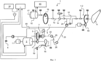
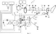
Фиг. 1 - кинематическая схема исполнительного механизма по первому варианту выполнения;FIG. 1 is a kinematic diagram of an actuator according to a first embodiment;
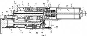
фиг. 2 - вид в продольном разрезе исполнительного механизма на фиг. 1;FIG. 2 is a longitudinal sectional view of the actuator of FIG. one;
фиг. 3 - кинематическая схема исполнительного механизма по второму варианту выполнения;FIG. 3 is a kinematic diagram of an actuator according to a second embodiment;
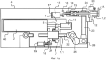
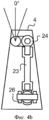
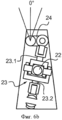
фиг. 4a и фиг. 4b - соответственно вид в продольном разрезе и вид в поперечном разрезе исполнительного механизма на фиг. 3;FIG. 4a and FIG. 4b is a longitudinal sectional view and a cross-sectional view of the actuator of FIG. 3;
фиг. 5 - кинематическая схема исполнительного механизма по третьему варианту выполнения; иFIG. 5 is a kinematic diagram of an actuator according to a third embodiment; and
фиг. 6a и фиг. 6b - соответственно вид в продольном разрезе и вид в поперечном разрезе исполнительного механизма на фиг. 5.FIG. 6a and FIG. 6b is, respectively, a longitudinal sectional view and a cross-sectional view of the actuator of FIG. 5.
Осуществление изобретенияThe implementation of the invention
Со ссылкой на чертежи описываемое ниже изобретение относится к приведению в действие элерона/элевона/интерцептора, подвижно установленного на задней кромке крыла воздушного летательного аппарата. Элерон/элевон/интерцептор крепится к качалке или промежуточному устройству, обозначенному на чертежах ссылочным индексом A.With reference to the drawings, the invention described below relates to the actuation of an aileron / elevon / interceptor movably mounted on the trailing edge of a wing of an aircraft. The aileron / elevon / interceptor is attached to a rocking chair or intermediate device, indicated in the drawings by the reference index A.
Исполнительный механизм изобретения является механизмом электромеханического типа.The actuator of the invention is an electromechanical type mechanism.
В общем, качалка A элерона/элевона/интерцептора приводится в действие через трансмиссию, обозначенную общим ссылочным номером 1, с помощью электродвигателя 2, который управляется двумя электронным блоками 3 управления, получающими сигналы от датчика 50 углового положения.In general, the aileron / elevon / interceptor rocker A is driven through a transmission designated by a
Наличие двух идентичных блоков 3 управления обеспечивает резервирование, когда один из блоков управления заменяет другой блок управления в случае неисправности другого блока.The presence of two identical control units 3 provides redundancy when one of the control units replaces the other control unit in case of failure of the other unit.
В этом примере трансмиссия 1 разделена на две линии для ограничения общей длины и содержит первую линию 1.1 валов и вторую линию 1.2 валов.In this example,
Ниже приводится описание первого варианта выполнения изобретения со ссылкой на фиг. 1 и 2.The following is a description of a first embodiment of the invention with reference to FIG. 1 and 2.
Исполнительный механизм содержит корпус 4, образующий неподвижную конструкцию, и этот корпус крепится в крыле воздушного летательного аппарата, например, болтами, и в нем расположены электродвигатель 2 и трансмиссия 1 для передачи движения.The actuator includes a
Электродвигатель 2 является электродвигателем бесщеточного типа и имеет выходной вал 20, соединенный с трансмиссией 1. При надлежащей подаче питания электродвигатель 2 приводит выходной вал 20 во вращение в одном из двух противоположных направлений вращения, которые упоминаются, соответственно, как первое и второе направления вращения.The
Как известно, трансмиссия 1 содержит ряд зубчатых передач, обеспечивающих получение заданного передаточного числа для перемещения элерона/элевона/интерцептора при заданных условиях его функционирования. В этом примере зубчатые передачи содержат группу 5 последовательно расположенных планетарных зубчатых передач, именуемых «гнездовая передача», и передачу из параллельных шестерней 6. Передача из параллельных шестерней 6 передает движение первой линии 1.1 валов на вторую линию 1.2 валов. Неподвижные наружные кольца планетарных передач с направленными внутрь зубьями крепятся непосредственно к внутренней стенке корпуса 4 для ограничения общего размера исполнительного механизма и упрощения конструкции. Крутящий момент и скорость применительно к передаваемому движению зависят от отношений чисел зубьев между различными шестернями. Эти зубчатые передачи не описываются подробно.As you know,
Ограничитель 7 крутящего момента расположен перед группой 5. Ограничитель 7 крутящего момента является ограничителем фрикционного типа и содержит две пластины, которые упруго прижимаются друг к другу, а именно: входную пластину, которая вращается с выходным валом 20 электродвигателя 2, и выходную пластину, которая вращается с входной шестерней группы 5. Ограничитель 7 крутящего момента обеспечивает пассивное ограничение крутящего момента. Также предусмотрен датчик 8 нагрузки, который соединен с блоком 3 управления, который управляет электродвигателем 2, при этом датчик нагрузки обеспечивает, что нагрузка, действующая на трансмиссию 1, не превышает заданное пороговое значение. Датчик 8 нагрузки генерирует измерительный сигнал применительно к скручиванию вала трансмиссии 1 относительно указателя 9. Измерительный сигнал передается на приемник 10 через преобразователь с целью исключить использование грубой трассировки или контактных колец.The
Трансмиссия 1 также включает в себя демпфер 11, который используется в случае, если электронный блок 3 управления не запитан. В этом примере демпфер 11 расположен за электродвигателем 2 на корпусе 4, и выходной вал 20 имеет конец, который выступает из корпуса 4 и вращается с демпфером 11.
Исполнительный механизм включает в себя муфту 12, которая расположена вблизи выхода из трансмиссии на второй линии 1.2 валов и имеет выход, который соединен с качалкой A. Муфта 12 приводится в действие через устройство линейного исполнительного механизма, содержащее систему 13, 14 винт-гайка, соединенную с поворотным электродвигателем 15 через набор 16 шестерней. Положение гайки 14 устройства исполнительного механизма для муфты 12 определяется датчиком 17. Поворотный электродвигатель 15 соединен с узлом 60 управления полетом воздушного летательного аппарата, так чтобы качалка A свободно перемещалась в случае защемления какого-либо элемента исполнительного механизма.The actuator includes a
Трансмиссия 1 включает в себя храповую собачку 18, оказывающую противодействие трансмиссии для перемещения в первом направлении вращения, и блок 3 управления соединен с элементом 19 освобождения храповой собачки 18, так чтобы обеспечить передачу движения в первом направлении вращения. Храповая собачка 18 имеет один конец, прикрепленный для поворачивания в корпусе 4, и свободный конец, который упруго прижимается к зубьям храпового колеса 21, которое вращается с выходным валом 20 электродвигателя 2. Элемент 19 освобождения храповой собачки содержит электромагнит, который при запитывании удерживает свободный конец храповой собачки 18 на удалении от зубьев храпового колеса 21. Таким образом, когда электромагнит не запитан (элемент освобождения деактивируется), в частности, когда блок 3 управления не запитан (или все блоки управления запитаны, если рассматриваемый элерон/элевон/интерцептор связан с несколькими блоками управления), свободный конец храповой собачки 18 упруго возвращается к зубьям и препятствует перемещению, передаваемому в первом направлении вращения.
Электродвигатель 2. храповая собачка 18, ограничитель 7 крутящего момента, демпфер 11 и зубчатые передачи 5, 6 установлены на первой линии 1.1 валов.
Муфта 12 установлена во второй линии 1.2 валов, которая соединена с качалкой A. Датчик 50 углового положения измерительного преобразователя вращательных перемещений установлен на выходном валу второй линии 1.2 валов.The
В приведенном ниже описании второго и третьего вариантов выполнения изобретения элементы, идентичные или аналогичные элементам, описанным выше, обозначены идентичными цифровыми ссылками.In the following description of the second and third embodiments of the invention, elements identical or similar to the elements described above are denoted by identical digital references.
В вариантах выполнения на фиг. 3-6 трансмиссия 1 показана в упрощенном виде, в частности, что касается ее зубчатых передач.In the embodiments of FIG. 3-6,
Как указано выше, исполнительный механизм содержит корпус 4, содержащий все компоненты исполнительного механизма. Исполнительный механизм включает в себя вспомогательный корпус, образующий усиливающий элемент 40, в котором размещается первая линия 1.1 валов, т.е. электродвигатель 2, ограничитель 7 крутящего момента, демпфер 11, храповая собачка 18, элемент 19 освобождения и храповое колесо 21, и который с помощью шарнира крепится в корпусе 4. Компоновка этих элементов, по существу, такая же, как и в первом варианте выполнения.As indicated above, the actuator comprises a
Вторая линия 1.2 валов и муфта 12 установлены в корпусе 4 снаружи усиливающего элемента 40.The second line 1.2 of the shafts and the
После храповой собачки и ограничителя 7 крутящего момента выход первой линии 1.1 валов соединен с элементом для преобразования вращательного движения в поступательное движение ползуна 22. В этом примере ползун 22 является резьбовой штангой, вставленной в гайку, соединенную с выходом ограничителя 7 крутящего момента. Ползун 22 соединен соединительной штангой 23 с эксцентриковым элементом 24, предназначенным для вращения с валом второй линии 1.2 валов и, таким образом, с элероном/элевоном/интерцептором.After the ratchet dog and the
Выходной вал 20 электродвигателя 2 параллелен поворотной оси элерона/элевона/ интерцептора, и соединительная штанга 23 продолжается в направлении, по существу перпендикулярном поворотной оси элерона/элевона/интерцептора.The
Со ссылкой на фиг. 3 и 4 и по второму варианту выполнения ползун 22 шарнирно крепится к рычагу 25 качалки для поворачивания эксцентрикового пальца 26, с которым соединена соединительная штанга 23.With reference to FIG. 3 and 4, and in the second embodiment, the
Понятно, что поступательное перемещение ползуна 22 вынуждает качалку и узел 25, 26 в сборе поворачиваться, тем самым поступательно перемещая соединительную штангу 23 и толкая или вытягивая эксцентриковый элемент 24 и вынуждая поворачиваться выходной вал второй линии 1.2 валов трансмиссии 1.It is clear that the translational movement of the
Со ссылкой на фиг. 5 и 6 и по третьему варианту выполнения соединительная штанга 23 содержит первый сегмент 23.1, шарнирно соединенный с эксцентриковым элементом 24 и с ползуном 22, и второй сегмент 23.2, шарнирно соединенный с корпусом 4 и ползуном 22.With reference to FIG. 5 and 6, and in the third embodiment, the connecting
Понятно, что поступательное перемещение ползуна 22 изменяет угол между сегментами 23.1 и 23.2 соединительной штанги и, таким образом, изменяет расстояние между концом сегмента 23.1, соединенным с эксцентриковым элементом 24, и концом сегмента 23.2, соединенным с корпусом 4. Конец сегмента 23.1, соединенный с эксцентриковым элементом 24, перемещает эксцентриковый элемент 24 и вынуждает поворачиваться выходной вал второй линии 1.2 валов трансмиссии 1.It is understood that the translational movement of the
Разумеется, изобретение не ограничивается до описанных вариантов выполнения и распространяется на любой вариант, соответствующий объему изобретения, как определено в формуле изобретения.Of course, the invention is not limited to the described embodiments, and extends to any embodiment that is within the scope of the invention as defined in the claims.
В частности, трансмиссия может быть конструкцией, которая отличается от описанной конструкции. Положения муфты, ограничителя крутящего момента, храповой собачки и зубчатых передач могут быть модифицированы. Трансмиссия и линии валов могут содержать сегменты, которые являются концентричными или параллельными. Линии валов могут быть параллельными или они могут быть наклонены относительно друг друга.In particular, the transmission may be a structure that is different from the described structure. The positions of the clutch, torque limiter, ratchet dog and gears can be modified. The transmission and shaft lines may contain segments that are concentric or parallel. The shaft lines may be parallel or they may be inclined relative to each other.
Храповая собачка может быть предусмотрена для каждого направления вращения.A ratchet dog may be provided for each direction of rotation.
Во втором и третьем вариантах выполнения шарнирное соединение между усиливающим элементом 40 и корпусом 4 с помощью сферического шарнира является оптимальным, и такое соединение может быть внедрено в первую линию валов.In the second and third embodiments, the articulation between the reinforcing
Также можно исключить внедрение исполнительного механизма в корпус или внедрить в корпус только часть исполнительного механизма. Корпус 4 может быть заменен опорной конструкцией.You can also exclude the introduction of the actuator into the housing or introduce only part of the actuator into the housing. The
Демпфер 11 может быть установлен между передним концом выходного вала и усиливающим элементом 40.
Claims (7)
Applications Claiming Priority (5)
| Application Number | Priority Date | Filing Date | Title |
|---|---|---|---|
| US201161562736P | 2011-11-22 | 2011-11-22 | |
| US61/562,736 | 2011-11-22 | ||
| FR1253023 | 2012-04-02 | ||
| FR1253023A FR2988797B1 (en) | 2012-04-02 | 2012-04-02 | ELECTROMECHANICAL FLOATING SURFACE ACTUATOR FOR AIRCRAFT AND AIRCRAFT PROVIDED WITH SUCH AN ACTUATOR |
| PCT/EP2012/073264 WO2013076158A1 (en) | 2011-11-22 | 2012-11-21 | An electromechanical actuator for an aircraft control surface, and an aircraft provided with such an actuator |
Publications (1)
| Publication Number | Publication Date |
|---|---|
| RU2561159C1 true RU2561159C1 (en) | 2015-08-27 |
Family
ID=48469155
Family Applications (1)
| Application Number | Title | Priority Date | Filing Date |
|---|---|---|---|
| RU2014125270/11A RU2561159C1 (en) | 2011-11-22 | 2012-11-21 | Electromechanical actuator for aircraft control airfoil and aircraft equipped with such actuator |
Country Status (9)
| Country | Link |
|---|---|
| US (1) | US9038944B2 (en) |
| EP (1) | EP2783135B1 (en) |
| CN (1) | CN103946590B (en) |
| BR (1) | BR112014012105A8 (en) |
| CA (1) | CA2854239C (en) |
| FR (1) | FR2988797B1 (en) |
| IN (1) | IN2014CN04486A (en) |
| RU (1) | RU2561159C1 (en) |
| WO (1) | WO2013076158A1 (en) |
Families Citing this family (7)
| Publication number | Priority date | Publication date | Assignee | Title |
|---|---|---|---|---|
| US9493230B2 (en) | 2013-11-21 | 2016-11-15 | Hamilton Sundstrand Corporation | Drive assembly with selective disconnect |
| FR3016607B1 (en) * | 2014-01-20 | 2016-01-22 | Sagem Defense Securite | ACTUATOR FOR CONTROLLING A HORIZONTAL STABILIZATION PLAN OF AN AIRCRAFT |
| EP3143306B1 (en) * | 2014-05-16 | 2021-06-23 | Bombardier Inc. | Actuators and methods for aircraft flight control surfaces |
| FR3022526B1 (en) * | 2014-06-20 | 2016-06-24 | Sagem Defense Securite | ELECTROMECHANICAL ACTUATOR WITH MAGNETIC TORQUE LIMITER |
| EP3324079B1 (en) * | 2016-11-21 | 2020-04-29 | Ratier-Figeac SAS | Flight control system and method of manufacturing a flight control system |
| FR3058983B1 (en) * | 2016-11-22 | 2018-11-02 | Safran Electronics & Defense | EASILY MOUNTED ACTUATOR |
| EP3739230B1 (en) * | 2019-05-16 | 2022-04-27 | Ratier-Figeac SAS | Actuator with declutchable output lever |
Citations (3)
| Publication number | Priority date | Publication date | Assignee | Title |
|---|---|---|---|---|
| US4762205A (en) * | 1987-05-20 | 1988-08-09 | Simmonds Precision | Flight control surface actuator for aircraft including remote braking failure detection |
| DE4413854A1 (en) * | 1994-04-21 | 1995-10-26 | Daimler Benz Aerospace Airbus | Pivoting device for electromechanically driven aircraft wing spoiler |
| RU2277195C2 (en) * | 2003-02-07 | 2006-05-27 | Государственное предприятие "Харьковское агрегатное конструкторское бюро" (ГП "ХАКБ") | Driving electric mechanism |
Family Cites Families (11)
| Publication number | Priority date | Publication date | Assignee | Title |
|---|---|---|---|---|
| DE2725632C2 (en) * | 1977-06-07 | 1982-11-11 | Messerschmitt-Bölkow-Blohm GmbH, 8000 München | Ailerons and flap drives for an aircraft |
| US4637272A (en) * | 1985-10-28 | 1987-01-20 | Sundstrand Corporation | Ballscrew actuator |
| US5918836A (en) * | 1997-03-25 | 1999-07-06 | Sundstrand Corporation | Aircraft spoiler blow-down mechanism |
| US6109415A (en) * | 1998-05-29 | 2000-08-29 | The Boeing Company | Bi-directional ballscrew no-back device |
| JP4182726B2 (en) * | 2002-02-20 | 2008-11-19 | 日本精工株式会社 | Linear actuator |
| US7100870B2 (en) * | 2003-10-15 | 2006-09-05 | Parker-Hannifin Corporation | Jam tolerant electromechanical actuation systems and methods of operation |
| DE102005062919A1 (en) * | 2005-12-29 | 2007-07-12 | Airbus Deutschland Gmbh | Airfoil for aircraft, has flap attached to supports and rotates with respect to axis during rotation of supports relative to wingbox, computer evaluating output signals from sensors and controlling drives on basis of evaluation |
| US8230750B2 (en) * | 2006-09-01 | 2012-07-31 | Parker-Hannifin Corporation | Electromechanical actuating assembly |
| US8136418B2 (en) * | 2007-02-07 | 2012-03-20 | Parker-Hannifin Corporation | Electromechanical actuating assembly |
| DE102008022092A1 (en) * | 2008-05-05 | 2009-11-19 | Airbus Deutschland Gmbh | Fault-tolerant control system for adjusting the flaps of an aircraft with adjustable kinematics with a fixed axis of rotation |
| US8794084B2 (en) * | 2010-03-18 | 2014-08-05 | Parker-Hannifin Corporation | Jam-tolerant electromechanical actuator |
-
2012
- 2012-04-02 FR FR1253023A patent/FR2988797B1/en active Active
- 2012-11-21 BR BR112014012105A patent/BR112014012105A8/en not_active IP Right Cessation
- 2012-11-21 EP EP12788544.0A patent/EP2783135B1/en active Active
- 2012-11-21 US US14/358,651 patent/US9038944B2/en active Active
- 2012-11-21 RU RU2014125270/11A patent/RU2561159C1/en not_active IP Right Cessation
- 2012-11-21 CA CA2854239A patent/CA2854239C/en not_active Expired - Fee Related
- 2012-11-21 WO PCT/EP2012/073264 patent/WO2013076158A1/en active Application Filing
- 2012-11-21 CN CN201280057269.2A patent/CN103946590B/en active Active
- 2012-11-21 IN IN4486CHN2014 patent/IN2014CN04486A/en unknown
Patent Citations (3)
| Publication number | Priority date | Publication date | Assignee | Title |
|---|---|---|---|---|
| US4762205A (en) * | 1987-05-20 | 1988-08-09 | Simmonds Precision | Flight control surface actuator for aircraft including remote braking failure detection |
| DE4413854A1 (en) * | 1994-04-21 | 1995-10-26 | Daimler Benz Aerospace Airbus | Pivoting device for electromechanically driven aircraft wing spoiler |
| RU2277195C2 (en) * | 2003-02-07 | 2006-05-27 | Государственное предприятие "Харьковское агрегатное конструкторское бюро" (ГП "ХАКБ") | Driving electric mechanism |
Also Published As
| Publication number | Publication date |
|---|---|
| IN2014CN04486A (en) | 2015-09-11 |
| BR112014012105A8 (en) | 2017-06-20 |
| EP2783135B1 (en) | 2017-03-22 |
| EP2783135A1 (en) | 2014-10-01 |
| CA2854239C (en) | 2016-06-14 |
| CN103946590B (en) | 2016-09-28 |
| FR2988797B1 (en) | 2015-04-24 |
| CN103946590A (en) | 2014-07-23 |
| CA2854239A1 (en) | 2013-05-30 |
| BR112014012105A2 (en) | 2017-06-13 |
| WO2013076158A1 (en) | 2013-05-30 |
| US9038944B2 (en) | 2015-05-26 |
| FR2988797A1 (en) | 2013-10-04 |
| US20140326828A1 (en) | 2014-11-06 |
Similar Documents
| Publication | Publication Date | Title |
|---|---|---|
| RU2561159C1 (en) | Electromechanical actuator for aircraft control airfoil and aircraft equipped with such actuator | |
| US10538310B2 (en) | Near synchronous distributed hydraulic motor driven actuation system | |
| US10066715B2 (en) | Fail-safe electromechanical actuator | |
| EP1380500A2 (en) | Flight surface actuator | |
| EP3101279A1 (en) | Redundant speed summing actuators | |
| US9829055B2 (en) | Electromechanical actuator comprising a mechanical roller torque limiter | |
| CN109850126A (en) | A kind of aircraft handling modularization comprehensive control device | |
| CN106458317B (en) | Actuator for flight-control surfaces | |
| US9735647B2 (en) | Electromagnetic actuator with magnetic torque limiter | |
| CN104290901A (en) | Double-rocker transmission mechanism applicable to movable control surface of aerial vehicle | |
| EP2980451B1 (en) | Actuator device with rotary flexure mechanism | |
| CN109982927B (en) | Actuator easy to install | |
| EP3050796A1 (en) | Method for adjusting the play in a high-lift system of an aircraft | |
| KR20120134027A (en) | A twist mechanism for twisting a rotor blade for a rotorcraft, and a blade | |
| US3030052A (en) | Mechanical remote control system | |
| US10001188B2 (en) | Electromechanical actuator comprising a dual-function braking device | |
| US11603185B2 (en) | Synchronization system for distributed electromechanical actuation system | |
| KR102177027B1 (en) | Power transmission device of electric drive device for aircraft | |
| EP3038907B1 (en) | Multi-plate clutch | |
| CA2808254C (en) | A wing control system | |
| CN111038693B (en) | Mechanical control system of multi-rotor aircraft | |
| EP4079631A1 (en) | Rotary actuation for thin wing applications | |
| GB2390344A (en) | Flight surface actuator |
Legal Events
| Date | Code | Title | Description |
|---|---|---|---|
| PD4A | Correction of name of patent owner | ||
| MM4A | The patent is invalid due to non-payment of fees |
Effective date: 20201122 |