EP2783135B1 - An electromechanical actuator for an aircraft control surface, and an aircraft provided with such an actuator - Google Patents
An electromechanical actuator for an aircraft control surface, and an aircraft provided with such an actuator Download PDFInfo
- Publication number
- EP2783135B1 EP2783135B1 EP12788544.0A EP12788544A EP2783135B1 EP 2783135 B1 EP2783135 B1 EP 2783135B1 EP 12788544 A EP12788544 A EP 12788544A EP 2783135 B1 EP2783135 B1 EP 2783135B1
- Authority
- EP
- European Patent Office
- Prior art keywords
- actuator
- transmission
- movement
- pawl
- control surface
- Prior art date
- Legal status (The legal status is an assumption and is not a legal conclusion. Google has not performed a legal analysis and makes no representation as to the accuracy of the status listed.)
- Active
Links
- 230000005540 biological transmission Effects 0.000 claims description 25
- RZVHIXYEVGDQDX-UHFFFAOYSA-N 9,10-anthraquinone Chemical compound C1=CC=C2C(=O)C3=CC=CC=C3C(=O)C2=C1 RZVHIXYEVGDQDX-UHFFFAOYSA-N 0.000 claims description 13
- 230000001131 transforming effect Effects 0.000 claims description 2
- 238000010586 diagram Methods 0.000 description 3
- 238000005259 measurement Methods 0.000 description 2
- 238000011144 upstream manufacturing Methods 0.000 description 1
Images


Classifications
-
- B—PERFORMING OPERATIONS; TRANSPORTING
- B64—AIRCRAFT; AVIATION; COSMONAUTICS
- B64C—AEROPLANES; HELICOPTERS
- B64C13/00—Control systems or transmitting systems for actuating flying-control surfaces, lift-increasing flaps, air brakes, or spoilers
- B64C13/24—Transmitting means
- B64C13/26—Transmitting means without power amplification or where power amplification is irrelevant
- B64C13/28—Transmitting means without power amplification or where power amplification is irrelevant mechanical
- B64C13/341—Transmitting means without power amplification or where power amplification is irrelevant mechanical having duplication or stand-by provisions
-
- B—PERFORMING OPERATIONS; TRANSPORTING
- B64—AIRCRAFT; AVIATION; COSMONAUTICS
- B64C—AEROPLANES; HELICOPTERS
- B64C13/00—Control systems or transmitting systems for actuating flying-control surfaces, lift-increasing flaps, air brakes, or spoilers
- B64C13/24—Transmitting means
-
- F—MECHANICAL ENGINEERING; LIGHTING; HEATING; WEAPONS; BLASTING
- F16—ENGINEERING ELEMENTS AND UNITS; GENERAL MEASURES FOR PRODUCING AND MAINTAINING EFFECTIVE FUNCTIONING OF MACHINES OR INSTALLATIONS; THERMAL INSULATION IN GENERAL
- F16H—GEARING
- F16H21/00—Gearings comprising primarily only links or levers, with or without slides
- F16H21/10—Gearings comprising primarily only links or levers, with or without slides all movement being in, or parallel to, a single plane
- F16H21/16—Gearings comprising primarily only links or levers, with or without slides all movement being in, or parallel to, a single plane for interconverting rotary motion and reciprocating motion
- F16H21/18—Crank gearings; Eccentric gearings
- F16H21/22—Crank gearings; Eccentric gearings with one connecting-rod and one guided slide to each crank or eccentric
-
- F—MECHANICAL ENGINEERING; LIGHTING; HEATING; WEAPONS; BLASTING
- F16—ENGINEERING ELEMENTS AND UNITS; GENERAL MEASURES FOR PRODUCING AND MAINTAINING EFFECTIVE FUNCTIONING OF MACHINES OR INSTALLATIONS; THERMAL INSULATION IN GENERAL
- F16H—GEARING
- F16H35/00—Gearings or mechanisms with other special functional features
- F16H2035/005—Gearings or mechanisms preventing back-driving
-
- Y—GENERAL TAGGING OF NEW TECHNOLOGICAL DEVELOPMENTS; GENERAL TAGGING OF CROSS-SECTIONAL TECHNOLOGIES SPANNING OVER SEVERAL SECTIONS OF THE IPC; TECHNICAL SUBJECTS COVERED BY FORMER USPC CROSS-REFERENCE ART COLLECTIONS [XRACs] AND DIGESTS
- Y10—TECHNICAL SUBJECTS COVERED BY FORMER USPC
- Y10T—TECHNICAL SUBJECTS COVERED BY FORMER US CLASSIFICATION
- Y10T74/00—Machine element or mechanism
- Y10T74/18—Mechanical movements
- Y10T74/18056—Rotary to or from reciprocating or oscillating
- Y10T74/18184—Crank, pitman, and lever
-
- Y—GENERAL TAGGING OF NEW TECHNOLOGICAL DEVELOPMENTS; GENERAL TAGGING OF CROSS-SECTIONAL TECHNOLOGIES SPANNING OVER SEVERAL SECTIONS OF THE IPC; TECHNICAL SUBJECTS COVERED BY FORMER USPC CROSS-REFERENCE ART COLLECTIONS [XRACs] AND DIGESTS
- Y10—TECHNICAL SUBJECTS COVERED BY FORMER USPC
- Y10T—TECHNICAL SUBJECTS COVERED BY FORMER US CLASSIFICATION
- Y10T74/00—Machine element or mechanism
- Y10T74/18—Mechanical movements
- Y10T74/18568—Reciprocating or oscillating to or from alternating rotary
- Y10T74/18576—Reciprocating or oscillating to or from alternating rotary including screw and nut
- Y10T74/18696—Reciprocating or oscillating to or from alternating rotary including screw and nut including means to selectively transmit power [e.g., clutch, etc.]
-
- Y—GENERAL TAGGING OF NEW TECHNOLOGICAL DEVELOPMENTS; GENERAL TAGGING OF CROSS-SECTIONAL TECHNOLOGIES SPANNING OVER SEVERAL SECTIONS OF THE IPC; TECHNICAL SUBJECTS COVERED BY FORMER USPC CROSS-REFERENCE ART COLLECTIONS [XRACs] AND DIGESTS
- Y10—TECHNICAL SUBJECTS COVERED BY FORMER USPC
- Y10T—TECHNICAL SUBJECTS COVERED BY FORMER US CLASSIFICATION
- Y10T74/00—Machine element or mechanism
- Y10T74/18—Mechanical movements
- Y10T74/18568—Reciprocating or oscillating to or from alternating rotary
- Y10T74/18792—Reciprocating or oscillating to or from alternating rotary including worm
Definitions
- the present invention relates to an electromechanical actuator of a movable flight control surface of an aircraft such as an airplane.
- a flight control surface is an aileron, an elevon, or a spoiler.
- an electromechanical actuator of a movable flight control surface of an aircraft comprises an electric motor having an outlet shaft with first and second directions of rotation, and a movement transmission arranged to connect the outlet shaft of the motor to the movable flight control surface.
- the motor is controlled by a control unit that receives commands from the flight control unit of the aircraft.
- An object of the invention is to provide means for remedying the above-mentioned drawback.
- the invention provides an electromechanical actuator for a movable flight control surface of an aircraft, the actuator comprising an electric motor having an outlet shaft with first and second directions of rotation, a movement transmission arranged to connect the outlet shaft of the motor to the movable flight control surface, and a control unit for controlling the motor.
- the transmission incorporates a pawl device arranged to oppose the transmission of movement in the first direction of rotation, and the control unit is connected to a pawl declutching member for declutching the pawl and enabling movement to be transmitted in the first direction of rotation.
- the invention also provides an aircraft having wings, each provided with at least one movable airfoil surface of the aileron, the elevon or the spoiler type associated with at least one such actuator, the actuator being mounted so that the pawl opposes a deflection movement of the airfoil surface.
- the invention is described herein in its application to actuating an aileron / elevon / spoiler that is movably mounted at the rear edge of an aircraft wing.
- the aileron, the elevon or the spoiler is secured to a crank or interface referenced A in the figures.
- the actuator of the invention is of the electromechanical type.
- crank A of the aileron / elevon / spoiler is actuated via a transmission given overall reference 1 by an electric motor 2 that is controlled by two electronic control units 3 receiving signals from an angle position sensor 50.
- the presence of two identical control units 3 provides redundancy, enabling one of the control units to take the place of the other in the event of the other unit failing.
- the transmission 1 is split in two lines in order to limit its overall length so that it comprises a first line of shafts 1.1 and a second line of shafts 1.2.
- the actuator comprises a casing 4 forming a stationary structure, which casing is arranged to be fastened in the wing of the aircraft, e.g. by bolts, and receives the motor 2 and the movement transmission 1.
- the motor 2 is of the brushless type and has an outlet shaft 20 connected to the transmission 1.
- the motor 2 is arranged, when appropriately powered, to set its outlet shaft 20 into rotation in either of two opposite directions of rotation that are referred to herein respectively as the first and second directions of rotation.
- the transmission 1 comprises a succession of gear trains enabling a predetermined reduction ratio to be obtained for moving the aileron, the elevon or the spoiler under the conditions imposed for its operation.
- the gear trains comprise a group 5 of epicyclic gear trains in series referred to as the "nested train", and a train of parallel gears 6.
- the train of parallel gears 6 transmits the movement of the first line of shafts 1.1 to the second line of shafts 1.2.
- the stationary outside rings of the epicyclic trains with inwardly-directed sets of teeth are secured directly to the inside wall of the casing 4 so as to limit the overall size of the actuator and so as to simplify its structure.
- the torque and the speed of the transmitted movement depend on the ratios of the numbers of teeth between the various gears.
- a torque limiter 7 is located upstream from the group 5.
- the torque limiter 7 is of the friction type and comprises two plates that are urged resiliently one against the other, namely an inlet plate constrained to rotate with the outlet shaft 20 of the motor 2, and an outlet plate constrained to rotate with the inlet gear of the group 5.
- the torque limiter 7 provides passive torque limiting.
- a load sensor 8 is also provided that is connected to the control unit 3 controlling the motor 2 to ensure that the load exerted on the transmission 1 does not exceed a predetermined threshold.
- the load sensor 8 generates a measurement signal representative of the twisting of the shaft of the transmission 1 relative to a pointer 9.
- the measurement signal is transmitted to a receiver 10 via a transformer to avoid using any loose wiring or slip rings.
- the transmission 1 also includes a damper 11 that acts in the event of the electronic control unit 3 not being electrically powered.
- the damper 11 is located behind the motor 2 on the casing 4, and the outlet shaft 20 has an end that projects from the casing 4 and that is constrained to rotate with the damper 11.
- the actuator includes a clutch 12 that is located in the vicinity of the outlet from the transmission on the second line of shafts 1.2, and that has an outlet that is connected to the crank A.
- the clutch 12 is actuated via a linear actuator device comprising a screw-and-nut system 13, 14 connected to a rotary electric motor 15 via a set of gears 16.
- the position of the nut 14 of the actuator device for the clutch 12 is determined by a sensor 17.
- the rotary electric motor 15 is connected to the flight control center (FCC) 60 of the aircraft in order to allow the crank A to move freely in the event of any of the elements of the actuator jamming.
- FCC flight control center
- the transmission 1 incorporates a pawl device 18 arranged to oppose the transmission of movement in the first direction of rotation, and the control unit 3 is connected to a pawl declutching member 19 for declutching the pawl 18 so as to allow movement to be transmitted in the first direction of rotation.
- the pawl 18 has one end mounted to pivot in the casing 4 and a free end that is urged resiliently to bear against the teeth of a ratchet wheel 21 constrained to rotate with the outlet shaft 20 of the motor 2.
- the pawl declutching member 19 comprises an electromagnet that, when powered, holds the free end of the pawl 18 apart from the teeth of the ratchet wheel 21.
- the electromagnet when the electromagnet is not powered (the declutching member is then deactivated), in particular when the control unit 3 is not electrically powered (or all of the control units are powered if the aileron, or the elevon or the spoiler in question is associated with a plurality of control units) the free end of the pawl 18 is returned resiliently against the teeth and prevents movement being transmitted in the first direction of rotation.
- the motor 2, the pawl device 18, the torque limiter 7, the damper 11, and the gear trains 5, 6, are mounted on the first line of shafts 1.1.
- the clutch 12 is mounted on the second line of shafts 1.2, which is connected to the crank A.
- the angle position sensor 50 of the rotary variable differential transformer (RVDT) type, is mounted on the outlet shaft of the second line of shafts 1.2.
- the transmission 1 is shown in simplified manner, in particular concerning its gear trains.
- the actuator comprises a casing 4 containing all of the components of the actuator.
- the actuator includes a secondary casing forming a strength member 40 that receives the first line of shafts 1.1, i.e. the motor 2, the torque limiter 7, the damper 11, the pawl device 18, the declutching member 19, and the ratchet wheel 21, and that is fastened via a hinge in the casing 4.
- the arrangement of these elements is substantially the same as in the first embodiment.
- the second line of shafts 1.2 and the clutch 12 are mounted in the casing 4 outside the strength member 40.
- the outlet from the first line of shafts 1.1 is connected to a member for transforming rotary movement into movement in translation of a slide 22.
- the slide 22 is a threaded rod fitted in a nut secured to the outlet of the torque limiter 7.
- the slide 22 is connected by a connecting rod 23 to an eccentric portion 24 constrained to rotate with a shaft of the second line of shafts 1.2 and thus with the aileron, the elevon or the spoiler.
- the outlet shaft 20 of the electric motor 2 is parallel to a pivot axis of the aileron, the elevon or the spoiler, and the connecting rod 23 extends in a direction substantially perpendicular to the pivot axis of the aileron, the elevon or the spoiler.
- the slide 22 is hinged to a crank lever 25 for turning an eccentric crank pin 26 to which the connecting rod 23 is connected.
- the connecting rod 23 comprises a first segment 23.1 hinged to the eccentric portion 24 and to the slide 22, and a second segment 23.2 hinged to the casing 4 and to the slide 22.
- moving the slide 22 in translation changes the angle between the connecting rod segments 23.1 and 23.2, and thus changes the spacing between the end of the segment 23.1 connected to the eccentric portion 24 and the end of the segment 23.2 connected to the casing 4.
- the end of the segment 23.1 connected to the eccentric portion 24 moves the eccentric portion 24 and causes the outlet shaft of the second line of shafts 1.2 of the transmission 1 to pivot.
- the transmission may be of a structure different from that described.
- the positions of the clutch, of the torque limiter, of the pawl device, and of the gear trains may be modified.
- the transmission and the lines of shafts may comprise segments that are coaxial or parallel.
- the lines of shafts may be parallel or they may be inclined relative to each other...
- the hinge between the strength member 40 and the casing 4 via a ball joint connection is optional, it being possible for such a connection to be incorporated in the first line of shafts.
- the casing 4 may be replaced by a support structure.
- the damper 11 may be mounted between the front end of the outlet shaft and the strength member 40.
Description
- The present invention relates to an electromechanical actuator of a movable flight control surface of an aircraft such as an airplane. By way of example, such a flight control surface is an aileron, an elevon, or a spoiler.
- In general, an electromechanical actuator of a movable flight control surface of an aircraft comprises an electric motor having an outlet shaft with first and second directions of rotation, and a movement transmission arranged to connect the outlet shaft of the motor to the movable flight control surface. The motor is controlled by a control unit that receives commands from the flight control unit of the aircraft.
- The loss of power to such actuators can lead to consequences that are catastrophic by allowing the aileron, the elevon or the spoiler to move in a way that risks unbalancing the aircraft, increasing its drag, or damaging its structure by the resulting vibration (a phenomenon known as "flutter").
- Document
WO 98/42567 claim 1. - An object of the invention is to provide means for remedying the above-mentioned drawback.
- To this end, the invention provides an electromechanical actuator for a movable flight control surface of an aircraft, the actuator comprising an electric motor having an outlet shaft with first and second directions of rotation, a movement transmission arranged to connect the outlet shaft of the motor to the movable flight control surface, and a control unit for controlling the motor. The transmission incorporates a pawl device arranged to oppose the transmission of movement in the first direction of rotation, and the control unit is connected to a pawl declutching member for declutching the pawl and enabling movement to be transmitted in the first direction of rotation.
- Thus, there is no need to power the motor in order to oppose movement in the first direction of rotation.
- The invention also provides an aircraft having wings, each provided with at least one movable airfoil surface of the aileron, the elevon or the spoiler type associated with at least one such actuator, the actuator being mounted so that the pawl opposes a deflection movement of the airfoil surface.
- Other characteristics and advantages invention appear on reading the following description of particular, nonlimiting embodiments of the invention.
- Reference is made to the accompanying drawings, in which:
-
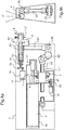
Figure 1 is a kinematic diagram of an actuator in a first embodiment; not being part of the invention -
Figure 2 is a longitudinal section view of theFigure 1 actuator; -
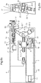
Figure 3 is a kinematic diagram of an actuator in a second embodiment; -
Figure 4a and Figure 4b are respectively a longitudinal section view and a cross section view of theFigure 3 actuator; -
Figure 5 is a kinematic diagram of an actuator in a third embodiment; and -
Figure 6a and Figure 6b are respectively a longitudinal section view and a cross section view of theFigure 5 actuator. - With reference to the figures, the invention is described herein in its application to actuating an aileron / elevon / spoiler that is movably mounted at the rear edge of an aircraft wing. The aileron, the elevon or the spoiler is secured to a crank or interface referenced A in the figures.
- The actuator of the invention is of the electromechanical type.
- In outline, the crank A of the aileron / elevon / spoiler is actuated via a transmission given
overall reference 1 by anelectric motor 2 that is controlled by two electronic control units 3 receiving signals from anangle position sensor 50. The presence of two identical control units 3 provides redundancy, enabling one of the control units to take the place of the other in the event of the other unit failing. - In this example, the
transmission 1 is split in two lines in order to limit its overall length so that it comprises a first line of shafts 1.1 and a second line of shafts 1.2. - The first embodiment is described below with reference to
Figures 1 and2 . - The actuator comprises a
casing 4 forming a stationary structure, which casing is arranged to be fastened in the wing of the aircraft, e.g. by bolts, and receives themotor 2 and themovement transmission 1. - The
motor 2 is of the brushless type and has anoutlet shaft 20 connected to thetransmission 1. Themotor 2 is arranged, when appropriately powered, to set itsoutlet shaft 20 into rotation in either of two opposite directions of rotation that are referred to herein respectively as the first and second directions of rotation. - In known manner, the
transmission 1 comprises a succession of gear trains enabling a predetermined reduction ratio to be obtained for moving the aileron, the elevon or the spoiler under the conditions imposed for its operation. In this example, the gear trains comprise agroup 5 of epicyclic gear trains in series referred to as the "nested train", and a train ofparallel gears 6. The train ofparallel gears 6 transmits the movement of the first line of shafts 1.1 to the second line of shafts 1.2. The stationary outside rings of the epicyclic trains with inwardly-directed sets of teeth are secured directly to the inside wall of thecasing 4 so as to limit the overall size of the actuator and so as to simplify its structure. The torque and the speed of the transmitted movement depend on the ratios of the numbers of teeth between the various gears. These gear trains are not described in detail herein. - A
torque limiter 7 is located upstream from thegroup 5. Thetorque limiter 7 is of the friction type and comprises two plates that are urged resiliently one against the other, namely an inlet plate constrained to rotate with theoutlet shaft 20 of themotor 2, and an outlet plate constrained to rotate with the inlet gear of thegroup 5. Thetorque limiter 7 provides passive torque limiting. Aload sensor 8 is also provided that is connected to the control unit 3 controlling themotor 2 to ensure that the load exerted on thetransmission 1 does not exceed a predetermined threshold. Theload sensor 8 generates a measurement signal representative of the twisting of the shaft of thetransmission 1 relative to apointer 9. The measurement signal is transmitted to areceiver 10 via a transformer to avoid using any loose wiring or slip rings. - The
transmission 1 also includes adamper 11 that acts in the event of the electronic control unit 3 not being electrically powered. In this example, thedamper 11 is located behind themotor 2 on thecasing 4, and theoutlet shaft 20 has an end that projects from thecasing 4 and that is constrained to rotate with thedamper 11. - The actuator includes a
clutch 12 that is located in the vicinity of the outlet from the transmission on the second line of shafts 1.2, and that has an outlet that is connected to the crank A. Theclutch 12 is actuated via a linear actuator device comprising a screw-and-nut system electric motor 15 via a set ofgears 16. The position of thenut 14 of the actuator device for theclutch 12 is determined by asensor 17. The rotaryelectric motor 15 is connected to the flight control center (FCC) 60 of the aircraft in order to allow the crank A to move freely in the event of any of the elements of the actuator jamming. - The
transmission 1 incorporates apawl device 18 arranged to oppose the transmission of movement in the first direction of rotation, and the control unit 3 is connected to apawl declutching member 19 for declutching thepawl 18 so as to allow movement to be transmitted in the first direction of rotation. Thepawl 18 has one end mounted to pivot in thecasing 4 and a free end that is urged resiliently to bear against the teeth of aratchet wheel 21 constrained to rotate with theoutlet shaft 20 of themotor 2. Thepawl declutching member 19 comprises an electromagnet that, when powered, holds the free end of thepawl 18 apart from the teeth of theratchet wheel 21. Thus, when the electromagnet is not powered (the declutching member is then deactivated), in particular when the control unit 3 is not electrically powered (or all of the control units are powered if the aileron, or the elevon or the spoiler in question is associated with a plurality of control units) the free end of thepawl 18 is returned resiliently against the teeth and prevents movement being transmitted in the first direction of rotation. - The
motor 2, thepawl device 18, thetorque limiter 7, thedamper 11, and thegear trains - The
clutch 12 is mounted on the second line of shafts 1.2, which is connected to the crank A. Theangle position sensor 50, of the rotary variable differential transformer (RVDT) type, is mounted on the outlet shaft of the second line of shafts 1.2. - Elements identical or analogous to those described above are given identical numerical references in the description below of second and third embodiments of the invention.
- In the embodiments of
Figures 3 to 6 , thetransmission 1 is shown in simplified manner, in particular concerning its gear trains. - As above, the actuator comprises a
casing 4 containing all of the components of the actuator. The actuator includes a secondary casing forming astrength member 40 that receives the first line of shafts 1.1, i.e. themotor 2, thetorque limiter 7, thedamper 11, thepawl device 18, the declutchingmember 19, and theratchet wheel 21, and that is fastened via a hinge in thecasing 4. The arrangement of these elements is substantially the same as in the first embodiment. - The second line of shafts 1.2 and the
clutch 12 are mounted in thecasing 4 outside thestrength member 40. - Downstream from the pawl device and the
torque limiter 7, the outlet from the first line of shafts 1.1 is connected to a member for transforming rotary movement into movement in translation of aslide 22. In this example, theslide 22 is a threaded rod fitted in a nut secured to the outlet of thetorque limiter 7. Theslide 22 is connected by a connectingrod 23 to aneccentric portion 24 constrained to rotate with a shaft of the second line of shafts 1.2 and thus with the aileron, the elevon or the spoiler. - The
outlet shaft 20 of theelectric motor 2 is parallel to a pivot axis of the aileron, the elevon or the spoiler, and the connectingrod 23 extends in a direction substantially perpendicular to the pivot axis of the aileron, the elevon or the spoiler. - With reference to
Figures 3 and4 , and in accordance with the second embodiment, theslide 22 is hinged to acrank lever 25 for turning aneccentric crank pin 26 to which the connectingrod 23 is connected. - It can be understood that movement in translation of the
slide 22 causes the crank and crankpin assembly rod 23 in translation so as to push or pull theeccentric portion 24 and cause the outlet shaft of the second line of shafts 1.2 of thetransmission 1 to pivot. - With reference to
Figures 5 and6 , and in accordance with the third embodiment, the connectingrod 23 comprises a first segment 23.1 hinged to theeccentric portion 24 and to theslide 22, and a second segment 23.2 hinged to thecasing 4 and to theslide 22. - It can be understood that moving the
slide 22 in translation changes the angle between the connecting rod segments 23.1 and 23.2, and thus changes the spacing between the end of the segment 23.1 connected to theeccentric portion 24 and the end of the segment 23.2 connected to thecasing 4. The end of the segment 23.1 connected to theeccentric portion 24 moves theeccentric portion 24 and causes the outlet shaft of the second line of shafts 1.2 of thetransmission 1 to pivot. - Naturally, the invention is not limited to the embodiments described, but covers any variant coming within the ambit of the invention as defined by the claims.
- In particular, the transmission may be of a structure different from that described. The positions of the clutch, of the torque limiter, of the pawl device, and of the gear trains may be modified. The transmission and the lines of shafts may comprise segments that are coaxial or parallel. The lines of shafts may be parallel or they may be inclined relative to each other...
- It is possible to provide a pawl device for each direction of rotation.
- In the second and third embodiments, the hinge between the
strength member 40 and thecasing 4 via a ball joint connection is optional, it being possible for such a connection to be incorporated in the first line of shafts. - It is also possible to avoid incorporating the actuator in a casing, or to incorporate only a portion of the actuator in a casing. The
casing 4 may be replaced by a support structure. - The
damper 11 may be mounted between the front end of the outlet shaft and thestrength member 40.
Claims (7)
- An electromechanical actuator for a movable flight control surface of an aircraft, the actuator comprising an electric motor (2) having an outlet shaft (20) with first and second directions of rotation, a movement transmission (1) arranged to connect the outlet shaft of the motor to the movable flight control surface, and a control unit (3) for controlling the motor, the transmission incorporates a pawl device (18) arranged to oppose the transmission of movement in the first direction of rotation, the control unit is connected to a pawl declutching member (19) for declutching the pawl and enabling movement to be transmitted in the first direction of rotation,
characterized in that
the transmission (1) includes, downstream from the pawl device (18), a member for transforming rotary movement into movement in translation of a slide (22) connected by a connecting rod (23) to an eccentric portion (24) constrained to move in rotation with the movable flight control surface, and in that the motor (2), an adjacent portion (1.1) of the transmission as far as the slide (22), the pawl device (18), and the declutching member (19) are mounted on a strength member (40) connected to a stationary structure (4) by a hinge. - An actuator according to claim 1, wherein the outlet shaft (20) of the electric motor (2) is parallel to a pivot axis of the movable flight control surface, and the connecting rod (23) extends in a direction that is substantially perpendicular to the pivot axis of the movable flight control surface.
- An actuator according to claim 1, wherein the slide (22) is connected to a crank lever (25) for pivoting an eccentric crank pin (26) to which the connecting rod (23) is connected.
- An actuator according to claim 1, wherein the connecting rod (23) comprises a first segment (23.1) hinged to the movable flight control surface and to the slide (22), and a second segment (23.2) hinged to the stationary structure (4) and to the slide (22).
- An actuator according to claim 1, wherein the declutching member (19) is deactivated in the event of a power supply failure to the control unit (3).
- An actuator according to claim 1, received in full or in part in a casing (4) provided with means for mounting it on an aircraft structure.
- An aircraft having wings, each provided with at least one movable airfoil surface of an aileron, an elevon or a spoiler type associated with at least one actuator according to any preceding claim, the actuator being mounted so that the pawl opposes a deflection movement of the airfoil surface.
Applications Claiming Priority (3)
| Application Number | Priority Date | Filing Date | Title |
|---|---|---|---|
| US201161562736P | 2011-11-22 | 2011-11-22 | |
| FR1253023A FR2988797B1 (en) | 2012-04-02 | 2012-04-02 | ELECTROMECHANICAL FLOATING SURFACE ACTUATOR FOR AIRCRAFT AND AIRCRAFT PROVIDED WITH SUCH AN ACTUATOR |
| PCT/EP2012/073264 WO2013076158A1 (en) | 2011-11-22 | 2012-11-21 | An electromechanical actuator for an aircraft control surface, and an aircraft provided with such an actuator |
Publications (2)
| Publication Number | Publication Date |
|---|---|
| EP2783135A1 EP2783135A1 (en) | 2014-10-01 |
| EP2783135B1 true EP2783135B1 (en) | 2017-03-22 |
Family
ID=48469155
Family Applications (1)
| Application Number | Title | Priority Date | Filing Date |
|---|---|---|---|
| EP12788544.0A Active EP2783135B1 (en) | 2011-11-22 | 2012-11-21 | An electromechanical actuator for an aircraft control surface, and an aircraft provided with such an actuator |
Country Status (9)
| Country | Link |
|---|---|
| US (1) | US9038944B2 (en) |
| EP (1) | EP2783135B1 (en) |
| CN (1) | CN103946590B (en) |
| BR (1) | BR112014012105A8 (en) |
| CA (1) | CA2854239C (en) |
| FR (1) | FR2988797B1 (en) |
| IN (1) | IN2014CN04486A (en) |
| RU (1) | RU2561159C1 (en) |
| WO (1) | WO2013076158A1 (en) |
Families Citing this family (7)
| Publication number | Priority date | Publication date | Assignee | Title |
|---|---|---|---|---|
| US9493230B2 (en) | 2013-11-21 | 2016-11-15 | Hamilton Sundstrand Corporation | Drive assembly with selective disconnect |
| FR3016607B1 (en) * | 2014-01-20 | 2016-01-22 | Sagem Defense Securite | ACTUATOR FOR CONTROLLING A HORIZONTAL STABILIZATION PLAN OF AN AIRCRAFT |
| WO2015173755A1 (en) * | 2014-05-16 | 2015-11-19 | Bombardier Inc. | Actuators and methods for aircraft flight control surfaces |
| FR3022526B1 (en) * | 2014-06-20 | 2016-06-24 | Sagem Defense Securite | ELECTROMECHANICAL ACTUATOR WITH MAGNETIC TORQUE LIMITER |
| EP3324079B1 (en) * | 2016-11-21 | 2020-04-29 | Ratier-Figeac SAS | Flight control system and method of manufacturing a flight control system |
| FR3058983B1 (en) * | 2016-11-22 | 2018-11-02 | Safran Electronics & Defense | EASILY MOUNTED ACTUATOR |
| EP3739230B1 (en) * | 2019-05-16 | 2022-04-27 | Ratier-Figeac SAS | Actuator with declutchable output lever |
Family Cites Families (14)
| Publication number | Priority date | Publication date | Assignee | Title |
|---|---|---|---|---|
| DE2725632C2 (en) * | 1977-06-07 | 1982-11-11 | Messerschmitt-Bölkow-Blohm GmbH, 8000 München | Ailerons and flap drives for an aircraft |
| US4637272A (en) * | 1985-10-28 | 1987-01-20 | Sundstrand Corporation | Ballscrew actuator |
| US4762205A (en) * | 1987-05-20 | 1988-08-09 | Simmonds Precision | Flight control surface actuator for aircraft including remote braking failure detection |
| DE4413854A1 (en) * | 1994-04-21 | 1995-10-26 | Daimler Benz Aerospace Airbus | Pivoting device for electromechanically driven aircraft wing spoiler |
| US5918836A (en) * | 1997-03-25 | 1999-07-06 | Sundstrand Corporation | Aircraft spoiler blow-down mechanism |
| US6109415A (en) * | 1998-05-29 | 2000-08-29 | The Boeing Company | Bi-directional ballscrew no-back device |
| JP4182726B2 (en) * | 2002-02-20 | 2008-11-19 | 日本精工株式会社 | Linear actuator |
| RU2277195C2 (en) * | 2003-02-07 | 2006-05-27 | Государственное предприятие "Харьковское агрегатное конструкторское бюро" (ГП "ХАКБ") | Driving electric mechanism |
| US7100870B2 (en) * | 2003-10-15 | 2006-09-05 | Parker-Hannifin Corporation | Jam tolerant electromechanical actuation systems and methods of operation |
| DE102005062919A1 (en) * | 2005-12-29 | 2007-07-12 | Airbus Deutschland Gmbh | Airfoil for aircraft, has flap attached to supports and rotates with respect to axis during rotation of supports relative to wingbox, computer evaluating output signals from sensors and controlling drives on basis of evaluation |
| US8230750B2 (en) * | 2006-09-01 | 2012-07-31 | Parker-Hannifin Corporation | Electromechanical actuating assembly |
| US8136418B2 (en) * | 2007-02-07 | 2012-03-20 | Parker-Hannifin Corporation | Electromechanical actuating assembly |
| DE102008022092A1 (en) * | 2008-05-05 | 2009-11-19 | Airbus Deutschland Gmbh | Fault-tolerant control system for adjusting the flaps of an aircraft with adjustable kinematics with a fixed axis of rotation |
| US8794084B2 (en) * | 2010-03-18 | 2014-08-05 | Parker-Hannifin Corporation | Jam-tolerant electromechanical actuator |
-
2012
- 2012-04-02 FR FR1253023A patent/FR2988797B1/en active Active
- 2012-11-21 IN IN4486CHN2014 patent/IN2014CN04486A/en unknown
- 2012-11-21 WO PCT/EP2012/073264 patent/WO2013076158A1/en active Application Filing
- 2012-11-21 US US14/358,651 patent/US9038944B2/en active Active
- 2012-11-21 BR BR112014012105A patent/BR112014012105A8/en not_active IP Right Cessation
- 2012-11-21 CA CA2854239A patent/CA2854239C/en not_active Expired - Fee Related
- 2012-11-21 RU RU2014125270/11A patent/RU2561159C1/en not_active IP Right Cessation
- 2012-11-21 CN CN201280057269.2A patent/CN103946590B/en active Active
- 2012-11-21 EP EP12788544.0A patent/EP2783135B1/en active Active
Non-Patent Citations (1)
| Title |
|---|
| None * |
Also Published As
| Publication number | Publication date |
|---|---|
| BR112014012105A8 (en) | 2017-06-20 |
| WO2013076158A1 (en) | 2013-05-30 |
| EP2783135A1 (en) | 2014-10-01 |
| CA2854239C (en) | 2016-06-14 |
| RU2561159C1 (en) | 2015-08-27 |
| CN103946590B (en) | 2016-09-28 |
| IN2014CN04486A (en) | 2015-09-11 |
| CN103946590A (en) | 2014-07-23 |
| BR112014012105A2 (en) | 2017-06-13 |
| US20140326828A1 (en) | 2014-11-06 |
| FR2988797B1 (en) | 2015-04-24 |
| US9038944B2 (en) | 2015-05-26 |
| CA2854239A1 (en) | 2013-05-30 |
| FR2988797A1 (en) | 2013-10-04 |
Similar Documents
| Publication | Publication Date | Title |
|---|---|---|
| EP2783135B1 (en) | An electromechanical actuator for an aircraft control surface, and an aircraft provided with such an actuator | |
| US10538310B2 (en) | Near synchronous distributed hydraulic motor driven actuation system | |
| US11498658B2 (en) | System for an aircraft wing | |
| CN103153784A (en) | High-lift system for a wing of an aircraft | |
| US10399669B2 (en) | Aircraft flight control surface actuator | |
| MX2009000679A (en) | Flap actuator. | |
| CN102094907A (en) | Feedback torque limiter | |
| US20040200928A1 (en) | Actuator and flap arrangement with actuator interconnection | |
| CN104619589B (en) | There is the electromechanical actuator of antiblock device | |
| EP2311731A1 (en) | Thurst reverser actuation | |
| EP2902314B1 (en) | High lift system for an aircraft and aircraft having such a high lift system | |
| EP2415669A1 (en) | Control system | |
| EP3456626B1 (en) | Electric pedal control device for aircraft | |
| EP2280194A1 (en) | Rotary actuator | |
| WO2007140147A2 (en) | Actuator and flap arrangement with actuator interconnection | |
| CA2893229C (en) | Torque limitation systems and methods | |
| EP2767729A1 (en) | Actuator including handling-proof position feedback mechanism | |
| CN109982927B (en) | Actuator easy to install | |
| EP3050796A1 (en) | Method for adjusting the play in a high-lift system of an aircraft | |
| EP3038907B1 (en) | Multi-plate clutch | |
| EP2243946A2 (en) | Actuators system | |
| Ferrara et al. | Robust Mechatronic Actuation System for UAV Primary Flight Controls |
Legal Events
| Date | Code | Title | Description |
|---|---|---|---|
| PUAI | Public reference made under article 153(3) epc to a published international application that has entered the european phase |
Free format text: ORIGINAL CODE: 0009012 |
|
| 17P | Request for examination filed |
Effective date: 20140512 |
|
| AK | Designated contracting states |
Kind code of ref document: A1 Designated state(s): AL AT BE BG CH CY CZ DE DK EE ES FI FR GB GR HR HU IE IS IT LI LT LU LV MC MK MT NL NO PL PT RO RS SE SI SK SM TR |
|
| DAX | Request for extension of the european patent (deleted) | ||
| RAP1 | Party data changed (applicant data changed or rights of an application transferred) |
Owner name: SAFRAN ELECTRONICS & DEFENSE |
|
| GRAP | Despatch of communication of intention to grant a patent |
Free format text: ORIGINAL CODE: EPIDOSNIGR1 |
|
| INTG | Intention to grant announced |
Effective date: 20161013 |
|
| STAA | Information on the status of an ep patent application or granted ep patent |
Free format text: STATUS: GRANT OF PATENT IS INTENDED |
|
| GRAS | Grant fee paid |
Free format text: ORIGINAL CODE: EPIDOSNIGR3 |
|
| GRAA | (expected) grant |
Free format text: ORIGINAL CODE: 0009210 |
|
| STAA | Information on the status of an ep patent application or granted ep patent |
Free format text: STATUS: THE PATENT HAS BEEN GRANTED |
|
| AK | Designated contracting states |
Kind code of ref document: B1 Designated state(s): AL AT BE BG CH CY CZ DE DK EE ES FI FR GB GR HR HU IE IS IT LI LT LU LV MC MK MT NL NO PL PT RO RS SE SI SK SM TR |
|
| REG | Reference to a national code |
Ref country code: GB Ref legal event code: FG4D |
|
| RIN1 | Information on inventor provided before grant (corrected) |
Inventor name: SENEGAS, DAVID Inventor name: MEHEZ, JEROME Inventor name: SEVAGEN, BERTRAND Inventor name: JESTIN, MAXIME |
|
| REG | Reference to a national code |
Ref country code: CH Ref legal event code: EP |
|
| REG | Reference to a national code |
Ref country code: AT Ref legal event code: REF Ref document number: 878118 Country of ref document: AT Kind code of ref document: T Effective date: 20170415 |
|
| REG | Reference to a national code |
Ref country code: IE Ref legal event code: FG4D |
|
| REG | Reference to a national code |
Ref country code: DE Ref legal event code: R096 Ref document number: 602012030201 Country of ref document: DE |
|
| REG | Reference to a national code |
Ref country code: NL Ref legal event code: MP Effective date: 20170322 |
|
| PG25 | Lapsed in a contracting state [announced via postgrant information from national office to epo] |
Ref country code: FI Free format text: LAPSE BECAUSE OF FAILURE TO SUBMIT A TRANSLATION OF THE DESCRIPTION OR TO PAY THE FEE WITHIN THE PRESCRIBED TIME-LIMIT Effective date: 20170322 Ref country code: LT Free format text: LAPSE BECAUSE OF FAILURE TO SUBMIT A TRANSLATION OF THE DESCRIPTION OR TO PAY THE FEE WITHIN THE PRESCRIBED TIME-LIMIT Effective date: 20170322 Ref country code: GR Free format text: LAPSE BECAUSE OF FAILURE TO SUBMIT A TRANSLATION OF THE DESCRIPTION OR TO PAY THE FEE WITHIN THE PRESCRIBED TIME-LIMIT Effective date: 20170623 Ref country code: HR Free format text: LAPSE BECAUSE OF FAILURE TO SUBMIT A TRANSLATION OF THE DESCRIPTION OR TO PAY THE FEE WITHIN THE PRESCRIBED TIME-LIMIT Effective date: 20170322 Ref country code: NO Free format text: LAPSE BECAUSE OF FAILURE TO SUBMIT A TRANSLATION OF THE DESCRIPTION OR TO PAY THE FEE WITHIN THE PRESCRIBED TIME-LIMIT Effective date: 20170622 |
|
| REG | Reference to a national code |
Ref country code: LT Ref legal event code: MG4D |
|
| REG | Reference to a national code |
Ref country code: AT Ref legal event code: MK05 Ref document number: 878118 Country of ref document: AT Kind code of ref document: T Effective date: 20170322 |
|
| PG25 | Lapsed in a contracting state [announced via postgrant information from national office to epo] |
Ref country code: SE Free format text: LAPSE BECAUSE OF FAILURE TO SUBMIT A TRANSLATION OF THE DESCRIPTION OR TO PAY THE FEE WITHIN THE PRESCRIBED TIME-LIMIT Effective date: 20170322 Ref country code: LV Free format text: LAPSE BECAUSE OF FAILURE TO SUBMIT A TRANSLATION OF THE DESCRIPTION OR TO PAY THE FEE WITHIN THE PRESCRIBED TIME-LIMIT Effective date: 20170322 Ref country code: RS Free format text: LAPSE BECAUSE OF FAILURE TO SUBMIT A TRANSLATION OF THE DESCRIPTION OR TO PAY THE FEE WITHIN THE PRESCRIBED TIME-LIMIT Effective date: 20170322 Ref country code: BG Free format text: LAPSE BECAUSE OF FAILURE TO SUBMIT A TRANSLATION OF THE DESCRIPTION OR TO PAY THE FEE WITHIN THE PRESCRIBED TIME-LIMIT Effective date: 20170622 |
|
| PG25 | Lapsed in a contracting state [announced via postgrant information from national office to epo] |
Ref country code: NL Free format text: LAPSE BECAUSE OF FAILURE TO SUBMIT A TRANSLATION OF THE DESCRIPTION OR TO PAY THE FEE WITHIN THE PRESCRIBED TIME-LIMIT Effective date: 20170322 |
|
| REG | Reference to a national code |
Ref country code: FR Ref legal event code: PLFP Year of fee payment: 6 |
|
| PG25 | Lapsed in a contracting state [announced via postgrant information from national office to epo] |
Ref country code: CZ Free format text: LAPSE BECAUSE OF FAILURE TO SUBMIT A TRANSLATION OF THE DESCRIPTION OR TO PAY THE FEE WITHIN THE PRESCRIBED TIME-LIMIT Effective date: 20170322 Ref country code: IT Free format text: LAPSE BECAUSE OF FAILURE TO SUBMIT A TRANSLATION OF THE DESCRIPTION OR TO PAY THE FEE WITHIN THE PRESCRIBED TIME-LIMIT Effective date: 20170322 Ref country code: AT Free format text: LAPSE BECAUSE OF FAILURE TO SUBMIT A TRANSLATION OF THE DESCRIPTION OR TO PAY THE FEE WITHIN THE PRESCRIBED TIME-LIMIT Effective date: 20170322 Ref country code: ES Free format text: LAPSE BECAUSE OF FAILURE TO SUBMIT A TRANSLATION OF THE DESCRIPTION OR TO PAY THE FEE WITHIN THE PRESCRIBED TIME-LIMIT Effective date: 20170322 Ref country code: SK Free format text: LAPSE BECAUSE OF FAILURE TO SUBMIT A TRANSLATION OF THE DESCRIPTION OR TO PAY THE FEE WITHIN THE PRESCRIBED TIME-LIMIT Effective date: 20170322 Ref country code: EE Free format text: LAPSE BECAUSE OF FAILURE TO SUBMIT A TRANSLATION OF THE DESCRIPTION OR TO PAY THE FEE WITHIN THE PRESCRIBED TIME-LIMIT Effective date: 20170322 Ref country code: RO Free format text: LAPSE BECAUSE OF FAILURE TO SUBMIT A TRANSLATION OF THE DESCRIPTION OR TO PAY THE FEE WITHIN THE PRESCRIBED TIME-LIMIT Effective date: 20170322 |
|
| PG25 | Lapsed in a contracting state [announced via postgrant information from national office to epo] |
Ref country code: IS Free format text: LAPSE BECAUSE OF FAILURE TO SUBMIT A TRANSLATION OF THE DESCRIPTION OR TO PAY THE FEE WITHIN THE PRESCRIBED TIME-LIMIT Effective date: 20170722 Ref country code: PL Free format text: LAPSE BECAUSE OF FAILURE TO SUBMIT A TRANSLATION OF THE DESCRIPTION OR TO PAY THE FEE WITHIN THE PRESCRIBED TIME-LIMIT Effective date: 20170322 Ref country code: SM Free format text: LAPSE BECAUSE OF FAILURE TO SUBMIT A TRANSLATION OF THE DESCRIPTION OR TO PAY THE FEE WITHIN THE PRESCRIBED TIME-LIMIT Effective date: 20170322 Ref country code: PT Free format text: LAPSE BECAUSE OF FAILURE TO SUBMIT A TRANSLATION OF THE DESCRIPTION OR TO PAY THE FEE WITHIN THE PRESCRIBED TIME-LIMIT Effective date: 20170724 |
|
| REG | Reference to a national code |
Ref country code: DE Ref legal event code: R097 Ref document number: 602012030201 Country of ref document: DE |
|
| PLBE | No opposition filed within time limit |
Free format text: ORIGINAL CODE: 0009261 |
|
| STAA | Information on the status of an ep patent application or granted ep patent |
Free format text: STATUS: NO OPPOSITION FILED WITHIN TIME LIMIT |
|
| PG25 | Lapsed in a contracting state [announced via postgrant information from national office to epo] |
Ref country code: DK Free format text: LAPSE BECAUSE OF FAILURE TO SUBMIT A TRANSLATION OF THE DESCRIPTION OR TO PAY THE FEE WITHIN THE PRESCRIBED TIME-LIMIT Effective date: 20170322 |
|
| 26N | No opposition filed |
Effective date: 20180102 |
|
| PG25 | Lapsed in a contracting state [announced via postgrant information from national office to epo] |
Ref country code: SI Free format text: LAPSE BECAUSE OF FAILURE TO SUBMIT A TRANSLATION OF THE DESCRIPTION OR TO PAY THE FEE WITHIN THE PRESCRIBED TIME-LIMIT Effective date: 20170322 |
|
| PG25 | Lapsed in a contracting state [announced via postgrant information from national office to epo] |
Ref country code: MC Free format text: LAPSE BECAUSE OF FAILURE TO SUBMIT A TRANSLATION OF THE DESCRIPTION OR TO PAY THE FEE WITHIN THE PRESCRIBED TIME-LIMIT Effective date: 20170322 |
|
| PG25 | Lapsed in a contracting state [announced via postgrant information from national office to epo] |
Ref country code: LI Free format text: LAPSE BECAUSE OF NON-PAYMENT OF DUE FEES Effective date: 20171130 Ref country code: CH Free format text: LAPSE BECAUSE OF NON-PAYMENT OF DUE FEES Effective date: 20171130 |
|
| PG25 | Lapsed in a contracting state [announced via postgrant information from national office to epo] |
Ref country code: LU Free format text: LAPSE BECAUSE OF NON-PAYMENT OF DUE FEES Effective date: 20171121 |
|
| REG | Reference to a national code |
Ref country code: BE Ref legal event code: MM Effective date: 20171130 |
|
| REG | Reference to a national code |
Ref country code: IE Ref legal event code: MM4A |
|
| PG25 | Lapsed in a contracting state [announced via postgrant information from national office to epo] |
Ref country code: MT Free format text: LAPSE BECAUSE OF NON-PAYMENT OF DUE FEES Effective date: 20171121 |
|
| REG | Reference to a national code |
Ref country code: FR Ref legal event code: PLFP Year of fee payment: 7 |
|
| PG25 | Lapsed in a contracting state [announced via postgrant information from national office to epo] |
Ref country code: IE Free format text: LAPSE BECAUSE OF NON-PAYMENT OF DUE FEES Effective date: 20171121 |
|
| PG25 | Lapsed in a contracting state [announced via postgrant information from national office to epo] |
Ref country code: BE Free format text: LAPSE BECAUSE OF NON-PAYMENT OF DUE FEES Effective date: 20171130 |
|
| PG25 | Lapsed in a contracting state [announced via postgrant information from national office to epo] |
Ref country code: HU Free format text: LAPSE BECAUSE OF FAILURE TO SUBMIT A TRANSLATION OF THE DESCRIPTION OR TO PAY THE FEE WITHIN THE PRESCRIBED TIME-LIMIT; INVALID AB INITIO Effective date: 20121121 |
|
| PG25 | Lapsed in a contracting state [announced via postgrant information from national office to epo] |
Ref country code: CY Free format text: LAPSE BECAUSE OF NON-PAYMENT OF DUE FEES Effective date: 20170322 |
|
| PG25 | Lapsed in a contracting state [announced via postgrant information from national office to epo] |
Ref country code: MK Free format text: LAPSE BECAUSE OF FAILURE TO SUBMIT A TRANSLATION OF THE DESCRIPTION OR TO PAY THE FEE WITHIN THE PRESCRIBED TIME-LIMIT Effective date: 20170322 |
|
| PG25 | Lapsed in a contracting state [announced via postgrant information from national office to epo] |
Ref country code: TR Free format text: LAPSE BECAUSE OF FAILURE TO SUBMIT A TRANSLATION OF THE DESCRIPTION OR TO PAY THE FEE WITHIN THE PRESCRIBED TIME-LIMIT Effective date: 20170322 |
|
| PG25 | Lapsed in a contracting state [announced via postgrant information from national office to epo] |
Ref country code: AL Free format text: LAPSE BECAUSE OF FAILURE TO SUBMIT A TRANSLATION OF THE DESCRIPTION OR TO PAY THE FEE WITHIN THE PRESCRIBED TIME-LIMIT Effective date: 20170322 |
|
| PGFP | Annual fee paid to national office [announced via postgrant information from national office to epo] |
Ref country code: GB Payment date: 20231019 Year of fee payment: 12 |
|
| PGFP | Annual fee paid to national office [announced via postgrant information from national office to epo] |
Ref country code: FR Payment date: 20231019 Year of fee payment: 12 Ref country code: DE Payment date: 20231019 Year of fee payment: 12 |