RU2556405C2 - Method of breeding or growing poultry - Google Patents
Method of breeding or growing poultry Download PDFInfo
- Publication number
- RU2556405C2 RU2556405C2 RU2012149237/13A RU2012149237A RU2556405C2 RU 2556405 C2 RU2556405 C2 RU 2556405C2 RU 2012149237/13 A RU2012149237/13 A RU 2012149237/13A RU 2012149237 A RU2012149237 A RU 2012149237A RU 2556405 C2 RU2556405 C2 RU 2556405C2
- Authority
- RU
- Russia
- Prior art keywords
- chickens
- temperature
- eggs
- incubation chamber
- days
- Prior art date
Links
Images


Classifications
-
- A—HUMAN NECESSITIES
- A01—AGRICULTURE; FORESTRY; ANIMAL HUSBANDRY; HUNTING; TRAPPING; FISHING
- A01K—ANIMAL HUSBANDRY; CARE OF BIRDS, FISHES, INSECTS; FISHING; REARING OR BREEDING ANIMALS, NOT OTHERWISE PROVIDED FOR; NEW BREEDS OF ANIMALS
- A01K31/00—Housing birds
- A01K31/18—Chicken coops or houses for baby chicks; Brooders including auxiliary features, e.g. feeding, watering, demanuring, heating, ventilation
- A01K31/19—Brooders ; Foster-mothers; Hovers
-
- A—HUMAN NECESSITIES
- A01—AGRICULTURE; FORESTRY; ANIMAL HUSBANDRY; HUNTING; TRAPPING; FISHING
- A01K—ANIMAL HUSBANDRY; CARE OF BIRDS, FISHES, INSECTS; FISHING; REARING OR BREEDING ANIMALS, NOT OTHERWISE PROVIDED FOR; NEW BREEDS OF ANIMALS
- A01K31/00—Housing birds
- A01K31/18—Chicken coops or houses for baby chicks; Brooders including auxiliary features, e.g. feeding, watering, demanuring, heating, ventilation
- A01K31/20—Heating arrangements ; Ventilation
Abstract
Description
Настоящее изобретение относится к способу выведения или выращивания домашней птицы.The present invention relates to a method for breeding or rearing poultry.
Заявитель данного изобретения с течением времени создал несколько усовершенствований в системах и устройствах, климатических камерах и/или инкубаторах для вылупления из яиц и разведения или выращивания или выхаживания вылупившихся цыплят.The applicant of the present invention over the years has created several improvements in systems and devices, climatic chambers and / or incubators for hatching from eggs and raising or rearing or nursing hatched chickens.
Например, публикация WO-02/39812 заявителя относится к способу регулирования температуры в регулируемой климатической камере. В данной публикации заявитель, в общем, ссылается на яйца куриц 28-недельного возраста, которые обычно являются небольшими, приблизительно 45-50 г. В камере для вылупления цыплят из яиц с регулируемым климатом поток воздуха вокруг подобных небольших яиц должен быть иным, чем поток воздуха вокруг более больших яиц весом, например, 70 г. Кроме того, утверждается, что зародыши в данных небольших яйцах будут меньше и легче, чем зародыши в более больших яйцах. Однако в данной области уже известно из патента США 4378758, что подобные более мелкие зародыши в дальнейшем в процессе развития остаются существенно меньшими. Вследствие этого, до сих пор было нерентабельно использовать данные яйца для крупномасштабного производства в бройлерном птицеводстве. В действительности было обнаружено, что в прошлом большая часть, если не все данные специфические цыплята, погибала.For example, Applicant Publication WO-02/39812 relates to a method for controlling temperature in an adjustable climate chamber. In this publication, the applicant generally refers to eggs of 28-week-old hens, which are usually small, about 45-50 g. In the chamber for hatching chickens from climate-controlled eggs, the air flow around such small eggs must be different than the flow air around larger eggs weighing, for example, 70 g. In addition, it is argued that the embryos in these small eggs will be smaller and lighter than the embryos in larger eggs. However, it is already known in the art from US Pat. No. 4,378,758 that such smaller nuclei remain substantially smaller in the further development process. As a result of this, it was still unprofitable to use these eggs for large-scale production in broiler poultry farming. In fact, it was discovered that in the past, most, if not all of these specific chickens died.
Публикация WO-04047527 заявителя относится к способу уборки инкубатора и отдельного оборудования подобного инкубатора.Applicant's publication WO-04047527 relates to a method for cleaning an incubator and separate equipment for such an incubator.
Публикация WO 2007/142511 относится к способу и устройству для вылупления цыплят из яиц. В данной заявке лотки с яйцами поворачивают в процессе вылупления цыплят.Publication WO 2007/142511 relates to a method and apparatus for hatching chickens from eggs. In this application, egg trays are rotated during chick hatching.
Заявитель даже предложил, например, в публикации WO-2005/070198, содержать вылупившихся цыплят в помещении с регулируемым климатом в течение более долгого периода после вылупления для того, чтобы улучшить выращивание и, в общем, выведение пойкилотермной домашней птицы. С этой целью, заявитель придумал дополнительно усовершенствованную климатическую камеру или инкубатор, раскрытый в публикации WO-2009/014422. Данная заявка относится к теплообменнику, климатической камере, снабженной теплообменником, и использованию климатической камеры. В частности, большая часть данной публикации включена в настоящую заявку.The applicant even proposed, for example, in publication WO-2005/070198, to keep hatched chickens in a climate-controlled room for a longer period after hatching in order to improve rearing and, in general, hatching poikilothermic poultry. To this end, the applicant has come up with an additionally improved climate chamber or incubator disclosed in WO-2009/014422. This application relates to a heat exchanger, a climate chamber equipped with a heat exchanger, and the use of a climate chamber. In particular, most of this publication is included in this application.
Усовершенствования заявителем данной патентной заявки значительно улучшили камеры для вылупления цыплят и для выведения домашней птицы непосредственно после вылупления цыплят пойкилотермной стадии.Improvements by the applicant of this patent application significantly improved chambers for hatching chickens and for breeding poultry immediately after hatching chickens poikilothermic stage.
Заявитель, принимая во внимание данные значительные усовершенствования климатических камер и климатических камер для вылупления цыплят, обнаружил дополнительные усовершенствования для выведения домашней птицы.The applicant, taking into account these significant improvements in the climate chambers and chick hatch chambers, discovered additional improvements for poultry breeding.
СУЩНОСТЬ ИЗОБРЕТЕНИЯSUMMARY OF THE INVENTION
Цель данного изобретения состоит в улучшении выведения домашней птицы и, в частности, повышении производительности климатических камер и улучшении самочувствия птиц.The purpose of this invention is to improve the breeding of poultry and, in particular, increasing the productivity of climate chambers and improving the well-being of birds.
Согласно изобретению создан способ по п. 1.According to the invention, a method according to claim 1 is created.
Было обнаружено, что при регулировании данных окружающих параметров в климатической камере, в частности в климатической камере или инкубационной камере, которая описана в публикации WO-2009/01442, например размещение вылупившихся цыплят в клетки приблизительно по 10-500 цыплят непосредственно после их вылупления из яиц; расположение клеток в штабелях в инкубационной камере; подача корма и питья в каждую клетку в инкубационной камере, регулирование температуры, влажности, концентрации CO2 и скорости потока воздуха в инкубационной камере, было возможно выращивать цыплят из первых яиц куриц. В прошлом, было обнаружено, что невозможно выращивать данных цыплят из первых яиц. Как объяснялось выше, данные яйца существенно меньше, чем нормальные яйца, откладываемые курицами того же самого типа. Вследствие этого, из данных первых яиц не проводилось вылупление цыплят. Данные яйца не использовались далее в процессе выведения потомства домашней птицы. Было обнаружено, что цыплята из данных первых яиц молодых куриц в обычных условиях будут умирать, обычно в первые дни, или же далее в процессе развития. Вследствие улучшения регулирования окружающих условий климатической камеры в публикации WO 2009/014422, включенной в данное описание путем ссылки было неожиданно обнаружено, что могут быть предоставлены условия для рентабельного выращивания данных цыплят.It was found that when adjusting the environmental data in a climate chamber, in particular in a climate chamber or an incubation chamber, which is described in publication WO-2009/01442, for example, the placement of hatched chickens in cages of approximately 10-500 chickens immediately after hatching from eggs ; the location of cells in piles in the incubation chamber; feed and drink to each cage in the incubation chamber, regulation of temperature, humidity, CO 2 concentration and air flow rate in the incubation chamber, it was possible to raise chickens from the first eggs of hens. In the past, it was found that it was not possible to grow these chickens from the first eggs. As explained above, these eggs are significantly smaller than normal eggs laid by hens of the same type. As a result of this, no hatching of chickens was carried out from these first eggs. These eggs were not used further in the process of breeding poultry offspring. It was found that chickens from these first eggs of young hens under normal conditions will die, usually in the early days, or later in the development process. Due to improved environmental control of the climate chamber in WO 2009/014422, incorporated herein by reference, it was unexpectedly found that conditions can be provided for cost-efficient rearing of these chickens.
В частности, в способе выращивания цыплят после их вылупления из яиц, цыплята находятся в инкубаторном устройстве для домашней птицы под воздействием следующей температуры:In particular, in the method of raising chickens after hatching from eggs, the chickens are in an incubator device for poultry under the influence of the following temperature:

В зависимых пунктах формулы изобретения указаны конкретные температурные диапазоны, которые обеспечивают возможность выращивания данных особых цыплят. Можно заметить, что фактически это означает, что спустя 24 часа температура остается по меньшей мере приблизительно на 0,5°C выше нормальной температуры. В действительности, было обнаружено, что полезно, если температура будет по меньшей мере приблизительно на 1,0°C выше нормальной температуры. С другой стороны, было обнаружено, что от 24 часов до 108 дней температура должна оставаться не более чем приблизительно на 2,0°C выше обычной температуры. В действительности, температура должна оставаться не более чем приблизительно на 1,5°C выше обычной температуры. В специальном варианте осуществления температура должна оставаться между приблизительно 1,0 и 1,2°C выше обычной температуры.The dependent claims indicate specific temperature ranges that enable the cultivation of these particular chickens. You can see that in fact this means that after 24 hours the temperature remains at least about 0.5 ° C above normal temperature. In fact, it has been found to be beneficial if the temperature is at least about 1.0 ° C above normal temperature. On the other hand, it was found that from 24 hours to 108 days, the temperature should remain no more than approximately 2.0 ° C above normal temperature. In fact, the temperature should remain no more than approximately 1.5 ° C above normal temperature. In a special embodiment, the temperature should remain between about 1.0 and 1.2 ° C above normal temperature.
В действительности, было обнаружено, что возможно выращивать цыплят таким образом, что спустя несколько дней, обычно приблизительно 3-5 дней после вылупления, цыплята будут иметь такой же размер (массу), как нормальные цыплята.In fact, it has been found that it is possible to grow chickens in such a way that after a few days, usually about 3-5 days after hatching, the chickens will have the same size (weight) as normal chickens.
Цыплята, которые должны содержаться в инкубационной камере и вылупились из яиц молодых куриц, особенно в их первые дни, существенно меньше, чем у нормальных куриц. В прошлом, большая часть, если не все данные цыплята, погибала. Так как данные цыплята существенно меньше, было обнаружено, что в инкубационной камере было необходимо специальное оборудование. Данное оборудование раньше никогда не признавалось необходимым, так как большая часть, если не все данные цыплята, погибала.The chickens that must be kept in the incubation chamber and hatched from the eggs of young hens, especially in their early days, are significantly less than normal chickens. In the past, most, if not all of these chickens died. Since these chickens are significantly smaller, it was found that special equipment was needed in the incubation chamber. This equipment has never been considered necessary before, since most, if not all of these chickens, died.
Варианты осуществления изобретения предоставлены в зависимых пунктах формулы изобретения.Embodiments of the invention are provided in the dependent claims.
Согласно одному из вариантов осуществления изобретения предпочтительно, температуру в инкубационной камере устанавливают приблизительно 36,4-37,4°C, и понижают ее приблизительно до 28,9-29,9°C приблизительно за 108 часов, при этом температуру изменяют, как показано в нижеприведенной таблице:According to one embodiment of the invention, it is preferable that the temperature in the incubation chamber is set at about 36.4-37.4 ° C, and lowered to about 28.9-29.9 ° C in about 108 hours, while the temperature is changed as shown in the table below:


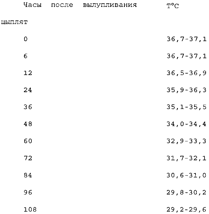
Также предпочтительно, что в инкубационной камере температуру устанавливают приблизительно 36,7-37,1°C и понижают приблизительно до 29,2-29,6°C приблизительно за 108 часов, при этом в инкубационной камере температуру изменяют, как показано в нижеприведенной таблице:It is also preferable that the temperature in the setter is set at approximately 36.7-37.1 ° C and lowered to approximately 29.2-29.6 ° C after approximately 108 hours, while the temperature in the setter is changed as shown in the table below. :
Предпочтительно все собранные яйца имеют вес меньше веса нормальных яиц, в частности вес составляет менее 50 г для бройлерных цыплят, в частности, вес составляет по меньшей мере 45 г для бройлерных цыплят.Preferably, all the eggs collected have a weight less than the weight of normal eggs, in particular the weight is less than 50 g for broiler chickens, in particular, the weight is at least 45 g for broiler chickens.
Предпочтительно, клетки имеют дно, выполненное в виде решетки, и биоразрушаемый лист, расположенный на поверхности решетки для обеспечения поверхности для хождения цыплят в течение первого и второго дней.Preferably, the cells have a bottom made in the form of a lattice and a biodegradable sheet located on the surface of the lattice to provide a surface for walking of chickens during the first and second days.
Также предпочтительно, поверхностный лист выполнен из по существу целлюлозного материала и предназначен для биологического разложения между первым и вторым днями после размещения цыплят в клетке.Also preferably, the surface sheet is made of essentially cellulosic material and is designed to biodegrade between the first and second days after the chicks are placed in the cage.
Согласно одному из аспектов изобретения решетка имеет отверстия с размерами, составляющими от около 0,7 до 1,2 см ×1,3-1,8 см, в частности, составляющими около 0,9-1,1× 1,4-1,6 см.According to one aspect of the invention, the grill has openings with dimensions ranging from about 0.7 to 1.2 cm × 1.3-1.8 cm, in particular from about 0.9-1.1 × 1.4-1 6 cm
Предпочтительно, клетки имеют кормушку, расположенную вдоль по меньшей мере одной из сторон клеток и снабженную поперечными стенками для обеспечения выхода цыплят с возрастом в 1-2 дня из кормушки.Preferably, the cells have a feeder located along at least one side of the cells and provided with transverse walls to allow chicks to reach 1-2 days of age from the feeder.
Сбор яиц первых 3-5 кладок молодых куриц осуществляют в возрасте 26 недель.The eggs of the first 3-5 clutches of young hens are collected at the age of 26 weeks.
Изобретение также относится к способу выращивания домашней птицы, выведенной в соответствии с вышеуказанным способом. Было обнаружено, что в данном варианте осуществления, в частности вследствие тщательного регулирования температуры, цыплята имеют, например, лучшие перья. Кроме того, климатическая камера WO 2009/014422 обеспечивает качественное регулирование окружающих условий инкубатора. Вследствие этого, в данном описании также будет сделана ссылка на инкубационную камеру. В частности было обнаружено, что это предоставляет возможность установки более низкой температуры в помещении для бройлерных цыплят на более поздней стадии. В частности, было возможно следующее регулирование температуры.The invention also relates to a method for growing poultry bred in accordance with the above method. It was found that in this embodiment, in particular due to careful temperature control, the chickens have, for example, better feathers. In addition, the climatic chamber WO 2009/014422 provides high-quality control of the ambient conditions of the incubator. Because of this, reference will also be made in this description to the incubation chamber. In particular, it was found that this provides the possibility of setting a lower temperature in the room for broiler chickens at a later stage. In particular, the following temperature control was possible.


В действительности было обнаружено, что вплоть до приблизительно 21-го дня температуру в помещении для бройлеров можно поддерживать до приблизительно 1-3 градусов ниже обычной температуры в помещении для бройлеров. В частности, в помещении для бройлеров обычно температуру снижают начиная с 4-го дня приблизительно на 0,5°C в день до приблизительно 20,5°C на 21-й день, а затем более медленно приблизительно до 17,5°C на 43-й день. В данном изобретении было обнаружено, что после использования инкубационной камеры в течение первых 4 дней после вылупления цыплят, температура может быть понижена до более чем на 1°C относительно обычной температуры. В частности, было обнаружено, что температура может быть понижена более чем на 1,5°C ниже обычной температуры. Было обнаружено, что температура может быть понижена даже более чем на 2°C ниже обычной температуры. Таким образом, цыплята согласно данному аспекту изобретения начинают развитие приблизительно при 30-33°C на 4-й день. В варианте осуществления, они начинают развитие при температуре, равной приблизительно 31-32°C. После этого температуру можно понижать ежедневно приблизительно до 19-22°С спустя 21 день. В частности, температуру снижают приблизительно до 20-21°C спустя 21 день. В действительности, обычно температуру снижают приблизительно на 0,5°C в день приблизительно до 20-21°C. In fact, it has been found that until about the 21st day, the temperature in the broiler room can be maintained up to about 1-3 degrees below the usual temperature in the broiler room. In particular, in the broiler room, the temperature is usually lowered from day 4 by approximately 0.5 ° C per day to approximately 20.5 ° C on
Необходимо заметить, что показания температуры для помещения для бройлеров являются менее точными, чем в инкубационной камере. В помещении для бройлеров климатические условия поддерживать более тяжело. Могут иметься различия в температуре от одного места около пола в помещении для бройлеров до следующего места около пола в помещении для бройлеров. Квалифицированный специалист будет в состоянии, на основании информации в данном документе, оценить как использовать изобретение. При использовании инкубационной камеры было обнаружено, что после вылупления цыплята лучше развиваются в течение следующих 4-10 дней, в варианте осуществления в течение 3-5 дней, в частности в течение приблизительно 4 дней. Со всех сторон у цыплят лучше развиваются перья. Таким образом, было обнаружено, что это предоставляет возможность поддержания температур в помещениях для бройлерных цыплят ниже, чем обычно, экономя таким образом, например, на затратах на обогрев. В действительности, повышение температуры до обычных уровней может даже приводить к перегреву цыплят.It should be noted that the temperature readings for the broiler room are less accurate than in the incubation chamber. In a broiler room, climatic conditions are more difficult to maintain. There may be differences in temperature from one place near the floor in the broiler room to the next place near the floor in the broiler room. A qualified person will be able, based on the information in this document, to evaluate how to use the invention. Using an incubation chamber, it was found that after hatching, the chickens develop better over the next 4-10 days, in an embodiment within 3-5 days, in particular within about 4 days. Feathers develop better on all sides of chickens. Thus, it was found that this provides the opportunity to maintain the temperature in the premises for broiler chickens lower than usual, thus saving, for example, the cost of heating. In fact, raising the temperature to normal levels can even lead to overheating of the chickens.
Согласно этому способу осуществляют следующие этапы:According to this method, the following steps are carried out:
размещение цыплят непосредственно после их вылупливания из яиц в клетки по 10-500 цыплят;placement of chickens immediately after hatching from eggs into cages for 10-500 chickens;
расположение клеток в штабелях в инкубационной камере;the location of cells in piles in the incubation chamber;
подача корма и питья в каждую клетку в инкубационной камере иfeed and drink to each cell in the incubation chamber and
регулирование температуры, влажности, концентрации CO2 и скорости потока воздуха в инкубационной камере и содержание цыплят до 4-10 дней после их вылупления из яиц, в частности приблизительно 3-5 дней, в инкубационной камере;control of temperature, humidity, CO 2 concentration and air flow rate in the incubation chamber and keeping the chickens up to 4-10 days after hatching from eggs, in particular about 3-5 days, in the incubation chamber;
перемещение цыплят из инкубационной камеры в помещение для бройлерных цыплят.moving chickens from the incubation chamber to the broiler chickens.
В помещении для бройлерных цыплят температуру поддерживают до более чем на 1°C ниже, чем обычная температура, в частности более чем на 1,5°C ниже обычной температуры, в частности более чем на 2°C ниже обычной температуры.In the broiler chickens room, the temperature is maintained up to more than 1 ° C lower than normal temperature, in particular more than 1.5 ° C lower than normal temperature, in particular more than 2 ° C lower than normal temperature.
Предпочтительно, чтобы температура в помещении для бройлерных цыплят начиналась приблизительно при 30-33°C, в частности с 31-32°C, в частности на уровне указанных цыплят.Preferably, the temperature in the room for broiler chickens began at approximately 30-33 ° C, in particular from 31-32 ° C, in particular at the level of these chickens.
Также предпочтительно снижать температуру ежедневно, приблизительно до около 19-22°C спустя 21 день, в частности приблизительно до 20-21°C спустя 21 день, в частности температура снижается приблизительно на 0,5°C в день приблизительно до 20-21°C.It is also preferable to lower the temperature daily, to about 19-22 ° C after 21 days, in particular to about 20-21 ° C after 21 days, in particular the temperature drops by about 0.5 ° C per day to about 20-21 ° C.
Предпочтительно после вылупления из яиц цыплят содержат в инкубационной камере при температуре, начиная приблизительно с 36,6-37,2°C, в частности с 36,8-37,0°C, в частности указанная температура снижается приблизительно до 28,0-28,6°C, в частности до 28,1-28,5°C, при этом указанная температура снижается приблизительно с линейной скоростью.Preferably, after hatching from eggs, the chickens are kept in an incubation chamber at a temperature starting from about 36.6-37.2 ° C, in particular from 36.8-37.0 ° C, in particular, the temperature decreases to about 28.0- 28.6 ° C, in particular to 28.1-28.5 ° C, while the indicated temperature decreases at approximately linear speed.
Изобретение дополнительно относится к оборудованию, содержащему один или более отличительных признаков, описанных в описании и/или показанных на приложенных чертежах. Кроме того, изобретение относится к способу, включающему один или более отличительных признаков, описанных в описании и/или показанных на приложенных чертежах.The invention further relates to equipment containing one or more of the distinguishing features described in the description and / or shown in the attached drawings. In addition, the invention relates to a method comprising one or more of the distinguishing features described in the description and / or shown in the attached drawings.
Различные аспекты, обсуждаемые в данном патенте, могут быть объединены для обеспечения дополнительных преимуществ. Кроме того, некоторые признаки могут сформировать основу для одной или более выделенных заявок.Various aspects discussed in this patent can be combined to provide additional benefits. In addition, some features may form the basis for one or more highlighted applications.
ОПИСАНИЕ ЧЕРТЕЖЕЙDESCRIPTION OF DRAWINGS
Представленное изобретение в частности использует климатическую камеру или инкубационную камеру, раскрытую в публикации WO-2009/014422, в частности модифицированную для данного способа с целью выращивания цыплят после того, как они вылупились из яиц, описанную ниже более подробно со ссылкой на пример, схематично проиллюстрированный на чертежах, на которых показано следующее:The presented invention in particular uses a climate chamber or an incubation chamber disclosed in publication WO-2009/014422, in particular modified for this method to grow chickens after they hatched from eggs, described in more detail below with reference to an example, schematically illustrated in the drawings, which show the following:
Фиг. 1 показывает перспективный вид теплообменника согласно изобретению,FIG. 1 shows a perspective view of a heat exchanger according to the invention,
Фиг. 2 показывает перспективный вид в поперечном разрезе части теплообменника на Фиг. 1,FIG. 2 shows a perspective cross-sectional view of a portion of the heat exchanger of FIG. one,
Фиг. 3 показывает вид сбоку в поперечном разрезе части теплообменника на Фиг. 1 вместе с частью штабеля клеток,FIG. 3 shows a cross-sectional side view of a portion of the heat exchanger of FIG. 1 along with part of the cell stack,
Фиг. 4 показывает схематичный вид сверху климатической камеры согласно изобретению,FIG. 4 shows a schematic top view of a climate chamber according to the invention,
Фиг. 5 показывает вертикальный вид в продольном сечении климатической камеры вдоль стрелок V на Фиг. 4,FIG. 5 shows a vertical longitudinal sectional view of the climate chamber along arrows V in FIG. four,
Фиг. 6 показывает перспективный вид клетки из штабеля клеток, который проиллюстрирован на Фиг. 3,FIG. 6 shows a perspective view of a cell from a stack of cells, which is illustrated in FIG. 3
Фиг. 7 показывает первый вертикальный вид в продольном сечении клетки вдоль стрелок VII на Фиг. 6, FIG. 7 shows a first vertical view in longitudinal section of a cell along arrows VII in FIG. 6
Фиг. 8 показывает второй вертикальный вид в продольном сечении клетки вдоль стрелок VIII на Фиг. 6.FIG. 8 shows a second vertical view in longitudinal section of the cell along arrows VIII in FIG. 6.
ПОДРОБНОЕ ОПИСАНИЕ ВАРИАНТОВ ОСУЩЕСТВЛЕНИЯDETAILED DESCRIPTION OF EMBODIMENTS
Непосредственно после вылупления из яиц цыплят предпочтительно растят в климатической камере или инкубационной камере описанного ниже типа. Сначала описан теплообменник для подобной камеры. В варианте осуществления, она имеет желоба для подачи питья цыплятам и может иметь встроенное освещение. Цыплята находятся в климатической камере, снабженной штабелями клеток, описанными в дальнейшем в данном описании. Данные клетки были модифицированы для размещения цыплят молодых куриц возрастом менее 29 недель. Обычно, курицами становятся приблизительно с 26-недельного возраста. Первые 3-5 кладок яиц таких куриц составляют приблизительно только 45-50 г. Было обнаружено, что особые регулируемые условия в климатической камере или инкубационной камере, дополнительно описанные ниже, предоставляют возможность выведения особых цыплят рентабельным способом.Immediately after hatching from the eggs, the chickens are preferably raised in a climate chamber or incubation chamber of the type described below. First, a heat exchanger for a similar chamber is described. In an embodiment, it has chutes for supplying drink to chickens and may have built-in lighting. The chickens are located in a climatic chamber equipped with stacks of cells described later in this description. These cells were modified to accommodate young chickens less than 29 weeks old. Usually, hens become approximately 26 weeks old. The first 3-5 egg laying of such hens is approximately only 45-50 g. It was found that the special regulated conditions in the climate chamber or incubation chamber, further described below, provide the opportunity to breed special chickens in a cost-effective way.
Фиг. 1, 2 и 3 показывают теплообменник для использования в климатической камере. Данный теплообменник расположен вокруг панелеобразного корпуса 21, имеющего одну или более трубок 22 для текучей среды. Панелеобразный корпус 21 снабжен перфорационными отверстиями 25 и 26. Данные перфорационные отверстия обеспечивают возможность прохождения газовой струи, показанной стрелкой А, через панелеобразный корпус 21 в направлении, поперечном панелеобразному корпусу 21. По аналогии с радиатором, панелеобразный корпус 21 может быть доведен до конкретной температуры посредством текучей среды, протекающей через одну или более трубок для текучей среды. Одна или более трубок для текучей среды расположены между подающей трубкой и выпускной трубкой для указанной текучей среды. Панелеобразный корпус и трубки для текучей среды обычно изготовлены из металла и образуют друг с другом единую деталь, например, посредством приваривания друг к другу, припаивания друг к другу или за счет экструзионного прессования трубок и корпуса в течение одной операции с образованием единого экструзионного профиля. Подобный теплообменник, который описан выше со ссылкой на фиг. 1, 2 и 3, показан на фиг. 3 и 4 публикации WO 00/08922. Согласно изобретению данный известный теплообменник дополнительно снабжен, в частности, газовыми воздуховодами 28.FIG. 1, 2 and 3 show a heat exchanger for use in a climate chamber. This heat exchanger is located around the panel-shaped
Газовые воздуховоды 28 расположены параллельно друг другу и вдоль панелеобразного корпуса 21. Газовые воздуховоды 28 снабжаются с помощью одного или более воздуховодов 27 для подачи среды и соединены с ними проходными отверстиями 34. Как показано на Фиг. 1, трубчатый воздуховод 27 для подачи среды расположен вдоль противоположных сторон панелеобразного корпуса 21, так что газовые воздуховоды 28 могут снабжаться средой одновременно с двух сторон. Газовые воздуховоды 28 проходят между последними и поперек воздуховодов 27 для подачи среды. Газовые воздуховоды 28 расположены с межцентровым расстоянием С друг от друга таким образом, чтобы в каждом случае одна промежуточная зона 39 панелеобразного корпуса 21 остается чистой между двумя газовыми воздуховодами 28, расположенными один над другим. Высота В данной промежуточной зоны 39 может составлять, например, от 7 до 10 см, например, приблизительно 8,5 см в данном варианте осуществления. Газовая струя А может проходить через панелеобразный корпус 21 через перфорационные отверстия 25 в данной промежуточной зоне 39.The
Каждый газовый воздуховод 28 имеет внутреннюю часть 29, которая ограничена верхней стенкой 35, нижней стенкой 37 и двумя боковыми стенками 36. Панелеобразный корпус 21 в каждом случае проходит через газовый воздуховод 28 деталью 30, которая фактически образует перегородку, которая делит газовый воздуховод 28 на первое отделение 32 воздуховода и второе отделение 33 воздуховода. Оба отделения проходят вдоль всей длины газового воздуховода 28, и в данном случае имеют одинаковые размер и форму. Однако отделения воздуховода не должны иметь одинаковые размер и форму. Также допускается, чтобы имелось только одно отделение, например, если панелеобразный корпус ограничивает боковую стенку газового воздуховода, например, если деталь 30 была исключена или если газовый воздуховод был помещен напротив или близко к панелеобразному корпусу снаружи от панелеобразного корпуса.Each
Для обеспечения выхода среды, подаваемой через газовые воздуховоды 28, вдоль панелеобразного корпуса 21 и ее распределения в окружающей области, в частности направления поперек панелеобразного корпуса 21, каждый газовый воздуховод 28 снабжен выпускными отверстиями 31, расположенными по длине газового воздуховода рассредоточенным образом. За счет изменения размера данных выпускных отверстий 31 и/или расстояния между соседними выпускными отверстиями 31 может быть получена равномерная доставка вдоль всей длины газового воздуховода 28. In order to ensure that the medium supplied through the
В варианте осуществления, проиллюстрированном на фиг. 1, 2 и 3, в каждом случае только второе отделение 33 воздуховода снабжено выпускными отверстиями 31, а первое отделение воздуховода является по существу закрытым за исключением проходных отверстий 34 и перфорационных отверстий 26. Преимущество этого состоит в том, что подаваемая среда распространяется по длине газового воздуховода в первом отделении, при этом температура испытывает воздействие (а именно повышается или понижается) температуры детали 30 панелеобразного корпуса, причем данная деталь действует в качестве перегородки, затем среда проходит во второе отделение через перфорационные отверстия 26 в указанной детали 30, которая действует в качестве перегородки, при этом температура среды снова испытывает воздействие, а среда проходит в выпускные отверстия через второе отделение, при этом температура среды в данном случае снова также в это время испытывает воздействие.In the embodiment illustrated in FIG. 1, 2 and 3, in each case only the
Воздуховоды 27 для подачи среды расположены вдоль противоположных кромок панелеобразного корпуса 21 и прикреплены к нему. Таким образом, теплообменник может быть выполнен в виде модульного блока, в котором при установке необходимо соединить только два воздуховода для подачи среды. Кроме того, внутри воздуховодов для подачи среды помещены подающая трубка 23 и выпускная трубка 24 для текучей среды. На практике, это может быть достигнуто относительно легко по существу без необходимости увеличения размеров воздуховодов для подачи среды. В конце концов, текучей средой обычно бывает такая текучая среда, как вода, так что данные трубки 23 и 24 могут быть относительно небольшими, по сравнению с трубопроводом для подачи газовой среды. Еще одним преимуществом является то, что воздуховод для подачи среды таким образом защищает трубку 23 и/или 24 от повреждения, и на температуру среды может быть при необходимости оказано воздействие и за счет нагревания или охлаждения посредством трубки 23 и/или 24, когда среда проходит/протекает по воздуховоду для подачи среды.
Как показано на фиг. 2 и 3, внутренняя часть 29 каждого газового воздуховода 28 соприкасается с внутренней частью 38 трубки 22 для текучей среды как на верхней стенке 35, так и на нижней стенке 37. Это улучшает теплообмен между текучей средой и средой.As shown in FIG. 2 and 3, the
Согласно дополнительному варианту осуществления каждый газовый воздуховод 28 теплообменника 1 согласно изобретению снабжен желобом 40, имеющим первый конец 41 и второй конец 42. Данные желобы 40 могут быть использованы для увлажнения за счет наполнения их жидкостью, в частности водой, и обеспечения возможность ее испарения. При использовании в климатической камере для содержания птиц, данные желобы 40 также могут быть использованы в качестве поилок. Для того чтобы упростить наполнение желобов 40 жидкостью, последние, в частности, снабжают водовыпуском 43 рядом со вторым концом, а желоба располагают уступами друг над другом, причем в каждом случае второй конец 42 желоба 40 расположен на более высоком уровне над первым концом 41 желоба 40, расположенного на более низком уровне. Тогда жидкость может подаваться на первом конце 41 верхнего желоба, затем будет наполнять верхний желоб до уровня наполнения, определяемого водовыпуском, вслед за этим будет наполнять желоб, расположенный ниже, до уровня наполнения, определяемого его водовыпуском, и так далее, до тех пор, пока также не будет наполнен нижний желоб. С целью обеспечить, чтобы жидкость текла в каждый последующий желоб и для предотвращения запруживания, в случае, когда в одном желобе существует препятствие, первый продольный верхний край 44 желоба является более высоким, чем второй продольный верхний край 45 желоба, который находится более близко к панелеобразному корпусу 21, а верхняя стенка 35 газового воздуховода 28 в каждом случае продолжается до второго продольного верхнего края 45 желоба. Тогда жидкость может преодолевать препятствие через верхнюю стенку 35.According to a further embodiment, each
Как показано на фиг. 2 и 3, каждый газовый воздуховод дополнительно снабжен, при необходимости, крепежным средством, например принимающим пазом 46, для крепления осветительного прибора 47 (проиллюстрированного только на фиг. 2). Данный прибор 47 снабжен рядом, содержащим множество осветительных светоизлучающих диодов (СИД) 48, 49. В данном случае, несколько СИД 49 в каждом случае направлены в сторону желоба 40 внизу (направленная стрелка 80 на фиг. 2) для того, чтобы освещать последний. Автор заявки обнаружил, что если желоба 40 представляют собой поилки для домашней птицы, в частности для цыплят, предпочтительным является, если данные СИД излучают красный свет. Тогда птицы могут легко найти поилку. Другие СИД 48 могут быть направлены в различных направлениях (направленные стрелки 81 и 82 на фиг. 2) для того, чтобы обеспечить равномерное освещение и предотвратить ослепление птиц.As shown in FIG. 2 and 3, each gas duct is further provided, if necessary, with fixing means, for example, a receiving
Теплообменник 1 согласно изобретению предпочтительным образом может быть использован в климатической камере, в частности в климатической камере для цыплят, в частности очень молодых цыплят, например цыплят возраста менее 4 дней или возраста 0 или 1 дня. Подобные цыплята еще не способны очень хорошо регулировать температуру своего собственного тела. Для того чтобы хорошо их выращивать, важно содержать их при предварительно заданной температуре, которая зависит от типа цыплят, в частности во время первоначальной фазы после вылупления из яиц, и регулировать данную температуру очень точно (а именно с точностью, равной ±1°C, предпочтительно с точностью, равной ±0,5°C, или с большей точностью, например ±0,2°C или меньше). The heat exchanger 1 according to the invention can advantageously be used in a climate chamber, in particular in a climate chamber for chickens, in particular very young chickens, for example chickens less than 4 days old or 0 or 1 day old. Such chickens are not yet able to regulate the temperature of their own body very well. In order to grow them well, it is important to keep them at a predetermined temperature, which depends on the type of chickens, in particular during the initial phase after hatching from the eggs, and to regulate this temperature very accurately (namely, with an accuracy of ± 1 ° C, preferably with an accuracy of ± 0.5 ° C, or with greater accuracy, for example ± 0.2 ° C or less).
Согласно изобретению термин климатическая камера является устройством, имеющим внутреннее пространство, которое может регулировать температуру во всем данном внутреннем пространстве с точностью, равной ±1°C, предпочтительно с точностью, равной ±0,5°C, или с большей точностью, например ±0,2°C или менее (другими словами, наибольшее отличие в температуре между двумя точками в указанном пространстве будет не больше, чем значение указанной ′точности′).According to the invention, the term climate chamber is a device having an internal space that can regulate the temperature in the entire given internal space with an accuracy of ± 1 ° C, preferably with an accuracy of ± 0.5 ° C, or with greater accuracy, for example ± 0 , 2 ° C or less (in other words, the greatest difference in temperature between two points in the specified space will be no more than the value of the specified 'accuracy').
Фиг. 4 и 5 очень схематично показывают подобную климатическую камеру 3, которая, в частности в данном случае, предназначена для выведения цыплят, которые только что вылупились. Данная климатическая камера ограничена снаружи теплоизолированными боковыми стенками 14, теплоизолированным потолком 16 и полом 15, который предпочтительно также теплоизолирован. Климатическая камера 3 имеет по меньшей мере одно отделение 4 камеры, в котором цыплята содержатся в кондиционированных окружающих условиях. В проиллюстрированном примере имеется два ряда, каждый с пятью отделениями 4 камеры. Ряды расположены по обеим сторонам коридора 5 и доступны из коридора 5 через двери 9. Вход и выход из климатической камеры 3 возможен посредством по меньшей мере одной двери 10, 11. В данном примере, на одном конце коридора предоставлена дверь 10, которая предназначена в частности для входа в коридор 5 климатической камеры, а на другом конце предоставлена дверь 11, которая предназначена в частности для выхода из коридора 5 климатической камеры.FIG. 4 and 5 very schematically show a similar
На одном конце каждого ряда отделений 4 камеры в каждом случае размещена впускная камера 13 для впуска кондиционированного газа, например воздуха, в расположенное выше по движению газа отделение 4 камеры, а на другом конце каждого ряд отделений 4 камеры в каждом случае предоставлена выпускная камера 13 для сбора газа, выходящего из расположенного ниже по движению газа отделения 4 камеры. Хотя это не требуется, энергетически предпочтительно впоследствии подавать газ из выпускной камеры 13 назад во впускную камеру. Газ может подаваться назад поверх отделений камеры, как проиллюстрировано в публикации WO 00/08922. Однако данный способ требует много пространства и более предпочтительно подавать газ назад через коридор 5, как показано на фиг. 4 посредством стрелки G. Это ведет к значительному снижению объема требуемого пространства. В дополнение, еще одним результатом является то, что коридор 5 также кондиционируется, хотя и немного менее хорошо, чем отделения 3 камеры, так что в процессе использования есть возможность открывать дверь 9 отделения камеры, вызывая в то же время минимальное нарушение климата.At each end of each row of chamber compartments 4, in each case, an
На фиг. 4 направление транспортировки продуктов, подлежащих обработке в климатической камере, например цыплят, обозначено посредством стрелки K. Продукты предпочтительно выгружают через дверь 11 и подают через дверь 10, 11, поскольку таким образом сторона подачи может сохраняться относительно чистой, что предотвращает загрязнение.In FIG. 4, the conveying direction of the products to be processed in the climate chamber, such as chickens, is indicated by arrow K. The products are preferably unloaded through the door 11 and fed through the
Отделения данной климатической камеры снабжены на противоположных сторонах теплообменниками. Сторона поступления отделения камеры, которая расположена наиболее высоко по движению газа, в каждом случае ограничена теплообменником 7, сторона выхода наиболее низкого по движению газа отделения камеры в каждом случае ограничена теплообменником 8, а смежные отделения камеры в каждом случае ограничены друг относительно друга теплообменником 1. Данные теплообменники 1, 7 и 8 могут быть по существу идентичны друг другу, но принимая во внимание факт, что теплообменники 7 и 8 ограничивают отделение камеры только с одной стороны, квалифицированным специалистам в данной области должно быть понятно, что данные теплообменники 7 и 8 также могут быть различной конструкции, в частности на стороне, которая удалена от отделения 4 камеры. Теплообменники 1, 7 и 8 относятся к типу, который состоит из панелеобразного корпуса 21, снабженного перфорационными отверстиями 25 и 26, а также трубок 22 для текучей среды. Газовая струя через отделения камеры и перфорационные отверстия в панелеобразном корпусе 21 в данном случае обозначена посредством стрелок L. Вентиляционные средства 50, например вентиляторы, в данном случае, обеспечивают поддержку газовой струи. В силу этого данные вентиляционные средства могут быть предоставлены в различных местоположениях, но, как правило, будут предоставлены во впускной камере 12 и/или выпускной камере 13.The compartments of this climate chamber are equipped on opposite sides with heat exchangers. The entry side of the chamber compartment, which is located highest in the gas movement, in each case is limited by the
Что касается климатической камеры, которая описана до сих пор со ссылкой на Фиг. 4 и 5, отсутствует жесткая необходимость снабжения теплообменника газовыми воздуховодами, хотя это имеет суммарное преимущество.With regard to the climate chamber, which is still described with reference to FIG. 4 and 5, there is no strict need to supply the heat exchanger with gas ducts, although this has a cumulative advantage.
Как изложено выше, климатическая камера 3 согласно изобретению в частности снабжена теплообменниками 1, 7 и 8, которые описаны в различных дополнительных вариантах осуществления со ссылкой на фиг. 1, 2 и 3. В каждом отделении камеры расположены 1, 2, 3 или более рядов 6 штабелированных клеток 2. В частности, это 1 или 2 рядов штабелей, например, два ряда 6 штабелей, как схематично проиллюстрировано в центральном отделении камеры на фиг. 5. В зависимости от глубины каждого отделения 4 камеры, если смотреть под прямыми углами к плоскости чертежа на Фиг. 5, и длины, если смотреть в направлении двойной стрелки М на Фиг. 6, каждый ряд 6 штабелей клеток может содержать один или более штабелей клеток.As described above, the
Как показано на фиг. 6, 7, 8 и 3, если теплообменники 1, 7 и 8 снабжены поилками 40, каждая клетка предпочтительно имеет высоту Н, соответствующую межцентровому расстоянию С между газовыми воздуховодами 28 и поилками 40. Кроме того, клетка 2 снабжена поильными проходами 54 с одной стороны, стороны, обращенной к поилке 40, для того чтобы птицы, в частности цыплята, могли пить из желоба 40. Данные поильные проходы 54 могут быть расположены в вертикальной боковой стенке клетки. Однако особенно предпочтительно обеспечить, чтобы сторона клетки 2 была обращена к поилке, начиная с низу, нижней частью 51 вертикальной стенки, частью 52 стенки, которая направлена наружу от верха нижней части 51 вертикальной стенки, и верхней частью 53 стенки, которая направлена вертикально от наружной кромки направленной наружу части 52 стенки. Направленная наружу часть 52 стенки каждой клетки 2 в каждом случае расположена над желобом 40 и снабжена поильными проходами 54, которые продолжаются насколько можно в нижнюю часть 51 вертикальной стенки для повышения удобства питья. As shown in FIG. 6, 7, 8 and 3, if the
Размеры данных поильных проходов 54 подобраны, с одной стороны, таким образом, чтобы птицы могли пить из поилки, но, с другой стороны, не могли убежать из клетки 2 через поильный проход 54. Ширина Е поильных проходов составляет в данном случае приблизительно 22 мм, так что цыплята могут просовывать через них свои головы, но их тело является слишком большим для прохода через них. Нижняя часть 51 вертикальной стенки образует разновидность ограждения, которое мешает цыплятам толкать друг друга до самого верха желоба и обеспечивает правильный питьевой уровень. В качестве ориентира, для петушков или курочек, нижняя часть 51 вертикальной стенки, в данном случае, может иметь высоту, равную приблизительно от 50 мм до 55 мм, а верхняя часть 53 вертикальной стенки в данном случае может иметь высоту, составляющую приблизительно от 90 мм до 110 мм.The dimensions of these
Для прохождения газовой струи А в клетку 2 клетка 2 снабжена вентиляционными отверстиями с двух противоположных сторон, которые находятся под прямыми углами к газовой струе А, для обеспечения прохождения газовой струи А. Данные вентиляционные каналы имеют ширину F (Фиг. 7), которая является такой, чтобы цыплята не могли через них убежать. Ширина F предпочтительно такова, чтобы цыплята не могли высовывать свои головы из клетки.For the passage of the gas stream A into the
Для обеспечения кормления птиц, например упомянутых выше цыплят, клетка 2 снабжен кормушкой 60. Для обеспечения прохождения газа через клетку 2 наиболее беспрепятственным способом данная кормушка 60 расположена вдоль стороны клетки 2, которая находится под прямыми углами к стороне, вдоль которой расположена поилка 40, по меньшей мере поильные проходы 54. Кормушка 60 содержит перегородку 62, которая отделяет загрузочное отверстие 61 от приемного отверстия 63, которое расположено на более низком уровне. Приемное отверстие 63 данного варианта осуществления снабжено элементами, поперечными направлению приемного отверстия 63 кормушки 61. Таким образом, очень небольшим и очень молодым цыплятам будет предоставлена возможность выбираться из приемного отверстия 63. В варианте осуществления, в указанной кормушке будут размещены с промежутками поперечные стенки. Данные стенки не обозначены на чертеже. Стенки обычно имеют интервал, равный приблизительно 2-4 см.To ensure the feeding of birds, for example, the chicks mentioned above,
Согласно дополнительному аспекту изобретения дно клеток выполнено в виде решетки 56 со съемным поддоном 55, вставляемым снизу. Данный поддон предпочтительно изготавливают из материала, имеющего в своем составе целлюлозу, например картона. Поддон 55 может быть переработан и утилизирован вместе с пометом в качестве изделия разового пользования. В более общем смысле, предпочтительным является, если поддон изготовлен из биоразрушаемого материала, например биоразрушаемой пластмассы или биоразрушаемого картона. Данный поддон 55, в частности, расположен на расстоянии D, составляющем от 5 мм до 50 мм, под решеткой 56. Как показано на Фиг. 8, данный поддон 55 может устанавливаться в клетку и удаляться из клетки за счет скольжения, как показано двойной стрелкой N. С этой целью клетка 2 снабжена двумя ребрами 65 и 66 на обратной стороне, между которыми имеется паз, в котором могут помещаться противоположные кромки поддона. При штабелировании опоры 67 клетки 2 снизу в каждом случае обеспечивают поддержку поддона 55 клетки 2 выше. Обратная сторона решетки отдельно выполнена в виде выпуклости вверх. Для того чтобы была возможность безопасно перемещать данную клетку 2 на ленте транспортера без поддона 55, но с цыплятами 100 или другими птицами, не повреждая ноги или пальцы птиц, предпочтительным является, если клетка 2 снабжена на обратной стороне опорными ножками 58, которые обеспечивают наличие минимального расстояния D, составляющего от 5 до 15 мм, между обратной стороной решетки 56 и поверхностью. Для того чтобы предотвратить прогибание решетки, ее снабжают на обратной стороне ребрами 59 жесткости.According to an additional aspect of the invention, the bottom of the cells is made in the form of a
В частности, в данном изобретении поверхностный слой листа из биоразрушаемого материала расположен поверх решетки 56. Так как цыплята согласно данному изобретению сразу после вылупления из яиц в первый и иногда даже во второй день очень маленькие, их ноги могут застревать в решетках 56. Поверхностный лист будет оставаться настолько долго, насколько надо для предотвращения проблем. Пространство между решетками 56 не должно быть слишком маленьким, так как в противном случае через него не будет падать помет птиц.In particular, in the present invention, the surface layer of the biodegradable material sheet is located on top of the
Необходимо заметить, что штабель клеток для молодых птиц, таких как цыплята, описанный в данном абзаце, сам по себе образует дополнительное изобретение, на которое заявитель резервирует все права. Данное дополнительное изобретение, независимо всего остального, что было описано в данной заявке относительно клетки, может быть охарактеризовано, как штабель, содержащий множество клеток, необязательно заключающих в себе птиц, например, цыплят, при этом каждая клетка имеет дно, выполненное в виде решетки 56, имеющей съемный поддон 55, вставляемый снизу для сбора помета. Дополнительное изобретение, кроме того, относится к отдельной клетке, которая описана выше в данном абзаце. Как изложено выше, заявитель резервирует все права относительно подобного штабеля клеток и относительно подобной отдельной клетки, например права для подачи выделенной патентной заявки.It should be noted that the stack of cages for young birds, such as chickens, described in this paragraph, in itself forms an additional invention, to which the applicant reserves all rights. This additional invention, independently of everything else that has been described in this application regarding the cell, can be characterized as a stack containing many cells, optionally containing birds, for example, chickens, with each cell having a bottom made in the form of a
Также должно быть ясно, что описание и чертежи выше включены для иллюстрирования некоторых вариантов осуществления изобретения, а не для ограничения объема правовых притязаний. Исходя из данного описания, квалифицированным специалистам очевидны множество вариантов осуществления, которые находятся в пределах объема правовых притязаний и сущности данного изобретения и которые представляют собой явные комбинации технологий предыдущего уровня техники и настоящей заявки.It should also be clear that the description and drawings above are included to illustrate some embodiments of the invention, and not to limit the scope of legal claims. Based on this description, qualified specialists will recognize many embodiments that are within the scope of the legal claims and the essence of this invention and which are explicit combinations of prior art technologies and the present application.
СПИСОК ССЫЛОЧНЫХ НОМЕРОВLIST OF REFERENCE NUMBERS
1 - теплообменник1 - heat exchanger
2 - клетка2 - cell
3 - климатическая камера3 - climate chamber
4 - отделение (камеры) в климатической камере4 - compartment (cameras) in the climate chamber
5 - коридор в климатической камере5 - corridor in the climate chamber
6 - штабель клеток6 - cell stack
7 - теплообменник7 - heat exchanger
8 - теплообменник8 - heat exchanger
9 - дверь9 - door
10 - дверь10 - door
11 - дверь11 - door
12 - впускная камера12 - inlet chamber
13 - выпускная камера13 - exhaust chamber
14 - вертикальная наружная стенка климатической камеры14 - vertical outer wall of the climate chamber
15 - пол климатической камеры15 - floor climate chamber
16 - потолок климатической камеры16 - ceiling climate chamber
21 - панелеобразный корпус21 - panel-shaped housing
22 - трубка для текучей среды22 - fluid pipe
23 - подающая трубка для текучей среды23 - fluid supply pipe
24 - выпускная трубка для текучей среды24 - fluid outlet pipe
25 - перфорационное отверстие25 - perforation hole
26 - перфорационное отверстие26 - perforation hole
27 - воздуховод для подачи среды27 - duct for supplying medium
28 - газовый воздуховод28 - gas duct
29 - внутренняя часть газового воздуховода29 - the inner part of the gas duct
30 - часть панелеобразного корпуса, соприкасающаяся с внутренней частью газового воздуховода30 - part of the panel-shaped housing in contact with the inner part of the gas duct
31 - выпускное отверстие31 - outlet
32 - первое отделение воздуховода32 - the first section of the duct
33 - второе отделение воздуховода33 - the second compartment of the duct
34 - проходное отверстие из воздуховода для подачи среды в первое отделение воздуховода34 - passage hole from the duct for supplying medium to the first compartment of the duct
35 - верхняя стенка первого и второго отделения воздуховода35 - upper wall of the first and second compartment of the duct
36 - боковая стенка первого/второго отделения воздуховода36 - side wall of the first / second compartment of the duct
37 - нижняя стенка первого и второго отделения воздуховода37 - bottom wall of the first and second compartment of the duct
38 - наружная поверхность трубки для текучей среды38 - the outer surface of the tube for the fluid
39 - промежуточная зона панелеобразного корпуса, расположенная между газовыми воздуховодами39 - the intermediate zone of the panel-shaped housing located between the gas ducts
40 - желоб40 - gutter
41 - первый конец желоба41 - the first end of the gutter
42 - второй конец желоба42 - the second end of the gutter
43 - переток43 - overflow
44 - первый продольный край желоба44 - the first longitudinal edge of the gutter
45 - второй продольный край желоба45 - the second longitudinal edge of the gutter
46 - паз для крепления осветительного прибора46 - groove for mounting the lighting device
47 - осветительный прибор47 - lighting device
48 - СИД48 - LED
49 - СИД, направленный на желоб49 - LED aimed at the gutter
50 - вентиляционное средство50 - ventilation means
51 - нижняя вертикальная часть стенки51 - lower vertical part of the wall
52 - направленная наружу часть стенки52 - outward directed part of the wall
53 - верхняя вертикальная часть стенки53 - upper vertical part of the wall
54 - (питьевой) проход54 - (drinking) passage
55 - поддон55 - pallet
56 - решетка56 - grill
57 - верхняя сторона/обратная сторона решетки/поддона57 - upper side / reverse side of the grill / pallet
58 - опорная ножка58 - supporting leg
59 - опорная ножка59 - supporting leg
60 - кормушка60 - feeding trough
61 - наполняющее отверстие кормушки61 - filling hole of the feeder
62 - перегородка кормушки62 - partition feeders
63 - приемное отверстие кормушки63 - receiving hole of the feeder
64 - вентиляционный проход64 - ventilation passage
65 - ребро65 - rib
66 - ребро66 - rib
67 - опора67 - support
100 - цыпленок100 - chicken
А - газовая струяA - gas jet
В - расстояние между газовыми воздуховодамиB is the distance between the gas ducts
С - межцентровое расстояние между газовыми воздуховодамиC - center-to-center distance between gas ducts
D - промежуточное пространство между поддоном и решеткойD - the intermediate space between the pallet and the grill
Е - ширина поильного проходаE - width of the watering passage
F - ширина вентиляционного проходаF - width of the ventilation passage
G - стрелки, показывающие обратную подачу газовой струиG - arrows showing the reverse flow of the gas stream
Н - высота клеткиH - cell height
K - стрелки, показывающие направление перемещения продуктовK - arrows showing the direction of movement of products
L - стрелки, показывающие газовую струю через отделения камеры и перфорационные отверстия в теплообменникеL - arrows showing the gas stream through the chamber compartments and perforations in the heat exchanger
М - двойная стрелка, показывающая продольное направление клеткиM - double arrow showing the longitudinal direction of the cell
N - двойная стрелка, показывающая скольжение поддона внутрь/наружуN - double arrow showing the pan sliding in / out
Claims (17)
сбор яиц первых 3-5 кладок молодых куриц моложе 28 недель;
содержание в инкубаторе собранных яиц и одновременное появление из них вылупившихся цыплят;
размещение вылупившихся цыплят в клетки по 10-500 цыплят непосредственно после их вылупления из яиц;
расположение клеток в штабелях в инкубационной камере;
подача корма и питья в каждую клетку в инкубационной камере,
регулирование температуры, влажности, концентрации CO2 и скорости потока воздуха в инкубационной камере,
причем температуру в инкубационной камере устанавливают приблизительно на 1-3°С выше температуры, установленной для цыплят, которые вылупляются из нормальных яиц.1. A method of breeding poultry offspring, containing the following stages:
egg collection of the first 3-5 clutches of young hens under 28 weeks of age;
keeping the collected eggs in the incubator and the simultaneous appearance of hatched chickens from them;
placement of hatched chickens in cages of 10-500 chickens immediately after hatching from eggs;
the location of cells in piles in the incubation chamber;
feed and drink to each cell in the incubation chamber,
regulation of temperature, humidity, CO 2 concentration and air flow rate in the incubation chamber,
moreover, the temperature in the incubation chamber is set approximately 1-3 ° C above the temperature set for chickens that hatch from normal eggs.
размещение цыплят непосредственно после их вылупливания из яиц в клетки по 10-500 цыплят;
расположение клеток в штабелях в инкубационной камере;
подача корма и питья в каждую клетку в инкубационной камере, и
регулирование температуры, влажности, концентрации CO2 и скорости потока воздуха в инкубационной камере и содержание цыплят до 4-10 дней после их вылупления из яиц, в частности приблизительно 3-5 дней, в инкубационной камере;
перемещение цыплят из инкубационной камеры в помещение для бройлерных цыплят.10. A method of growing poultry bred in accordance with the method of claim 1, comprising the following steps:
placement of chickens immediately after hatching from eggs into cages for 10-500 chickens;
the location of cells in piles in the incubation chamber;
feed and drink to each cell in the setter, and
control of temperature, humidity, CO 2 concentration and air flow rate in the incubation chamber and keeping the chickens up to 4-10 days after hatching from eggs, in particular about 3-5 days, in the incubation chamber;
moving chickens from the incubation chamber to the broiler chickens.
Applications Claiming Priority (1)
| Application Number | Priority Date | Filing Date | Title |
|---|---|---|---|
| PCT/NL2010/050203 WO2011133020A1 (en) | 2010-04-20 | 2010-04-20 | Method for brooding or growing poultry |
Publications (2)
| Publication Number | Publication Date |
|---|---|
| RU2012149237A RU2012149237A (en) | 2014-05-27 |
| RU2556405C2 true RU2556405C2 (en) | 2015-07-10 |
Family
ID=43258145
Family Applications (1)
| Application Number | Title | Priority Date | Filing Date |
|---|---|---|---|
| RU2012149237/13A RU2556405C2 (en) | 2010-04-20 | 2010-04-20 | Method of breeding or growing poultry |
Country Status (8)
| Country | Link |
|---|---|
| US (1) | US9060497B2 (en) |
| EP (1) | EP2560480B1 (en) |
| CN (1) | CN102946720B (en) |
| AU (1) | AU2010351630B2 (en) |
| BR (1) | BR112012026828B1 (en) |
| PL (1) | PL2560480T3 (en) |
| RU (1) | RU2556405C2 (en) |
| WO (1) | WO2011133020A1 (en) |
Cited By (3)
| Publication number | Priority date | Publication date | Assignee | Title |
|---|---|---|---|---|
| RU2743399C2 (en) * | 2016-06-15 | 2021-02-18 | Верваке-Белави | Feromonic composition |
| RU2763321C2 (en) * | 2017-01-09 | 2021-12-28 | СИНЕКСИС ЭлЭлСи | Use of gaseous dry hydrogen peroxide (dhp) in methods for producing poultry |
| WO2023148073A1 (en) * | 2022-02-02 | 2023-08-10 | Signify Holding B.V. | Systems and methods for disinfection during incubation and hatching period |
Families Citing this family (16)
| Publication number | Priority date | Publication date | Assignee | Title |
|---|---|---|---|---|
| US11172656B2 (en) | 2012-12-11 | 2021-11-16 | Signify Holding B.V. | Methods for controlling sex of oviparous embryos using light sources |
| MX370536B (en) | 2012-12-11 | 2019-12-17 | Once Innovations Inc | Controlling sex of oviparous embryos using light. |
| US11140879B2 (en) | 2012-12-11 | 2021-10-12 | Signify North America Corporation | Methods for controlling sex of oviparous embryos using light sources |
| US10455819B2 (en) | 2012-12-11 | 2019-10-29 | Signify North America Corporation | Methods for controlling sex of oviparous embryos using light sources |
| US20150282503A1 (en) * | 2014-04-02 | 2015-10-08 | Synageva Biopharma Corp. | Producing Therapeutic Proteins |
| CN104137790B (en) * | 2014-07-24 | 2016-05-11 | 普定县胜军种养殖专业合作社 | The incubation device of prompting is hatched in a kind of automatic control |
| USD800970S1 (en) | 2015-05-26 | 2017-10-24 | Life-Science Innovations, Llc | Poultry container floor with waste apertures |
| CA2930480A1 (en) * | 2015-05-26 | 2016-11-26 | Life-Science Innovations, Llc | Stackable poultry container system and method |
| WO2017048771A1 (en) | 2015-09-15 | 2017-03-23 | Zdenko Grajcar | Promoting biological responses in incubated eggs |
| NL2016135B1 (en) * | 2016-01-21 | 2017-07-25 | Hatchtech Group Bv | Method of feeding hatched chicks in a climate chamber. |
| CN105961218B (en) * | 2016-05-10 | 2019-03-01 | 无为县金宝生态农业开发有限公司 | A kind of temperature-change type incubation device |
| BR102017005407B1 (en) * | 2017-03-16 | 2022-08-23 | Tuffi Bichara | CLOSED CIRCUIT SYSTEM FOR LIQUID NUTRITION, HYDRATION, INOCULATION OF BENEFICIAL MICROBIOTA AND CARRIER FOR OTHER BENEFICIAL AGENTS, FOR NEWLY HATCHED BIRDS, DURING THE BIRTH PHASE UNTIL THE TIME OF SHIPMENT |
| NL2019188B1 (en) | 2017-07-05 | 2019-01-16 | Pas Reform Bv | Hatcher basket with external feed troughs |
| CN107410085B (en) * | 2017-08-15 | 2020-12-22 | 西南大学 | Chicken raising equipment |
| DE202018102779U1 (en) * | 2018-05-18 | 2019-09-04 | Big Dutchman International Gmbh | Breeding device for hatching and raising chicks |
| DE102019008050A1 (en) * | 2019-11-20 | 2021-05-20 | Hans-Jürgen Fienhage | Device with grid floor for poultry rearing |
Citations (1)
| Publication number | Priority date | Publication date | Assignee | Title |
|---|---|---|---|---|
| RU2286056C2 (en) * | 2000-11-17 | 2006-10-27 | Хатчтек Груп Б.В. | Method and apparatus for controlling temperature in controllable climate chamber |
Family Cites Families (33)
| Publication number | Priority date | Publication date | Assignee | Title |
|---|---|---|---|---|
| US2137996A (en) * | 1929-07-05 | 1938-11-22 | Frick Co | Air conditioning system |
| US2630098A (en) | 1951-05-18 | 1953-03-03 | Waniewski Matthew | Poult feeder |
| US2791199A (en) | 1955-08-11 | 1957-05-07 | Hamnett James | Hatching device for incubated eggs |
| US3038443A (en) * | 1958-08-20 | 1962-06-12 | Charles L Miller | Incubation |
| US2997021A (en) | 1958-09-02 | 1961-08-22 | Buckeye Incubator Company | Hatcher |
| US3035920A (en) | 1959-09-03 | 1962-05-22 | Cargill Inc | Feed pelleting process and the resulting product |
| US3240000A (en) | 1962-11-02 | 1966-03-15 | Mitchell Co John E | Vacuum cleaning system |
| US3225740A (en) * | 1963-12-13 | 1965-12-28 | Buckeye Mfg Company | Egg hatching system |
| FR1468142A (en) | 1965-02-13 | 1967-02-03 | Siemens Elektrogeraete Gmbh | Device for producing a swirling air current, and in particular a dirt separator or dust extractor |
| US3396703A (en) | 1965-08-12 | 1968-08-13 | Harry B. Trussell | Poultry hatching apparatus |
| US3396702A (en) | 1965-08-17 | 1968-08-13 | Harry B. Trussell | Poultry growing process and apparatus |
| BE794314A (en) | 1972-01-21 | 1973-05-16 | Robbins Incubator Co | METHOD AND APPARATUS FOR THE INCUBATION AND FOR THE HATCHING OF EGGS |
| US4378758A (en) | 1979-06-29 | 1983-04-05 | Gerald L. Smith | Incubation method and process |
| US4606299A (en) | 1984-12-12 | 1986-08-19 | Emil Grumbach | Incubator apparatus |
| EP0238559B1 (en) | 1985-09-30 | 1992-03-04 | GRAHAM, Peter Best | Isolation cabinet |
| CN2035951U (en) * | 1988-02-02 | 1989-04-19 | 中国机械工业安装总公司第三安装工程公司 | Chicken raising system |
| CN2076312U (en) * | 1989-10-17 | 1991-05-08 | 胡亚峰 | Coop-connected chicken house |
| JP3113793B2 (en) | 1995-05-02 | 2000-12-04 | 株式会社エヌ・ティ・ティ ファシリティーズ | Air conditioning system |
| US5657720A (en) * | 1995-07-14 | 1997-08-19 | Hatchrite Corporation | Egg hatching device |
| US5709167A (en) * | 1996-09-11 | 1998-01-20 | Kelley; Tony R. | Fowl feed tray with liner |
| US6258399B1 (en) | 1997-09-03 | 2001-07-10 | Vitamex | Food composition for young chicks |
| NL1009860C2 (en) | 1998-08-13 | 2000-02-15 | Meter Holding B V T | Method for controlling the temperature in a climate chamber and a climate device. |
| NL1021890C2 (en) | 2002-11-11 | 2004-05-12 | Meter Holding B V T | Method for cleaning an incubator as well as an incubator. |
| CN2645439Y (en) * | 2003-09-29 | 2004-10-06 | 李和先 | Upright chicken raising cage |
| WO2005070198A1 (en) * | 2004-01-23 | 2005-08-04 | Hatchtech Group B.V. | Method for holding poikilothermic poultry, and device for holding poikilothermic poultry |
| CN1871901B (en) * | 2005-05-30 | 2010-06-30 | 北京德青源农业科技股份有限公司 | Method for breeding chickling |
| EP1993351B1 (en) | 2006-03-13 | 2017-08-02 | HatchTech Group B.V. | Method and device for the incubation of eggs |
| TR201900043T4 (en) * | 2006-03-29 | 2019-01-21 | Hatchtech Group Bv | Apparatus for feeding chicks during the hatching process. |
| US7861673B2 (en) | 2006-04-11 | 2011-01-04 | Life-Science Innovations, Llc | Egg incubation transport system and methods regarding same |
| WO2009001442A1 (en) | 2007-06-27 | 2008-12-31 | Mani, Inc. | Holder and conveying method for straight needle-shaped extremely thin tools |
| US8746001B2 (en) | 2007-07-25 | 2014-06-10 | HatchTech Group, B.V. | Heat exchanger, climate chamber provided with a heat exchanger and use of a climate chamber |
| CN201174924Y (en) * | 2008-01-16 | 2009-01-07 | 戴网成 | Energy-saving environment-protection henhouse |
| BRPI0822205B1 (en) | 2008-02-25 | 2018-02-27 | Hatchtech Group B.V. | CLIMATE CHAMBER TO HATCH EGGS AND / OR CONSERVE HOUSE BIRDS AND, TWO CLIMATE CHAMBER SET |
-
2010
- 2010-04-20 EP EP20100714492 patent/EP2560480B1/en active Active
- 2010-04-20 PL PL10714492T patent/PL2560480T3/en unknown
- 2010-04-20 RU RU2012149237/13A patent/RU2556405C2/en active
- 2010-04-20 CN CN201080067543.5A patent/CN102946720B/en active Active
- 2010-04-20 BR BR112012026828-7A patent/BR112012026828B1/en active IP Right Grant
- 2010-04-20 US US13/642,480 patent/US9060497B2/en active Active
- 2010-04-20 AU AU2010351630A patent/AU2010351630B2/en active Active
- 2010-04-20 WO PCT/NL2010/050203 patent/WO2011133020A1/en active Application Filing
Patent Citations (1)
| Publication number | Priority date | Publication date | Assignee | Title |
|---|---|---|---|---|
| RU2286056C2 (en) * | 2000-11-17 | 2006-10-27 | Хатчтек Груп Б.В. | Method and apparatus for controlling temperature in controllable climate chamber |
Cited By (3)
| Publication number | Priority date | Publication date | Assignee | Title |
|---|---|---|---|---|
| RU2743399C2 (en) * | 2016-06-15 | 2021-02-18 | Верваке-Белави | Feromonic composition |
| RU2763321C2 (en) * | 2017-01-09 | 2021-12-28 | СИНЕКСИС ЭлЭлСи | Use of gaseous dry hydrogen peroxide (dhp) in methods for producing poultry |
| WO2023148073A1 (en) * | 2022-02-02 | 2023-08-10 | Signify Holding B.V. | Systems and methods for disinfection during incubation and hatching period |
Also Published As
| Publication number | Publication date |
|---|---|
| EP2560480B1 (en) | 2015-05-13 |
| BR112012026828B1 (en) | 2018-06-12 |
| US20130104809A1 (en) | 2013-05-02 |
| EP2560480A1 (en) | 2013-02-27 |
| AU2010351630A1 (en) | 2012-11-08 |
| PL2560480T3 (en) | 2015-10-30 |
| CN102946720B (en) | 2015-08-19 |
| US9060497B2 (en) | 2015-06-23 |
| CN102946720A (en) | 2013-02-27 |
| RU2012149237A (en) | 2014-05-27 |
| BR112012026828A2 (en) | 2016-07-12 |
| AU2010351630B2 (en) | 2015-09-10 |
| WO2011133020A1 (en) | 2011-10-27 |
Similar Documents
| Publication | Publication Date | Title |
|---|---|---|
| RU2556405C2 (en) | Method of breeding or growing poultry | |
| RU2531615C2 (en) | Climate chamber equipped with circulating system | |
| EP2174081B1 (en) | Heat exchanger, climate chamber provided with a heat exchanger and use of a climate chamber | |
| RU2529726C2 (en) | Device for chickens | |
| WO2016053088A1 (en) | Final hatching holder for use in a method of incubating hatching eggs, and associated method | |
| CN105638508A (en) | Unitized combined and assembled type egg welfare breeding cage | |
| US20190350173A1 (en) | Eggoist multi-level system of floor equipment for commercial poultry maintenance | |
| KR101699535B1 (en) | Vertical cage for young duck and chick feeding | |
| ES2965290T3 (en) | Chick housing device | |
| RU2437046C2 (en) | Heat exchanger, climatic chamber equipped with heat exchanger, and use of climatic chamber | |
| CN211430585U (en) | Quail brooding box | |
| CN114097658A (en) | Intelligent clean illumination constant-temperature gosling brooding box | |
| WO2006136219A1 (en) | Small aviary with integrated feed arrangement | |
| SI22079A (en) | Smaller poultry house for breeding pullets and layers in smaller groups by using light control zones |