RU2552699C2 - Diffraction structure with phase shift of centre and far zone for ocular implant - Google Patents
Diffraction structure with phase shift of centre and far zone for ocular implant Download PDFInfo
- Publication number
- RU2552699C2 RU2552699C2 RU2012121889/14A RU2012121889A RU2552699C2 RU 2552699 C2 RU2552699 C2 RU 2552699C2 RU 2012121889/14 A RU2012121889/14 A RU 2012121889/14A RU 2012121889 A RU2012121889 A RU 2012121889A RU 2552699 C2 RU2552699 C2 RU 2552699C2
- Authority
- RU
- Russia
- Prior art keywords
- diffraction
- implant
- far
- region
- zone
- Prior art date
Links
Images


Classifications
-
- A—HUMAN NECESSITIES
- A61—MEDICAL OR VETERINARY SCIENCE; HYGIENE
- A61F—FILTERS IMPLANTABLE INTO BLOOD VESSELS; PROSTHESES; DEVICES PROVIDING PATENCY TO, OR PREVENTING COLLAPSING OF, TUBULAR STRUCTURES OF THE BODY, e.g. STENTS; ORTHOPAEDIC, NURSING OR CONTRACEPTIVE DEVICES; FOMENTATION; TREATMENT OR PROTECTION OF EYES OR EARS; BANDAGES, DRESSINGS OR ABSORBENT PADS; FIRST-AID KITS
- A61F2/00—Filters implantable into blood vessels; Prostheses, i.e. artificial substitutes or replacements for parts of the body; Appliances for connecting them with the body; Devices providing patency to, or preventing collapsing of, tubular structures of the body, e.g. stents
- A61F2/02—Prostheses implantable into the body
- A61F2/14—Eye parts, e.g. lenses, corneal implants; Implanting instruments specially adapted therefor; Artificial eyes
- A61F2/16—Intraocular lenses
- A61F2/1613—Intraocular lenses having special lens configurations, e.g. multipart lenses; having particular optical properties, e.g. pseudo-accommodative lenses, lenses having aberration corrections, diffractive lenses, lenses for variably absorbing electromagnetic radiation, lenses having variable focus
- A61F2/1616—Pseudo-accommodative, e.g. multifocal or enabling monovision
- A61F2/1618—Multifocal lenses
-
- A—HUMAN NECESSITIES
- A61—MEDICAL OR VETERINARY SCIENCE; HYGIENE
- A61F—FILTERS IMPLANTABLE INTO BLOOD VESSELS; PROSTHESES; DEVICES PROVIDING PATENCY TO, OR PREVENTING COLLAPSING OF, TUBULAR STRUCTURES OF THE BODY, e.g. STENTS; ORTHOPAEDIC, NURSING OR CONTRACEPTIVE DEVICES; FOMENTATION; TREATMENT OR PROTECTION OF EYES OR EARS; BANDAGES, DRESSINGS OR ABSORBENT PADS; FIRST-AID KITS
- A61F2/00—Filters implantable into blood vessels; Prostheses, i.e. artificial substitutes or replacements for parts of the body; Appliances for connecting them with the body; Devices providing patency to, or preventing collapsing of, tubular structures of the body, e.g. stents
- A61F2/02—Prostheses implantable into the body
- A61F2/14—Eye parts, e.g. lenses, corneal implants; Implanting instruments specially adapted therefor; Artificial eyes
- A61F2/16—Intraocular lenses
- A61F2/1613—Intraocular lenses having special lens configurations, e.g. multipart lenses; having particular optical properties, e.g. pseudo-accommodative lenses, lenses having aberration corrections, diffractive lenses, lenses for variably absorbing electromagnetic radiation, lenses having variable focus
- A61F2/1654—Diffractive lenses
Landscapes
- Health & Medical Sciences (AREA)
- Ophthalmology & Optometry (AREA)
- Cardiology (AREA)
- Oral & Maxillofacial Surgery (AREA)
- Transplantation (AREA)
- Engineering & Computer Science (AREA)
- Biomedical Technology (AREA)
- Heart & Thoracic Surgery (AREA)
- Vascular Medicine (AREA)
- Life Sciences & Earth Sciences (AREA)
- Animal Behavior & Ethology (AREA)
- General Health & Medical Sciences (AREA)
- Public Health (AREA)
- Veterinary Medicine (AREA)
- Prostheses (AREA)
Abstract
Description
Область техники, к которой относится изобретениеFIELD OF THE INVENTION
Настоящее изобретение в основном относится к мультифокальным глазным линзам и, более конкретно, к мультифокальным внутриглазным линзам, которые могут обеспечивать рефракционную (преломляющую) и дифракционную оптическую фиксирующую способность.The present invention generally relates to multifocal ophthalmic lenses and, more specifically, to multifocal intraocular lenses, which can provide refractive (refractive) and diffractive optical fixing ability.
Предшествующий уровень техникиState of the art
Человеческий глаз с простейшей точки зрения функционирует так, чтобы обеспечивать зрение, пропуская свет через прозрачный наружный участок, называемый роговицей, и фокусируя изображение посредством хрусталика на сетчатку. Качество сфокусированного изображения зависит от многих факторов, в том числе, размера и формы глаза и прозрачности роговицы и хрусталика. Возраст и/или болезни часто делают хрусталик менее прозрачным. Таким образом, зрение ухудшается из-за уменьшения света, который может быть пропущен к сетчатке. Этот недостаток в хрусталике глаза с медицинской точки зрения известен как катаракта.The human eye, from the simplest point of view, functions to provide vision by passing light through a transparent outer area called the cornea and focusing the image through the lens on the retina. The quality of the focused image depends on many factors, including the size and shape of the eye and the transparency of the cornea and lens. Age and / or disease often make the lens less transparent. Thus, vision is impaired due to a decrease in light that can be transmitted to the retina. This deficiency in the lens of the eye is medically known as cataract.
Искусственные хрусталики (имплантаты ВГХ) обычно имплантируются в глаза пациентов при хирургическом удалении катаракты, чтобы заменить естественный хрусталик. Некоторые имплантаты ВГХ используют дифракционные структуры, чтобы обеспечить пациенту не только длиннофокусную, но и короткофокусную фокусирующую способность. Другими словами, такие мультифокальные имплантаты ВГХ предоставляют пациенту некоторую степень аккомодации (иногда упоминаемой как "псевдоаккомодация"). Хотя пациенты, имеющие такие имплантаты ВГХ, обычно довольны универсальными фокусирующими свойствами этих хрусталиков, небольшой процент пациентов обращают внимание на качество среднего зрения.Artificial lenses (VHC implants) are usually implanted in the eyes of patients with surgical removal of cataracts to replace the natural lens. Some VHC implants use diffraction structures to provide the patient with not only telephoto, but also telephoto focusing ability. In other words, such multifocal VHC implants provide the patient with some degree of accommodation (sometimes referred to as “pseudo-accommodation”). Although patients with these HHV implants are usually satisfied with the universal focusing properties of these lenses, a small percentage of patients pay attention to the quality of average vision.
Различные мультифокальные конструкции глазных хрусталиков обычно разделяются на две категории, а именно, рефракционные хрусталики и дифракционные хрусталики. Дифракционные хрусталики используют почти периодические микроструктуры на хрусталике, чтобы дифрагировать свет в нескольких направлениях одновременно. Они подобны дифракционной решетке и многочисленные порядки дифракции фокусируют свет в различные изображения, соответствующие различным фокусным расстояниям хрусталика. Дифракционные мультифокальные контактные линзы и имплантаты ВГХ более полно раскрыты в патентах US4162122; US4210391; US4338005; US4340283; US4995714; US4995715; US4881804; US4881805; US5017000; US5054905; US5056908; US5120120; US5121979; US5121980; US5144483; US5117306 (Cohen); US5076684; US5116111 (Simpson и др.); US5129718 (Futhey и др.) и патенте US4637697; US4641934; US4655565 (Freeman), все содержание которых приводится посредством ссылки.The various multifocal structures of the eye lenses are usually divided into two categories, namely, refractive lenses and diffractive lenses. Diffraction lenses use almost periodic microstructures on the lens to diffract light in several directions simultaneously. They are similar to a diffraction grating and numerous diffraction orders focus light into different images corresponding to different focal lengths of the lens. Diffractive multifocal contact lenses and VHC implants are more fully disclosed in US4162122; US4210391; US4338005; US4340283; US4995714; US4995715; US4881804; US4881805; US5017000; US5054905; US5056908; US5120120; US5121979; US5121980; US5144483; US5117306 (Cohen); US5076684; US5116111 (Simpson et al.); US5129718 (Futhey et al.) And US4637377; US4641934; US4655565 (Freeman), all contents of which are incorporated by reference.
Хотя дифракционный имплантат ВГХ может иметь множество фокусных расстояний, наиболее распространенными являются имплантаты ВГХ только с двумя фокусными расстояниями (дальнефокусный и ближнефокусный). Как и у любых многофокусных хрусталиков одновременного зрения, расфокусированное изображение (или изображения) накладывается на сфокусированный компонент, благодаря второй фокусной способности хрусталика, но расфокусированное изображение редко наблюдается пользователем, который сосредотачивается на деталях, представляющих интерес.Although a GVH diffraction implant can have many focal lengths, the most common are a GVG implant with only two focal lengths (long-focus and near-focus). As with any multifocal lens of simultaneous vision, a defocused image (or images) is superimposed on the focused component due to the second focal ability of the lens, but a defocused image is rarely seen by a user who focuses on details of interest.
Сущность изобретенияSUMMARY OF THE INVENTION
Существует потребность в улучшенных глазных хрусталиках для коррекции зрения и, более конкретно, таких хрусталиках, которые могут использоваться для компенсации утраченной фокусирующей способности удаленного естественного хрусталика. В частности, существует необходимость в имплантате ВГХ, который способен после удаления естественного хрусталика восстанавливать зрение в диапазоне расстояний до объекта.There is a need for improved eye lenses for vision correction and, more specifically, lenses that can be used to compensate for the lost focusing ability of the distant natural lens. In particular, there is a need for a VHC implant, which is able, after removal of the natural lens, to restore vision in the range of distances to the object.
Варианты осуществления изобретения предоставляют улучшенную дифракционную мультифокальную конструкцию глазного имплантата. Этот глазной имплантат содержит дифракционный мультифокальный искусственный хрусталик (ВГХ) и несколько гаптических элементов или хэптиков. Дифракционный мультифокальный имплантат ВГХ пропускает световую энергию на удаленное расстояние, на среднее расстояние и ближнее расстояние. Хэптики механически прикрепляются к дифракционному мультифокальному имплантату ВГХ, чтобы расположить и закрепить дифракционный мультифокальный имплантат ВГХ внутри глаза. Дифракционный мультифокальный имплантат ВГХ может содержать как дифракционную область, так и рефракционную область. Дифракционная область может быть центральной областью или оптической зоной хрусталика, которая содержит концентрические ступени с постепенно изменяющейся высотой ступеней, чтобы распределять энергию, в зависимости от условий освещения и работы, чтобы сформировать качественное зрение в полном диапазоне, то есть, при дальнем, среднем и ближнем зрении пациента. Это позволяет корректировать условия, в которых должен заменяться естественный хрусталик глаза.Embodiments of the invention provide an improved diffractive multifocal ocular implant design. This ophthalmic implant contains a diffractive multifocal artificial lens (HH) and several haptic elements or haptics. The VHC diffractive multifocal implant transmits light energy to a remote distance, to an average distance and to a near distance. Haptics are mechanically attached to the diffraction multifocal implantation of the IHC to position and fix the diffraction multifocal implantation of the IHC within the eye. The GFH multifocal diffraction implant may contain both a diffraction region and a refraction region. The diffraction region can be the central region or the optical zone of the lens, which contains concentric steps with a gradually changing step height, to distribute energy, depending on the lighting and working conditions, to form high-quality vision in the full range, that is, with far, medium and near the patient’s vision. This allows you to adjust the conditions in which the natural lens of the eye should be replaced.
Согласно другим вариантам осуществления настоящего изобретения предложен способ коррекции ухудшения зрения при афакии (отсутствии хрусталика). В одном варианте осуществления способ содержит удаление естественного хрусталика из глаза, когда хрусталик подвержен заболеванию или поврежден в результате несчастного случая. Далее дифракционный мультифокальный имплантат ВГХ может быть вставлен внутрь глаза и затем размещен и закреплен с помощью многочисленных хэптиков. Дифракционная область дифракционного мультифокального имплантата ВГХ может одновременно пропускать световую энергию к дальним, средним и ближним фокальным точкам при ярком освещении, в то время как внешняя рефракционная область может пропускать световую энергию при дальнем зрении в условиях неяркого света. Еще один вариант осуществления настоящего изобретения обеспечивает способ коррекции ухудшения зрения. Этот способ содержит пропускание световой энергии к сетчатке, на которой может отображаться световая энергия. Эта световая энергия пропускается дифракционным мультифокальным имплантатом ВГХ, обычно располагающимся внутри глаза, и используемым для замены естественного хрусталика. Дифракционный мультифокальный имплантат ВГХ пропускает световую энергию при дальнем, среднем и ближнем зрении. Дифракционный мультифокальный имплантат ВГХ может иметь центральный дифракционный участок и внешний рефракционный участок.According to other embodiments of the present invention, a method for correcting visual impairment in aphakia (absence of the lens) is provided. In one embodiment, the method comprises removing the natural lens from the eye when the lens is susceptible to disease or damaged by an accident. Further, the diffraction multifocal VHC implant can be inserted inside the eye and then placed and secured with the help of numerous haptics. The diffraction region of the VHC diffraction multifocal implant can simultaneously transmit light energy to the far, middle and near focal points in bright light, while the external refractive region can transmit light energy in the far vision in low light conditions. Another embodiment of the present invention provides a method for correcting visual impairment. This method comprises transmitting light energy to the retina, on which light energy can be displayed. This light energy is transmitted by a multivocal diffraction implant, the VHC, usually located inside the eye, and used to replace the natural lens. The diffraction multifocal VHC implant transmits light energy at far, medium and near vision. The GFH multifocal diffraction implant may have a central diffraction region and an external refraction region.
Варианты осуществления настоящего изобретения позволяют пациентам, страдающим ухудшением зрения, иметь ясное дальнее зрение в условиях суженного зрачка, то есть, при дневном свете, и иметь улучшенное зрение при расширенном зрачке, то есть, в сумерках.Embodiments of the present invention allow patients suffering from visual impairment to have clear distant vision in a narrowed pupil, that is, in daylight, and have improved vision in an enlarged pupil, that is, at dusk.
Другие преимущества настоящего изобретения станут более понятными для специалиста в данной области техники после прочтения и понимания подробного описания предпочтительных вариантов осуществления, описанных здесь со ссылкой на прилагаемые чертежи.Other advantages of the present invention will become more apparent to a person skilled in the art after reading and understanding the detailed description of the preferred embodiments described herein with reference to the accompanying drawings.
Краткое описание чертежейBrief Description of the Drawings
Для более полного понимания настоящего изобретения и его преимуществ, ниже представлено описание, рассматриваемое в совокупности с сопроводительными чертежами, на которых:For a more complete understanding of the present invention and its advantages, the following is a description, taken in conjunction with the accompanying drawings, in which:
Фиг.1 изображает анатомию глаза, где показан дифракционный имплантат ВГХ, который может быть установлен в соответствии с вариантами осуществления настоящего изобретения;Figure 1 depicts the anatomy of the eye, which shows the diffraction implant VHC, which can be installed in accordance with the variants of implementation of the present invention;
Фиг.2А,В - дифракционный имплантат ВГХ в соответствии с вариантами осуществления настоящего изобретения;Figa, b - diffraction implant VHC in accordance with the variants of implementation of the present invention;
Фиг.3 - вид 300 в разрезе дифракционного мультифокального глазного хрусталика, имеющего множество кольцевых зон, в соответствии с вариантами осуществления настоящего изобретения;FIG. 3 is a
Фиг.4 - вид сверху радиально сегментированного дифракционного мультифокального глазного хрусталика, имеющего множество кольцевых зон, в соответствии с вариантами осуществления настоящего изобретения;Figure 4 is a top view of a radially segmented diffractive multifocal ocular lens having a plurality of annular zones, in accordance with embodiments of the present invention;
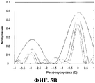
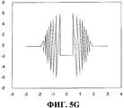
Фиг.5A-5H - диаграммы результатов, связанных со смещением начальной фазы для перераспределения энергии для 3-миллиметрового имплантата ВГХ между ближним, средним и дальним зрением в вариантах осуществления, соответствующих настоящему изобретению; и5A-5H are diagrams of results associated with an initial phase displacement for energy redistribution for a 3 mm VHC implant between near, middle and far vision in the embodiments of the present invention; and
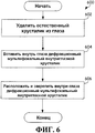
Фиг.6 - блок-схема последовательности операций способа коррекции ухудшения зрения, такого как афакия глаза.6 is a flowchart of a method for correcting visual impairment, such as aphakia of the eye.
Подробное описание изобретенияDETAILED DESCRIPTION OF THE INVENTION
Предпочтительные варианты осуществления настоящего изобретения представлены на чертежах, где схожие ссылочные позиции используются для схожих и соответствующих элементов.Preferred embodiments of the present invention are presented in the drawings, where like reference numerals are used for like and corresponding elements.
Предложена улучшенная дифракционная мультифокальная конструкция для глазного имплантата. Этот глазной имплантат содержит дифракционный мультифокальный внутриглазной хрусталик (имплантат ВГХ) и множество хэптиков (гаптических элементов). Дифракционный мультифокальный имплантат ВГХ пропускает световую энергию для дальнего, среднего и ближнего зрения. Хэптики механически соединены с дифракционным мультифокальным имплантатом ВГХ, чтобы расположить и закрепить дифракционный мультифокальный имплантат ВГХ внутри глаза. Дифракционный мультифокальный имплантат ВГХ может содержать как дифракционную область, так и рефракционную область, причем дифракционный мультифокальный имплантат ВГХ выполнен с возможностью сдвига фаз световой энергии, так что внутри дифракционной области и рефракционной области возникает конструктивная интерференция.An improved diffractive multifocal design for an ophthalmic implant is proposed. This ophthalmic implant contains a diffractive multifocal intraocular lens (HHV implant) and many haptics (haptic elements). The VHC diffractive multifocal implant transmits light energy for far, medium and near vision. Haptics are mechanically coupled to a HFD multifocal implant to position and fix the HFH diffractive multifocal implant inside the eye. The diffraction multifocal implant of the IHC can contain both a diffraction region and a refraction region, wherein the diffraction multifocal implant of the IHC is capable of phase shift of the light energy, so that constructive interference occurs within the diffraction region and the refractive region.
Зрение, безусловно, является одним из наших самых ценных чувств. Без зрения каждодневные задачи, такие как вождение автомобиля и чтение книг, были бы невозможны. Наши глаза являются сложными механизмами, дающими ясную картину мира вокруг нас, сообщают простейшие из цветов, форм и текстур. На фиг.1 представлена анатомия глаза, в которой может быть размещена улучшенная дифракционная мультифокальная конструкция глазного имплантата, представленная настоящим изобретением. Глаз 100 содержит роговицу 102, радужную оболочку 104, зрачок 106, хрусталик 108, капсулу хрусталика 110, пояски, ресничное тело, склеру 112, стекловидный гель 114, сетчатку 116, макулу и зрительный нерв 120. Роговица 102 является прозрачной, куполообразной структурой на поверхности глаза, действующей как окно, пропускающее свет в глаз. Радужная оболочка 104 является окрашенной частью глаза, называемой ирисом, и является мышцей, окружающей зрачок, который расслабляется и сжимается, чтобы управлять количеством света, поступающим в глаз. Зрачок 106 является круглым центральным отверстием ириса. Хрусталик 108 является структурой внутри глаза, которая помогает фокусировать свет на сетчатке. Капсула 110 хрусталика является эластичным мешком, заключающим в себе хрусталик, помогая управлять формой хрусталика, когда глаз фокусируется на объектах, расположенных на различных расстояниях. Пояски являются тонкими связками, которые прикрепляют капсулу хрусталика к внутренней части глаза, удерживая хрусталик на месте. Ресничное тело является мышечной областью, прикрепленной к хрусталику, которая сжимается и расслабляется, чтобы управлять размером хрусталика для фокусировки. Склера 112 является жестким, наиболее удаленным слоем глаза, который поддерживает форму глаза. Стекловидный гель 114 является большой, заполненной гелем секцией, которая располагается в направлении задней части глазного яблока и которая помогает поддерживать кривизну глаза. Сетчатка 116 является светочувствительный слоем нервов в задней части глаза, который принимает свет и преобразует его в сигналы для передачи к мозгу. Макула является областью в задней части глаза, которая имеет функции для рассматривания мелких деталей. Зрительный нерв 118 соединяет и передает сигналы от глаза к мозгу.Sight, of course, is one of our most valuable feelings. Without vision, everyday tasks, such as driving a car and reading books, would be impossible. Our eyes are complex mechanisms that give a clear picture of the world around us, the simplest of colors, shapes and textures inform. Figure 1 presents the anatomy of the eye, in which can be placed the improved diffractive multifocal ocular implant design of the present invention. The eye 100 contains the cornea 102, the iris 104, the pupil 106, the lens 108, the lens capsule 110, the girdles, the ciliary body, the sclera 112, the vitreous gel 114, the retina 116, the macula and the optic nerve 120. The cornea 102 is a transparent, domed structure on the surface eye acting as a window transmitting light into the eye. Iris 104 is the colored part of the eye called the iris, and is the muscle surrounding the pupil that relaxes and contracts to control the amount of light entering the eye. The pupil 106 is the round central opening of the iris. The lens 108 is a structure within the eye that helps focus light on the retina. The lens capsule 110 is an elastic bag enclosing the lens, helping to control the shape of the lens when the eye focuses on objects located at different distances. The belts are thin ligaments that attach the lens capsule to the inside of the eye, holding the lens in place. The ciliary body is the muscle area attached to the lens that contracts and relaxes to control the size of the lens for focusing. Sclera 112 is the stiffest, most distant layer of the eye that maintains the shape of the eye. Vitreous gel 114 is a large gel-filled section that extends toward the back of the eyeball and helps maintain eye curvature. The retina 116 is a photosensitive layer of nerves in the back of the eye that receives light and converts it into signals for transmission to the brain. The macula is an area in the back of the eye that has functions for viewing small details. The optic nerve 118 connects and transmits signals from the eye to the brain.
На фиг.2 представлен дифракционный имплантат ВГХ, соответствующий вариантам осуществления настоящего изобретения. Представленный дифракционный оптический имплантат ВГХ 200 является искусственным хрусталиком для имплантирования в глаз, чтобы восстановить зрение после удаления естественного хрусталика. Необходимость в имплантате ВГХ может быть следствием катаракты, болезни или несчастного случая. Хрусталик ВГХ может быть выпуклым с обеих сторон (двояковыпуклый) и изготовленным из мягкой пластмассы, которая может складываться перед введением, позволяя введение через разрез, меньший, чем оптический диаметр хрусталика. После хирургического введения в глаз хрусталик мягко разворачивается, чтобы восстановить зрение. Поддерживающие структуры (гаптические элементы, хэптики) 202 обеспечивают соответствующее расположение имплантата ВГХ внутри глаза.Figure 2 presents the diffraction implant VHC, corresponding to the variants of implementation of the present invention. The presented
Дифракционный оптический имплантат ВГХ 200 может помещаться в задней камере глаза, заменяя естественный хрусталик. Это положение позволяет дифракционному оптическому имплантату ВГХ 200 корректировать ухудшение зрения при афакии (отсутствии естественного хрусталика). У дифракционного оптического имплантата ВГХ 200 может быть двояковыпуклая оптика, которая формируется, используя процесс, называемый аподизированной дифракцией, чтобы обеспечить повышенную глубину резкости. Дифракционный оптический имплантат ВГХ 200 может использоваться для взрослых пациентов с пресбиопией и без нее, которые хотели бы обладать ближним, средним и дальним зрением с повышенной независимостью от очков после хирургии катаракты. Дифракционный оптический имплантат ВГХ 200 обеспечивает хорошее зрение при ближнем, среднем и дальнем зрении с повышенной независимостью от очков у больных, перенесших операцию катаракты. Дифракционный оптический имплантат ВГХ 200 обеспечивает качественное зрение для различных ситуаций с освещением. В условиях яркого освещения центральный дифракционный участок 204 передает световые волны одновременно к дальней, средней и ближней фокальным точкам, тогда как в условиях слабой освещенности окружающая рефракционная область 206 отправляет больше энергии к дальней точке фокуса.The
На фиг.3 представлен вид 300 в разрезе дифракционного мультифокального глазного хрусталика, имеющего множество кольцевых зон, который показан в соответствии с вариантами осуществления настоящего изобретения. Варианты осуществления предусматривают смещение по фазе между множеством кольцевых зон, чтобы улучшить дальнее зрение и сохранить хорошее среднее зрение. Величина фазового сдвига может быть тщательно оптимизирована, чтобы иметь конструктивную интерференцию между рефракционной областью центр-дальняя зона и дифракционной областью. Как следствие, улучшается дальнее зрение и расширяется среднее зрение. В частности, начальная фаза участка центр-дальняя зона регулируется, чтобы согласовать окружающую дифракционную структуру, чтобы конструктивная интерференция происходила в дальнем фокусе и в среднем фокусе. Смещение начальной фазы вверх перераспределяет энергию из ближнего фокуса в средний, а смещение вниз перераспределяет энергию от дальнего фокуса в средний. Хороший баланс достигается в одном варианте осуществления, смещая начальную фазу на 1/16 длины волны. Эта конструкция поддерживает хорошую дальнюю, среднюю и ближнюю фокусировку. Дополнительная оптимизация может привести к другим модифицированным конструкциям.FIG. 3 is a
Процесс определения этих кольцевых зон описывается в патенте US5699142 (Lee и др.), все содержание которого введено сюда посредством ссылки. Граница каждой зоны относительно оптической оси вычисляется. Ступени 302 располагаются на границах радиальной зоны различными индивидуальными эшелеттами. Прогрессирующе снижение высоты ступени выбранной группы индивидуальных эшелеттов 304 на заданную величину может уменьшить нежелательные эффекты блеска, воспринимаемого как ореол или кольца вокруг удаленного дискретного источника света. Выбранная группа индивидуальных эшелеттов, которые должны снижаться по высоте ступени, полностью содержится в том, что называют зоной аподизации.The process for determining these annular zones is described in US Pat. No. 5,699,142 (Lee et al.), The entire contents of which are incorporated herein by reference. The boundary of each zone relative to the optical axis is calculated.
Заметим, что высота ступени эшелеттов 304, окружающих оптическую ось (ОА), остается постоянной для несколько эшелеттов 304 до того, как размер ступени начнет уменьшаться. Затем, по мере того, как расстояние от каждого индивидуального эшелетта до оптической оси ОА увеличивается, высота ступени каждого эшелетта 304 приближается к нулю. В других вариантах осуществления высота эшелеттов 304, окружающих оптическую ось ОА, начинает уменьшаться с увеличением расстояния эшелетта 304 от оптической оси ОА. Эти эшеллеты могут быть дополнительно радиально сегментированы, как показано на фиг.4.Note that the step height of the
На фиг.4 вид сверху радиально сегментированного дифракционного мультифокального глазного хрусталика, характеризующегося множеством кольцевых зон, представлен в соответствии с вариантами осуществления настоящего изобретения, причем радиально сегментированный дифракционный мультифокальный глазной хрусталик 400 содержит хэптики 402, которые дополнительно содержат угловое соединение 416, изгиб 418 и дистальную часть 420, имеющую расширенный участок 422; оптику 410, которая содержит центральный радиально аподизированный дифракционный участок 404, имеющий радиально сегментированные зоны 424 и окружающую рефракционную область 406. В одном варианте осуществления толщина конструкции изгиба 418 и дистального участка 420 хэптика 402 являются одинаковой и, предпочтительно, приблизительно в пределах от 0,30 мм до 0,60 мм, приблизительно от 0,40 мм, и более предпочтительно 0,50 мм, и приблизительно 0,43 является наиболее предпочтительной толщиной. Угловые соединения 416, однако, имеют толщину, которая уменьшается в направлении передней стороны 212 оптики. Угловые соединения 416 предпочтительно имеют толщину приблизительно в пределах от 0,15 мм до 0,60 мм, более предпочтительно от 0,25 мм до 0,35 мм, и наиболее предпочтительно приблизительно 0,30 мм. Этот участок с пониженной толщиной обычно расширяется от края 208 оптики. Относительно тонкое поперечное сечение угловых соединений 416 и края 308 обеспечивает более тонкий профиль, когда имплантат ВГХ 400 вставляется через хирургический разрез. Уменьшенная толщина угловых соединений 416 также облегчает циркуляцию текучей среды (например, вязкоупругой) между задней стороной 214 и передней стороной 212 имплантата ВГХ. Альтернативно, угловые соединения 416 или оптика 410 могут обеспечиваться другим средством (таким как отверстия, канавки, вырезки, микроячейки или выпуклости (не показаны), чтобы облегчить поток текучей среды между задней стороной 214 и передней стороной 212 имплантата ВГХ. Относительно большая длина и радиус дистального участка 420 обеспечивает больший контакт капсульного мешка для лучшей фиксации, когда имплантат ВГХ 400 имплантируется в глаз. Изгиб 418 создает шарнир, позволяющий хэптику 402 изгибаться, минимизируя продольный изгиб и поднятие свода оптики 410. Расширенный участок 422 увеличивает жесткость хэптика 402 сразу после изгиба 418, увеличивая, таким образом, прочность хэптика 402 в точке критического напряжения.Figure 4 is a top view of a radially segmented diffractive multifocal ocular lens, characterized by a plurality of annular zones, shown in accordance with embodiments of the present invention, wherein the radially segmented diffractive multifocal
Варианты осуществления настоящего изобретения обеспечивают улучшенную аподизированную мультифокальную конструкцию глазного имплантата, такого как внутриглазной хрусталик (ВГХ), который использует профиль для обеспечения улучшенного дальнего зрения для суженных зрачков в таких условиях как дневное освещение, и улучшенного ближнего зрения для увеличенных зрачков по сравнению с ранее доступными аподизированными дифракционными мультифокальными хрусталиками. Некоторые пациенты нуждаются в более ясном зрении в дальней зоне при суженном зрачке, то есть, при условиях дневного освещения. Аналогично, некоторые пациенты требуют лучшего зрения при увеличенном зрачке, то есть, при неярком свете. Например, некоторые пациенты испытывают затруднения при чтении меню в ресторанах с тусклым светом, где размер зрачка может составлять 4 мм или больше. Варианты осуществления настоящего изобретения используют распределение энергии мультифокальной конструкции и оптимизируются для достижения более высокой энергии для дальнего зрения при размере зрачка 2,75 мм или меньше. Одновременно достигается более высокая энергия для ближнего зрения по сравнению с ранее доступными глазными имплантатами со зрачком 3,5 мм или больше.Embodiments of the present invention provide an improved apodized multifocal ocular implant design, such as an intraocular lens (IHC), which uses a profile to provide improved far vision for narrowed pupils in conditions such as daylight, and improved near vision for enlarged pupils compared to previously available apodized diffractive multifocal lenses. Some patients require clearer vision in the far zone with a narrowed pupil, that is, under daylight conditions. Similarly, some patients require better vision with an enlarged pupil, that is, in dim light. For example, some patients have difficulty reading menus in dim-light restaurants where the pupil size can be 4 mm or more. Embodiments of the present invention utilize the energy distribution of a multifocal structure and are optimized to achieve higher energy for long-range vision with a pupil size of 2.75 mm or less. At the same time, higher energy for near vision is achieved compared to previously available eye implants with a pupil of 3.5 mm or more.
Варианты осуществления также обеспечивают другие характеристики глазного имплантата, содержащие тонкий край для оказания помощи при меньшем разрезе во время хирургии для имплантации; приблизительно 5-10% или больше улучшения значения MTF при размере зрачка 2 и 2,5мм или меньше по сравнению с ранее доступными аподизированными мультифокальными конструкциями; и приблизительно 15% или более улучшения значения MTF при размере зрачка 3,5 мм или больше для ближнего зрения, по сравнению с ранее доступными аподизированными мультифокальными конструкциями. Улучшение 5-10% или больше для суженных зрачков позволяет иметь лучшее дальнее зрение в условиях дневного освещения. Аналогично, улучшение 15% для расширенных зрачков позволяет иметь улучшенное ближнее зрение в сумерках или при тусклом свете. Варианты осуществления настоящего изобретения свидетельствуют, что можно уменьшать энергию в ближней зоне и использовать большую область хрусталика, которая направляет свет в ближнюю зону, в то же время обеспечивая хорошие визуальные характеристики. Варианты осуществления могут оптимизировать область конструктивных улучшений, позволяющих получить лучшее зрение при всех условиях освещения, таких как дневные и сумеречные условия для конкретных зрачков. В рамках некоторых вариантов осуществления, соответствующих настоящему изобретению, визуальные нарушения не будут увеличиваться ночью.Embodiments also provide other ophthalmic implant characteristics, comprising a thin edge to assist with a smaller incision during implant surgery; approximately 5-10% or more improvement in MTF value at a pupil size of 2 and 2.5 mm or less compared to previously available apodized multifocal designs; and about 15% or more improvement in MTF at a pupil size of 3.5 mm or more for near vision compared to previously available apodized multifocal designs. An improvement of 5-10% or more for narrowed pupils allows you to have better long-range vision in daylight conditions. Similarly, a 15% improvement for dilated pupils allows for improved near vision at dusk or in dim light. Embodiments of the present invention indicate that it is possible to reduce energy in the near zone and use a large area of the lens that directs light into the near zone, while at the same time providing good visual characteristics. Embodiments may optimize the scope of design improvements to provide better vision under all lighting conditions, such as daytime and twilight conditions for particular pupils. In some embodiments of the present invention, visual disturbances will not increase at night.
На фиг.5A-5H представлены диаграммы, показывающие результаты, связанные со смещением начальной фазы для перераспределения энергии между ближним, средним и дальним зрением для 3-хмиллиметрового имплантата ВГХ в вариантах осуществления, соответствующих настоящему раскрытию. Варианты осуществления обеспечивают фазовое смещение в рамках комбинации дифракционной оптики для улучшения дальнего зрения и поддержания хорошего среднего зрения. Величина сдвига фаз может тщательно оптимизироваться, чтобы иметь конструктивную интерференцию между рефракционной областью центр-дальняя зона и дифракционной областью. Как следствие, улучшается дальнее зрение и среднее зрение расширяется. Конкретно, начальная фаза области центр-дальняя зона регулируется, чтобы согласовываться с окружающей дифракционной структурой, так чтобы конструктивная интерференция происходила в дальнем фокусе и в среднем фокусе. Смещение начальной фазы вверх перераспределяет энергию из ближнего фокуса в средний, а смещение вниз перераспределяет энергию из дальнего фокуса в средний. Хороший баланс достигается в одном из вариантов конструкции при смещении начальной фазы на 1/16 длины волны. Эта конструкция поддерживает хороший дальний, средний и ближний фокусы. На фиг.5A и 5B область DD дальний-центр смещается вверх на 1/8 длины волны. На фиг.5C и 5D область DD дальний-центр смещается вниз на 1/8 длины волны. На фиг.5E и 5F 5H область DD дальний-центр не смещается. На фиг.5G и 5H область DD дальний-центр смещается вниз на 1/16 длины волны. Дополнительная оптимизация может привести в результате к другими модифицированными конструкциям.FIGS. 5A-5H are diagrams showing the results associated with an initial phase shift for energy redistribution between near, middle and far vision for a 3 mm VHC implant in the embodiments of the present disclosure. Embodiments provide phase shift as part of a combination of diffraction optics to improve long-range vision and maintain good average vision. The magnitude of the phase shift can be carefully optimized to have constructive interference between the refractive region of the center-far zone and the diffraction region. As a result, far vision improves and secondary vision expands. Specifically, the initial phase of the center-far region is adjusted to match the surrounding diffraction structure so that constructive interference occurs at the far focus and mid focus. An upward shift of the initial phase redistributes the energy from the near focus to the middle, and a downward shift redistributes the energy from the far focus to the middle. Good balance is achieved in one of the design options when the initial phase is shifted by 1/16 of the wavelength. This design supports good far, middle and near focus. 5A and 5B, the far-center region DD shifts upward by 1/8 of the wavelength. In FIGS. 5C and 5D, the far-center region DD shifts downward by 1/8 of the wavelength. 5E and 5F 5H, the far-center region DD is not shifted. In FIGS. 5G and 5H, the far-center region DD shifts downward by 1/16 of the wavelength. Additional optimization may result in other modified designs.
Как показано на чертежах, варианты осуществления, изложенные в настоящем изобретении, могут обеспечивать более ясное дальнее зрение при суженном зрачке, то есть, в условиях дневного освещения, и лучшее зрение при расширенном зрачке, то есть, в сумерках.As shown in the drawings, the embodiments set forth in the present invention can provide clearer distant vision with a narrowed pupil, that is, in daylight conditions, and better vision with an enlarged pupil, that is, at dusk.
На фиг.6 представлена блок-схема последовательности операций способа коррекции ухудшенного зрения, такого как афакия глаза. Операции 600 начинаются с удаления естественного хрусталика из глаза на этапе 602. Аподизированный дифракционный мультифокальный имплантат ВГХ может затем быть вставлен внутрь глаза. Линзы дифракционного мультифокального ВГХ могут быть выпуклыми с обеих сторон (двояковыпуклыми) и изготовленными из мягкой пластмассы, которая может сгибаться перед введением. Такое сгибание позволяет вставлять имплантат ВГХ через разрез меньшего размера, причем разрез меньше, чем оптический диаметр дифракционного мультифокального имплантата ВГХ. После хирургического введения в глаз на этапе 604 ВГХ может мягко развернуться, чтобы восстановить зрение. На этапе 606 ВГХ размещается и закрепляется внутри глаза. Это может быть сделано с использованием поддерживающих структур (хэптиков), чтобы обеспечить надлежащее расположение ВГХ внутри глаза. Варианты осуществления, соответствующие настоящему изобретению, могут помещать или устанавливать имплантат ВГХ в задней камере глаза, чтобы заменить естественный хрусталик, как показано на фиг.1. Это положение позволяет корректировать нарушения зрения, такое как отсутствие естественного хрусталика из-за болезни или несчастного случая. Сам хрусталик может быть дифракционным мультифокальным имплантатом ВГХ, как обсуждалось раньше. Это позволяет пациентам с пресбиопией и без нее, которые желают иметь зрение в ближней зоне, средней зоне и дальней зоне, быть независимыми от очков после хирургии, такой как хирургия катаракты.6 is a flowchart of a method for correcting impaired vision, such as aphakia of the eye.
Обобщая вышесказанное, варианты осуществления, соответствующие настоящему изобретению, обеспечивают улучшенную дифракционную мультифокальную конструкцию для глазного имплантата. Этот глазной имплантат содержит дифракционный мультифокальный внутриглазной хрусталик (имплантат ВГХ) и много хэптиков. Дифракционный мультифокальный ВГХ пропускает световую энергию для дальнего, среднего и ближнего зрения. Хэптики механически соединяются с дифракционным мультифокальным ВГХ, чтобы расположить и закрепить дифракционный мультифокальный ВГХ внутри глаза. Дифракционный мультифокальный имплантат ВГХ может содержать как дифракционную область, так и рефракционную область. Дифракционная область может быть центральной областью или оптической зоной хрусталика, который содержит концентрические ступени с постепенно изменяющейся высотой ступени, чтобы распределять энергию, основываясь на условиях освещения и работы, создавая полный диапазон качественного зрения, то есть, от ближнего до дальнего зрения. Это позволяет корректировать условия, в которых естественный хрусталик глаза должен быть заменен.Summarizing the above, the embodiments of the present invention provide an improved diffractive multifocal design for an ophthalmic implant. This ophthalmic implant contains a diffractive multifocal intraocular lens (HHV implant) and many haptics. Diffractive multifocal VHC transmits light energy for far, medium and near vision. Haptics mechanically combine with diffractive multifocal IHC to position and fix the diffractive multifocal IHC within the eye. The GFH multifocal diffraction implant may contain both a diffraction region and a refraction region. The diffraction region can be a central region or an optical zone of the lens that contains concentric steps with a gradually changing step height to distribute energy based on lighting and work conditions, creating a full range of quality vision, i.e., from near to far vision. This allows you to adjust the conditions in which the natural lens of the eye needs to be replaced.
Другие варианты осуществления настоящего изобретения обеспечивают способ коррекции ухудшения зрения при афакии. В одном варианте осуществления при этом удаляют из глаза естественный хрусталик, когда хрусталик подвержен заболеванию или пострадал от несчастного случая. Затем дифракционный мультифокальный имплантат ВГХ может быть вставлен внутрь глаза и далее размещен и закреплен с помощью множества хэптиков. Дифракционная область дифракционного мультифокального имплантата ВГХ может одновременно пропускать световую энергию к дальнему, среднему и ближнему фокусам в условия большой яркости, тогда как внешняя рефракционная область может пропускать световую энергию для дальнего зрения в условиях неяркого света. Еще один вариант осуществления, соответствующий настоящему раскрытию, обеспечивает способ коррекции ухудшенного зрения. Этот способ содержит пропускание световой энергии к сетчатке, где может отображаться световая энергия. Эта световая энергия пропускается дифракционным мультифокальным имплантатом ВГХ, обычно располагающимся внутри глаза, и используется для замены естественного хрусталика. Дифракционный мультифокальный имплантат ВГХ пропускает световую энергию в условиях дальнего, среднего и ближнего зрения. Дифракционный мультифокальный имплантат ВГХ может иметь центральную дифракционную область и внешнюю рефракционную область.Other embodiments of the present invention provide a method for correcting visual impairment in aphakia. In one embodiment, the natural lens is removed from the eye when the lens is susceptible to disease or has suffered an accident. Then, the VHC diffractive multifocal implant can be inserted inside the eye and then placed and secured with the help of many haptics. The diffraction region of the VHC multifocal diffraction implant can simultaneously transmit light energy to the far, middle and near foci in high brightness conditions, while the external refractive region can transmit light energy for far vision in dim light conditions. Another embodiment corresponding to the present disclosure provides a method for correcting impaired vision. This method comprises transmitting light energy to the retina, where light energy can be displayed. This light energy is transmitted through a diffraction multifocal VHC implant, usually located inside the eye, and is used to replace the natural lens. The diffraction multifocal implant VHC transmits light energy in the conditions of far, medium and near vision. The diffraction multifocal VHC implant may have a central diffraction region and an external refraction region.
Варианты осуществления, соответствующие настоящему изобретению, позволяют пациентам, страдающим ухудшением зрения, иметь ясное зрение при дальнем зрении, т.е. суженном размере зрачка, то есть, в условиях дневного освещения, и иметь улучшенное зрение при расширенном зрачке, то есть, в условиях сумерек.Embodiments of the present invention allow patients suffering from impaired vision to have clear vision with distant vision, i.e. narrowed pupil size, that is, in daylight, and have improved vision with an enlarged pupil, that is, in twilight conditions.
Как должен понимать средний специалист в данной области техники, термин "по существу" или "приблизительно", как он может использоваться здесь, обеспечивает приемлемый для промышленности допуск для соответствующей позиции. Как должен дополнительно понимать средний специалист в данной области техники, термин "с возможностью соединения", как он может использоваться здесь, содержит прямое соединение и косвенное соединение через другой узел, элемент, схему или модуль. Как должен также понимать средний специалист в данной области техники, подразумеваемое соединение (то есть, когда подразумевается, что один элемент связывается с другим элементом) содержит прямое соединение и косвенное соединение между двумя элементами тем же самым способом, что и "с возможностью соединения". Как дополнительно должен понимать средний специалист в данной области техники, термин "сравнение с положительным результатом", как он может использоваться здесь, указывает, что сравнение между двумя или больше элементами, объектами, сигналами и т.д., обеспечивает желаемое соотношение.As one of ordinary skill in the art would understand, the term “substantially” or “approximately”, as used herein, provides industry tolerance for the relevant position. As one of ordinary skill in the art should further understand, the term “connectable,” as used herein, includes a direct connection and an indirect connection through another node, element, circuit, or module. As should also be understood by one of ordinary skill in the art, an implied connection (that is, when it is understood that one element binds to another element) contains a direct connection and an indirect connection between two elements in the same manner as “connectivity”. As an additional person skilled in the art should understand, the term "comparison with a positive result", as it can be used here, indicates that the comparison between two or more elements, objects, signals, etc., provides the desired ratio.
Хотя настоящее изобретение описывается подробно, следует понимать, что в нем могут быть сделаны различные изменения, замены и модификации, не отступая от сущности и объема изобретения, как описано в приложенной формуле изобретения.Although the present invention is described in detail, it should be understood that various changes, substitutions and modifications can be made therein without departing from the spirit and scope of the invention, as described in the attached claims.
Claims (7)
дифракционный мультифокальный внутриглазной хрусталик (имплантат ВГХ), выполненный с возможностью обеспечения дальнего, ближнего и среднего фокусов, причем дифракционный мультифокальный имплантат ВГХ имеет тонкую кромку, выполненную с возможностью обеспечения меньшего разреза,
причем дифракционный мультифокальный имплантат ВГХ содержит бифокальную дифракционную область, обеспечивающую только дальний и ближний фокусы, рефракционную область центр-дальняя зона и внешнюю рефракционную область, причем фаза внешней рефракционной области совпадает с фазой бифокальной дифракционной области, и фаза рефракционной области центр-дальняя зона сдвинута по фазе от бифокальной дифракционной области в пределах от 1/8 до 1/16 длины волны, чтобы сдвигать световую энергию по фазе так, чтобы конструктивная интерференция между рефракционной областью центр-дальняя зона и бифокальной дифракционной областью происходила и в дальнем фокусе, и в среднем фокусе; и
множество гаптических элементов, связанных с дифракционным мультифокальным имплантатом ВГХ и выполненных с возможностью расположения дифракционного мультифокального имплантата ВГХ внутри глаза.1. An eye implant containing:
a diffractive multifocal intraocular lens (VHC implant), configured to provide far, near and middle foci, moreover, a diffractive multifocal implant VHC has a thin edge configured to provide a smaller incision,
moreover, the GVH diffraction multifocal implant contains a bifocal diffraction region providing only the far and near foci, a center-far zone refraction region and an external refraction region, wherein the phase of the external refraction region coincides with the phase of the bifocal diffraction region, and the phase of the refraction region center-far zone is shifted phase from the bifocal diffraction region in the range of 1/8 to 1/16 of the wavelength in order to shift the light energy in phase so that the constructive interference between p fractional area of the center, far zone and a bifocal diffractive region occurs in the far focus, and the focus on the average; and
many haptic elements associated with the diffraction multifocal implant of the IHC and configured to position the diffraction multifocal implant of the IHC within the eye.
бифокальная дифракционная область выполнена с возможностью пропускания световой энергии одновременно к дальнему, среднему и ближнему фокусам в условиях оптической яркости; и
рефракционная область выполнена с возможностью пропускания световой энергии для дальнего зрения в условиях неяркого света.2. An eye implant according to claim 1, in which:
the bifocal diffraction region is configured to transmit light energy simultaneously to the far, middle and near foci under conditions of optical brightness; and
the refractive region is configured to transmit light energy for distant vision in dim light conditions.
множество концентрических ступеней с переменной высотой ступени, которые распределяют энергию, основываясь на условиях освещения и активности для формирования полного диапазона зрения от ближнего до дальнего фокусов.4. An ocular implant according to claim 1, in which the diffraction region contains:
many concentric steps with variable height steps that distribute energy based on lighting and activity conditions to form a full range of vision from near to far foci.
удаляют естественный хрусталик глаза;
вставляют дифракционный мультифокальный внутриглазной хрусталик (имплантат ВГХ), причем дифракционный мультифокальный имплантат ВГХ выполнен с возможностью обеспечения ближнего фокуса, среднего фокуса и дальнего фокуса, при этом дифракционный мультифокальный имплантат ВГХ содержит:
рефракционную область центр-дальняя зона;
центральную бифокальную дифракционную область,
обеспечивающую только дальний и ближний фокусы; и
внешнюю рефракционную область, причем фаза внешней рефракционной области совпадает с фазой центральной бифокальной дифракционной области, чтобы сдвигать световую энергию по фазе, а фаза рефракционной области центр-дальняя зона сдвинута по фазе от бифокальной дифракционной области в пределах от 1/8 до 1/16 длины волны так, что происходит конструктивная интерференция между рефракционной областью центр-дальняя зона и бифокальной дифракционной областью с центральной бифокальной дифракционной областью и рефракционной областью центр-дальняя зона в среднем и дальнем фокусах;
располагают и закрепляют дифракционный мультифокальный имплантат ВГХ внутри глаза с помощью множества гаптических элементов, соединенных с дифракционным мультифокальным имплантатом ВГХ.5. A method for correcting visual impairment in aphakia, comprising the steps of:
remove the natural lens of the eye;
a diffractive multifocal intraocular lens (HH implant) is inserted, wherein the HF diffractive multifocal implant is configured to provide near focus, medium focus and far focus, while the HH diffractive multifocal implant contains:
refractive region center-far zone;
central bifocal diffraction region,
providing only far and near tricks; and
external refractive region, and the phase of the external refractive region coincides with the phase of the central bifocal diffraction region in order to shift the light energy in phase, and the phase of the refractive region center-far zone is phase shifted from the bifocal diffraction region in the range from 1/8 to 1/16 of the length waves so that constructive interference occurs between the center-far zone refractive region and the bifocal diffraction region with the central bifocal diffraction region and the center-far refractive region I zone in the middle and far focus;
position and fix the diffraction multifocal implant of the IHC inside the eye using a variety of haptic elements connected to the diffraction multifocal implant of the IHC.
множество концентрических ступеней с переменной высотой ступени, которые распределяют энергию, исходя из условий освещения и активности, для формирования полного диапазона зрения от ближнего до дальнего фокусов. 7. The method according to p. 5, in which the Central diffraction region contains:
a lot of concentric steps with a variable height of the stage, which distribute energy, based on lighting conditions and activity, to form a full range of vision from near to far foci.
Applications Claiming Priority (3)
| Application Number | Priority Date | Filing Date | Title |
|---|---|---|---|
| US25493809P | 2009-10-26 | 2009-10-26 | |
| US61/254,938 | 2009-10-26 | ||
| PCT/US2010/053784 WO2011053532A1 (en) | 2009-10-26 | 2010-10-22 | Phase-shifted center-distance diffractive design for ocular implant |
Publications (2)
| Publication Number | Publication Date |
|---|---|
| RU2012121889A RU2012121889A (en) | 2013-12-10 |
| RU2552699C2 true RU2552699C2 (en) | 2015-06-10 |
Family
ID=43899084
Family Applications (1)
| Application Number | Title | Priority Date | Filing Date |
|---|---|---|---|
| RU2012121889/14A RU2552699C2 (en) | 2009-10-26 | 2010-10-22 | Diffraction structure with phase shift of centre and far zone for ocular implant |
Country Status (15)
| Country | Link |
|---|---|
| US (1) | US8652205B2 (en) |
| EP (1) | EP2493421B1 (en) |
| JP (1) | JP5763656B2 (en) |
| KR (1) | KR101798031B1 (en) |
| CN (1) | CN102762169B (en) |
| AR (1) | AR078767A1 (en) |
| AU (1) | AU2010313599B2 (en) |
| CA (1) | CA2776738C (en) |
| ES (1) | ES2564932T3 (en) |
| IL (1) | IL219106A0 (en) |
| MX (1) | MX2012004531A (en) |
| NZ (1) | NZ599397A (en) |
| RU (1) | RU2552699C2 (en) |
| TW (1) | TWI514994B (en) |
| WO (1) | WO2011053532A1 (en) |
Families Citing this family (22)
| Publication number | Priority date | Publication date | Assignee | Title |
|---|---|---|---|---|
| US9335563B2 (en) | 2012-08-31 | 2016-05-10 | Amo Groningen B.V. | Multi-ring lens, systems and methods for extended depth of focus |
| TWI588560B (en) | 2012-04-05 | 2017-06-21 | 布萊恩荷登視覺協會 | Lenses, devices, methods and systems for refractive error |
| US9201250B2 (en) | 2012-10-17 | 2015-12-01 | Brien Holden Vision Institute | Lenses, devices, methods and systems for refractive error |
| CN104768499B (en) | 2012-10-17 | 2017-06-23 | 华柏恩视觉研究中心 | For ametropic eyeglass, device, method and system |
| EP2908777B1 (en) | 2012-12-18 | 2017-08-02 | Novartis AG | System for providing an intraocular lens having an improved depth of field |
| BR112016024234B1 (en) * | 2014-04-18 | 2022-05-10 | Investmed Kft | Secondary intraocular lens (Ilium) |
| KR101840612B1 (en) * | 2014-07-25 | 2018-03-20 | 무사시노 렌즈 리서치, 아이엔씨. | Phakic intraocular lens |
| KR20190025765A (en) * | 2014-08-07 | 2019-03-11 | 샤크렛 테크놀러지스, 아이엔씨. | Patterns for flow control and bioadhesion control |
| EP3130314A1 (en) * | 2015-08-12 | 2017-02-15 | PhysIOL SA | Trifocal intraocular lens with extended range of vision and correction of longitudinal chromatic aberration |
| AU2017218681B2 (en) | 2016-02-09 | 2021-09-23 | Amo Groningen B.V. | Progressive power intraocular lens, and methods of use and manufacture |
| US10426599B2 (en) * | 2016-11-29 | 2019-10-01 | Novartis Ag | Multifocal lens having reduced chromatic aberrations |
| EP3595584A1 (en) | 2017-03-17 | 2020-01-22 | AMO Groningen B.V. | Diffractive intraocular lenses for extended range of vision |
| US10433951B2 (en) | 2017-05-22 | 2019-10-08 | Rxsight, Inc. | Depth of focus and visual acuity using colorized apodization of intra-ocular lenses |
| US11523897B2 (en) | 2017-06-23 | 2022-12-13 | Amo Groningen B.V. | Intraocular lenses for presbyopia treatment |
| CA3067116A1 (en) | 2017-06-28 | 2019-01-03 | Amo Groningen B.V. | Diffractive lenses and related intraocular lenses for presbyopia treatment |
| AU2018292030B2 (en) | 2017-06-28 | 2024-02-08 | Amo Groningen B.V. | Extended range and related intraocular lenses for presbyopia treatment |
| US11327210B2 (en) | 2017-06-30 | 2022-05-10 | Amo Groningen B.V. | Non-repeating echelettes and related intraocular lenses for presbyopia treatment |
| CN108652789B (en) * | 2017-07-20 | 2020-04-21 | 东莞东阳光医疗智能器件研发有限公司 | Full-range diffractive intraocular lens with enhanced near vision |
| JP2021520875A (en) * | 2018-04-12 | 2021-08-26 | アルコン インコーポレイティド | Full depth of focus intraocular lens |
| CN114901210A (en) * | 2019-12-17 | 2022-08-12 | 爱尔康公司 | Intraocular lens with increased optical diameter |
| AU2020416055A1 (en) | 2019-12-30 | 2022-08-25 | Amo Groningen B.V. | Lenses having diffractive profiles with irregular width for vision treatment |
| DE102022209520A1 (en) | 2022-09-12 | 2024-03-14 | Carl Zeiss Meditec Ag | OPHTHALMIC LENS AND METHOD FOR DESIGNING AND MANUFACTURING SAME |
Citations (5)
| Publication number | Priority date | Publication date | Assignee | Title |
|---|---|---|---|---|
| RU2241421C1 (en) * | 2003-05-16 | 2004-12-10 | Липатов Дмитрий Валентинович | Method for correcting intraocular aphakia in the cases of marked lens ligament-capsule apparatus inconsistency |
| US20060116764A1 (en) * | 2004-12-01 | 2006-06-01 | Simpson Michael J | Apodized aspheric diffractive lenses |
| US7156516B2 (en) * | 2004-08-20 | 2007-01-02 | Apollo Optical Systems Llc | Diffractive lenses for vision correction |
| US20090187242A1 (en) * | 2007-08-27 | 2009-07-23 | Advanced Medical Optics, Inc. | Intraocular lens having extended depth of focus |
| US20090234448A1 (en) * | 2007-08-27 | 2009-09-17 | Advanced Medical Optics, Inc. | Intraocular lens having extended depth of focus |
Family Cites Families (69)
| Publication number | Priority date | Publication date | Assignee | Title |
|---|---|---|---|---|
| US514483A (en) * | 1894-02-13 | Marcelltjs h | ||
| US4210391A (en) | 1977-09-14 | 1980-07-01 | Cohen Allen L | Multifocal zone plate |
| US4162122A (en) | 1977-09-14 | 1979-07-24 | Cohen Allen L | Zonal bifocal contact lens |
| US4340283A (en) | 1978-12-18 | 1982-07-20 | Cohen Allen L | Phase shift multifocal zone plate |
| US4338005A (en) | 1978-12-18 | 1982-07-06 | Cohen Allen L | Multifocal phase place |
| JPS584632B2 (en) * | 1978-12-30 | 1983-01-27 | アルプス電気株式会社 | printing device |
| DE3265356D1 (en) | 1981-04-29 | 1985-09-19 | Pilkington Perkin Elmer Ltd | Artificial eye lenses |
| DE3374446D1 (en) | 1982-09-29 | 1987-12-17 | Pilkington Brothers Plc | Improvements in or relating to ophthalmic lenses |
| DE3377535D1 (en) | 1982-10-27 | 1988-09-01 | Pilkington Plc | Bifocal contact lens comprising a plurality of concentric zones |
| GB8404817D0 (en) | 1984-02-23 | 1984-03-28 | Pilkington Perkin Elmer Ltd | Ophthalmic lenses |
| US5017000A (en) | 1986-05-14 | 1991-05-21 | Cohen Allen L | Multifocals using phase shifting |
| US5121979A (en) | 1986-05-14 | 1992-06-16 | Cohen Allen L | Diffractive multifocal optical device |
| US5144483A (en) | 1986-05-14 | 1992-09-01 | Cohen Allen L | Diffractive multifocal optical device |
| US4881804A (en) | 1987-11-12 | 1989-11-21 | Cohen Allen L | Multifocal phase plate with a pure refractive portion |
| US4881805A (en) | 1987-11-12 | 1989-11-21 | Cohen Allen L | Progressive intensity phase bifocal |
| US5056908A (en) | 1987-11-12 | 1991-10-15 | Cohen Allen L | Optic zone phase channels |
| US5054905A (en) | 1987-11-12 | 1991-10-08 | Cohen Allen L | Progressive intensity phase bifocal |
| US4888012A (en) | 1988-01-14 | 1989-12-19 | Gerald Horn | Intraocular lens assemblies |
| US5076684A (en) | 1988-04-01 | 1991-12-31 | Minnesota Mining And Manufacturing Company | Multi-focal diffractive ophthalmic lenses |
| CA1316728C (en) | 1988-04-01 | 1993-04-27 | Michael J. Simpson | Multi-focal diffractive ophthalmic lenses |
| US5116111A (en) | 1988-04-01 | 1992-05-26 | Minnesota Mining And Manufacturing Company | Multi-focal diffractive ophthalmic lenses |
| DE3854966T2 (en) | 1988-07-20 | 1996-05-30 | Allen L Cohen | Multifocal, diffractive optical device |
| US4995714A (en) * | 1988-08-26 | 1991-02-26 | Cohen Allen L | Multifocal optical device with novel phase zone plate and method for making |
| US5185107A (en) | 1988-10-26 | 1993-02-09 | Iovision, Inc. | Fabrication of an intraocular lens |
| US5121980A (en) | 1989-04-19 | 1992-06-16 | Cohen Allen L | Small aperture multifocal |
| US5096285A (en) | 1990-05-14 | 1992-03-17 | Iolab Corporation | Multifocal multizone diffractive ophthalmic lenses |
| US5117306A (en) | 1990-07-17 | 1992-05-26 | Cohen Allen L | Diffraction bifocal with adjusted chromaticity |
| US5120120A (en) | 1990-07-27 | 1992-06-09 | Cohen Allen L | Multifocal optical device with spurious order suppression and method for manufacture of same |
| US5257132A (en) | 1990-09-25 | 1993-10-26 | The United States Of America As Represented By The United States Department Of Energy | Broadband diffractive lens or imaging element |
| US5217489A (en) | 1991-04-05 | 1993-06-08 | Alcon Surgical, Inc. | Bifocal intraocular lens |
| US5895422A (en) | 1993-06-17 | 1999-04-20 | Hauber; Frederick A. | Mixed optics intraocular achromatic lens |
| US5470932A (en) | 1993-10-18 | 1995-11-28 | Alcon Laboratories, Inc. | Polymerizable yellow dyes and their use in opthalmic lenses |
| US5699142A (en) | 1994-09-01 | 1997-12-16 | Alcon Laboratories, Inc. | Diffractive multifocal ophthalmic lens |
| US5650838A (en) | 1995-05-04 | 1997-07-22 | Johnson & Johnson Vision Products, Inc. | Programmable smooth junctions on lenses |
| WO1996039106A1 (en) | 1995-06-06 | 1996-12-12 | Scientific Optics, Inc. | Asymmetric bifocal intraocular lens |
| US5716403A (en) * | 1995-12-06 | 1998-02-10 | Alcon Laboratories, Inc. | Single piece foldable intraocular lens |
| US6786928B2 (en) * | 1997-08-20 | 2004-09-07 | Thinoptx, Inc. | Small incision lens |
| US6800091B2 (en) | 1997-08-20 | 2004-10-05 | Thinoptx, Inc. | Method of using a small incision lens |
| US6158862A (en) | 1997-12-04 | 2000-12-12 | Alcon Laboratories, Inc. | Method of reducing glare associated with multifocal ophthalmic lenses |
| US6197057B1 (en) * | 1998-10-27 | 2001-03-06 | Gholam A. Peyman | Lens conversion system for teledioptic or difractive configurations |
| US6536899B1 (en) * | 1999-07-14 | 2003-03-25 | Bifocon Optics Gmbh | Multifocal lens exhibiting diffractive and refractive powers |
| US6685315B1 (en) | 1999-09-03 | 2004-02-03 | De Carle John Trevor | Bifocal lenses |
| US6599317B1 (en) | 1999-09-17 | 2003-07-29 | Advanced Medical Optics, Inc. | Intraocular lens with a translational zone |
| US6596026B1 (en) | 2000-11-27 | 2003-07-22 | Visioncare Ophthalmic Technologies, Inc. | Telescopic intraocular lens |
| US6638305B2 (en) | 2001-05-15 | 2003-10-28 | Advanced Medical Optics, Inc. | Monofocal intraocular lens convertible to multifocal intraocular lens |
| US20030014107A1 (en) | 2001-06-28 | 2003-01-16 | Michael Reynard | Multifocal phakic intraocular lens |
| US6695881B2 (en) | 2002-04-29 | 2004-02-24 | Alcon, Inc. | Accommodative intraocular lens |
| US6923540B2 (en) | 2002-07-31 | 2005-08-02 | Novartis Ag | Toric multifocal contact lenses |
| US7896916B2 (en) | 2002-11-29 | 2011-03-01 | Amo Groningen B.V. | Multifocal ophthalmic lens |
| US7186266B2 (en) * | 2003-06-06 | 2007-03-06 | Teledioptic Lens System, Llc | Bifocal intraocular telescope for low vision correction |
| US6951391B2 (en) * | 2003-06-16 | 2005-10-04 | Apollo Optical Systems Llc | Bifocal multiorder diffractive lenses for vision correction |
| US7150760B2 (en) | 2004-03-22 | 2006-12-19 | Alcon, Inc. | Accommodative intraocular lens system |
| US20060066808A1 (en) | 2004-09-27 | 2006-03-30 | Blum Ronald D | Ophthalmic lenses incorporating a diffractive element |
| JP4926068B2 (en) | 2004-10-25 | 2012-05-09 | アボット・メディカル・オプティクス・インコーポレイテッド | Ophthalmic lens having a plurality of phase plates |
| US7188949B2 (en) | 2004-10-25 | 2007-03-13 | Advanced Medical Optics, Inc. | Ophthalmic lens with multiple phase plates |
| US20070171362A1 (en) | 2004-12-01 | 2007-07-26 | Simpson Michael J | Truncated diffractive intraocular lenses |
| DE202005009124U1 (en) | 2005-03-24 | 2005-08-18 | *Acri.Tec Gesellschaft für ophthalmologische Produkte mbH | intraocular lens |
| US20060227286A1 (en) | 2005-04-05 | 2006-10-12 | Xin Hong | Optimal IOL shape factors for human eyes |
| US7073906B1 (en) | 2005-05-12 | 2006-07-11 | Valdemar Portney | Aspherical diffractive ophthalmic lens |
| JP2009503622A (en) * | 2005-08-05 | 2009-01-29 | ヴィジオジェン・インコーポレーテッド | Adjusted diffractive intraocular lens |
| US7441894B2 (en) | 2006-02-09 | 2008-10-28 | Alcon Manufacturing, Ltd. | Pseudo-accommodative IOL having diffractive zones with varying areas |
| US7481532B2 (en) * | 2006-02-09 | 2009-01-27 | Alcon, Inc. | Pseudo-accommodative IOL having multiple diffractive patterns |
| US7322695B2 (en) | 2006-03-27 | 2008-01-29 | Johnson & Johnson Vision Care, Inc. | Multifocal contact lenses |
| WO2007124664A1 (en) * | 2006-04-29 | 2007-11-08 | Shanghai Jietu Software Co., Ltd. | Apparatus and method for collecting panorama graph with location information and method for building, annotating and switching panorama electric map service |
| US7572007B2 (en) | 2006-08-02 | 2009-08-11 | Alcon, Inc. | Apodized diffractive IOL with frustrated diffractive region |
| US20090088840A1 (en) * | 2007-10-02 | 2009-04-02 | Simpson Michael J | Zonal diffractive multifocal intraocular lenses |
| MX2011004729A (en) * | 2008-11-20 | 2011-05-30 | Alcon Inc | Diffractive multifocal intraocular lens with modified central distance zone. |
| US8709079B2 (en) | 2009-06-09 | 2014-04-29 | Novartis Ag | IOL with varying correction of chromatic aberration |
| US20100312336A1 (en) | 2009-06-09 | 2010-12-09 | Xin Hong | Zonal diffractive multifocal intraocular lens with central monofocal diffractive region |
-
2010
- 2010-10-22 EP EP10827355.8A patent/EP2493421B1/en active Active
- 2010-10-22 JP JP2012535421A patent/JP5763656B2/en active Active
- 2010-10-22 RU RU2012121889/14A patent/RU2552699C2/en not_active IP Right Cessation
- 2010-10-22 KR KR1020127013943A patent/KR101798031B1/en active IP Right Grant
- 2010-10-22 AU AU2010313599A patent/AU2010313599B2/en active Active
- 2010-10-22 NZ NZ599397A patent/NZ599397A/en not_active IP Right Cessation
- 2010-10-22 ES ES10827355.8T patent/ES2564932T3/en active Active
- 2010-10-22 CA CA2776738A patent/CA2776738C/en active Active
- 2010-10-22 US US12/910,446 patent/US8652205B2/en active Active
- 2010-10-22 WO PCT/US2010/053784 patent/WO2011053532A1/en active Application Filing
- 2010-10-22 MX MX2012004531A patent/MX2012004531A/en active IP Right Grant
- 2010-10-22 CN CN201080048318.7A patent/CN102762169B/en active Active
- 2010-10-25 TW TW099136306A patent/TWI514994B/en not_active IP Right Cessation
- 2010-10-25 AR ARP100103916A patent/AR078767A1/en unknown
-
2012
- 2012-04-05 IL IL219106A patent/IL219106A0/en unknown
Patent Citations (5)
| Publication number | Priority date | Publication date | Assignee | Title |
|---|---|---|---|---|
| RU2241421C1 (en) * | 2003-05-16 | 2004-12-10 | Липатов Дмитрий Валентинович | Method for correcting intraocular aphakia in the cases of marked lens ligament-capsule apparatus inconsistency |
| US7156516B2 (en) * | 2004-08-20 | 2007-01-02 | Apollo Optical Systems Llc | Diffractive lenses for vision correction |
| US20060116764A1 (en) * | 2004-12-01 | 2006-06-01 | Simpson Michael J | Apodized aspheric diffractive lenses |
| US20090187242A1 (en) * | 2007-08-27 | 2009-07-23 | Advanced Medical Optics, Inc. | Intraocular lens having extended depth of focus |
| US20090234448A1 (en) * | 2007-08-27 | 2009-09-17 | Advanced Medical Optics, Inc. | Intraocular lens having extended depth of focus |
Also Published As
| Publication number | Publication date |
|---|---|
| US20110098811A1 (en) | 2011-04-28 |
| JP5763656B2 (en) | 2015-08-12 |
| TW201116269A (en) | 2011-05-16 |
| RU2012121889A (en) | 2013-12-10 |
| EP2493421A4 (en) | 2013-08-14 |
| KR20120098758A (en) | 2012-09-05 |
| JP2013508095A (en) | 2013-03-07 |
| CN102762169B (en) | 2015-09-09 |
| AR078767A1 (en) | 2011-11-30 |
| EP2493421B1 (en) | 2016-01-06 |
| IL219106A0 (en) | 2012-06-28 |
| NZ599397A (en) | 2014-09-26 |
| TWI514994B (en) | 2016-01-01 |
| ES2564932T3 (en) | 2016-03-30 |
| AU2010313599B2 (en) | 2015-08-13 |
| CA2776738C (en) | 2017-05-02 |
| MX2012004531A (en) | 2012-06-12 |
| US8652205B2 (en) | 2014-02-18 |
| CA2776738A1 (en) | 2011-05-05 |
| EP2493421A1 (en) | 2012-09-05 |
| AU2010313599A1 (en) | 2012-05-17 |
| KR101798031B1 (en) | 2017-11-15 |
| WO2011053532A1 (en) | 2011-05-05 |
| CN102762169A (en) | 2012-10-31 |
Similar Documents
| Publication | Publication Date | Title |
|---|---|---|
| RU2552699C2 (en) | Diffraction structure with phase shift of centre and far zone for ocular implant | |
| US8216307B2 (en) | Radially segmented apodized diffractive multifocal design for ocular implant | |
| AU2018204425B2 (en) | Multi-ring lens, systems and methods for extended depth of focus | |
| US10288901B2 (en) | Limited echellette lens, systems and methods | |
| AU2001259360B9 (en) | Accommodating, reduced add power multifocal intraocular lenses | |
| CA2753639C (en) | Multizonal lens with enhanced performance | |
| AU2001259360A1 (en) | Accommodating, reduced add power multifocal intraocular lenses | |
| WO2004089252A2 (en) | Aspheric intraocular lens | |
| JP2023536232A (en) | Intraocular pseudophakic contact lens (IOPCL)-based telescopic approach to treat age-related macular degeneration (AMD) or other eye diseases |
Legal Events
| Date | Code | Title | Description |
|---|---|---|---|
| MM4A | The patent is invalid due to non-payment of fees |
Effective date: 20201023 |