RU2551699C2 - High-capacity tire - Google Patents
High-capacity tire Download PDFInfo
- Publication number
- RU2551699C2 RU2551699C2 RU2011105115/11A RU2011105115A RU2551699C2 RU 2551699 C2 RU2551699 C2 RU 2551699C2 RU 2011105115/11 A RU2011105115/11 A RU 2011105115/11A RU 2011105115 A RU2011105115 A RU 2011105115A RU 2551699 C2 RU2551699 C2 RU 2551699C2
- Authority
- RU
- Russia
- Prior art keywords
- tire
- shoulder
- tread
- grooves
- crown
- Prior art date
Links
Images
Classifications
-
- B—PERFORMING OPERATIONS; TRANSPORTING
- B60—VEHICLES IN GENERAL
- B60C—VEHICLE TYRES; TYRE INFLATION; TYRE CHANGING; CONNECTING VALVES TO INFLATABLE ELASTIC BODIES IN GENERAL; DEVICES OR ARRANGEMENTS RELATED TO TYRES
- B60C11/00—Tyre tread bands; Tread patterns; Anti-skid inserts
- B60C11/03—Tread patterns
- B60C11/0306—Patterns comprising block rows or discontinuous ribs
-
- B—PERFORMING OPERATIONS; TRANSPORTING
- B60—VEHICLES IN GENERAL
- B60C—VEHICLE TYRES; TYRE INFLATION; TYRE CHANGING; CONNECTING VALVES TO INFLATABLE ELASTIC BODIES IN GENERAL; DEVICES OR ARRANGEMENTS RELATED TO TYRES
- B60C11/00—Tyre tread bands; Tread patterns; Anti-skid inserts
- B60C11/03—Tread patterns
- B60C11/12—Tread patterns characterised by the use of narrow slits or incisions, e.g. sipes
- B60C11/1236—Tread patterns characterised by the use of narrow slits or incisions, e.g. sipes with special arrangements in the tread pattern
- B60C11/125—Tread patterns characterised by the use of narrow slits or incisions, e.g. sipes with special arrangements in the tread pattern arranged at the groove bottom
-
- B—PERFORMING OPERATIONS; TRANSPORTING
- B60—VEHICLES IN GENERAL
- B60C—VEHICLE TYRES; TYRE INFLATION; TYRE CHANGING; CONNECTING VALVES TO INFLATABLE ELASTIC BODIES IN GENERAL; DEVICES OR ARRANGEMENTS RELATED TO TYRES
- B60C3/00—Tyres characterised by the transverse section
- B60C3/04—Tyres characterised by the transverse section characterised by the relative dimensions of the section, e.g. low profile
-
- B—PERFORMING OPERATIONS; TRANSPORTING
- B60—VEHICLES IN GENERAL
- B60C—VEHICLE TYRES; TYRE INFLATION; TYRE CHANGING; CONNECTING VALVES TO INFLATABLE ELASTIC BODIES IN GENERAL; DEVICES OR ARRANGEMENTS RELATED TO TYRES
- B60C9/00—Reinforcements or ply arrangement of pneumatic tyres
- B60C9/18—Structure or arrangement of belts or breakers, crown-reinforcing or cushioning layers
- B60C9/28—Structure or arrangement of belts or breakers, crown-reinforcing or cushioning layers characterised by the belt or breaker dimensions or curvature relative to carcass
-
- B—PERFORMING OPERATIONS; TRANSPORTING
- B60—VEHICLES IN GENERAL
- B60C—VEHICLE TYRES; TYRE INFLATION; TYRE CHANGING; CONNECTING VALVES TO INFLATABLE ELASTIC BODIES IN GENERAL; DEVICES OR ARRANGEMENTS RELATED TO TYRES
- B60C11/00—Tyre tread bands; Tread patterns; Anti-skid inserts
- B60C11/03—Tread patterns
- B60C11/04—Tread patterns in which the raised area of the pattern consists only of continuous circumferential ribs, e.g. zig-zag
- B60C11/042—Tread patterns in which the raised area of the pattern consists only of continuous circumferential ribs, e.g. zig-zag further characterised by the groove cross-section
- B60C11/047—Tread patterns in which the raised area of the pattern consists only of continuous circumferential ribs, e.g. zig-zag further characterised by the groove cross-section the groove bottom comprising stone trapping protection elements, e.g. ribs
-
- B—PERFORMING OPERATIONS; TRANSPORTING
- B60—VEHICLES IN GENERAL
- B60C—VEHICLE TYRES; TYRE INFLATION; TYRE CHANGING; CONNECTING VALVES TO INFLATABLE ELASTIC BODIES IN GENERAL; DEVICES OR ARRANGEMENTS RELATED TO TYRES
- B60C11/00—Tyre tread bands; Tread patterns; Anti-skid inserts
- B60C11/03—Tread patterns
- B60C2011/0337—Tread patterns characterised by particular design features of the pattern
- B60C2011/0339—Grooves
- B60C2011/0358—Lateral grooves, i.e. having an angle of 45 to 90 degees to the equatorial plane
- B60C2011/0367—Lateral grooves, i.e. having an angle of 45 to 90 degees to the equatorial plane characterised by depth
-
- B—PERFORMING OPERATIONS; TRANSPORTING
- B60—VEHICLES IN GENERAL
- B60C—VEHICLE TYRES; TYRE INFLATION; TYRE CHANGING; CONNECTING VALVES TO INFLATABLE ELASTIC BODIES IN GENERAL; DEVICES OR ARRANGEMENTS RELATED TO TYRES
- B60C11/00—Tyre tread bands; Tread patterns; Anti-skid inserts
- B60C11/03—Tread patterns
- B60C2011/0337—Tread patterns characterised by particular design features of the pattern
- B60C2011/0339—Grooves
- B60C2011/0381—Blind or isolated grooves
-
- B—PERFORMING OPERATIONS; TRANSPORTING
- B60—VEHICLES IN GENERAL
- B60C—VEHICLE TYRES; TYRE INFLATION; TYRE CHANGING; CONNECTING VALVES TO INFLATABLE ELASTIC BODIES IN GENERAL; DEVICES OR ARRANGEMENTS RELATED TO TYRES
- B60C2200/00—Tyres specially adapted for particular applications
- B60C2200/06—Tyres specially adapted for particular applications for heavy duty vehicles
-
- Y—GENERAL TAGGING OF NEW TECHNOLOGICAL DEVELOPMENTS; GENERAL TAGGING OF CROSS-SECTIONAL TECHNOLOGIES SPANNING OVER SEVERAL SECTIONS OF THE IPC; TECHNICAL SUBJECTS COVERED BY FORMER USPC CROSS-REFERENCE ART COLLECTIONS [XRACs] AND DIGESTS
- Y10—TECHNICAL SUBJECTS COVERED BY FORMER USPC
- Y10S—TECHNICAL SUBJECTS COVERED BY FORMER USPC CROSS-REFERENCE ART COLLECTIONS [XRACs] AND DIGESTS
- Y10S152/00—Resilient tires and wheels
- Y10S152/03—Slits in threads
Abstract
Description
Настоящее изобретение относится к пневматической шине, более конкретно к конфигурации канавок протектора большегрузной шины, позволяющей улучшить сопротивление плечевому износу протектора и ходовые характеристики на мокром дорожном покрытии на ранних стадиях износа протектора.The present invention relates to a pneumatic tire, and more particularly to the configuration of the tread grooves of a heavy tire, which allows to improve shoulder tread wear resistance and running characteristics on wet road surfaces in the early stages of tread wear.
Большегрузные шины, такие как зимние шины и все шины повышенной проходимости, предназначенные для движения по бездорожью, обычно снабжены рисунком протектора блочного типа, состоящим из независимых блоков, отделенных друг от друга глубокими канавками проектора. С другой стороны, большегрузные шины, такие как шины для грузовиков и автобусов, предназначенные для движения по хорошо асфальтированным дорогам, обычно снабжены рисунком протектора реберного типа, состоящим из непрерывных в продольном направлении ребер, поскольку ребра позволяют выдерживать больше нагрузки шины, чем блоки. Тем не менее, большегрузные шины с рисунком проектора в виде ребер подвержены так называемому плечевому износу, возникающему из-за их относительно круглого профиля протектора и больших нагрузок шины. В особенности, плечевой износ может возникать на ведущих передних колесах, поскольку большая энергия трения прикладывается к плечевым областям протектора вследствие центрирования передних колес, движения передних колес при повороте, относительно небольшой нагрузки шины по сравнению с шинами задних колес и т.п.Heavy-duty tires, such as winter tires and all terrain tires designed for off-road driving, are usually equipped with a tread pattern of block type, consisting of independent blocks separated from each other by deep grooves of the projector. On the other hand, heavy-duty tires, such as truck and bus tires designed for driving on well-paved roads, are usually equipped with a rib-type tread pattern consisting of longitudinally continuous ribs, since the ribs can withstand more tire loads than blocks. However, heavy-duty tires with a ribbed projection are susceptible to so-called shoulder wear resulting from their relatively round tread profile and high tire loads. In particular, shoulder wear can occur on driving front wheels since a large amount of friction energy is applied to the shoulder regions of the tread due to centering of the front wheels, movement of the front wheels when turning, a relatively small tire load compared to rear tires, and the like.
Таким образом, целью настоящего изобретения является обеспечение большегрузной шины, предназначенной для применения на хорошо асфальтированных дорогах, где на основании рисунка протектора, состоящего из пяти/шести ребер, путем обеспечения узких поперечных канавок увеличивают жесткость аксиально-внешних ребер плечевых областей относительно аксиально-внутренних ребер области короны и в результате улучшают сопротивление плечевому износу и дополнительно также улучшают ходовые характеристики на мокром дорожном покрытии на ранней стадии износа протектора.Thus, it is an object of the present invention to provide a heavy-duty tire intended for use on well paved roads, where, based on a tread pattern of five / six ribs, by providing narrow transverse grooves, the stiffness of the axially outer ribs of the shoulder regions relative to the axially inner ribs is increased areas of the corona and as a result improve shoulder wear resistance and further also improve driving performance on wet road surfaces in the early herd and tread wear.
В соответствии с настоящим изобретением, большегрузная шина включает:In accordance with the present invention, a heavy-duty tire includes:
протектор с краями протектора, определяющими ширину TW протектора, пару боковин, определяющих ширину SW поперечного сечения шины, a tread with tread edges defining a tread width TW, a pair of sidewalls defining a tire cross section width SW,
пару бортов, каждый с бортовым кольцом внутри, a pair of sides, each with a side ring inside,
каркас, проходящий между бортами через протектор и боковины, иthe frame passing between the sides through the tread and sidewalls, and
брекерный пояс, состоящий из слоев брекерного пояса, расположенных радиально снаружи каркаса в протекторе, где a belt consisting of layers of a belt located radially outside the carcass in the tread, where
ширина TW протектора составляет от 0,78 до 0,87 от ширины SW поперечного сечения шины,the tread width TW is 0.78 to 0.87 of the tire cross section width SW,
протектор снабжен четырьмя или пятью продольными канавками, каждая из которых имеет глубину от 15 до 20 мм и проходит непрерывно в продольном направлении шины так, что в осевом направлении делит протектор на пять или шесть ребер, эти пять или шесть ребер включают пару ребер плечевой области, проходящих вдоль краев протектора и снабженных плечевыми поперечными канавками, и три или четыре ребра области короны, расположенные между плечевыми ребрами и снабженные поперечными канавками короны,the tread is provided with four or five longitudinal grooves, each of which has a depth of 15 to 20 mm and runs continuously in the longitudinal direction of the tire so that in the axial direction it divides the tread into five or six ribs, these five or six ribs include a pair of ribs of the shoulder region, passing along the tread edges and provided with shoulder lateral grooves, and three or four ribs of the crown region located between the shoulder ribs and provided with transverse grooves of the crown,
глубина поперечных канавок короны составляет от 9 до 30% глубины продольных канавок,the depth of the transverse grooves of the crown is from 9 to 30% of the depth of the longitudinal grooves,
глубина плечевых поперечных канавок составляет от 9 до 25% глубины продольных канавок,the depth of the shoulder lateral grooves is from 9 to 25% of the depth of the longitudinal grooves,
указанные поперечные канавки короны расположены на расстоянии друг от друга в продольном направлении шины и проходят через всю ширину ребер области короны, иsaid transverse grooves of the crown are spaced apart in the longitudinal direction of the tire and extend through the entire width of the ribs of the crown region, and
указанные плечевые поперечные канавки расположены на расстоянии друг от друга в продольном направлении шины и проходят аксиально наружу от аксиально-внутреннего края ребра плечевой области так, что заканчиваются на аксиальном расстоянии от 78 до 88% аксиальной ширины ребра плечевой области от указанного аксиально-внутреннего края.said shoulder lateral grooves are spaced apart from one another in the longitudinal direction of the tire and extend axially outward from the axially inner edge of the rib of the shoulder region so that they end at an axial distance of 78 to 88% of the axial width of the rib of the shoulder region from the axially inner edge.
Поскольку поперечные канавки короны и плечевые поперечные канавки мелкие, ребра плечевых областей и ребра области короны по существу сохраняют непрерывность в продольном направлении шины и в результате способны противостоять более высоким нагрузкам на шину по сравнению с блоками. Более того, плечевые поперечные канавки заканчиваются, не достигая краев протектора, следовательно, жесткость ребер области короны снижена больше, чем жесткость ребер плечевой области, что позволяет улучшить распределение контактного давления на грунт так, что энергия трения выравнивается между ребрами плечевых областей и ребрами области короны. Таким образом, плечевой износ уменьшают, не снижая при этом сопротивление износу протектора. Более того, ходовые характеристики на мокром дорожном покрытии, такие как сцепление шины с мокрым дорожным покрытием, могут быть улучшены благодаря кромкам поперечных канавок, а также дренажу через поперечные канавки.Since the transverse grooves of the crown and the shoulder transverse grooves are small, the ribs of the shoulder regions and the ribs of the crown region essentially maintain continuity in the longitudinal direction of the tire and are therefore able to withstand higher tire loads compared to blocks. Moreover, the shoulder lateral grooves end without reaching the edges of the tread, therefore, the stiffness of the ribs of the crown region is reduced more than the stiffness of the ribs of the shoulder region, which improves the distribution of contact pressure on the ground so that the friction energy is aligned between the ribs of the shoulder regions and the edges of the corona region . Thus, shoulder wear is reduced without reducing tread wear resistance. Moreover, wet road performance, such as wet grip, can be improved by the edges of the transverse grooves, as well as drainage through the transverse grooves.
Здесь ширина TW протектора представляет собой аксиальное расстояние между краями Те протектора, измеренное в нормально накаченном ненагруженном состоянии шины.Here, the tread width TW is the axial distance between the tread edges Te measured in a normally inflated unloaded condition of the tire.
Края Те проектора представляют собой аксиально-внешние края пятна контакта с грунтом (угол развала колеса=0) в нормально накаченном ненагруженном состоянии.The edges Te of the projector are the axially external edges of the ground contact spot (camber angle = 0) in a normally inflated unloaded condition.
Нормально накаченное ненагруженное состояние означает такое состояние, при котором шину устанавливают на стандартный обод и накачивают до нормального внутреннего давления, но не нагружают стандартной нагрузкой.A normally inflated unloaded condition means a condition in which the tire is mounted on a standard rim and inflated to normal internal pressure, but not loaded with a standard load.
Нормально накаченное нагруженное состояние означает такое состояние, при котором шину устанавливают на стандартный обод и накачивают до нормального внутреннего давления и нагружают стандартной нагрузкой.A normally inflated loaded state means a condition in which the tire is mounted on a standard rim and inflated to normal internal pressure and loaded with a standard load.
Стандартный обод означает обод колеса, официально принятый и рекомендованный для шин организациями стандартизации, т.е. JATMA (Япония и Азия), TRA (Северная Америка), ETRTO (Европа), TRAA (Австралия), STRO (Скандинавия), ALAPA (Латинская Америка), ITTAC (Индия) и т.п., которые действуют в районе, где шину изготавливают, продают и используют.Standard rim means a wheel rim officially accepted and recommended for tires by standardization organizations, i.e. JATMA (Japan and Asia), TRA (North America), ETRTO (Europe), TRAA (Australia), STRO (Scandinavia), ALAPA (Latin America), ITTAC (India), etc., which operate in the area where a tire is made, sold and used.
Нормальное давление и стандартная нагрузка шины представляют собой максимальное давление воздуха и максимальную нагрузку для шины, установленные теми же организациями в таблице давление воздуха/максимальная нагрузка или в подобной спецификации. Например, стандартный обод колеса представляет собой «стандартный обод» в системе JATMA (Японская ассоциация производителей автомобильных шин), «мерный обод» в системе ETRTO (Европейская техническая организация по ободам и шинам), «расчетный обод» в системе TRA (Ассоциация по ободам и покрышкам) или т.п. Нормальное внутреннее давление представляет собой «максимальное давление воздуха» в системе JATMA, «давление накачки» в ETRTO, максимальное давление, указанное в таблице «Пределы нагрузок шин при различных давлениях холодной накачки» в системе TRA, или т.п. Стандартная нагрузка представляет собой «максимальную допустимую нагрузку» в системе JATMA, «допустимую нагрузку» в ETRTO, максимальную величину, приведенную в указанной выше таблице в TRA, или т.п.Normal tire pressure and standard tire load are the maximum air pressure and maximum load for a tire as set by the same organizations in the air pressure / maximum load table or similar specification. For example, a standard wheel rim is a “standard rim” in the JATMA system (Japan Association of Automobile Tire Manufacturers), a “measuring rim” in the ETRTO system (European Technical Organization for Rims and Tires), and a “design rim” in the TRA system (Rim Association and tires) or the like Normal internal pressure is “maximum air pressure” in the JATMA system, “inflation pressure” in ETRTO, maximum pressure indicated in the table “Tire load limits at various cold inflation pressures” in the TRA system, or the like. The standard load is the “maximum allowable load” in the JATMA system, the “allowable load” in the ETRTO, the maximum value given in the table above in the TRA, or the like.
В данной заявке, включая описание и формулу изобретения, различные размеры, позиции и т.п.относятся к условиям нормально накаченного ненагруженного состояния шины, если не указано иное.In this application, including the description and claims, various sizes, positions, and the like refer to conditions of a normally inflated unloaded condition of a tire, unless otherwise indicated.
Термин «ширина» канавки означает размер, измеренный перпендикулярно центральной по ширине линии канавки, если не указано иное.The term “width” of a groove means a dimension measured perpendicular to the center of the width of the groove line, unless otherwise indicated.
Краткое описание чертежейBrief Description of the Drawings
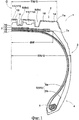
На Фиг.1 представлен вид поперечного сечения большегрузной шины в соответствии с настоящим изобретением, демонстрирующий нормально накаченное ненагруженное состояние шины.1 is a cross-sectional view of a heavy-duty tire in accordance with the present invention, showing a normally inflated unloaded state of the tire.
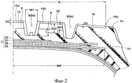
На Фиг.2 представлен увеличенный вид поперечного сечения протектора этой шины.Figure 2 presents an enlarged cross-sectional view of the tread of this tire.
На Фиг.3 представлен развернутый неполный вид сверху большегрузной шины, демонстрирующий протектор.Figure 3 presents a detailed partial top view of a heavy tire showing a tread.
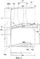
На Фиг.4 представлен неполный вид сверху протектора, демонстрирующий ребро плечевой области.Figure 4 presents an incomplete top view of the tread, showing the rib of the shoulder region.
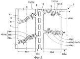
На Фиг.5 представлен вид сверху протектора, демонстрирующий ребра области короны.Figure 5 presents a top view of the tread, showing the ribs of the crown area.
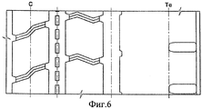
На Фиг.6 представлен развернутый неполный вид сверху большегрузной шины, используемой в указанных ниже сравнительных испытаниях в качестве сравнительного примера Ср.1.Figure 6 presents a detailed partial top view of the heavy truck used in the following comparative tests as a comparative example Cf. 1.
Описание предпочтительных воплощенийDescription of preferred embodiments
При рассмотрении радиальной шины для грузовиков/автобусов в качестве примера воплощения настоящего изобретения описаны далее подробно в совокупности с прилагаемыми чертежами.When considering a radial tire for trucks / buses as an example embodiment of the present invention are described below in detail in conjunction with the accompanying drawings.
В соответствии с настоящим изобретением большегрузная шина 1 включает протектор 2, пару боковин 3, пару бортов 4, каждый с бортовыми кольцами 5 внутри, каркас 6, проходящий между бортами 4 через протектор 2 и боковины 3, и брекерный пояс 7, расположенный снаружи каркаса 6 в протекторе 2 для усиления протектора 2 по существу по всей его ширине.In accordance with the present invention, the heavy-
Каркас 6 состоит из по меньшей мере одного (в данном примере только одного) слоя 6А кордов каркаса, расположенных радиально под углом от 75 до 90 градусов относительно экватора С шины, который проходит между бортами 4 через протектор 2 и боковины 3 и загибается вокруг бортового кольца 5 в каждом борту с внутренней стороны к внешней стороне шины, образуя пару загибов 6b слоя каркаса основную часть 6а слоя каркаса между ними. В данном примере используют стальные корды в качестве кордов каркаса.The
Брекерный пояс 7 состоит из по меньшей мере двух перекрестных слоев 7А и 7В, в данном примере из четырех слоев 7A-7D, включающих два перекрестных слоя 7А и 7В. Каждый из слоев брекерного пояса изготовлен из прорезиненных кордов с высоким модулем упругости, например стальных кордов или т.п., уложенных параллельно друг другу под углом от 15 до 45 градусов относительно экватора С шины.The
Самый широкий слой, определяющий ширину брекерного пояса 7, в данном примере является вторым слоем 7 В, следующим за радиально внутренним первым слоем 7А.The widest layer defining the width of the
В соответствии с настоящим изобретением протектор 2 снабжен четырьмя или пятью продольными канавками 8, проходящими в продольном направлении шины.In accordance with the present invention, the
В воплощении, представленном на чертежах, протектор 2 снабжен четырьмя продольными канавками 8, которые включают: пару плечевых продольных канавок 8s, расположенных с каждой стороны экватора С шины ближе к краю Те протектора, и пару продольных канавок 8с короны, расположенных с каждой стороны экватора С шины и между плечевыми продольными канавками 8s. Таким образом, протектор 2 разделен в аксиальном направлении на пять ребер (кольцевых областей), которые включают: два ребра 14 плечевых областей, каждое из которых ограничено одним из краев Те протектора и одной смежной к нему продольной канавкой 8; и три ребра 11 области короны между двумя ребрами 14 плечевых областей.In the embodiment shown in the drawings, the
В случае протектора 2, снабженного пятью продольными канавками 8, кроме указанных выше плечевых продольных канавок 8s и продольных канавок 8с короны протектор дополнительно снабжен продольной канавкой короны 8с, расположенной на экваторе шины С. Следовательно, протектор 2 разделен в аксиальном направлении на шесть ребер, которые включают указанные выше два ребра 14 плечевых областей и четыре ребра 11 области короны, расположенные между ними.In the case of a
В каждом случае рисунок протектора является двунаправленным рисунком протектора, другими словами, имеющим точечную симметрию относительно любой точки экватора шины.In each case, the tread pattern is a bi-directional tread pattern, in other words, having point symmetry with respect to any point on the tire's equator.
Указанные выше три или четыре ребра 11 области короны включают: пару ребер 11о аксиально-внешней области короны, каждое из которых ограничено смежными с ним плечевой продольной канавкой 8s и продольной канавкой 8с короны, и одно или два ребра 11i аксиально-внутренней области между соседними продольными канавками 8 с короны.The above three or four
Каждое из ребер 11 области короны снабжено поперечными канавками 15 короны, расположенными на расстоянии друг от друга в продольном направлении шины.Each of the
Каждое ребро 14 плечевой области снабжено плечевыми поперечными канавками 18, расположенными на расстоянии друг от друга в продольном направлении шины.Each
Плечевые поперечные канавки 18 расположены с шагом Р в продольном направлении, таким же, как шаг поперечных канавок 15 короны в продольном направлении.The shoulder
Как показано на Фиг.2, по сравнению с продольными канавками 8 поперечные канавки 15 короны и плечевые поперечные канавки 18 очень мелкие.As shown in FIG. 2, in comparison with the
Поперечные канавки 15 короны проходят через всю ширину ребер области 11 короны, следовательно, ребро 11 области короны оказывается разделенным в продольном направлении на ряд блоков 11 В. Но поскольку поперечные канавки 15 короны очень мелкие, как отмечено выше, блоки 11 В короны, в сущности, не отделены друг от друга поперечными канавками 15 короны и в результате ребро 11 области короны сохраняет непрерывность в продольном направлении шины.The
Плечевые поперечные канавки 18 короны проходят от аксиально-внутреннего края 14i ребра 14 плечевой области к аксиально-внешнему краю или краю Те протектора и заканчиваются, не достигая края Те протектора. Соответственно, ребра 14 плечевой области непрерывны в продольном направлении шины по внешнему виду. Более того, благодаря мелким плечевым поперечным канавкам 18 даже в области, снабженной плечевыми поперечными канавками 18, ребра 14 плечевой области сохраняют непрерывность в продольном направлении шины. Таким образом, ребра 14 плечевой области по существу рассматривают как почти непрерывные ребра.The shoulder
Чтобы регулировать или снижать жесткость ребер 11 области короны, предпочтительным является использование ламелей S для изменения глубины поперечных канавок 15. В данном случае ламели S представляют собой прорези или тонкие канавками шириной не более 1,5 мм.In order to adjust or reduce the rigidity of the
Предпочтительно ламели S обеспечены внутри поперечных канавок 15 короны так, что одна ламель S сформирована на дне 15U каждой канавки 15 и проходит вдоль центральной по ширине линии канавки 15.Preferably, the lamellas S are provided inside the
Указанные выше продольные канавки 8 являются по существу прямолинейными канавками.The foregoing
Предпочтительно продольные канавки 8 расположены симметрично относительно экватора шины С.Preferably, the
Например, центральная по ширине линия 10G каждой из плечевых продольных канавок 8s расположена на аксиальном расстоянии L2, составляющем от 19 до 23% ширины TW протектора, аксиально внутрь от края Те протектора.For example, the center-
За исключением продольной канавки 8d короны, расположенной на экваторе шины, центральная по ширине линия 9G каждой продольной канавки 8с короны расположена на аксиальном расстоянии L1, составляющем 8 до 12% ширины TW протектора, от экватора С шины.With the exception of the longitudinal crown groove 8d located at the equator of the tire, the center-wide line 9G of each
Ребра 14 плечевой области имеют аксиальную ширину Ws, а ребра 11 области короны имеют аксиальную ширину Wc (Wc1, Wc2).The
Аксиальная ширина Ws составляет не менее 1,3, предпочтительно не менее 1,35, но не более 1,6, предпочтительно не более 1,5 от значения Wcmin, которое является одним из значений аксиальной ширины Wc, которое не больше, чем любое другое значение ширины Wc.The axial width Ws is not less than 1.3, preferably not less than 1.35, but not more than 1.6, preferably not more than 1.5 of the value of Wcmin, which is one of the values of the axial width Wc, which is not greater than any other value of width Wc.
Отношение Wc2/Wc1 аксиальной ширины Wc2 ребра 11о аксиально-внешней области короны к аксиальной ширине Wc1 ребра 11i аксиально-внутренней области короны составляет от 0,95 до 1,05, чтобы выровнять распределение давления грунта между ребрами области короны.The ratio of the axial width Wc2 / Wc1 of the axial width Wc2 of the rib 11o of the axially external region of the crown to the axial width Wc1 of the
В воплощении, представленном на чертежах, аксиальная ширина Wc1 ребра 11 области короны, расположенного на экваторе шины, меньше, чем аксиальная ширина Wc2 ребер 11 области короны с каждой стороны этого ребра.In the embodiment shown in the drawings, the axial width Wc1 of the
Таким образом, между ребрами 11 и 14 улучшают распределение жесткости, что способствует улучшению сопротивления износу, стабильности прямолинейного движения и характеристик движения на повороте.Thus, between the
Каждая продольная канавка 8 имеет глубину D1 от 15 до 20 мм.Each
Кроме того, каждая продольная канавка 8 имеет ширину W1 не менее 10 мм, предпочтительно не менее 12 мм, но не более 18 мм, предпочтительно не более 16 мм, чтобы улучшить дренаж и жесткость ребер 11 и 14 хорошо сбалансированным образом.In addition, each
Глубина D2 поперечных канавок 15 короны составляет не менее 9%, предпочтительно не менее 10%, но не более 30%, предпочтительно не более 25%, более предпочтительно не более 20% глубины D1 соседней продольной канавки 8.The depth D2 of the
Ширина W2 поперечных канавок 15 короны составляет не менее 2,5 мм, предпочтительно не менее 3,0 мм, но не более 6,0 мм, предпочтительно не более 5,5 мм, чтобы достичь хорошего дренажа и жесткости ребер 11 области короны хорошо сбалансированным образом.The width W2 of the
Предпочтительно ширина W2 постоянна вдоль всей длины поперечной канавки 15 короны.Preferably, the width W2 is constant along the entire length of the
Глубина D3 плечевых поперечных канавок 18 составляет не менее 9%, предпочтительно не менее 10%, но не более 25%, предпочтительно не более 22%, более предпочтительно не более 20% глубины D1 соседней продольной канавки 8.The depth D3 of the
Ширина W3 плечевых поперечных канавок 18 составляет не менее 2,5 мм, предпочтительно не менее 3,0 мм, но не более 6,0 мм, предпочтительно не более 5,5 мм. Предпочтительно ширина W3 равна ширине W2 и постоянна вдоль всей длины плечевой поперечной канавки 18.The width W3 of the
Аксиальная длина L4 плечевой поперечной канавки 18, которую, как показано на Фиг.4, измеряют по центральной по ширине линии канавки от аксиально-внутреннего конца 18i до аксиально-внешнего конца 18о, составляет не менее 78%, предпочтительно не менее 80%, но не более 88%, предпочтительно не более 86% аксиальной ширины Ws ребра 14 плечевой области.The axial length L4 of the shoulder
Таким образом, благодаря описанному выше расположению и строению канавок 8, 15 и 18 жесткость 11 ребра в области короны снижается по сравнению с жесткостью ребра 14 в плечевой области.Thus, due to the location and structure of the
В результате такого распределения жесткости в протекторе 2, энергия трения, приложенная к протектору 2 выравнивается между ребром 14 плечевой области и ребром 11 области короны и, следовательно, возможно регулировать возникновение плечевого износа, а именно, частичного износа, при котором ребро 14 плечевой области изнашивается быстрее, чем другие области.As a result of this stiffness distribution in the
Если глубина D1 продольных канавок 8 составляет более 20 мм, поперечная прочность (жесткость) ребер 11 и 14 снижается и сопротивление износу и стабильность вождения могут ухудшиться. Если глубина D1 составляет менее 15 мм, так как объем канавки снижается, становится трудно обеспечить необходимый дренаж.If the depth D1 of the
Если число продольных канавок 8 менее четырех, становится трудно обеспечить удовлетворительные ходовые характеристики шины на мокром дорожном покрытии. Если число продольных канавок 8 более пяти, так как жесткость ребра снижается, становится трудно улучшить сопротивление износу протектора, в частности сопротивление износу плечевой области.If the number of
Если глубина D2 поперечных канавок 15 короны составляет более 30% глубины D1 продольной канавки 8, тогда жесткость ребра 11 в области короны снижается и сопротивление износу снижается. Если глубина D2 канавки составляет менее 9% глубины 01 канавки, тогда становится трудно улучшить ходовые характеристики на мокром дорожном покрытии.If the depth D2 of the
Если аксиальная ширина Ws ребра 14 плечевой области составляет менее 1,3 значения Wcmin, тогда становится трудно предотвратить трение ребер 14 плечевой области с грунтом, следовательно, может происходить плечевой износ. Если аксиальная ширина Ws составляет более 1,6 значения Wcmin, в центральной области протектора резина протектора может отслаиваться на краях поперечных канавок 15 короны.If the axial width Ws of the
Если глубина D3 плечевых поперечных канавок 18 составляет более 25% глубины D1 продольной канавки 8, тогда жесткость ребер 14 в плечевой области снижается и сопротивление износу снижается. Если глубина D3 канавки составляет менее 9% глубины D1, тогда становится трудно улучшить ходовые характеристики на мокром дорожном покрытии.If the depth D3 of the
Если аксиальная длина L4 плечевых поперечных канавок 18 составляет более 88% аксиальной ширины Ws ребра 14 плечевой области, тогда жесткость ребра 14 плечевой области сильно снижается и становится трудно регулировать плечевой износ. Если аксиальная длина L4 составляет менее 78% аксиальной ширины Ws, возможно возникновение неравномерного износа вдоль плечевых продольных канавок 8s. Более того, становится трудно улучшить ходовые характеристики на мокром дорожном покрытии.If the axial length L4 of the
В каждом ребре 14 плечевой области, как показано на Фиг.4, плечевые поперечные канавки 18 изогнуты по существу на среднем положении 20а по аксиальной ширине Ws ребра 14 плечевой области и плечевые поперечные канавки 18 сформированы в одинаковой конфигурации.In each
Таким образом, плечевая поперечная канавка 18 состоит из аксиально-внутренней части 20, проходящей от аксиально-внутреннего края 14i ребра 14 плечевой области в направлении края Те протектора под углом α4, и аксиально-внешней части 21, проходящей от аксиально-внутренней части 20 в направлении края Те протектора под углом α5, где угол α4 составляет не менее 10 градусов, предпочтительно не менее 12 градусов, но не более 35 градусов, предпочтительно не более 33 градусов относительно аксиального направления шины, и угол α5 составляет от -10 до 10 градусов (от 0 до 10 градусов, если не учитывать направление наклона), предпочтительно не более 9 градусов относительно аксиального направления шины.Thus, the
Поскольку края плечевых поперечных канавок 18 наклонены относительно аксиального направления шины, характеристики сцепления с дорогой в ходе движения на повороте и стабильности вождения могут быть улучшены.Since the edges of the
Если угол α4 аксиально-внутренней части 20 составляет более 35 градусов, тогда угол α3 углового участка 14а между аксиально-внутренней частью 20 и плечевой продольной канавкой 8s становится очень малым и угловой участок 14а может быть подвержен отрыву. Если угол α4 составляет мене 10 градусов, тогда стабильность вождения в ходе движения на повороте не будет улучшена.If the angle α4 of the axial-
Расстояние L3 в продольном направлении между аксиально-внутренним концом 18i и аксиально-внешним концом 18о плечевой поперечной канавки 18, измеренное по центральной по ширине линии 18С этой канавки предпочтительно составляет не менее 10%, более предпочтительно не менее 15%, но не более 30%, более предпочтительно не более 25% продольного шага Р между соседними в продольном направлении плечевыми поперечными канавками 18. Если расстояние L3 в продольном направлении составляет более 30% продольного шага Р, жесткость ребра 14 плечевой области не может быть эффективно снижена и может происходить плечевой износ. Если расстояние L3 в продольном направлении составляет менее 10% продольного шага Р, тогда характеристики сцепления с дорогой в ходе движения на повороте и стабильности вождения не могут быть улучшены.The longitudinal distance L3 between the axially inner end 18i and the axial outer end 18o of the shoulder
Как показано на Фиг.2, с каждой стороны экватора аксиальное расстояние А от аксиально-внешнего конца 18о плечевой поперечной канавки 18 до экватора С шины предпочтительно составляет не менее 95%, более предпочтительно не менее 97%, но не более 105%, более предпочтительно не более 103% аксиального расстояния BW аксиально-внешнего края 7е брекерного пояса 7 от экватора С шины.As shown in FIG. 2, on each side of the equator, the axial distance A from the axially outer end 18o of the shoulder
Применяя такое расположение, всю ширину углубленной части протектора, снабженную плечевыми поперечными канавками и поперечными канавками короны, усиливают, таким образом, неравномерный износ вследствие поперечных канавок (снижение жесткости) можно предотвратить.Using this arrangement, the entire width of the recessed tread portion provided with shoulder lateral grooves and transverse grooves of the crown reinforce, thus, uneven wear due to lateral grooves (reduction in stiffness) can be prevented.
Аксиальное расстояние BW составляет не менее 0,85, предпочтительно не менее 0,86, но не более 0,95, предпочтительно не более 0,94 половины (TW/2) ширины TW протектора.The axial distance BW is not less than 0.85, preferably not less than 0.86, but not more than 0.95, preferably not more than 0.94 half (TW / 2) of the tread width TW.
Если аксиальное расстояние BW составляет менее 0,85 TW/2, нельзя усилить протектор по всей ширине, таким образом, вероятно возникновение неравномерного износа. Если аксиальное расстояние BW составляет более 0,95 TW/2, долговечность боковины протектора может снизиться. Более того, массы шины неблагоприятно возрастает.If the axial distance BW is less than 0.85 TW / 2, the tread cannot be reinforced over the entire width, so uneven wear is likely to occur. If the axial distance BW is more than 0.95 TW / 2, the durability of the tread side may be reduced. Moreover, the tire mass adversely increases.
Глубину указанных выше ламелей S задают так, чтобы она была меньше глубины D1 соседних продольных канавок 8, предпочтительно менее 80% глубины D1. Ламели S проходят по всей ширине ребра и оба их конца открыты.The depth of the above-mentioned slats S is set so that it is less than the depth D1 of the adjacent
Чтобы оптимизировать распределение жесткости в области ребра, на котором обеспечены ламели S, глубину ламелей S снижают на их обоих концах So так, что отношение Ds1/Ds2 глубины Ds1 на открытых концах So к глубине Ds2 в центральной области Si составляет от 0,5 до 0,8.In order to optimize the stiffness distribution in the region of the rib on which the lamellae S are provided, the depth of the lamellas S is reduced at both ends So so that the ratio Ds1 / Ds2 of the depth Ds1 at the open ends of So to the depth Ds2 in the central region Si is from 0.5 to 0 ,8.
По сравнению с шириной SW профиля шины ширину TW протектора задают так, чтобы она была немного шире, чем обычно. А именно, отношение TW/SW ширины TW протектора к ширине SW профиля шины составляет от 0,78 до 0,87. В результате поперечную жесткость шины увеличивают, чтобы улучшить стабильность вождения. Более того, трение ребра плечевой области с грунтом снижают и плечевой износ может быть снижен.Compared to the tire profile width SW, the tread width TW is set to be slightly wider than usual. Namely, the ratio TW / SW of the tread width TW to the tire profile width SW is from 0.78 to 0.87. As a result, the lateral stiffness of the tire is increased to improve driving stability. Moreover, the friction of the ribs of the shoulder region with the soil is reduced and shoulder wear can be reduced.
Если отношение TW/SW составляет менее 0,78, площадь контакта с грунтом становится узкой и сопротивление износу протектора 2 может снижаться. Если отношение TW/SW составляет более 0,87, боковины, особенно в области от положения максимума ширины профиля шины до краев протектора, становятся относительно плоскими и в результате комфортность вождения может ухудшаться.If the TW / SW ratio is less than 0.78, the soil contact area becomes narrow and the wear resistance of the
Как описано выше, поперечные канавки 15 короны и плечевые поперечные канавки 18 очень мелкие, поэтому чтобы эффективно отводить воду из продольных канавок 8 в поперечные канавки 15 и 18, поперечные канавки 15 и 18 проходят радиально внутрь от своих аксиальных концов ко дну продольных канавок 8 вдоль боковых стенок продольных канавок 8 так, что каждая боковая стенка имеет радиально проходящие выемки (В), чередующиеся с по существу плоскими поверхностями (F) боковых стенок.As described above, the
Радиально проходящие выемки (В) в данном примере постепенно увеличиваются по ширине (измеренной в продольном направлении шины) от дна (наиболее глубокая часть, находящаяся в аксиальном направлении шины) к их выходу (в боковую стенку). Таким образом, данная часть (В) имеет практически трапециевидную форму поперечного сечения. Глубина радиально проходящей выемки (В) ограничена в том же диапазоне, как и в поперечной канавке.The radially extending recesses (B) in this example are gradually increasing in width (measured in the longitudinal direction of the tire) from the bottom (the deepest part located in the axial direction of the tire) to their exit (to the side wall). Thus, this part (B) has an almost trapezoidal cross-sectional shape. The depth of the radially extending recess (B) is limited in the same range as in the transverse groove.
В данном воплощении в качестве поперечных канавок 15 используют два типа зигзагообразных канавок, зигзагообразные канавки 16 наклонного типа и зигзагообразные канавки 17 параллельного типа.In this embodiment, two types of zigzag grooves, oblique
Зигзагообразные канавки 16 наклонного типа проходят в виде ломаной линии вдоль наклонной линии, имеющей наклон относительно аксиального направления шины в одном из продольных направлений.
Зигзагообразные канавки 17 параллельного типа проходят в виде ломанной линии вдоль прямой линии, по существу параллельной аксиальному направлению шины.
Более конкретно, зигзагообразные канавки 16 наклонного типа состоят из трех линейных частей, которые представляют собой первую наклонную часть 16А, вторую наклонную часть 16 В и третью наклонную часть 16С, которые наклонены относительно аксиального направления шины в одном из продольных направлений (на чертеже наклон вправо).More specifically, the oblique
Первая наклонная часть 16А проходит от одного аксиального края к другому аксиальному краю ребра 11 области короны, при наклоне под углом α1 относительно аксиального направления шины.The first
Вторая наклонная часть 16В проходит от первой наклонной части 16А к другому аксиальному краю ребра 11 области короны, при наклоне относительно аксиального направления шины под углом α2, большим, чем угол α1.The second
Третья наклонная часть 16С проходит от второй наклонной части 16В к другому аксиальному краю ребра 11 области короны при наклоне относительно аксиального направления шины, под углом α3, меньшим, чем угол α2.The third
Угол α1 составляет от 15 до 25 градусов.The angle α1 is from 15 to 25 degrees.
Угол α2 составляет от 40 до 50 градусов.The angle α2 is from 40 to 50 degrees.
Угол α3 составляет от 15 до 25 градусов.The angle α3 is from 15 to 25 degrees.
Предпочтительно угол α1 равен углу α3.Preferably, the angle α1 is equal to the angle α3.
Зигзагообразные канавки 17 параллельного типа состоят из трех линейных частей, которые представляют собой первую наклонную часть 17А, вторую наклонную часть 17В и третью наклонную часть 17С.The
Первая наклонная часть 17А проходит от одного аксиального края к другому аксиальному краю ребра 11 области короны при наклоне к одному из продольных направлений под углом α6 относительно аксиального направления шины.The first
Вторая наклонная часть 17 В проходит от первой наклонной части 17А к другому аксиальному краю ребра 11 области короны при наклоне в другом продольном направлении, противоположном направлению наклона первой наклонной части 17А, под углом α7 относительно аксиального направления шины.The second
Третья наклонная часть 17С проходит от второй наклонной части 17В к другому аксиальному краю ребра 11 области короны при наклоне к продольному направлению, противоположном направлению наклона второй наклонной части 17В, под углом α8 относительно аксиального направления шины.The third
Угол α6 составляет от 15 до 25 градусов.The angle α6 is from 15 to 25 degrees.
Угол α7 составляет от -15 до -25 градусов.The angle α7 is from -15 to -25 degrees.
Угол α8 составляет от 15 до 20 градусов.The angle α8 is from 15 to 20 degrees.
В данном примере углы α6, α7 и α8 одинаковой величины.In this example, the angles α6, α7, and α8 are the same.
В случае когда протектор снабжен четырьмя продольными канавками 8, как показано на чертежах, предпочтительно поперечные канавки 15 короны, обеспеченные в ребрах 11о аксиально-внешней области короны, представляют собой зигзагообразные канавками 17 параллельного типа, а поперечные канавки 15 короны, обеспеченные на ребре 11i аксиально-внутренней области короны, расположенном на экваторе С шины, представляют собой зигзагообразные канавки 16 наклонного типа.In the case where the tread is provided with four
В случае когда протектор снабжен пятью продольными канавками 8, поперечные канавки 15 короны, обеспеченные на ребрах 11о аксиально-внешней области короны, представляют собой зигзагообразные канавки 17 параллельного типа, а поперечные канавки 15 короны, обеспеченные на ребрах 11i аксиально-внутренней области короны, расположенных с каждой стороны экватора С шины, могут представлять собой зигзагообразные канавки 16 наклонного типа или, в качестве альтернативы, зигзагообразные канавки 17 параллельного типа.In the case where the tread is provided with five
В любом случае предпочтительно поперечные канавки (15, 18) в каждом ребре (11, 14) по существу параллельны друг другу.In any case, preferably the transverse grooves (15, 18) in each rib (11, 14) are substantially parallel to each other.
Более того, чтобы способствовать дренажу от центральной зоны протектора к краям протектора, предпочтительно, чтобы воображаемое продолжение каждой поперечной канавки (15, 18) совпадало с воображаемым продолжением одной из соседних в аксиальном направлении поперечных канавок (15, 18).Moreover, in order to facilitate drainage from the central zone of the tread to the edges of the tread, it is preferable that the imaginary extension of each transverse groove (15, 18) coincides with the imaginary continuation of one of the axially adjacent transverse grooves (15, 18).
Более конкретно, в случае примера, представленного на Фиг.3, аксиально-внутреннее продолжение центральной по ширине линии 15С каждой зигзагообразной канавки 17 параллельного типа (поперечной канавки 15) совпадет с аксиально-внешним продолжением центральной по ширине линии 16С одной из зигзагообразных канавок 16 параллельного типа (поперечных канавок 15) и аксиально-внешнее продолжение центральной по ширине линии 17С указанной выше зигзагообразной канавки 17 параллельного типа (поперечная канавка 15) совпадет с аксиально-внутренним продолжением центральной по ширине линии 18С одной из плечевых поперечных канавок 18.More specifically, in the case of the example of FIG. 3, the axially-internal extension of the parallel center line 15C of each
Благодаря зигзагообразной конфигурации канавок 16 и 17 общая длина краев канавок возрастает и характеристики сцепления с дорогой могут быть улучшены.Due to the zigzag configuration of the
Поскольку зигзагообразные канавки 16 наклонного типа наклонены в одном направлении вращения шины, вода, находящаяся между поверхностью протектора и поверхностью дороги, отводится в направлении канавок 16 и характеристики дренажа улучшаются. Если углы α1, α2 и α3 находятся за пределами указанных выше диапазонов, становится трудно улучшить характеристики дренажа.Since the
Поскольку угол α1 равен углу α3 и угол α6 равен углу α8, жесткость ребра области короны выравнивается между обоими краями в аксиальном направлении шины и возникновение неравномерного износа эффективно регулируют.Since the angle α1 is equal to the angle α3 and the angle α6 is equal to the angle α8, the stiffness of the rib of the crown region is aligned between both edges in the axial direction of the tire and the occurrence of uneven wear is effectively controlled.
Зигзагообразные канавки 16 и 17 снабжены ламелями S вдоль их центральной по ширине линии, а именно, зигзагообразной центральной линии, как описано выше, следовательно, противоположные стенки элементов ребер, которые разделены ламелями, могут сцепляться друг с другом, если подвергаются боковому усилию. В результате ребро действует как непрерывное ребро против прилагаемой поперечной силы и ухудшение стабильности вождения может быть предотвращено.The
Чтобы небольшие объекты, такие как камни на дорогах, не попадали внутрь продольных канавок 8, предпочтительно по меньшей мере продольные канавки 8 с короны снабжены на дне 9U канавки независимыми выступами Н. Выступы Н расположены на расстоянии друг от друга вдоль центральной по ширине линии канавки, и в данном примере выступ Н имеет практически прямоугольную конфигурацию, как показано на Фиг.1 и 2.So that small objects, such as stones on the roads, do not fall into the
Сравнительные испытанияComparative tests
В соответствии с внутренней конструкцией, представленной на Фиг.1, и рисунком протектора, представленном на Фиг.3, изготавливали большегрузные шины размером 295/80R22.5 (размер обода: 22,5×9,00) для грузовиков и автобусов и испытывали на сопротивление плечевому износу и ходовые характеристики на мокром дорожном покрытии.In accordance with the internal structure shown in FIG. 1 and the tread pattern shown in FIG. 3, heavy-duty tires of 295 / 80R22.5 size (rim size: 22.5 × 9.00) were made for trucks and buses and tested on shoulder wear resistance and running characteristics on wet road surfaces.
Все шины имели одинаковую конструкции за исключением характеристик, представленных в таблице 1.All tires had the same design, with the exception of the characteristics shown in table 1.
Испытания ходовых характеристик на мокром дорожном покрытииWet Performance Testing
Испытательный автомобиль (грузовой автомобиль с типом колеса 2DD) с установленными на передние колеса испытываемыми шинами (давление шин 850 кПа) испытывали на круге радиусом 60 метров на мокрой асфальтированной дороге, покрытой водой на глубину 1-2 мм, и измеряли самое быстрое время прохождения пяти кругов. Вертикальная нагрузка шины составляла 50% от нагрузки шины, установленной ETRTO. Обратная величина измеренного времени в секундах представлена в таблице 1 посредством показателя, основанного на этой величине для сравнительного примера Ср.1 принимаемой за 100, причем чем больше величина показателя, тем лучше.A test vehicle (truck with 2DD wheel type) with test tires mounted on the front wheels (tire pressure 850 kPa) was tested on a circle with a radius of 60 meters on a wet asphalt road covered with water to a depth of 1-2 mm, and the fastest driving time of five circles. The vertical tire load was 50% of the tire load set by the ETRTO. The reciprocal of the measured time in seconds is presented in Table 1 by an indicator based on this value for comparative example Cp.1 taken as 100, and the larger the indicator, the better.
Испытания сопротивления плечевому износу: после указанных выше испытаний автомобиль испытывали на дистанции 20000 км, измеряли разность радиуса шины между ребрами 14 плечевой области и ребром 11о аксиально-внешней области короны, чтобы оценить степень плечевого износа.Tests of shoulder wear resistance: after the above tests, the car was tested at a distance of 20,000 km, the difference in the radius of the tire was measured between the
Результаты представлены в таблице 1, где чем меньше величина, тем выше сопротивление плечевому износу.The results are presented in table 1, where the smaller the value, the higher the resistance to shoulder wear.
Из результатов испытаний очевидно, что как сопротивление плечевому износу, так и ходовые характеристики на мокром дорожном покрытии могут быть улучшены.From the test results, it is obvious that both shoulder wear resistance and running performance on wet roads can be improved.
проектора (Фиг.)Picture
projector (Fig.)
11Wed
eleven
проектора (Фиг.)Picture
projector (Fig.)
Общие характеристики:General characteristics:
Ширина протектора TW: 239 мм=80% ширины SW профиля шины Tread width TW: 239 mm = 80% of the width of the tire profile SW
Продольные канавкиLongitudinal grooves
ширина W1:14,0 ммWidth W1: 14.0 mm
глубина D1:16,5 ммdepth D1: 16.5 mm
Продольные канавки короныLongitudinal grooves of the crown
аксиальное расстояние L1 от экватора шины: 9% ширины TWaxial distance L1 from the equator of the tire: 9% of the width TW
протектораtread
Плечевые продольные канавкиShoulder grooves
аксиальное расстояние L2 от экватора шины: 20% ширины TWaxial distance L2 from the equator of the tire: 20% of the width TW
протектораtread
Плечевые поперечные канавкиShoulder lateral grooves
ширина W3:4,0 ммW3 width: 4.0 mm
угол α4:16 градусовα4 angle: 16 degrees
угол α5:0 градусовα5 angle: 0 degrees
продольный шаг Р: 36 мм longitudinal pitch P: 36 mm
Поперечные канавки короныTransverse grooves of the crown
ширина W2:4,0 ммW2 width: 4.0 mm
глубина D2: 12% глубины D1 depth D2: 12% of depth D1
Зигзагообразные канавки 16 наклонного типа
угол α1: 19 градусовangle α1: 19 degrees
угол α2: 44 градусовangle α2: 44 degrees
угол α3: 19 градусов angle α3: 19 degrees
Зигзагообразные канавки 17 параллельного типа
угол α6: 19 градусовα6 angle: 19 degrees
угол α7: 20 градусовα7 angle: 20 degrees
угол α8: 19 градусовα8 angle: 19 degrees
Список обозначенийList of Symbols
2 - Протектор2 - Tread
3 - Боковина3 - Sidewall
4 - Борт4 - Board
5 - Бортовое кольцо5 - Side ring
6 - Каркас6 - Frame
7 - Брекерный пояс7 - belt
8 (8s, 8c) - Продольная канавка (плечевая, короны)8 (8s, 8c) - Longitudinal groove (shoulder, crown)
11 (11i, 11о) - Ребро области короны (внутреннее, внешнее)11 (11i, 11o) - Rib of the crown area (internal, external)
14 - Ребро плечевой области14 - Rib shoulder
15 - Поперечная канавка короны15 - The transverse groove of the crown
16 - Зигзагообразная канавка наклонного типа16 - Inclined Zigzag Groove
17 - Зигзагообразная канавка параллельного типа17 - Zigzag groove parallel type
18 - Плечевая поперечная канавка 18 - Shoulder lateral groove
SW - Ширина профиля шиныSW - Tire Tread Width
Те - Край протектора Those - Edge of the tread
TW - Ширина протектораTW - Tread Width
Claims (6)
протектор с краями протектора, определяющими ширину TW протектора,
пару боковин, определяющих ширину SW поперечного сечения шины,
пару бортов, каждый с бортовым кольцом внутри, каркас, проходящий между бортами через протектор и боковины, и брекерный пояс, состоящий из слоев брекерного пояса, расположенных радиально снаружи каркаса в протекторе, где
ширина TW протектора составляет от 0,78 до 0,87 ширины SW поперечного сечения шины,
протектор снабжен четырьмя или пятью продольными канавками, каждая из которых имеет глубину от 15 до 20 мм и проходит непрерывно в продольном направлении шины так, что в осевом направлении делит протектор на пять или шесть ребер, эти пять или шесть ребер включают пару ребер плечевой области, проходящих вдоль краев протектора и снабженных плечевыми поперечными канавками, и три или четыре ребра области короны, расположенные между плечевыми ребрами и снабженные поперечными канавками короны,
указанные поперечные канавки короны расположены на расстоянии друг от друга в продольном направлении шины и проходят через всю ширину ребра области короны, и глубина поперечных канавок короны составляет от 9 до 30% глубины продольных канавок,
указанные плечевые поперечные канавки расположены на расстоянии друг от друга в продольном направлении шины и проходят аксиально наружу от аксиально-внутреннего края ребра плечевой области так, что заканчиваются на аксиальном расстоянии от 78 до 88% аксиальной ширины ребра плечевой области от указанного аксиально-внутреннего края, и глубина плечевых поперечных канавок составляет от 9 до 25% от глубины продольных канавок.1. Heavy-duty tire, including:
tread with tread edges defining the tread width TW,
a pair of sidewalls defining the width SW of the tire cross section,
a pair of sides, each with a bead ring inside, a frame passing between the sides through the tread and sidewalls, and a belt belt consisting of layers of the belt belt located radially outside the frame in the tread, where
the tread width TW is from 0.78 to 0.87 of the tire cross section width SW,
the tread is provided with four or five longitudinal grooves, each of which has a depth of 15 to 20 mm and runs continuously in the longitudinal direction of the tire so that in the axial direction it divides the tread into five or six ribs, these five or six ribs include a pair of ribs of the shoulder region, passing along the tread edges and provided with shoulder lateral grooves, and three or four ribs of the crown region located between the shoulder ribs and provided with transverse grooves of the crown,
said transverse grooves of the crown are spaced apart from each other in the longitudinal direction of the tire and extend through the entire width of the rib of the crown region, and the depth of the transverse grooves of the crown is from 9 to 30% of the depth of the longitudinal grooves,
said shoulder lateral grooves are spaced apart from one another in the longitudinal direction of the tire and extend axially outward from the axially inner edge of the rib of the shoulder region so that they end at an axial distance of 78 to 88% of the axial width of the rib of the shoulder region from said axially inner edge, and the depth of the shoulder lateral grooves is from 9 to 25% of the depth of the longitudinal grooves.
Applications Claiming Priority (2)
| Application Number | Priority Date | Filing Date | Title |
|---|---|---|---|
| JP2010024644A JP5210334B2 (en) | 2010-02-05 | 2010-02-05 | Heavy duty tire |
| JP2010-024644 | 2010-10-15 |
Publications (2)
| Publication Number | Publication Date |
|---|---|
| RU2011105115A RU2011105115A (en) | 2012-08-10 |
| RU2551699C2 true RU2551699C2 (en) | 2015-05-27 |
Family
ID=43875296
Family Applications (1)
| Application Number | Title | Priority Date | Filing Date |
|---|---|---|---|
| RU2011105115/11A RU2551699C2 (en) | 2010-02-05 | 2011-02-02 | High-capacity tire |
Country Status (8)
| Country | Link |
|---|---|
| US (1) | US8875759B2 (en) |
| EP (1) | EP2357094B1 (en) |
| JP (1) | JP5210334B2 (en) |
| KR (1) | KR101615389B1 (en) |
| CN (1) | CN102145638B (en) |
| AU (1) | AU2010246387B2 (en) |
| BR (1) | BRPI1101764B1 (en) |
| RU (1) | RU2551699C2 (en) |
Families Citing this family (56)
| Publication number | Priority date | Publication date | Assignee | Title |
|---|---|---|---|---|
| FR2972962B1 (en) * | 2011-03-25 | 2013-03-29 | Michelin Soc Tech | OPTIMIZED ROLLER BELT IN WEAR FOR HEAVYWEIGHT TIRE |
| JP5469692B2 (en) * | 2012-02-17 | 2014-04-16 | 住友ゴム工業株式会社 | Pneumatic tire |
| JP5629283B2 (en) * | 2012-03-15 | 2014-11-19 | 住友ゴム工業株式会社 | Pneumatic tire |
| DE112012006301B9 (en) | 2012-07-13 | 2019-11-28 | The Yokohama Rubber Co., Ltd. | tire |
| JP5182455B1 (en) * | 2012-07-13 | 2013-04-17 | 横浜ゴム株式会社 | Pneumatic tire |
| KR101741060B1 (en) * | 2012-07-13 | 2017-05-29 | 요코하마 고무 가부시키가이샤 | Pneumatic tire |
| DE112012006991B4 (en) * | 2012-10-10 | 2019-11-28 | The Yokohama Rubber Co., Ltd. | tire |
| FR2999984B1 (en) * | 2012-12-20 | 2016-02-12 | Michelin & Cie | PNEUMATIC TOP FOR A HEAVY VEHICLE OF GENIE CIVIL TYPE |
| US9987883B2 (en) * | 2012-12-28 | 2018-06-05 | The Yokohama Rubber Co., Ltd. | Pneumatic tire |
| DE112012007276B4 (en) * | 2012-12-28 | 2024-05-02 | The Yokohama Rubber Co., Ltd. | tire |
| WO2014103062A1 (en) * | 2012-12-28 | 2014-07-03 | 横浜ゴム株式会社 | Pneumatic tire |
| JP5798579B2 (en) * | 2013-02-06 | 2015-10-21 | 住友ゴム工業株式会社 | Heavy duty pneumatic tire |
| JP5698775B2 (en) * | 2013-02-08 | 2015-04-08 | 住友ゴム工業株式会社 | Heavy duty pneumatic tire |
| JP5937996B2 (en) * | 2013-04-03 | 2016-06-22 | 住友ゴム工業株式会社 | Heavy duty pneumatic tire |
| US10000094B2 (en) | 2013-08-28 | 2018-06-19 | Bridgestone Corporation | Heavy duty pneumatic tire |
| JP5846227B2 (en) * | 2014-02-06 | 2016-01-20 | 横浜ゴム株式会社 | Pneumatic tire |
| JP6110838B2 (en) * | 2014-11-28 | 2017-04-05 | 住友ゴム工業株式会社 | Heavy duty tire |
| JP6366525B2 (en) * | 2015-02-27 | 2018-08-01 | 東洋ゴム工業株式会社 | Pneumatic tire |
| JP6490542B2 (en) | 2015-08-26 | 2019-03-27 | 住友ゴム工業株式会社 | Heavy duty tire |
| JP6910104B2 (en) * | 2015-10-06 | 2021-07-28 | 横浜ゴム株式会社 | Pneumatic tires |
| EP3176006B1 (en) * | 2015-11-24 | 2018-06-20 | Sumitomo Rubber Industries Limited | Tire |
| FR3044595B1 (en) * | 2015-12-03 | 2017-12-08 | Michelin & Cie | GEOMETRY OF BLOCKS OF A TIRE TREAD FOR TIRES. |
| FR3045485B1 (en) * | 2015-12-16 | 2017-12-22 | Michelin & Cie | PNEUMATIC HAVING IMPROVED WEAR AND ROLL RESISTANCE PROPERTIES |
| FR3045492B1 (en) * | 2015-12-16 | 2017-12-22 | Michelin & Cie | PNEUMATIC HAVING IMPROVED WEAR PROPERTIES |
| FR3045475B1 (en) * | 2015-12-16 | 2017-12-22 | Michelin & Cie | PNEUMATIC HAVING IMPROVED WEAR AND ROLL RESISTANCE PROPERTIES |
| FR3045484B1 (en) * | 2015-12-16 | 2017-12-22 | Michelin & Cie | PNEUMATIC HAVING IMPROVED WEAR AND ROLL RESISTANCE PROPERTIES |
| FR3045489B1 (en) * | 2015-12-16 | 2017-12-22 | Michelin & Cie | PNEUMATIC HAVING IMPROVED WEAR PROPERTIES |
| FR3045477B1 (en) * | 2015-12-16 | 2017-12-22 | Michelin & Cie | PNEUMATIC HAVING IMPROVED WEAR PROPERTIES |
| FR3045469B1 (en) * | 2015-12-16 | 2017-12-22 | Michelin & Cie | PNEUMATIC HAVING IMPROVED WEAR AND ROLL RESISTANCE PROPERTIES |
| FR3045472B1 (en) * | 2015-12-16 | 2017-12-22 | Michelin & Cie | PNEUMATIC HAVING IMPROVED WEAR AND ROLL RESISTANCE PROPERTIES |
| FR3045481B1 (en) * | 2015-12-16 | 2017-12-22 | Michelin & Cie | PNEUMATIC HAVING IMPROVED WEAR AND ROLL RESISTANCE PROPERTIES |
| FR3045474B1 (en) * | 2015-12-16 | 2017-12-22 | Michelin & Cie | PNEUMATIC HAVING IMPROVED WEAR AND ROLL RESISTANCE PROPERTIES |
| USD788025S1 (en) | 2016-03-02 | 2017-05-30 | Bridgestone Americas Tire Operations, Llc | Tire tread |
| JP6699245B2 (en) * | 2016-03-04 | 2020-05-27 | 住友ゴム工業株式会社 | Pneumatic tire |
| FR3051144B1 (en) * | 2016-05-10 | 2018-04-27 | Compagnie Generale Des Etablissements Michelin | PNEUMATIC WORKING LAYER COMPRISING MONOFILAMENTS AND GROOVED ROLLING BELT |
| JP6747055B2 (en) * | 2016-05-19 | 2020-08-26 | 住友ゴム工業株式会社 | Heavy duty tires |
| JP6819213B2 (en) * | 2016-10-26 | 2021-01-27 | 住友ゴム工業株式会社 | Pneumatic tires |
| JP6340057B2 (en) * | 2016-11-01 | 2018-06-06 | 住友ゴム工業株式会社 | Pneumatic tire |
| JP6801386B2 (en) * | 2016-11-11 | 2020-12-16 | 住友ゴム工業株式会社 | Heavy load tires |
| JP6769280B2 (en) * | 2016-12-13 | 2020-10-14 | 住友ゴム工業株式会社 | tire |
| FR3061081A1 (en) * | 2016-12-28 | 2018-06-29 | Compagnie Generale Des Etablissements Michelin | TREAD BAND COMPRISING HIDDEN CAVITIES |
| JP7024360B2 (en) * | 2017-02-08 | 2022-02-24 | 住友ゴム工業株式会社 | Heavy-duty tires and methods for manufacturing heavy-duty tires |
| EP3360699B1 (en) * | 2017-02-08 | 2019-12-04 | Sumitomo Rubber Industries, Ltd. | Heavy duty tire and and method for manufacturing the same |
| JP6850165B2 (en) * | 2017-03-16 | 2021-03-31 | Toyo Tire株式会社 | Pneumatic tires |
| US20190061430A1 (en) * | 2017-08-30 | 2019-02-28 | Sumitomo Rubber Industries, Ltd. | Pneumatic radial tire |
| JP7124546B2 (en) * | 2018-08-09 | 2022-08-24 | 住友ゴム工業株式会社 | pneumatic tire |
| JP7110887B2 (en) * | 2018-10-02 | 2022-08-02 | 住友ゴム工業株式会社 | Heavy duty tire |
| JP7155984B2 (en) * | 2018-12-13 | 2022-10-19 | 住友ゴム工業株式会社 | motorcycle tire |
| JP6658934B2 (en) * | 2019-02-27 | 2020-03-04 | 住友ゴム工業株式会社 | Heavy duty tire |
| JP7290066B2 (en) * | 2019-05-31 | 2023-06-13 | 住友ゴム工業株式会社 | tire |
| JP7121695B2 (en) * | 2019-06-19 | 2022-08-18 | 株式会社ブリヂストン | tire |
| CN111016545B (en) * | 2019-12-31 | 2022-07-26 | 安徽佳通乘用子午线轮胎有限公司 | Radial tire capable of resisting lateral sliding abrasion of tire |
| JP7415156B2 (en) | 2020-01-17 | 2024-01-17 | 横浜ゴム株式会社 | tire |
| JP6996584B2 (en) * | 2020-04-03 | 2022-01-17 | 横浜ゴム株式会社 | tire |
| JP7180771B2 (en) | 2020-04-03 | 2022-11-30 | 横浜ゴム株式会社 | tire |
| CN114987119B (en) * | 2022-04-21 | 2023-10-27 | 安徽佳通乘用子午线轮胎有限公司 | Pneumatic tire |
Citations (4)
| Publication number | Priority date | Publication date | Assignee | Title |
|---|---|---|---|---|
| JP2000168317A (en) * | 1998-12-09 | 2000-06-20 | Bridgestone Corp | Pneumatic tire |
| JP2003063212A (en) * | 2001-08-23 | 2003-03-05 | Bridgestone Corp | Pneumatic tire |
| JP2003118320A (en) * | 2001-10-15 | 2003-04-23 | Sumitomo Rubber Ind Ltd | Pneumatic tire for heavy load |
| EP2055504A1 (en) * | 2007-11-02 | 2009-05-06 | The Yokohama Rubber Co., Ltd. | Pneumatic tire |
Family Cites Families (13)
| Publication number | Priority date | Publication date | Assignee | Title |
|---|---|---|---|---|
| JP3206837B2 (en) * | 1992-09-09 | 2001-09-10 | 住友ゴム工業株式会社 | Pneumatic tire |
| JP2703172B2 (en) | 1992-12-24 | 1998-01-26 | 住友ゴム工業株式会社 | Heavy duty tire |
| JP3204777B2 (en) | 1993-02-18 | 2001-09-04 | オーツタイヤ株式会社 | Pneumatic radial tire for heavy loads |
| FR2728510A1 (en) * | 1994-12-23 | 1996-06-28 | Michelin & Cie | T / H SHAPE TIRE LESS THAN OR EQUAL TO 0.6 |
| FR2754769B1 (en) * | 1996-10-23 | 1998-12-11 | Michelin & Cie | SUMMIT FRAME FOR TIRE-HEAVY TIRE WITH SHAPE RATIO <0.60 |
| IT1288435B1 (en) * | 1997-01-28 | 1998-09-22 | Pirelli | TIRE AND TREAD BAND FOR TIRES PARTICULARLY FOR TRUCKS AND SIMILAR |
| JP4189980B2 (en) * | 1998-11-27 | 2008-12-03 | 株式会社ブリヂストン | Pneumatic tire |
| FR2857621B1 (en) * | 2003-07-18 | 2005-08-19 | Michelin Soc Tech | PNEUMATIC FOR HEAVY VEHICLES |
| JP4583841B2 (en) * | 2004-08-31 | 2010-11-17 | 株式会社ブリヂストン | Pneumatic tire |
| JP4330561B2 (en) * | 2005-07-12 | 2009-09-16 | 住友ゴム工業株式会社 | Heavy duty tire |
| JP5013597B2 (en) * | 2007-03-12 | 2012-08-29 | 株式会社ブリヂストン | Pneumatic tire |
| JP2009248756A (en) * | 2008-04-07 | 2009-10-29 | Bridgestone Corp | Pneumatic tire |
| JP4705684B2 (en) * | 2009-02-06 | 2011-06-22 | 住友ゴム工業株式会社 | Heavy duty tire |
-
2010
- 2010-02-05 JP JP2010024644A patent/JP5210334B2/en active Active
- 2010-11-23 AU AU2010246387A patent/AU2010246387B2/en not_active Ceased
- 2010-11-23 US US12/953,131 patent/US8875759B2/en not_active Expired - Fee Related
- 2010-12-28 KR KR1020100136701A patent/KR101615389B1/en active IP Right Grant
- 2010-12-28 CN CN201010622596.0A patent/CN102145638B/en active Active
-
2011
- 2011-01-10 EP EP11000121.1A patent/EP2357094B1/en active Active
- 2011-02-02 RU RU2011105115/11A patent/RU2551699C2/en active
- 2011-02-07 BR BRPI1101764-3A patent/BRPI1101764B1/en active IP Right Grant
Patent Citations (4)
| Publication number | Priority date | Publication date | Assignee | Title |
|---|---|---|---|---|
| JP2000168317A (en) * | 1998-12-09 | 2000-06-20 | Bridgestone Corp | Pneumatic tire |
| JP2003063212A (en) * | 2001-08-23 | 2003-03-05 | Bridgestone Corp | Pneumatic tire |
| JP2003118320A (en) * | 2001-10-15 | 2003-04-23 | Sumitomo Rubber Ind Ltd | Pneumatic tire for heavy load |
| EP2055504A1 (en) * | 2007-11-02 | 2009-05-06 | The Yokohama Rubber Co., Ltd. | Pneumatic tire |
Also Published As
| Publication number | Publication date |
|---|---|
| EP2357094A3 (en) | 2012-08-22 |
| EP2357094B1 (en) | 2015-03-25 |
| JP5210334B2 (en) | 2013-06-12 |
| BRPI1101764A2 (en) | 2012-07-24 |
| AU2010246387B2 (en) | 2014-10-02 |
| CN102145638B (en) | 2015-03-04 |
| CN102145638A (en) | 2011-08-10 |
| BRPI1101764B1 (en) | 2021-05-25 |
| AU2010246387A1 (en) | 2011-08-25 |
| EP2357094A2 (en) | 2011-08-17 |
| US20110192513A1 (en) | 2011-08-11 |
| RU2011105115A (en) | 2012-08-10 |
| US8875759B2 (en) | 2014-11-04 |
| KR20110091430A (en) | 2011-08-11 |
| JP2011161988A (en) | 2011-08-25 |
| KR101615389B1 (en) | 2016-04-25 |
Similar Documents
| Publication | Publication Date | Title |
|---|---|---|
| RU2551699C2 (en) | High-capacity tire | |
| US10618355B2 (en) | Pneumatic tire | |
| US10343462B2 (en) | Pneumatic tire | |
| US9643457B2 (en) | Pneumatic tire | |
| US10471776B2 (en) | Pneumatic tire | |
| US9221305B2 (en) | Heavy duty pneumatic tire | |
| US9950572B2 (en) | Pneumatic tire | |
| US9434215B2 (en) | Pneumatic tire | |
| US8210219B2 (en) | Pneumatic tire with tread having crown rib and middle ribs | |
| US20180072105A1 (en) | Pneumatic tire | |
| US9505269B2 (en) | Pneumatic tire with tread having central main groove, shoulder main grooves and sipes | |
| US10144250B2 (en) | Heavy duty pneumatic tire | |
| US7918256B2 (en) | Heavy duty tire having ground contacting face at 70% and 100% maximum tire load | |
| US10399390B2 (en) | Pneumatic tire | |
| US8925601B2 (en) | Pneumatic tire | |
| US10486472B2 (en) | Pneumatic tire | |
| US20100200138A1 (en) | Heavy duty tire | |
| US20100269967A1 (en) | Heavy duty radial tire | |
| US9150053B2 (en) | Pneumatic tire | |
| US11325426B2 (en) | Tire | |
| US20150273948A1 (en) | Pneumatic tire | |
| US20130105053A1 (en) | Pneumatic tire | |
| US20180134090A1 (en) | Heavy duty tire | |
| US11731463B2 (en) | Tire |