RU2550373C1 - Method of measurement of threaded connections tightening torque and torque-measuring wrench for its implementation - Google Patents
Method of measurement of threaded connections tightening torque and torque-measuring wrench for its implementation Download PDFInfo
- Publication number
- RU2550373C1 RU2550373C1 RU2014108175/28A RU2014108175A RU2550373C1 RU 2550373 C1 RU2550373 C1 RU 2550373C1 RU 2014108175/28 A RU2014108175/28 A RU 2014108175/28A RU 2014108175 A RU2014108175 A RU 2014108175A RU 2550373 C1 RU2550373 C1 RU 2550373C1
- Authority
- RU
- Russia
- Prior art keywords
- output
- torque
- input
- threaded connection
- pulse counter
- Prior art date
Links
- 238000000034 method Methods 0.000 title claims abstract description 10
- 238000005259 measurement Methods 0.000 title abstract description 9
- 238000009434 installation Methods 0.000 claims description 12
- LHLMOSXCXGLMMN-CLTUNHJMSA-M [(1s,5r)-8-methyl-8-propan-2-yl-8-azoniabicyclo[3.2.1]octan-3-yl] 3-hydroxy-2-phenylpropanoate;bromide Chemical compound [Br-].C([C@H]1CC[C@@H](C2)[N+]1(C)C(C)C)C2OC(=O)C(CO)C1=CC=CC=C1 LHLMOSXCXGLMMN-CLTUNHJMSA-M 0.000 claims 1
- 230000015572 biosynthetic process Effects 0.000 claims 1
- 239000000126 substance Substances 0.000 abstract 1
- 150000001875 compounds Chemical class 0.000 description 1
- 238000010586 diagram Methods 0.000 description 1
- 238000012544 monitoring process Methods 0.000 description 1
Images
Landscapes
- Details Of Spanners, Wrenches, And Screw Drivers And Accessories (AREA)
Abstract
Description
Изобретение относится к измерительной технике и может быть использовано для контроля крутящего момента затяжки резьбовых соединений.The invention relates to measuring technique and can be used to control the tightening torque of threaded connections.
Известен способ измерения крутящего момента затяжки резьбовых соединений, заключающийся в приложении к затянутому резьбовому соединению крутящего момента, перевод резьбового соединения из состояния покоя в состояние движения, поворот на заданный угол, не превышающий 2÷4°, и измерение крутящего момента при достижении углом поворота заданного значения (см. патент RU №2367917, опубл. 20.08. 2009 г.).A known method of measuring the tightening torque of the threaded connections, which consists in applying to the tightened threaded connection the torque, the translation of the threaded connection from the rest state to the motion state, rotation by a predetermined angle not exceeding 2-4 °, and measuring the torque when the rotation angle reaches the specified values (see patent RU No. 2367917, publ. 20.08. 2009).
Однако использование этого способа может привести к значительной перетяжке резьбового соединения, при контроле момента затяжки, что ограничивает использование этого способа.However, the use of this method can lead to a significant constriction of the threaded connection, while controlling the tightening torque, which limits the use of this method.
Технический результат изобретения - расширение технологических возможностей способа путем исключения перетяжки контролируемого соединения.The technical result of the invention is the expansion of technological capabilities of the method by eliminating the constriction of the controlled compound.
Поставленный технический результат достигается тем, что согласно способа измерения крутящего момента затяжки резьбовых соединений, заключающегося в приложении к затянутому резьбовому соединению крутящего момента, перевода резьбового соединения из состояния покоя в состояние движения, поворота на заданный угол, не превышающий 8÷10°, и измерение крутящего момента при достижении углом поворота заданного значения, крутящий момент к резьбовому соединению прикладывается в направлении отвинчивания, измеряется фактический угол, на который произошло отвинчивание резьбового соединения, затем осуществляется поворот резьбового соединения в направлении завинчивания, при повороте резьбового соединения на угол, измеренный при отвинчивании, производится измерение крутящего момента, при этом, измеренное значение крутящего момента будет соответствовать крутящему моменту затяжки резьбового соединения.The technical result achieved is achieved by the fact that according to the method of measuring the tightening torque of the threaded joints, which is applied to the tightened threaded joint of the torque, the threaded joint is transferred from the rest state to the motion state, rotation by a predetermined angle not exceeding 8 ÷ 10 °, and measurement torque when the rotation angle reaches the set value, the torque is applied to the threaded connection in the unscrewing direction, the actual angle is measured, by which roizoshlo unscrewing the threaded connection, then the threaded joint is performed in the direction of screwing rotation, rotating the threaded joint for an angle measured by unscrewing, is measured torque, the measured torque value will correspond to the torque of tightening the threaded joint.
Известен динамометрический ключ, содержащий датчик момента, подключенный ко входу усилителя, выходом соединенного со входом аналого-цифрового преобразователя, первый и второй регистры памяти, информационные выходы аналого-цифрового преобразователя соединены с соответствующими информационными входами первого регистра памяти, датчик угла поворота, первый счетчик импульсов, цифровой индикатор, первый и второй элементы индикации, установочные входы первого регистра памяти и счетчика импульсов через кнопку управления подключены к шине «Напряжение логической единицы» (см. патент RU №2367917 от 20.09.2009 г.).Known torque wrench containing a torque sensor connected to the input of the amplifier, the output connected to the input of the analog-to-digital converter, the first and second memory registers, the information outputs of the analog-to-digital converter are connected to the corresponding information inputs of the first memory register, the rotation angle sensor, the first pulse counter , digital indicator, first and second display elements, installation inputs of the first memory register and pulse counter via a control button connected to the bus "The voltage of the logical unit" (see patent RU No. 2367917 of 09/20/2009).
Недостатком указанного ключа является недостаточно широкие технологические возможности, так как при проверке крутящего момента затяжки резьбовых соединений с высокой угловой жесткостью возможна значительная перетяжка резьбовых соединений, что не всегда допустимо.The disadvantage of this key is not wide enough technological capabilities, since when checking the tightening torque of threaded joints with high angular stiffness, a significant constriction of threaded joints is possible, which is not always permissible.
Технический результат изобретения - расширение технологических возможностей ключа, путем исключения перетяжки при измерениях крутящего момента затяжки резьбовых соединений.The technical result of the invention is the expansion of the technological capabilities of the key by eliminating the constriction when measuring the tightening torque of the threaded joints.
Поставленный технический результат достигается тем, что динамометрический ключ, содержащий датчик момента, подключенный ко входу усилителя, выходом соединенного со входом аналого-цифрового преобразователя, первый и второй регистры памяти, информационные выходы аналого-цифрового преобразователя соединены с соответствующими информационными входами первого регистра памяти, датчик угла поворота, первый счетчик импульсов, цифровой индикатор, первый и второй элементы индикации, установочные входы первого регистра памяти и счетчика импульсов через кнопку управления подключены к шине «Напряжение логической единицы», снабжен вторым счетчиком импульсов, первым и вторым сравнивающими устройствами, первым и вторым триггерами, первым, вторым, третьим и четвертым элементами И, элементом НЕ, третьим элементом индикации и аналоговым компаратором, первым входом подключенного к выходу усилителя, вторым входом - к общей нулевой шине, а выходом - к первым входам первого и второго элементов И, второй вход первого элемента И соединен с выходом датчика угла, а выход - с информационным входом первого счетчика импульсов, информационными выходами подключенный к первым информационным входам первого и второго сравнивающего устройства, вторые информационные входы первого сравнивающего устройства подключены к информационным выходам второго регистра памяти, а выход подключен к S-входу первого триггера, вторые информационные входы второго сравнивающего устройства соединены с информационными выходами второго счетчика импульсов, а выход соединен со входом «Запись» первого регистра памяти и S-входом второго триггера, R-входы первого и второго триггеров и установочный вход второго счетчика импульсов соединены с установочным входом первого счетчика импульсов, выход первого триггера подключен к первому входу третьего элемента И, инверсный выход первого триггера соединен с первым входом четвертого элемента И, вторые входы третьего и четвертого элементов И подключены к инверсному выходу второго триггера, выход третьего элемента И подключен к первому элементу индикации, выход четвертого элемента И подключен ко второму элементу индикации, а выход второго триггера - к третьему элементу индикации, информационный вход второго счетчика импульсов соединен с выходом второго элемента И, вторым входом через элемент НЕ соединенного с выходом аналогового компаратора, а информационные входы цифрового индикатора соединены с информационными выходами первого регистра памяти.The technical result is achieved in that a torque wrench containing a torque sensor connected to the input of the amplifier, an output connected to the input of the analog-to-digital converter, the first and second memory registers, the information outputs of the analog-to-digital converter are connected to the corresponding information inputs of the first memory register, the sensor rotation angle, first pulse counter, digital indicator, first and second display elements, installation inputs of the first memory register and impu meter Through the control button, the wires are connected to the “Logic Unit Voltage” bus, equipped with a second pulse counter, first and second comparison devices, first and second triggers, first, second, third and fourth AND elements, an NOT element, a third indication element and an analog comparator, the first the input of the amplifier connected to the output, the second input to the common zero bus, and the output to the first inputs of the first and second AND elements, the second input of the first AND element is connected to the output of the angle sensor, and the output to the information input the house of the first pulse counter, the information outputs connected to the first information inputs of the first and second comparison devices, the second information inputs of the first comparison device are connected to the information outputs of the second memory register, and the output is connected to the S-input of the first trigger, the second information inputs of the second comparison device information outputs of the second pulse counter, and the output is connected to the “Record” input of the first memory register and the S-input of the second trigger, R-inputs are the first and second triggers and the installation input of the second pulse counter are connected to the installation input of the first pulse counter, the output of the first trigger is connected to the first input of the third element And the inverse output of the first trigger is connected to the first input of the fourth element And, the second inputs of the third and fourth elements And are connected to the inverse output of the second trigger, the output of the third AND element is connected to the first indication element, the output of the fourth AND element is connected to the second indication element, and the output of the second trigger - the third element of the display, second information input of the pulse counter connected to the output of the second AND gate, a second input via NOT element connected to the output of the analog comparator, and the data inputs of the digital indicator connected to data outputs of the first memory register.
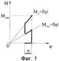
На фиг.1 приведен график зависимости крутящего момента от угла поворота гайки при контроле момента затяжки резьбового соединения.Figure 1 shows a graph of the dependence of torque on the angle of rotation of the nut when monitoring the tightening torque of the threaded connection.
На фиг.3 приведена блок-схема динамометрического ключа.Figure 3 shows a block diagram of a torque wrench.
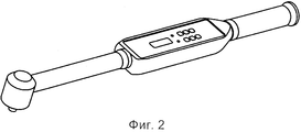
На фиг.2 - общий вид динамометрического ключа.Figure 2 - General view of the torque wrench.
Динамометрический ключ содержит датчик 1 момента, подключенный ко входу усилителя 2, выходом соединенного со входом аналого-цифрового преобразователя 3, первый и второй регистры 4 и 22 памяти, информационные выходы аналого-цифрового преобразователя 3 соединены с соответствующими информационными входами первого регистра 4 памяти, датчик 5 угла поворота, первый счетчик 6 импульсов, цифровой индикатор 7, первый и второй элементы 8 и 9 индикации, установочные входы регистра 4 памяти и счетчика 6 импульсов через кнопку 8 управления подключены к шине 9 «Напряжение логической единицы», второй счетчик 10 импульсов, первое и второе сравнивающее устройство 11 и 12, первый и второй триггеры 13 и 14, первый, второй, третий и четвертый элементы 15, 16, 17 и 18 И, элемент 19 НЕ, третий элемент 20 индикации и аналоговый компаратор 21, первым входом подключенный к выходу усилителя 2, вторым входом - к общей нулевой шине, а выходом - к первым входам первого и второго элементов 15 и 16 И, второй вход первого элемента 15 И соединен с выходом датчика 5 угла, а выход - с информационным входом первого счетчика 6 импульсов, информационными выходами подключенный к первым информационным входам первого и второго сравнивающего устройства 11 и 12, вторые информационные входы первого сравнивающего устройства 11 подключены к информационным выходам второго регистра 22 памяти, а выход подключен к S-входу первого триггера 13, вторые информационные входы второго сравнивающего устройства 12 соединены с информационными выходами второго счетчика 10 импульсов, а выход соединен со входом «Запись» первого регистра 4 памяти и S-входом второго триггера 14, R-входы первого и второго триггеров 13 и 14 и установочный вход второго счетчика 10 импульсов соединены с установочным входом первого счетчика 6 импульсов, выход первого триггера 13 подключен к первому входу третьего элемента 17 И, инверсный выход первого триггера соединен с первым входом четвертого элемента 18 И, вторые входы третьего и четвертого элементов 17 и 18 И подключены к инверсному выходу второго триггера 14, выход третьего элемента 17 И подключен к первому элементу 8 индикации, выход четвертого элемента 18 И подключен ко второму элементу 9 индикации, а выход второго триггера 14 - к третьему элементу 20 индикации, информационный вход второго счетчика 10 импульсов соединен с выходом второго элемента 16 И, вторым входом через элемент 19 НЕ соединенного с выходом аналогового компаратора 21, а информационные входы цифрового индикатора 7 соединены с информационными выходами первого регистра 4 памяти.The torque wrench contains a torque sensor 1 connected to the input of the
Способ измерения крутящего момента затяжки осуществляется следующим образом. На резьбовое соединение одевают ключевую головку динамометрического ключа (не указана) и производят отвинчивание резьбового соединения. При достижении углом поворота установленного значения 8÷10° отвинчивание прекращается и производится измерение фактического угла поворота при отвинчивании. Затем производят поворот резьбового соединения в направлении завинчивания, при повороте резьбового соединения на угол, измеренный при отвинчивании, производится измерение крутящего момента, при этом измеренное значение крутящего момента будет соответствовать крутящему моменту затяжки резьбового соединения. Измерение крутящего момента затяжки закончено.The method of measuring the tightening torque is as follows. On the threaded connection, put on the key head of the torque wrench (not specified) and unscrew the threaded connection. When the angle of rotation reaches the set value of 8 ÷ 10 °, unscrewing stops and the actual angle of rotation is measured when unscrewing. Then, the threaded joint is rotated in the direction of screwing; when the threaded joint is rotated through the angle measured during unscrewing, the torque is measured, while the measured torque value will correspond to the tightening torque of the threaded joint. Tightening torque measurement completed.
Динамометрический ключ работает следующим образом.The torque wrench works as follows.
Ключевой головкой (не указана) ключ устанавливают на резьбовое соединение (не указано) и нажимают кнопку 8 управления. При этом осуществляется сброс содержимого регистра 4 памяти, счетчиков 6 и 7 импульсов и установка триггеров 13 и 14 в нулевое состояние.The key head (not specified), the key is installed on the threaded connection (not specified) and press the control button 8. In this case, the contents of the memory register 4, counters 6 and 7 of the pulses are reset and the triggers 13 and 14 are set to zero.
Это приводит к появлению напряжения логической единицы на выходе элемента 18 И, которое поступает на вход второго элемента 9 индикации.This leads to the appearance of a voltage of a logical unit at the output of the element 18 AND, which is fed to the input of the second element 9 of the display.
Элемент 9 индикации загорается, чем осуществляется индикация о начале отвинчивания.The display element 9 lights up, thereby indicating the start of unscrewing.
Затем к резьбовому соединению прикладывают крутящий момент и переводят резьбовое соединение из состояния покоя в состояние движения и осуществляют его поворот в сторону отвинчивания.Then, a torque is applied to the threaded connection and the threaded connection is transferred from the rest state to the motion state and it is rotated towards unscrewing.
При этом на выходе датчика 1 момента появляется напряжение, величина которого пропорциональна величине приложенного крутящего момента. Это напряжение через усилитель 2 поступает на вход аналого-цифрового преобразователя 3, который осуществляет преобразования напряжения пропорционального моменту в цифровой код. Цифровой код с выходов аналого-цифрового преобразователя 3 поступает на входы регистра 4 памяти.In this case, a voltage appears at the output of the torque sensor 1, the value of which is proportional to the value of the applied torque. This voltage is fed through an
Так как производится отвинчивание резьбового соединения, то на выходе датчика 1 момента напряжение отрицательное. На выходе усилителя 2 напряжение также отрицательное, поэтому на выходе аналогового компаратора 21 напряжение логической единицы. Условие совпадения для элемента 15 И выполняется, выход датчика 5 угла подключен к информационному входу счетчика 6 импульсов, и на вход счетчика 6 начинают поступать импульсы с выхода датчика 5 угла, количество которых соответствует углу поворота резьбового соединения. С информационных выходов счетчика 6 код, соответствующий углу поворота ключа, поступает на вход сравнивающего устройства 11, на вторые входы которого поступает цифровой код с выходов регистра 22 памяти в который предварительно занесен цифровой код, соответствующий требуемому углу отвинчивания.. Когда при повороте резьбового соединения угол поворота достигнет установленного в регистре 22 памяти значения в пределах 8÷10° на выходе сравнивающего устройства 11, появляется импульс, которым триггер 13 устанавливается в единичное состояние. Условие совпадения для элемента 18 И перестает выполнятся, на его выходе напряжение пропадает, индикатор 9 гаснет, чем осуществляется индикация о прекращении отвинчивания и загорается индикатор 8 завинчивание. Оператор прекращает отвинчивание, но до тех пор пока к ключу не будет приложен крутящий момент завинчивания датчик 5 угла продолжает оставаться подключенным ко входу счетчика 6, благодаря чему измеряется фактический угол поворота при отвинчивании.Since the threaded connection is unscrewed, the voltage is negative at the output of the torque sensor 1. At the output of
При завинчивании с выхода датчика 1 момента начинает поступать положительное напряжение, при этом на выходе аналогового компаратора 21 устанавливается напряжение логического нуля, условие совпадения для элемента 15 И перестает выполняться и выход датчика 5 угла отключается от входа счетчика 6 импульсов. При этом на выходах счетчика 6 сохраняется код, соответствующий углу поворота резьбового соединения при отвинчивании. Для элемента 16 И начинает выполнятся условие совпадения, так как на выходе элемента 19 НЕ появляется напряжение логической единицы и на информационный вход счетчика 10 импульсов начинают поступать импульсы с выхода датчика 5 угла, а на выходах счетчика 10 импульсов начинает формироваться цифровой код, соответствующий углу поворота резьбового соединения при завинчивании, который поступает на входы сравнивающего устройства 12. На вторые входы устройства 12 поступает цифровой код, соответствующий углу поворота при отвинчивании, с выходов счетчика 6. Когда при завинчивании угол поворота достигнет величины угла поворота при отвинчивании, на выходе сравнивающего устройства 12 появляется импульс, которым осуществляется запись цифрового кода с выходов аналого-цифрового преобразователя 3, соответствующего величине крутящего момента, в регистр 4 памяти. Код с выходов регистра 4 поступает на входы цифрового индикатора, которым осуществляется индикация измеренной величины крутящего момента. С выхода сравнивающего устройства 12 импульс также поступает на S-вход триггера 14, которым триггер 14 устанавливается в единичное состояние, условие совпадения для элемента 17 И перестает выполнятся, напряжение на его выходе пропадает и элемент 8 индикации гаснет. На выходе триггеров появляется напряжение логической единицы, элемент 20 индикации загорается, чем осуществляется индикация о том, что измерение закончено и цифровой индикатор 7 отображает результат измерения.When screwing from the output of the sensor 1 of the moment, a positive voltage begins to flow, while the output of the analog comparator 21 is set to a logic zero voltage, the matching condition for element 15 is stopped, and the output of the angle sensor 5 is disconnected from the input of the pulse counter 6. At the same time, at the outputs of counter 6, a code is stored corresponding to the angle of rotation of the threaded connection when unscrewing. For element 16 AND, the coincidence condition starts to be fulfilled, since the logical unit voltage does NOT appear at the output of element 19 and pulses from the output of the angle sensor 5 begin to arrive at the information input of the pulse counter 10, and a digital code corresponding to the rotation angle begins to form at the outputs of the pulse counter 10 the screw connection when screwing, which is fed to the inputs of the comparison device 12. At the second inputs of the device 12 receives a digital code corresponding to the angle of rotation when unscrewing, from the outputs account 6. When ika when screwing rotation angle reaches the rotation angle by unscrewing, the output of comparator 12, a pulse, which is performed with the digital code recording outputs the analog-
Измерение крутящего момента затяжки закончено и ключ снимают с проверенного резьбового соединения.The measurement of the tightening torque is completed and the wrench is removed from the tested screw connection.
Введение в динамометрический ключ, содержащий датчик момента, подключенный ко входу усилителя, выходом соединенного со входом аналого-цифрового преобразователя, первый и второй регистры памяти, информационные выходы аналого-цифрового преобразователя соединены с соответствующими информационными входами первого регистра памяти, датчик угла поворота, первый счетчик импульсов, цифровой индикатор, первый и второй элементы индикации, установочные входы первого регистра памяти и счетчика импульсов через кнопку управления подключены к шине «Напряжение логической единицы», второго счетчика импульсов, первого и второго сравнивающего устройства, первого и второго триггера, первого, второго, третьего и четвертого элементов И, элемента НЕ, третьего элемента индикации и аналогового компаратора, первым входом подключенного к выходу усилителя, вторым входом - к общей нулевой шине, а выходом - к первым входам первого и второго элементов И, второй вход первого элемента И соединен с выходом датчика угла, а выход - с информационным входом первого счетчика импульсов, информационными выходами подключенный к первым информационным входам первого и второго сравнивающего устройства, вторые информационные входы первого сравнивающего устройства подключены к информационным выходам второго регистра памяти, а выход подключен к S-входу первого триггера, вторые информационные входы второго сравнивающего устройства соединены с информационными выходами второго счетчика импульсов, а выход соединен со входом «Запись» первого регистра памяти и S-входом второго триггера, R-входы первого и второго триггеров и установочный вход второго счетчика импульсов соединены с установочным входом первого счетчика импульсов, выход первого триггера подключен к первому входу третьего элемента И, инверсный выход первого триггера соединен с первым входом четвертого элемента И, вторые входы третьего и четвертого элементов И подключены к инверсному выходу второго триггера, выход третьего элемента И подключен к первому элементу индикации, выход четвертого элемента И подключен ко второму элементу индикации, а выход второго триггера - к третьему элементу индикации, информационный вход второго счетчика импульсов соединен с выходом второго элемента И, вторым входом через элемент НЕ соединенного с выходом аналогового компаратора, а информационные входы цифрового индикатора соединены с информационными выходами первого регистра памяти. Это позволило расширить технологические возможности ключа.Introduction to a torque wrench containing a torque sensor connected to the amplifier input, output connected to the input of the analog-to-digital converter, the first and second memory registers, information outputs of the analog-to-digital converter connected to the corresponding information inputs of the first memory register, rotation angle sensor, first counter pulses, digital indicator, first and second display elements, installation inputs of the first memory register and pulse counter via a control button connected to the bus e “Voltage of a logical unit”, second pulse counter, first and second comparison device, first and second trigger, first, second, third and fourth elements AND, element NOT, third indication element and analog comparator, the first input connected to the amplifier output, second the input to the common zero bus, and the output to the first inputs of the first and second elements And, the second input of the first element And is connected to the output of the angle sensor, and the output to the information input of the first pulse counter, information outputs the odes connected to the first information inputs of the first and second comparison devices, the second information inputs of the first comparison device are connected to the information outputs of the second memory register, and the output is connected to the S-input of the first trigger, the second information inputs of the second comparison device are connected to the information outputs of the second pulse counter, and the output is connected to the “Record” input of the first memory register and the S-input of the second trigger, the R-inputs of the first and second triggers and the installation input of the second of the first pulse counter are connected to the installation input of the first pulse counter, the output of the first trigger is connected to the first input of the third element And, the inverse output of the first trigger is connected to the first input of the fourth element And, the second inputs of the third and fourth elements And are connected to the inverse output of the second trigger, the output of the third And element is connected to the first indication element, the output of the fourth And element is connected to the second indication element, and the output of the second trigger is connected to the third indication element, information input the second pulse counter is connected to the output of the second AND element, the second input through the element NOT connected to the output of the analog comparator, and the information inputs of the digital indicator are connected to the information outputs of the first memory register. This allowed to expand the technological capabilities of the key.
Claims (2)
Priority Applications (1)
| Application Number | Priority Date | Filing Date | Title |
|---|---|---|---|
| RU2014108175/28A RU2550373C1 (en) | 2014-03-03 | 2014-03-03 | Method of measurement of threaded connections tightening torque and torque-measuring wrench for its implementation |
Applications Claiming Priority (1)
| Application Number | Priority Date | Filing Date | Title |
|---|---|---|---|
| RU2014108175/28A RU2550373C1 (en) | 2014-03-03 | 2014-03-03 | Method of measurement of threaded connections tightening torque and torque-measuring wrench for its implementation |
Publications (1)
| Publication Number | Publication Date |
|---|---|
| RU2550373C1 true RU2550373C1 (en) | 2015-05-10 |
Family
ID=53293953
Family Applications (1)
| Application Number | Title | Priority Date | Filing Date |
|---|---|---|---|
| RU2014108175/28A RU2550373C1 (en) | 2014-03-03 | 2014-03-03 | Method of measurement of threaded connections tightening torque and torque-measuring wrench for its implementation |
Country Status (1)
| Country | Link |
|---|---|
| RU (1) | RU2550373C1 (en) |
Cited By (3)
| Publication number | Priority date | Publication date | Assignee | Title |
|---|---|---|---|---|
| RU2621363C1 (en) * | 2016-04-12 | 2017-06-02 | Закрытое акционерное общество "ИНСТРУМ-РЭНД" | Method of measuring torque threaded joint tightening and dynamometric key for its implementation |
| CN113340512A (en) * | 2021-05-25 | 2021-09-03 | 河南牛帕力学工程研究院 | Method for detecting locking torque between bolt and nut |
| CN114689234A (en) * | 2022-05-27 | 2022-07-01 | 苏州鼎纳自动化技术有限公司 | A kind of static torque automatic detection device and detection method |
Citations (6)
| Publication number | Priority date | Publication date | Assignee | Title |
|---|---|---|---|---|
| SU577415A2 (en) * | 1976-07-02 | 1977-10-25 | Предприятие П/Я В-2616 | Torque meter |
| WO1998038013A1 (en) * | 1997-02-28 | 1998-09-03 | Uirlis Torc Teoranta | A tool incorporating a vibratable handle assembly |
| RU2263290C2 (en) * | 2003-09-18 | 2005-10-27 | Хабрат Николай Иванович | Method of controllable tightening of threaded joints |
| US7320254B1 (en) * | 2004-09-07 | 2008-01-22 | Wendell Martin | Hand-held torque measuring device |
| RU2367917C1 (en) * | 2008-04-07 | 2009-09-20 | ЗАКРЫТОЕ АКЦИОНЕРНОЕ ОБЩЕСТВО "ИНГЕРСОЛЛ-РЭНД СиАйЭс" | Method for measurement of torsion torque of threaded joint tightening and torque spanner for its realisation |
| RU2401423C1 (en) * | 2009-09-01 | 2010-10-10 | Государственное образовательное учреждение высшего профессионального образования "Томский государственный архитектурно-строительный университет" (ГОУВПО "ТГАСУ") | Method to control threaded joint tightening force |
-
2014
- 2014-03-03 RU RU2014108175/28A patent/RU2550373C1/en not_active IP Right Cessation
Patent Citations (6)
| Publication number | Priority date | Publication date | Assignee | Title |
|---|---|---|---|---|
| SU577415A2 (en) * | 1976-07-02 | 1977-10-25 | Предприятие П/Я В-2616 | Torque meter |
| WO1998038013A1 (en) * | 1997-02-28 | 1998-09-03 | Uirlis Torc Teoranta | A tool incorporating a vibratable handle assembly |
| RU2263290C2 (en) * | 2003-09-18 | 2005-10-27 | Хабрат Николай Иванович | Method of controllable tightening of threaded joints |
| US7320254B1 (en) * | 2004-09-07 | 2008-01-22 | Wendell Martin | Hand-held torque measuring device |
| RU2367917C1 (en) * | 2008-04-07 | 2009-09-20 | ЗАКРЫТОЕ АКЦИОНЕРНОЕ ОБЩЕСТВО "ИНГЕРСОЛЛ-РЭНД СиАйЭс" | Method for measurement of torsion torque of threaded joint tightening and torque spanner for its realisation |
| RU2401423C1 (en) * | 2009-09-01 | 2010-10-10 | Государственное образовательное учреждение высшего профессионального образования "Томский государственный архитектурно-строительный университет" (ГОУВПО "ТГАСУ") | Method to control threaded joint tightening force |
Cited By (3)
| Publication number | Priority date | Publication date | Assignee | Title |
|---|---|---|---|---|
| RU2621363C1 (en) * | 2016-04-12 | 2017-06-02 | Закрытое акционерное общество "ИНСТРУМ-РЭНД" | Method of measuring torque threaded joint tightening and dynamometric key for its implementation |
| CN113340512A (en) * | 2021-05-25 | 2021-09-03 | 河南牛帕力学工程研究院 | Method for detecting locking torque between bolt and nut |
| CN114689234A (en) * | 2022-05-27 | 2022-07-01 | 苏州鼎纳自动化技术有限公司 | A kind of static torque automatic detection device and detection method |
Similar Documents
| Publication | Publication Date | Title |
|---|---|---|
| RU2550373C1 (en) | Method of measurement of threaded connections tightening torque and torque-measuring wrench for its implementation | |
| JPS6144582A (en) | Method of discriminating acceptable or defective plastic clamping in nut runner | |
| CN103267605B (en) | A kind of electric wrench torsion angle detection system and method | |
| US11529718B2 (en) | Method and device for tightening screw joints | |
| JPS6363356B2 (en) | ||
| US20180290275A1 (en) | Pulse tool | |
| RU2367917C1 (en) | Method for measurement of torsion torque of threaded joint tightening and torque spanner for its realisation | |
| JP2016505837A (en) | Method and apparatus for evaluating bolt tightening force by ultrasonic means | |
| RU2381098C2 (en) | Method of threaded connection gripping and device for its implementation | |
| CN104931175A (en) | Method for measuring bolt axial fastening force through bolt axial strain | |
| RU2429457C1 (en) | Method of measuring threaded joint tightening force and torque wrench to this end | |
| RU2585907C1 (en) | Digital torque wrench | |
| DE202014105672U1 (en) | Torque and rotation angle tool | |
| RU2579343C1 (en) | Method of tightening threaded joints and device therefor | |
| RU2394214C2 (en) | Stand for monitoring torque of pneumatic nut wrenches | |
| RU2621363C1 (en) | Method of measuring torque threaded joint tightening and dynamometric key for its implementation | |
| RU2400718C2 (en) | Digital torque wrench | |
| RU2598974C1 (en) | Method of tightening threaded connections by torque wrench with rate-of-turn sensor installed in key housing and torque wrench for its implementation | |
| US10668603B2 (en) | Impulse wrench rotation detection | |
| RU2598755C1 (en) | Pneumatic wrench with electronic control of torque | |
| RU2632053C1 (en) | Digital torque wrench | |
| CN206230433U (en) | SCM Based intelligent electric torque spanner | |
| CN110441043B (en) | A sliding wire detection system and method for electric locking screw tools based on motor characteristics | |
| JP6385221B2 (en) | Tightening tool | |
| UA126155C2 (en) | Device for measuring the torque of tightening fasteners |
Legal Events
| Date | Code | Title | Description |
|---|---|---|---|
| MM4A | The patent is invalid due to non-payment of fees |
Effective date: 20170304 |