RU2546993C1 - Method to diagnose technical condition of electric drive by evaluation of dynamics of its electrical parameters - Google Patents
Method to diagnose technical condition of electric drive by evaluation of dynamics of its electrical parameters Download PDFInfo
- Publication number
- RU2546993C1 RU2546993C1 RU2013146260/28A RU2013146260A RU2546993C1 RU 2546993 C1 RU2546993 C1 RU 2546993C1 RU 2013146260/28 A RU2013146260/28 A RU 2013146260/28A RU 2013146260 A RU2013146260 A RU 2013146260A RU 2546993 C1 RU2546993 C1 RU 2546993C1
- Authority
- RU
- Russia
- Prior art keywords
- electric drive
- dynamics
- parameters
- neural network
- drive
- Prior art date
Links
Images
Abstract
Description
Изобретение относится к области диагностики технического состояния электропривода по оценке динамики его параметров и может применяться для диагностики без вывода из работы электроприводов различного типа, эксплуатирующихся в сложных условиях, где затруднен или невозможен постоянный доступ персонала, а также приводов ответственных механизмов, где требуется выявлять аварийные ситуации на ранних стадиях, не повлекших серьезных разрушений.The invention relates to the field of diagnostics of the technical condition of an electric drive by assessing the dynamics of its parameters and can be used for diagnostics without decommissioning electric drives of various types operating in difficult conditions where constant access to personnel is difficult or impossible, as well as drives of critical mechanisms where emergency situations are required in the early stages, without causing serious damage.
Известен способ диагностики технического состояния электродвигателя по его электрическим параметрам, описанный в RU 2425391 C1, G01R 31/34, СПОСОБ ДИАГНОСТИКИ ТЕХНИЧЕСКОГО СОСТОЯНИЯ ЭЛЕКТРОДВИГАТЕЛЯ ПО ЕГО ЭЛЕКТРИЧЕСКИМ ПАРАМЕТРАМ, при котором в трех фазах электродвигателя производят измерение питающего напряжения и фазного тока, а по их сигналам мгновенных значений вычисляют мгновенные значения потребляемых мощностей. Оценку технического состояния двигателя осуществляют по спектрограммам потерь, сравнивая их со спектрограммами потерь, полученных на заведомо исправном двигателе.There is a method for diagnosing the technical condition of an electric motor according to its electrical parameters, described in RU 2425391 C1, G01R 31/34, METHOD FOR DIAGNOSTICS OF THE TECHNICAL CONDITION OF THE ELECTRIC MOTOR BY ITS ELECTRICAL PARAMETERS, in which the voltage, voltage and current are measured in three phases of the electric motor and instantaneous values calculate the instantaneous values of power consumption. Assessment of the technical condition of the engine is carried out according to the spectrograms of losses, comparing them with spectrograms of losses obtained on a known-good engine.
Недостатком этого способа является то, что он позволяет оценивать состояние только самого электродвигателя, без учета искажений, которые могут быть внесены в работу электродвигателя приводным механизмом и питающим преобразователем, что ограничивает виды диагностируемых неисправностей.The disadvantage of this method is that it allows you to evaluate the condition of only the motor itself, without taking into account the distortions that can be introduced into the operation of the electric motor by the drive mechanism and the supply converter, which limits the types of diagnosed faults.
Известен способ определения технического состояния электродвигателя переменного тока и устройство для его осуществления, описанный в RU 2389121 C1, H02K 15/00, G01R 31/34, СПОСОБ ОПРЕДЕЛЕНИЯ ТЕХНИЧЕСКОГО СОСТОЯНИЯ ЭЛЕКТРОДВИГАТЕЛЯ И УСТРОЙСТВО ДЛЯ ЕГО ОСУЩЕСТВЛЕНИЯ, который заключается в получении с датчика в силовой цепи электродвигателя сигнала, его выпрямления и интегрировании в течение установленного времени и измерении. После этого интегрированный сигнал сравнивается с сигналами, полученными аналогично и соответствующими электродвигателю без наработки и с предельной наработкой. По разнице сигналов определяется текущее техническое состояние электродвигателя переменного тока и производится автоматический прогноз остаточного ресурса.A known method for determining the technical condition of an AC motor and a device for its implementation, described in RU 2389121 C1, H02K 15/00, G01R 31/34, METHOD FOR DETERMINING THE TECHNICAL CONDITION OF THE ELECTRIC MOTOR AND DEVICE FOR ITS IMPLEMENTATION, which consists in receiving from the sensor in the power circuit signal electric motor, its rectification and integration during the set time and measurement. After that, the integrated signal is compared with signals obtained in the same way and corresponding to the electric motor without operating hours and with the maximum operating time. The difference in the signals determines the current technical condition of the AC motor and makes an automatic forecast of the residual life.
Недостатком этого способа является то, что он рассчитан на применение только к электродвигателю переменного тока, также не учитывается влияние искажений от приводного механизма и питающего преобразователя на работу электродвигателя. Кроме того, оценка производится только по одному параметру, который не может описать всей динамики объекта, и виды диагностируемых неисправностей ограничены.The disadvantage of this method is that it is designed to be applied only to an alternating current electric motor, and also the influence of distortions from the drive mechanism and the supply converter on the operation of the electric motor is not taken into account. In addition, the assessment is made only on one parameter, which cannot describe the entire dynamics of the object, and the types of diagnosed faults are limited.
Известен способ диагностики механизмов и систем с электрическим приводом (RU 2431152 C2, G01R 31/34, СПОСОБ ДИАГНОСТИКИ МЕХАНИЗМОВ И СИСТЕМ С ЭЛЕКТРИЧЕСКИМ ПРИВОДОМ), взятый за прототип, при котором в течение заданного интервала времени производится запись значений фазных токов и напряжений электродвигателя, после чего производится их разложение на гармонические составляющие с измерением амплитуды и фазы гармонических составляющих, поступающих из сети. После чего производится идентификация технического состояния и прогнозирование ресурса безаварийной работы диагностируемого объекта с помощью искусственной нейронной сети.A known method for diagnosing mechanisms and systems with an electric drive (RU 2431152 C2, G01R 31/34, METHOD FOR DIAGNOSTIC OF MECHANISMS AND SYSTEMS WITH ELECTRIC DRIVE), taken as a prototype, in which during a given time interval the values of phase currents and electric motor voltages are recorded, after what is their decomposition into harmonic components with the measurement of the amplitude and phase of the harmonic components coming from the network. After that, the technical state is identified and the trouble-free operation resource of the diagnosed object is predicted using an artificial neural network.
Недостатком этого способа является то, что не используется информация о скорости и управляющем задании, что не позволяет произвести полноценную идентификацию объекта без предварительных ресурсоемких расчетов гармонических составляющих. Приходится предварительно рассчитывать гармонические составляющие, а нейронная сеть по их составу классифицирует неисправность.The disadvantage of this method is that it does not use information about the speed and control task, which does not allow for the complete identification of the object without preliminary resource-intensive calculations of harmonic components. We have to pre-calculate the harmonic components, and the neural network classifies the malfunction according to their composition.
Технической задачей данного изобретения является создание более эффективного и универсального способа диагностики электроприводов, позволяющего производить оценку технического состояния электропривода в работе на ранней стадии развития дефектов, предупреждая внезапные остановы и снижая затраты на ремонт.The technical task of this invention is the creation of a more efficient and universal method for the diagnosis of electric drives, allowing to evaluate the technical condition of the electric drive in operation at an early stage of development of defects, preventing sudden shutdowns and reducing repair costs.
Технический результат состоит в повышении точности и надежности диагностирования с уменьшением вычислительных затрат на оценку состояния электропривода, за счет применения рекуррентной нейронной сети в качестве основного инструмента анализа состояния электропривода.The technical result consists in increasing the accuracy and reliability of diagnosis with a reduction in computational costs for assessing the state of the electric drive, through the use of a recurrent neural network as the main tool for analyzing the state of the electric drive.
Технический результат достигается тем, что перед эксплуатацией конкретного электропривода, предварительно производится построение его динамической нейросетевой модели, использование которой в дальнейшем позволяет произвести анализ состояния электропривода в работе и удаленно.The technical result is achieved by the fact that before the operation of a particular electric drive, it is preliminarily constructed its dynamic neural network model, the use of which later allows you to analyze the state of the electric drive in operation and remotely.
Сущность изобретения заключается в том, что с определенным интервалом времени производится замер тока, напряжения, скорости и управляющего задания электропривода, преобразование параметров в цифровую форму и передача в персональный компьютер для обработки. Программно реализованная и обученная на конкретном электроприводе перед его эксплуатацией рекуррентная нейронная сеть воспроизводит динамику параметров электропривода, после чего производится сравнение результата динамики нейросетевой модели с реальной динамикой электропривода. В неисправном электроприводе возникает отклонение динамики El(t) его параметров от модели M(t) и рассчитывается функция рассогласования динамики во времени Err(t).The essence of the invention lies in the fact that at a certain time interval, the current, voltage, speed and control task of the electric drive are measured, the parameters are converted to digital form and transferred to a personal computer for processing. A recurrent neural network, programmed and trained on a specific electric drive before its operation, reproduces the dynamics of the parameters of the electric drive, after which the result of the dynamics of the neural network model is compared with the real dynamics of the electric drive. In a faulty electric drive, a deviation of the dynamics El (t) of its parameters from the model M (t) occurs and the function of the dynamics mismatch in time Err (t) is calculated.
![]()
![]()
По характеру динамики Err(t) производится оценка технического состояния и прогноз ресурса электропривода.By the nature of the dynamics of Err (t), the technical condition is estimated and the resource of the drive is forecasted.
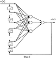
При рассмотрении электропривода как динамического объекта, описываемого вектором входных данных, вектором внутреннего состояния и вектором выходных данных можно получить его модель, применив для идентификации рекуррентную искусственную нейронную. Нейронная сеть, имея достаточное количество обучающих примеров, может быть обучена для воспроизведения динамики объекта согласно теореме об универсальной аппроксимации. Ключевым условием является наличие обратных связей, что позволяет запоминать последовательности сигналов.When considering an electric drive as a dynamic object described by an input data vector, an internal state vector, and an output data vector, we can obtain its model by using a recurrent artificial neural to identify it. Having a sufficient number of training examples, a neural network can be trained to reproduce the dynamics of an object according to the universal approximation theorem. The key condition is the presence of feedback, which allows you to remember the sequence of signals.
Структура нейросетевой модели представлена на Фиг.1.The structure of the neural network model is presented in figure 1.
Обобщенная модель имеет следующее форму:The generalized model has the following form:
![]()
![]()
где ![]()
![]()
![]()
![]()
В настоящее время не существует точного способа определения необходимого числа нейронов, достаточного для оптимальной идентификации объекта по критериям точности отображения и экономии вычислительных ресурсов. Экспериментальным путем было установлено оптимальное применение двухслойной сети с 12 нейронами во внутреннем слое для идентификации электропривода.Currently, there is no exact way to determine the required number of neurons sufficient for optimal identification of an object according to the criteria of display accuracy and saving of computing resources. Experimentally, it was found the optimal use of a two-layer network with 12 neurons in the inner layer to identify the electric drive.
Для сбора информации и осуществления диагностики применяется технический комплекс (Фиг.2) включающий: датчик скорости (ДС), датчик тока (ДТ), датчик напряжения (ДН), измерительно-вычислительный комплекс (ИВК) и персональный компьютер (ПК).To collect information and carry out diagnostics, a technical complex is used (Figure 2) including: a speed sensor (DC), a current sensor (DT), a voltage sensor (DN), a measuring and computing complex (IVK), and a personal computer (PC).
На первом этапе производится идентификация электропривода. Для получения полной информации электропривод запускается во всех режимах работы, в которых в последующем будет эксплуатироваться. При этом производится запись в память ИВК в работе параметров тока с ДТ, напряжения с ДН, скорости с ДС и управляющего задания электропривода, которое формируется самим ИВК.At the first stage, the drive is identified. To obtain complete information, the drive starts up in all operating modes, in which it will subsequently be operated. At the same time, the current parameters with DT, the voltage with DN, the speed with DC and the control task of the electric drive, which is generated by the IVC itself, are recorded in the memory of the IVK in the operation of the current parameters with DT.
После съема данных ИВК приводит их к цифровому виду и производит фильтрацию сигналов скорости W, тока I и напряжения U для устранения шумов методом сглаживания по нескольким точкам.After taking the IVK data, it leads to their digital form and filters the signals of speed W, current I and voltage U to eliminate noise by the method of smoothing at several points.
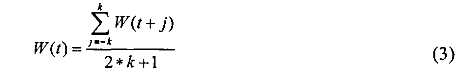
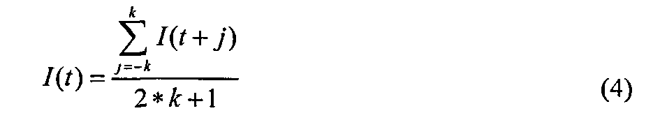

где k - число точек, которые участвуют в сглаживании сигналов.where k is the number of points that are involved in smoothing the signals.
После подготовки данных ИВК передает их в ПК для построения модели. Специальное программное обеспечение осуществляет построение нейросетевой модели (Фиг.1) для идентификации и обучает модель на полученном от ИВК множестве данных. Часть данных резервируется для проверки обученной модели на адекватность отображения динамики.After preparing the data, the CPI transfers them to the PC to build the model. Special software builds a neural network model (Figure 1) for identification and trains the model on the set of data received from the CPI. Part of the data is backed up to test the trained model for adequacy of the dynamics display.
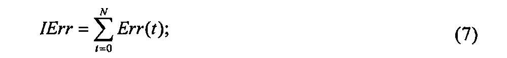
После завершения стадии обучения модели система диагностики может производить вычисления в фоновом режиме, оценивая степень совпадения вектора динамики параметров модели с динамикой параметров электропривода. При этом постоянно вычисляется значение расхождения динамики Err(t), формируя функцию во времени за период t, также ведется расчет интегральной оценки расхождения динамики IErr и скорости изменения расхождения ![]()
![]()
![]()
![]()
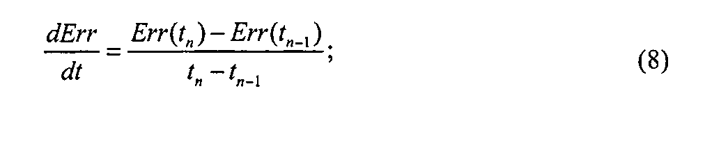
Так как нейросетевая модель имеет некоторую погрешность, то на стадии начальной идентификации вводятся допуски функции ΔErr(t) и ее интегральной оценки ΔIErr, которые принимается за нормальное состояние.Since the neural network model has some error, at the initial identification stage, the tolerances of the function ΔErr (t) and its integral estimate ΔIErr, which are taken as the normal state, are introduced.
После вычисления Err(t), IErr и ![]()
![]()
![]()
![]()
Таким образом, предлагаемая система работает в двух режимах: режиме обучения модели и режиме диагностики. В режиме обучения требуется некоторое время, пока производится съем данных и подготовка формирования обученной нейронной сети, это может занимать порядка 10 минут из-за того что обучение сети ресурсоемко в плане процессорного времени. После обучения система работает в режиме диагностики и расчет текущего состояния динамики и ее оценка занимает мало ресурсов процессора, поэтому способ может быть реализован как на ПК, так целиком и на базе измерительно-вычислительного комплекса ИВК, независимого от ПК или на базе программного обеспечения промышленных контроллеров общего назначения.Thus, the proposed system operates in two modes: model training mode and diagnostic mode. In the training mode, it takes some time until data is taken and preparation of the formation of a trained neural network is carried out, this can take about 10 minutes due to the fact that network training is resource-intensive in terms of processor time. After training, the system operates in the diagnostic mode and calculating the current state of the dynamics and its assessment takes up little processor resources, so the method can be implemented both on a PC and entirely on the basis of the measuring and computing complex of the IVK, independent of the PC or based on the software of industrial controllers general purpose.
Claims (1)
Priority Applications (1)
| Application Number | Priority Date | Filing Date | Title |
|---|---|---|---|
| RU2013146260/28A RU2546993C1 (en) | 2013-10-16 | 2013-10-16 | Method to diagnose technical condition of electric drive by evaluation of dynamics of its electrical parameters |
Applications Claiming Priority (1)
| Application Number | Priority Date | Filing Date | Title |
|---|---|---|---|
| RU2013146260/28A RU2546993C1 (en) | 2013-10-16 | 2013-10-16 | Method to diagnose technical condition of electric drive by evaluation of dynamics of its electrical parameters |
Publications (2)
| Publication Number | Publication Date |
|---|---|
| RU2546993C1 true RU2546993C1 (en) | 2015-04-10 |
| RU2013146260A RU2013146260A (en) | 2015-04-27 |
Family
ID=53282885
Family Applications (1)
| Application Number | Title | Priority Date | Filing Date |
|---|---|---|---|
| RU2013146260/28A RU2546993C1 (en) | 2013-10-16 | 2013-10-16 | Method to diagnose technical condition of electric drive by evaluation of dynamics of its electrical parameters |
Country Status (1)
| Country | Link |
|---|---|
| RU (1) | RU2546993C1 (en) |
Cited By (1)
| Publication number | Priority date | Publication date | Assignee | Title |
|---|---|---|---|---|
| RU2719507C1 (en) * | 2019-12-16 | 2020-04-20 | федеральное государственное бюджетное образовательное учреждение высшего образования "Санкт-Петербургский горный университет" | Method for assessing the technical state of a consumer controller based on neural network diagnosis |
Citations (5)
| Publication number | Priority date | Publication date | Assignee | Title |
|---|---|---|---|---|
| US20030065634A1 (en) * | 2001-07-18 | 2003-04-03 | Texas A&M University System | Method and system for determining induction motor speed |
| US20090091289A1 (en) * | 2007-10-08 | 2009-04-09 | University Of Victoria Innovation And Development Corporation | Stator inter-turn fault detection of synchronous machines |
| US7539549B1 (en) * | 1999-09-28 | 2009-05-26 | Rockwell Automation Technologies, Inc. | Motorized system integrated control and diagnostics using vibration, pressure, temperature, speed, and/or current analysis |
| RU2431152C2 (en) * | 2009-11-23 | 2011-10-10 | Государственное образовательное учреждение высшего профессионального образования "Уфимский государственный нефтяной технический университет" | Method of diagnostics of electrically driven mechanisms and systems |
| RU2495444C1 (en) * | 2012-04-23 | 2013-10-10 | Федеральное государственное бюджетное образовательное учреждение высшего профессионального образования "Национальный исследовательский Томский политехнический университет" | Condition diagnosis method for asynchronous motor |
-
2013
- 2013-10-16 RU RU2013146260/28A patent/RU2546993C1/en not_active IP Right Cessation
Patent Citations (5)
| Publication number | Priority date | Publication date | Assignee | Title |
|---|---|---|---|---|
| US7539549B1 (en) * | 1999-09-28 | 2009-05-26 | Rockwell Automation Technologies, Inc. | Motorized system integrated control and diagnostics using vibration, pressure, temperature, speed, and/or current analysis |
| US20030065634A1 (en) * | 2001-07-18 | 2003-04-03 | Texas A&M University System | Method and system for determining induction motor speed |
| US20090091289A1 (en) * | 2007-10-08 | 2009-04-09 | University Of Victoria Innovation And Development Corporation | Stator inter-turn fault detection of synchronous machines |
| RU2431152C2 (en) * | 2009-11-23 | 2011-10-10 | Государственное образовательное учреждение высшего профессионального образования "Уфимский государственный нефтяной технический университет" | Method of diagnostics of electrically driven mechanisms and systems |
| RU2495444C1 (en) * | 2012-04-23 | 2013-10-10 | Федеральное государственное бюджетное образовательное учреждение высшего профессионального образования "Национальный исследовательский Томский политехнический университет" | Condition diagnosis method for asynchronous motor |
Cited By (1)
| Publication number | Priority date | Publication date | Assignee | Title |
|---|---|---|---|---|
| RU2719507C1 (en) * | 2019-12-16 | 2020-04-20 | федеральное государственное бюджетное образовательное учреждение высшего образования "Санкт-Петербургский горный университет" | Method for assessing the technical state of a consumer controller based on neural network diagnosis |
Also Published As
| Publication number | Publication date |
|---|---|
| RU2013146260A (en) | 2015-04-27 |
Similar Documents
| Publication | Publication Date | Title |
|---|---|---|
| CN108604360B (en) | Facility abnormity monitoring method and system | |
| CN110647133B (en) | Rail transit equipment state detection maintenance method and system | |
| RU2626231C1 (en) | Method of diagnostics of technical condition and electromechanical device remaining lifetime estimation with asynchronous motor | |
| Jardine et al. | A review on machinery diagnostics and prognostics implementing condition-based maintenance | |
| Su et al. | Induction machine condition monitoring using neural network modeling | |
| Ordaz-Moreno et al. | Automatic online diagnosis algorithm for broken-bar detection on induction motors based on discrete wavelet transform for FPGA implementation | |
| Medjaher et al. | Data-driven prognostics based on health indicator construction: Application to PRONOSTIA's data | |
| CN104350435B (en) | The prediction analysis method being embedded in the software platform of programmable logic controller (PLC) | |
| KR102189269B1 (en) | Fault Diagnosis method and system for induction motor using convolutional neural network | |
| USRE45815E1 (en) | Method for simplified real-time diagnoses using adaptive modeling | |
| Medjaher et al. | Feature extraction and evaluation for Health Assessment and Failure prognostics. | |
| KR102545672B1 (en) | Method and apparatus for machine fault diagnosis | |
| Hofmeister et al. | Prognostic health management (PHM) of electrical systems using condition-based data for anomaly and prognostic reasoning | |
| RU2546993C1 (en) | Method to diagnose technical condition of electric drive by evaluation of dynamics of its electrical parameters | |
| Rocchi et al. | Fault prognosis for rotating electrical machines monitoring using recursive least square | |
| CN115683235B (en) | Industrial robot servo motor vibration fault detection method and device | |
| US11339763B2 (en) | Method for windmill farm monitoring | |
| Kruglova et al. | Intelligent Sensorless Fault Diagnosis of Mechatronics Module | |
| RU2451299C1 (en) | Device for on-line diagnostic of electric propulsion system of ship | |
| RU195805U1 (en) | The device for determining the excessive consumption of fuel of ship diesel generator sets | |
| Fumagalli et al. | Agile diagnostic tool based on electrical signature analysis | |
| RU2338215C1 (en) | Method for diagnostics of ac power electric circuit | |
| RU2532762C1 (en) | Method to diagnose and assess residual resource of ac electric drives | |
| CN113516023A (en) | Equipment vibration abnormality diagnosis method and system | |
| RU2799489C1 (en) | Method for determination of technical condition of electric and hydraulic drives |
Legal Events
| Date | Code | Title | Description |
|---|---|---|---|
| MM4A | The patent is invalid due to non-payment of fees |
Effective date: 20161017 |