RU2545503C1 - Method of determination of geometrical displacement of sensors in flat panel detector of x-ray image - Google Patents
Method of determination of geometrical displacement of sensors in flat panel detector of x-ray image Download PDFInfo
- Publication number
- RU2545503C1 RU2545503C1 RU2013150389/28A RU2013150389A RU2545503C1 RU 2545503 C1 RU2545503 C1 RU 2545503C1 RU 2013150389/28 A RU2013150389/28 A RU 2013150389/28A RU 2013150389 A RU2013150389 A RU 2013150389A RU 2545503 C1 RU2545503 C1 RU 2545503C1
- Authority
- RU
- Russia
- Prior art keywords
- sensors
- displacements
- image
- sharp edge
- detector
- Prior art date
Links
- 238000006073 displacement reaction Methods 0.000 title claims abstract description 67
- 238000000034 method Methods 0.000 title claims abstract description 44
- 238000012360 testing method Methods 0.000 claims abstract description 36
- 230000005855 radiation Effects 0.000 claims abstract description 6
- 239000000758 substrate Substances 0.000 claims description 10
- 239000012780 transparent material Substances 0.000 claims description 4
- 239000000126 substance Substances 0.000 abstract 1
- 238000005259 measurement Methods 0.000 description 6
- 238000005457 optimization Methods 0.000 description 5
- 238000002474 experimental method Methods 0.000 description 3
- 238000012546 transfer Methods 0.000 description 3
- 230000009466 transformation Effects 0.000 description 3
- WFKWXMTUELFFGS-UHFFFAOYSA-N tungsten Chemical group [W] WFKWXMTUELFFGS-UHFFFAOYSA-N 0.000 description 3
- 229910052721 tungsten Inorganic materials 0.000 description 3
- 239000010937 tungsten Substances 0.000 description 3
- 230000005540 biological transmission Effects 0.000 description 2
- 238000012937 correction Methods 0.000 description 2
- 230000004907 flux Effects 0.000 description 2
- 239000011159 matrix material Substances 0.000 description 2
- 238000012545 processing Methods 0.000 description 2
- 230000015572 biosynthetic process Effects 0.000 description 1
- 239000002131 composite material Substances 0.000 description 1
- 230000003247 decreasing effect Effects 0.000 description 1
- 238000009826 distribution Methods 0.000 description 1
- 230000014509 gene expression Effects 0.000 description 1
- 239000011521 glass Substances 0.000 description 1
- 238000003702 image correction Methods 0.000 description 1
- 238000004519 manufacturing process Methods 0.000 description 1
- 230000003287 optical effect Effects 0.000 description 1
- 238000000844 transformation Methods 0.000 description 1
- 238000009827 uniform distribution Methods 0.000 description 1
Images


Landscapes
- Analysing Materials By The Use Of Radiation (AREA)
Abstract
Description
Изобретение относится к способам обработки цифровых изображений, в частности к способу определения геометрических смещений сенсоров в плоскопанельном детекторе рентгеновского изображения по изображению тест-объекта.The invention relates to methods for processing digital images, in particular to a method for determining geometric displacements of sensors in a flat-panel x-ray image detector from an image of a test object.
В настоящее время различные производители медицинского оборудования разрабатывают плоскопанельные детекторы рентгеновского излучения с рабочим полем вплоть до нескольких десятков сантиметров. Некоторые из таких детекторов состоят из нескольких сенсоров, жестко закрепленных на общей подложке. Например, в [патент US №6895077, опубл. 17.05.2005] описан рентгеновский аппарат, в котором в качестве возможных вариантов может использоваться детектор из четырех (два на два) или девяти (три на три) ПЗС-сенсоров. В техническом решении [патент US №7663115, опубл. 16.02.2010] описан детектор, состоящий из шести КМОП-сенсоров с рабочим полем 20×30 см. На рентгеновском изображении, полученном с помощью такого составного детектора, в области, соответствующей стыкам сенсоров, присутствуют различного рода артефакты, которые возникают по следующим причинам. Во-первых, сенсоры по своим светочувствительным характеристикам отличаются друг от друга. Во-вторых, в идеальном детекторе между сенсорами не должно быть зазоров и каждый столбец (строка) сенсора должен переходить в соответствующий столбец (строку) соседнего сенсора. Понятно, что в реальных детекторах сенсоры всегда будут геометрически смещены относительно своего идеального положения, что также сказывается на качестве изображения.Currently, various manufacturers of medical equipment are developing flat-panel x-ray detectors with a working field up to several tens of centimeters. Some of these detectors consist of several sensors rigidly mounted on a common substrate. For example, in [US patent No. 6895077, publ. May 17, 2005] an X-ray apparatus is described in which a detector of four (two by two) or nine (three by three) CCD sensors can be used as possible options. In the technical solution [US patent No. 7663115, publ. 02.16.2010] a detector consisting of six CMOS sensors with a working field of 20 × 30 cm is described. On the x-ray image obtained using such a composite detector, in the area corresponding to the joints of the sensors, there are various kinds of artifacts that arise for the following reasons. Firstly, the sensors differ in their photosensitive characteristics. Secondly, in an ideal detector there should be no gaps between the sensors and each column (row) of the sensor should go to the corresponding column (row) of the neighboring sensor. It is clear that in real detectors the sensors will always be geometrically offset relative to their ideal position, which also affects the image quality.
Обе эти причины приводят к заметным артефактам на изображении и к необходимости их коррекции. Для коррекции таких изображений важно понимать также природу таких артефактов и иметь дополнительные измерения, численно характеризующие эти артефакты.Both of these reasons lead to noticeable artifacts in the image and to the need for their correction. To correct such images, it is also important to understand the nature of such artifacts and to have additional dimensions numerically characterizing these artifacts.
Среди способов коррекции изображений известен, например, способ коррекции граничных артефактов в рентгеновском изображении [патент US №8073191, опубл. 06.12.2011], основанный на применении многомерной гипотезы скрытой Марковской модели. В описании к техническому решению указывается, что ширина зоны артефакта может достигать нескольких пикселей, но основное внимание в способе уделяется коррекции собственно артефактов, как таковых.Among the image correction methods, for example, a method for correcting boundary artifacts in an X-ray image is known [US patent No. 8073191, publ. 12/06/2011], based on the application of the multidimensional hypothesis of the hidden Markov model. The description of the technical solution indicates that the width of the artifact zone can reach several pixels, but the main focus of the method is on the correction of the artifacts themselves, as such.
Плоскопанельный детектор представляет собой цельное устройство и в собранном виде не допускает прямого измерения смещений между сенсорами. Поэтому возможны два способа определения геометрических смещений. Первый способ заключается в том, что смещение сенсоров определяется прямым измерением, используя измерительное оборудование, на этапе сборки детектора. Например, оптический микроскоп Galileo AV350 [Galileo AV350 Multi-Sensor Vision System, the L.S. Starrett Company] позволяет проводить измерения расстояний с точностью до нескольких мкм. Второй способ заключается в определении смещений по рентгеновскому изображению тест-объекта.The flat panel detector is a one-piece device and when assembled it does not allow direct measurement of the displacements between the sensors. Therefore, two methods for determining geometric displacements are possible. The first method is that the displacement of the sensors is determined by direct measurement, using measuring equipment, at the detector assembly stage. For example, a Galileo AV350 optical microscope [Galileo AV350 Multi-Sensor Vision System, the L.S. Starrett Company] allows distance measurements to within a few microns. The second method is to determine the displacements from the x-ray image of the test object.
Недостаток прямого измерения смещений заключается в том, что, во-первых, вследствие механических напряжений расположение сенсоров в собранном детекторе может отличаться от значений, измеренных по детектору в разобранном виде. Во-вторых, если необходимо провести такие измерения для уже собранного детектора, то разбирать детектор следует только в специально оборудованном для этого помещении. Обе эти причины практически исключают возможность определения смещений сенсоров за пределами их производства, например в медицинской клинике.The disadvantage of direct measurement of displacements is that, firstly, due to mechanical stresses, the location of the sensors in the assembled detector may differ from the values measured by the detector in disassembled form. Secondly, if it is necessary to carry out such measurements for an already assembled detector, then the detector should be disassembled only in a room specially equipped for this. Both of these reasons practically exclude the possibility of determining the displacements of sensors outside their production, for example, in a medical clinic.
В аналогичных ситуациях, когда нежелательно разбирать устройство, часто используют различные косвенные способы. Например, известен способ определения геометрических смещений сенсоров в сканере по изображению тест-объекта [патент US №6600568, опубл. 29.07.2003]. В этом способе производят сканирование тест-объекта с изображением определенного образа, на скане выбирают участки изображения, соответствующие различным сенсорам, и по их смещениям вычисляют смещения сенсоров.In similar situations, when it is undesirable to disassemble the device, various indirect methods are often used. For example, a method is known for determining the geometric displacements of sensors in a scanner from an image of a test object [US Pat. No. 6,600,568, publ. 07/29/2003]. In this method, a test object is scanned with an image of a specific image, the image sections corresponding to different sensors are selected on the scan, and the displacements of the sensors are calculated from their displacements.
В заявляемом техническом решении рассматривается способ определения геометрических смещений сенсоров в плоскопанельном детекторе рентгеновского излучения по изображению тест-объекта. Экспериментально показана возможность определения геометрических смещений сенсоров по изображению тест-объекта, который включает в себя подложку из рентгенопрозрачного материала и объекты «острый край». В зонах интереса рентгеновского изображения тест-объекта идентифицируют пиксели, соответствующие острому краю каждого объекта «острый край», формируют данные для вычислений и определяют геометрические смещения сенсоров из условия минимума целевого функционала с ограничениями на указанные смещения.The claimed technical solution considers a method for determining the geometric displacements of sensors in a flat-panel x-ray detector from the image of the test object. The possibility of determining the geometric displacements of sensors from the image of a test object, which includes a substrate of X-ray transparent material and objects with a “sharp edge”, has been experimentally shown. In the areas of interest of the X-ray image of the test object, the pixels corresponding to the sharp edge of each object “sharp edge” are identified, the data for calculations are generated and the geometric displacements of the sensors are determined from the condition of the minimum of the target functional with restrictions on the indicated displacements.
Автору не известен из уровня техники способ определения смещения сенсоров, аналогичный заявляемому.The author is not known from the prior art a method for determining the displacement of the sensors, similar to the claimed.
Техническая задача, на решение которой направлено заявляемое изобретение, заключается в расширении арсенала средств определения геометрических смещений сенсоров, а более конкретно, в создании нового способа определения геометрических смещений сенсоров по изображению тест-объекта, позволяющего с достаточной точностью определять смещение сенсоров в плоскопанельном детекторе рентгеновского излучения.The technical problem to be solved by the claimed invention is aimed at expanding the arsenal of means for determining geometric displacements of sensors, and more specifically, in creating a new method for determining geometric displacements of sensors from the image of a test object, which allows with sufficient accuracy to determine the displacement of sensors in a flat-panel x-ray detector .
Техническим результатом является расширение арсенала технических средств определения геометрических смещений сенсоров в плоскопанельном детекторе рентгеновского излучения и возможность определения смещения сенсоров с высокой точностью.The technical result is the expansion of the arsenal of technical means for determining the geometric displacements of sensors in a flat-panel X-ray detector and the ability to determine the displacement of sensors with high accuracy.
Указанный технический результат достигается в способе определения геометрических смещений сенсоров в плоскопанельном детекторе рентгеновского изображения, содержащем по меньшей мере два сенсора, закрепленных на монтажной панели с обеспечением на стыке сенсоров технологического зазора между сенсорами, заключающемся в том, что на рабочей поверхности детектора размещают тест-объект, включающий по меньшей мере два объекта «острый край», соответствующих положению технологического зазора между указанными сенсорами. Поток рентгеновского излучения направляют на тест-объект и получают его рентгеновское изображение. На полученном изображении идентифицируют пиксели, соответствующие изображению острого края каждого объекта «острый край», по которым определяют геометрические смещения сенсоров из условия минимума целевого функционала с линейными и нелинейными ограничениями на указанные смещения. При этом линейные ограничения соответствуют геометрическим смещениям сенсоров, расположенных рядом друг с другом по горизонтали или вертикали, а нелинейные ограничения соответствуют геометрическим смещениям сенсоров, расположенных рядом друг с другом по диагонали.The specified technical result is achieved in a method for determining the geometric displacements of sensors in a flat-panel x-ray image detector containing at least two sensors mounted on a mounting panel to provide a technological gap between the sensors at the junction of the sensors, namely, that a test object is placed on the working surface of the detector comprising at least two objects "sharp edge" corresponding to the position of the technological gap between these sensors. The flow of x-ray radiation is directed to the test object and get its x-ray image. The resulting image identifies the pixels corresponding to the image of the sharp edge of each object "sharp edge", which determine the geometric displacement of the sensors from the minimum condition of the target functional with linear and nonlinear restrictions on these displacements. In this case, linear constraints correspond to geometric displacements of sensors located horizontally or vertically next to each other, and nonlinear constraints correspond to geometric displacements of sensors located diagonally next to each other.
Для идентификации пикселей, соответствующих изображению острого края, вычисляют модуль градиента изображения и идентифицируют пиксели с модулем градиента, выше заданного порогового значения, формируют данные из координат таких пикселей и весовых множителей, при этом в качестве весовых множителей используют модуль градиента пиксела.To identify the pixels corresponding to the sharp-edge image, the image gradient modulus is calculated and pixels with a gradient modulus above a predetermined threshold value are identified, data is generated from the coordinates of such pixels and weight factors, and the pixel gradient module is used as weight factors.
В качестве целевого функционала используют метод наименьших квадратов.The least-squares method is used as the objective functional.
Целесообразно тест-объект выполнить в виде подложки из рентгенопрозрачного материала, на поверхность которой наносят разметку в виде прямолинейных отрезков, соответствующих стыкам сенсоров. Число стыков больше или равно одному в зависимости от числа сенсоров. На каждом из указанных отрезков размещают по крайней мере два объекта «острый край» таким образом, что прямолинейные острые края смежных объектов перпендикулярны друг другу, а угол между острым краем каждого объекта и соответствующим отрезком равен преимущественно сорок пять градусов, причем острые края объектов делят упомянутый отрезок на равные, по существу, части.It is advisable to perform the test object in the form of a substrate of X-ray transparent material, on the surface of which a marking is applied in the form of straight sections corresponding to the joints of the sensors. The number of joints is greater than or equal to one, depending on the number of sensors. At least two “sharp edge” objects are placed on each of these segments so that the rectilinear sharp edges of adjacent objects are perpendicular to each other, and the angle between the sharp edge of each object and the corresponding segment is mainly forty-five degrees, and the sharp edges of the objects divide the aforementioned a segment into essentially equal parts.
Указанная совокупность существенных признаков позволяет достичь технического результата, который заключается в определении геометрических смещений сенсоров с необходимой точностью.The specified set of essential features allows to achieve a technical result, which consists in determining the geometric displacements of the sensors with the necessary accuracy.
Осуществление способа определения геометрических смещений сенсоров плоскопанельного детектора поясняется следующими чертежами.The implementation of the method for determining the geometric displacements of the sensors of a flat panel detector is illustrated by the following drawings.
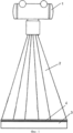
На фиг.1 показано устройство для реализации способа, где позициями обозначены:Figure 1 shows a device for implementing the method, where the positions indicated:
1 - источник рентгеновского излучения;1 - source of x-ray radiation;
2 - поток рентгеновского излучения;2 - x-ray flux;
3 - детектор рентгеновского излучения;3 - X-ray detector;
4 - тест-объект.4 - test object.
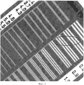
На фиг.2 приведена фотография сенсоров, закрепленных на общей подложке. На фотографии видно, что сенсоры не прилегают плотно друг к другу и между ними присутствуют зазоры. Причем смещения сенсоров относительно заданного положения приводят к тому, что сенсоры оказываются смещены по горизонтали, по вертикали, могут быть также угловые смещения сенсоров, что приводит к образованию технологических зазоров между сенсорами, увеличенных или уменьшенных по сравнению с заданными и неравномерных по ширине.Figure 2 shows a photograph of sensors mounted on a common substrate. The photo shows that the sensors do not fit tightly to each other and there are gaps between them. Moreover, the displacements of the sensors relative to a given position lead to the fact that the sensors are displaced horizontally, there can also be angular displacements of the sensors, which leads to the formation of technological gaps between the sensors, increased or decreased compared to the set and uneven in width.
На фиг.3 представлена увеличенная часть рентгеновского изображения миры на стыке сенсоров детектора. Овалом отмечен участок изображения, на котором артефакты в зоне стыков сенсоров наиболее заметны.Figure 3 presents an enlarged part of the X-ray image of the worlds at the junction of the sensors of the detector. The oval marks the portion of the image in which artifacts in the area of the joints of the sensors are most noticeable.
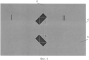
На фиг.4 приведено схематическое изображение тест-объекта 4, где позициями обозначены:Figure 4 shows a schematic representation of the
I и II - области изображения, соответствующие сенсорам детектора;I and II - image areas corresponding to the sensors of the detector;
5 - подложка;5 - substrate;
6 - прямолинейный отрезок, соответствующий стыкам сенсоров детектора;6 - a straight line segment corresponding to the joints of the sensors of the detector;
7-8 - объекты «острый край» и соответствующие им зоны интереса.7-8 - objects "sharp edge" and the corresponding zones of interest.
Данный тест-объект предназначен для определения смещений сенсоров детектора, состоящего из двух сенсоров.This test object is designed to determine the displacements of the sensors of a detector consisting of two sensors.
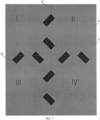
На фиг.5 приведено схематическое изображение тест-объекта 4, где позициями обозначены:Figure 5 shows a schematic representation of the
I-IV - области изображения, соответствующие сенсорам детектора;I-IV - image areas corresponding to the sensors of the detector;
5 - подложка;5 - substrate;
6, 15 - прямолинейные отрезки, соответствующие стыкам сенсоров детектора;6, 15 - straight line segments corresponding to the joints of the detector sensors;
7-14 - объекты «острый край» и соответствующие им зоны интереса.7-14 - objects "sharp edge" and the corresponding zones of interest.
Данный тест-объект предназначен для определения смещений сенсоров детектора, состоящего из четырех сенсоров (два на два сенсора).This test object is designed to determine the displacements of the sensors of the detector, consisting of four sensors (two to two sensors).
На фиг.6 показан модуль градиента изображения объекта «острый край».Figure 6 shows the module gradient image of the object "sharp edge".
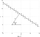
На фиг.7 представлен участок рентгеновского изображения тест-объекта со стыками соседних сенсоров. Точками отмечены пиксели, по которым вычисляют смещения сенсоров. На вертикальной и горизонтальной осях приведена нумерация пикселей.Figure 7 presents the plot of the x-ray image of the test object with the joints of adjacent sensors. Dots mark the pixels by which the displacements of the sensors are calculated. The vertical and horizontal axes show the numbering of pixels.
На фиг.8 приведены пояснения к идентификации прямой по заданному набору точек. Точками обозначен набор данных (x, y), по которым построена прямая с параметрами (p, θ).On Fig. 8, explanations are given for identifying a line by a given set of points. Dots indicate the data set (x, y), on which a straight line with parameters (p, θ) is constructed.
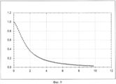
На фиг.9 приведен график функции передачи модуляции детектора, по горизонтали отложены значения пространственных частот в мм-1. На вертикальной оси отложены значения функции передачи модуляции.Figure 9 shows a graph of the transfer function of the modulation of the detector, the horizontal values of spatial frequencies in mm -1 are plotted. The vertical axis represents the values of the modulation transfer function.
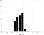
На фиг.10 представлена гистограмма абсолютных ошибок смещений сенсоров по оси x. На горизонтальной оси отложены значения абсолютной ошибки в пикселах, а на вертикальной оси - соответствующие значения вероятности в процентах.Figure 10 presents a histogram of the absolute errors of the displacements of the sensors along the x axis. The horizontal axis represents the absolute error values in pixels, and the vertical axis represents the corresponding probability values in percent.
На фиг.11 представлена гистограмма абсолютных ошибок смещений сенсоров по оси y. На горизонтальной оси отложены значения абсолютной ошибки в пикселах, а на вертикальной оси - соответствующие значения вероятности в процентах.Figure 11 presents a histogram of the absolute errors of the displacements of the sensors along the y axis. The horizontal axis represents the absolute error values in pixels, and the vertical axis represents the corresponding probability values in percent.
Рентгеновское изображение получают с помощью устройства, показанного на фиг.1. Устройство содержит источник рентгеновского излучения 1. Поток рентгеновского излучения 2 направлен на рабочую сторону детектора рентгеновского изображения 3, на которой размещен тест-объект 4. Детектор 3 содержит сцинтилляционный экран (на чертеже не показан), оптически связанный с активной областью детектора. Сцинтилляционный экран преобразует рентгеновское излучение 2 в видимый свет, сенсоры детектора регистрируют его в виде цифрового изображения. Согласно заявляемому способу на рабочей поверхности детектора 3, содержащего по меньшей мере два сенсора, закрепленных на монтажной панели с обеспечением на стыке сенсоров технологического зазора между сенсорами, размещают тест-объект 4 (фиг.4). Поток рентгеновского излучения направляют на рабочую сторону детектора и получают рентгеновское изображение тест-объекта.An x-ray image is obtained using the device shown in figure 1. The device contains an
Опишем способ определения геометрических смещений сенсоров плоскопанельного детектора по рентгеновскому изображению тест-объекта.We describe a method for determining the geometric displacements of the sensors of a flat-panel detector using an X-ray image of a test object.
На рентгеновском изображении изображение острого края должно с достаточной точностью аппроксимироваться прямолинейным отрезком. Суть метода заключается в выполнении следующих этапов:On the x-ray image, the image of the sharp edge should be approximated with sufficient accuracy by a straight line segment. The essence of the method is to perform the following steps:
1) Для каждой зоны интереса формируют набор данных из координат пикселей и весовых множителей, которые соответствуют изображению острого края. В качестве весовых множителей используют модуль градиента соответствующего пиксела.1) For each zone of interest, a data set is formed from the coordinates of the pixels and weight factors that correspond to the image of the sharp edge. As weighting factors, the gradient module of the corresponding pixel is used.
2) Определяют такие преобразования координат, т.е. смещения сенсоров, чтобы точки, соответствующие одному и тому же острому краю, легли на прямую линию с наименьшей ошибкой. В качестве ошибки, т.е. целевого функционала, используют сумму взвешенных квадратов остатков.2) Such coordinate transformations are determined, i.e. sensor displacements so that the points corresponding to the same sharp edge lie on a straight line with the least error. As an error, i.e. target functional, use the sum of the weighted squares of the residuals.
Опишем способ формирования данных для каждой зоны интереса, например позиции 7-14, отмеченные на фиг.5 для детектора из 2×2 сенсоров. Стандартным образом [Р. Гонсалес, Р. Вудс, С. Эддинс, Цифровая обработка изображений в среде MATLAB, Техносфера, 2006., стр.401] вычисляют модуль градиента изображения, используя одномерный линейный фильтр радиуса rLet us describe a method of generating data for each zone of interest, for example, positions 7-14 marked in Fig. 5 for a detector of 2 × 2 sensors. In a standard way [R. Gonzalez, R. Woods, S. Eddins, Digital image processing in MATLAB, Technosphere, 2006., p.401] calculate the image gradient modulus using a one-dimensional linear filter of radius r
Каждому пикселю с координатами (xi, yi) присваивают вес ωI, равный модулю градиента. В последующих вычислениях будем использовать только такие пикселы, веса которых выше заданного порогового значения k×ωmax от максимального значения веса пиксела ωmax в соответствующей зоне интереса. Константа k и параметры линейного фильтра (r, σ) подбирают в ходе численных экспериментов. На фиг.6 приведена часть изображения модуля градиента. На фиг.7 точками отмечены пикселы, веса которых выше заданного порогового значения.Each pixel with coordinates (x i , y i ) is assigned a weight ω I equal to the gradient modulus. In subsequent calculations, we will use only those pixels whose weights are higher than a given threshold value k × ω max of the maximum pixel weight value ω max in the corresponding zone of interest. The constant k and the parameters of the linear filter (r, σ) are selected in the course of numerical experiments. Figure 6 shows a part of the image of the gradient module. 7, pixels are marked with dots whose weights are above a predetermined threshold value.
Опишем способ идентификации прямой на плоскости по данным (xi, yi, ωi), где (xi, γi) - координаты и ωi - веса пикселей. Запишем уравнение прямой (p, θ) в следующем виде:We describe a method for identifying a straight line on a plane according to the data (x i , y i , ω i ), where (x i , γ i ) are the coordinates and ω i are the weights of the pixels. We write the equation of the line (p, θ) in the following form:
p+x×cosθ+y×sinθ=0p + x × cosθ + y × sinθ = 0
Параметры прямой (θ, p) определяют из условия минимума функционалаThe parameters of the straight line (θ, p) are determined from the minimum condition for the functional
![]()
![]()
который есть сумма средневзвешенных квадратов расстояний от каждого пикселя до прямой (θ, p). Этот же функционал можно представить в матричном видеwhich is the sum of the weighted average squares of the distances from each pixel to the line (θ, p). The same functionality can be represented in matrix form
![]()
![]()
здесь τ=(cosθ, sinθ) и Xi=(xi, yi)T. Значения параметров θ и p, доставляющие минимум функционалу E(θ, p), определяются выражениямиhere τ = (cosθ, sinθ) and X i = (x i , y i ) T. The values of the parameters θ and p, delivering a minimum to the functional E (θ, p), are determined by the expressions

где 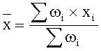
![]()
![]()
Перейдем к описанию следующего этапа определения смещений сенсоров. Для простоты сначала опишем способ определения смещений для детектора типа 1×2 (тест-объект представлен на фиг.4). Пусть ![]()
![]()
![]()
![]()
![]()
![]()
здесь матрица О и вектор D определяют преобразование координат (поворот и смещение) на плоскостиhere the matrix O and the vector D determine the coordinate transformation (rotation and displacement) on the plane
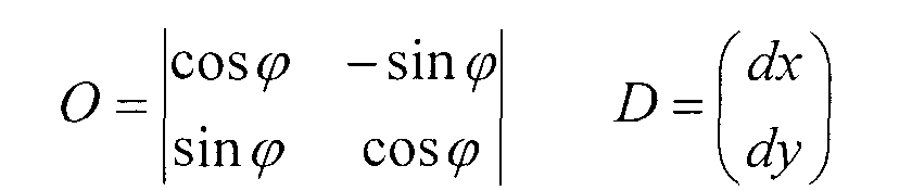
Запишем целевой функционал в видеWe write the target functional in the form

здесь τR=(cosθR, sinθR) и ![]()
![]()
наложить дополнительные ограничения. Поскольку в реальном детекторе углы поворота сенсоров достаточно малы, мы будем считать их равными нулю. Тогда граничные условия записываются особенно просто и получают следующую задачу оптимизации с одним линейным ограничением для x компоненты вектора DII:impose additional restrictions. Since the angle of rotation of the sensors in a real detector is quite small, we will consider them equal to zero. Then the boundary conditions are written especially simply and get the following optimization problem with one linear constraint for the x component of the vector D II :

Перейдем к описанию определения смещений сенсоров для детектора с произвольным числом сенсоров. Пусть N означает число сенсоров по вертикали и M - число сенсоров по горизонтали. Для нумерации сенсоров в детекторе будем использовать мультииндекс (n, m), где n - номер сенсора по вертикали (сверху вниз) и m - номер сенсора по горизонтали (слева направо).Let us turn to the description of the determination of sensor displacements for a detector with an arbitrary number of sensors. Let N mean the number of sensors vertically and M the number of sensors horizontally. To number the sensors in the detector, we will use the multi-index (n, m), where n is the sensor number vertically (from top to bottom) and m is the sensor number horizontally (from left to right).
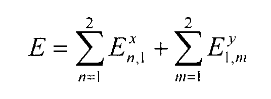
Чтобы определить геометрию детектора с произвольным числом сенсоров, минимизируют целевой функционал следующего вида:To determine the geometry of the detector with an arbitrary number of sensors, minimize the target functional of the following form:
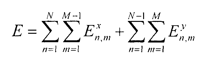
Слагаемые ![]()
![]()
![]()
![]()
![]()
![]()
![]()
![]()
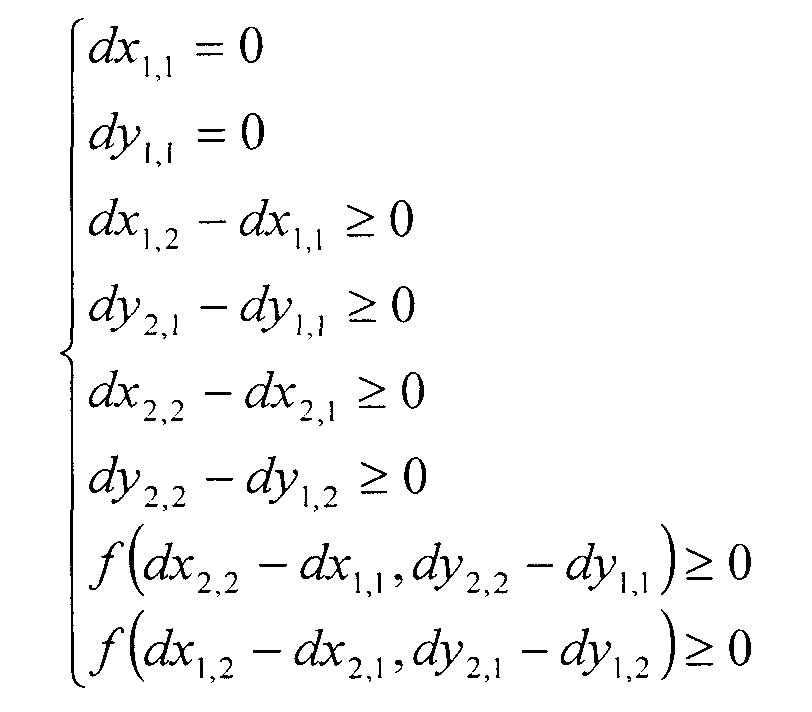
К граничным условиям, вместе с ограничениями по вертикали и горизонтали, следует добавить ограничения для сенсоров, которые расположены на диагонали по отношению друг к другу как, например, сенсоры (1, 1) и (2, 2). В результате получаем следующую задачу оптимизации с линейными и нелинейными ограничениями:To the boundary conditions, together with vertical and horizontal restrictions, we should add restrictions for sensors that are located diagonally with respect to each other, such as sensors (1, 1) and (2, 2). As a result, we obtain the following optimization problem with linear and nonlinear constraints:
E→minE → min
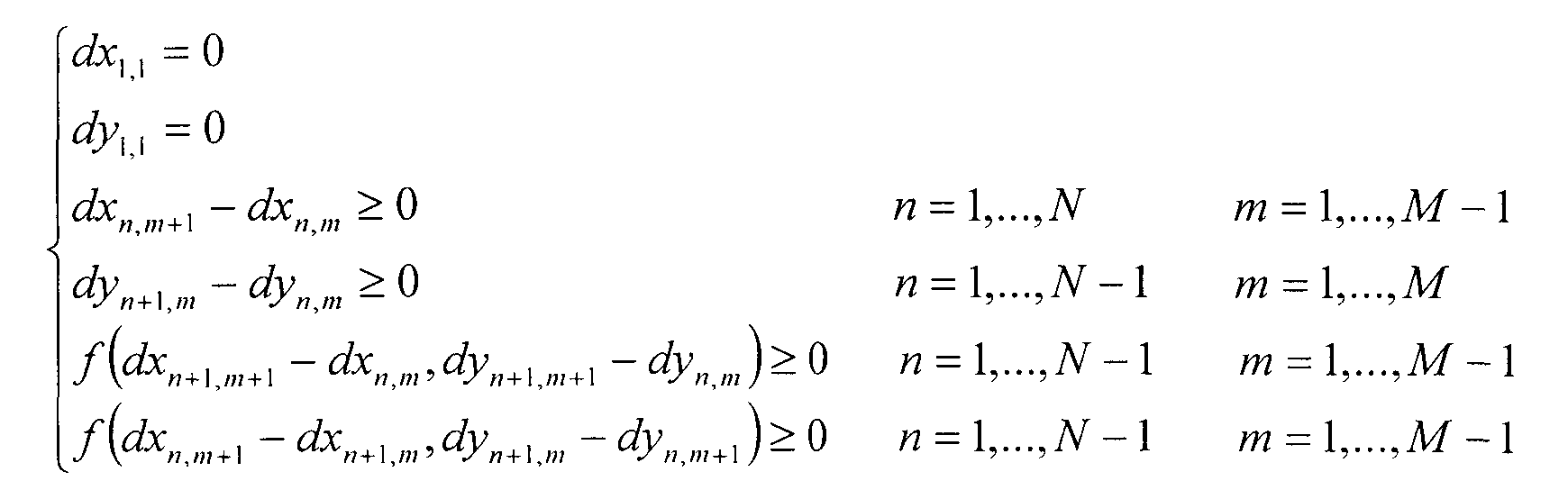
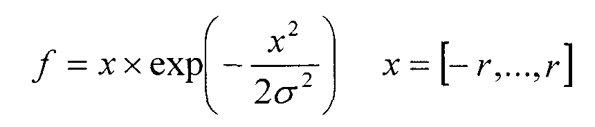
Первые два условия dx1,1=0 и dy1,1=0 появляются вследствие того, что левый верхний сенсор выбран в качестве системы координат, относительно которой производят все вычисления. Третья группа условий dxn,m+1-dxn,m≥0 - суть ограничения для смещений сенсоров, расположенных по горизонтали рядом друг с другом. Четвертая группа условий dxn+1,m-dxn,m≥0 - суть ограничения для смещений сенсоров, расположенных по вертикали рядом друг с другом. Пятая и шестая группы - суть ограничения для сенсоров, которые расположены на диагонали рядом друг с другом. Пятая группа условий - суть ограничения для смещений сенсора (n+1, m+1) по отношению к сенсору (n, m). Шестая группа условий - суть ограничения для смещений сенсора (n+1, m) по отношению к сенсору (n, m+1). В заявляемом способе мы использовали функцию f(x, y) следующего вида:The first two conditions dx 1,1 = 0 and dy 1,1 = 0 appear due to the fact that the upper left sensor is selected as the coordinate system with respect to which all calculations are performed. The third group of conditions dx n, m + 1 -dx n, m ≥0 is the essence of the constraint for displacements of sensors located horizontally next to each other. The fourth group of conditions dx n + 1, m -dx n, m ≥0 is the essence of the constraint for displacements of sensors located vertically next to each other. The fifth and sixth groups are the essence of the restriction for sensors that are located on the diagonal next to each other. The fifth group of conditions is the essence of the constraint for sensor offsets (n + 1, m + 1) with respect to the sensor (n, m). The sixth group of conditions is the essence of the constraint for sensor offsets (n + 1, m) with respect to the sensor (n, m + 1). In the inventive method, we used the function f (x, y) of the following form:
f(x, y}=1-2×logsig(-gain×(x-offset))×logsig(-gain×(y-offset))f (x, y} = 1-2 × logsig (-gain × (x-offset)) × logsig (-gain × (y-offset))
здесь logsig(x)=1/(1+exp(-x)) - сигмоидальная функция. При значениях gain = 100 и offset = 0.01 функция f(x, y) обладает следующими очевидными свойствами:here logsig (x) = 1 / (1 + exp (-x)) is the sigmoid function. For gain = 100 and offset = 0.01, the function f (x, y) has the following obvious properties:
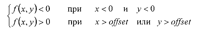
Эти свойства гарантированно исключают пересечение сенсоров, которые лежат на диагонали по отношению друг к другу. Для решения поставленной задачи используют стандартные градиентные методы численной оптимизации с нелинейными ограничениями. В качестве начальных условий для смещений сенсоров при решении поставленной задачи мы использовали следующие значения: ![]()
![]()
![]()
![]()
Для определения смещений сенсоров в плоскопанельном детекторе, состоящем из четырех (два на два) сенсоров, тест-объект 4 (фиг.5) размещают на рабочей поверхности детектора 3. На фиг.5 представлено схематичное изображение тест-объекта, где позициями I-IV обозначены области, соответствующие сенсорам детектора, а позиции 7-14 соответствуют объектам «острый край». Рамками отмечены зоны интереса изображения, по которым вычисляют смещения сенсоров. Тест-объект выполнен в виде подложки 5 из рентгенопрозрачного материала, например органического стекла, размер которой соответствует размеру конкретного детектора 3. На подложке 5 нанесены прямолинейные отрезки 6 и 15. Прямолинейные отрезки 6 и 15 на тест-объекте представляют собой по существу идеальные стыки сенсоров, когда сенсоры были бы размещены без необходимых технологических зазоров в отсутствие смещений сенсоров относительно друг друга. В реальных детекторах при сборке обеспечивают технологические зазоры между сенсорами для предотвращения повреждений сенсоров в результате возможных температурных расширений. Кроме того, из-за неточности при сборке сенсоры геометрически смещаются относительно заданного положения. Прямолинейные отрезки 6 и 15 ориентированы взаимно перпендикулярно и расположены на тест-объекте над заданной областью технологических зазоров. На указанных отрезках размещают и фиксируют объекты «острый край» 7-14, обеспечивая соответствие положения указанных объектов области технологического зазора. Объект «острый край» представляет собой пластину из вольфрама с прямолинейным острым краем. Пластина имеет размеры 20 мм на 10 мм (при размере пиксела детектора 50 мкм) и толщину 1 мм. Выполненную подобным образом пластину используют, например, в тест-объекте для оценки функции передачи модуляции приемников рентгеновского изображения по методу «острого края» (ГОСТ Р МЭК 62220-1-2006). Вольфрамовые пластины размещают на прямолинейных отрезках 6 и 15 подложки 5. Наилучшим вариантом размещения пластин является вариант, когда острые края соседних пластин перпендикулярны друг другу, угол между острым краем каждой пластины и соответствующим прямолинейным отрезком равен, по существу, сорока пяти градусам, острые края пластин делят указанный прямолинейный отрезок на равные по длине части.To determine the displacements of the sensors in a flat-panel detector consisting of four (two by two) sensors, the test object 4 (Fig. 5) is placed on the working surface of the
Чтобы определить геометрию всего детектора в целом, минимизируют целевой функционал следующего вида (N=2 и М=2):To determine the geometry of the entire detector as a whole, minimize the objective functional of the following form (N = 2 and M = 2):
Слагаемое ![]()
![]()
![]()
![]()
![]()
![]()
![]()
![]()
E→minE → min
Первые два условия dx1,1=0 и dy1,1=0 появляются вследствие того, что левый верхний сенсор выбран в качестве системы координат. Третье условие есть ограничение для смещений второго сенсора по отношению к первому сенсору, четвертое - для смещений третьего сенсора по отношению к первому сенсору, пятое и шестое - для смещений четвертого сенсора по отношению ко второму и третьему сенсорам. Седьмое условие есть ограничение для смещений четвертого сенсора по отношению к первому сенсору, и восьмое условие есть ограничение для смещений третьего сенсора по отношению ко второму сенсору. Для решения поставленной задачи используют стандартные градиентные методы численной оптимизации с ограничениями.The first two conditions dx 1,1 = 0 and dy 1,1 = 0 appear due to the fact that the upper left sensor is selected as the coordinate system. The third condition is the restriction for the displacements of the second sensor with respect to the first sensor, the fourth for the displacements of the third sensor with respect to the first sensor, the fifth and sixth for the displacements of the fourth sensor with respect to the second and third sensors. The seventh condition is a restriction for the offsets of the fourth sensor with respect to the first sensor, and the eighth condition is a restriction for the offsets of the third sensor with respect to the second sensor. To solve this problem using standard gradient methods of numerical optimization with restrictions.
Как было отмечено выше, плоскопанельный детектор в собранном виде не допускает прямого измерения смещений сенсоров. По этой причине работоспособность заявляемого способа была проверена на модельных изображениях. В численных экспериментах моделировались 16- разрядные рентгеновские изображения тест-объекта с заранее известным смещением сенсоров со следующими характеристиками изображения:As noted above, an assembled flat panel detector does not allow direct measurement of sensor offsets. For this reason, the performance of the proposed method was tested on model images. In numerical experiments, 16-bit X-ray images of a test object with a previously known sensor displacement with the following image characteristics were simulated:
1) уровень сигнала и шума в области изображения воздуха 30000 и 50 единиц соответственно;1) the signal and noise levels in the air image area are 30,000 and 50 units, respectively;
2) уровень сигнала и шума в области изображения вольфрамовой пластины 650 и 15 единиц соответственно;2) the signal and noise level in the image area of the tungsten plate is 650 and 15 units, respectively;
3) функция передачи модуляции модельных изображений соответствует значениям, измеренным по реальному изображению, и приведена на фиг.9. Методика измерения функции передачи модуляции соответствует стандарту ГОСТ Р МЭК 62220-1-2006.3) the transmission function of the modulation of model images corresponds to the values measured from the real image, and is shown in Fig.9. The methodology for measuring the modulation transfer function complies with GOST R IEC 62220-1-2006.
Шум, накладываемый на модельное изображение, соответствует белому шуму с нормальным распределением. Указанные значения соответствуют реальному рентгеновскому изображению тест-объекта. Смещения сенсоров ![]()
![]()
![]()
![]()
![]()
![]()
![]()
![]()
Использование описываемого способа определения геометрического смещения сенсоров в плоскопанельном детекторе рентгеновского излучения по изображению тест-объекта позволяет просто, эффективно и с высокой точностью проводить оценку геометрического смещения сенсоров без разборки детектора. Предложенный способ расширяет арсенал технических средств определенного назначения.Using the described method for determining the geometric displacement of sensors in a flat-panel x-ray detector from the image of the test object allows you to simply, efficiently and with high accuracy to evaluate the geometric displacement of the sensors without disassembling the detector. The proposed method expands the arsenal of technical means for a specific purpose.
В приведенном выше описании изобретения, охарактеризованном в независимом пункте формулы, показана возможность его осуществления с помощью приведенных в данном описании и известных средств и методов. Следовательно, заявленный способ соответствует условию промышленной применимости.In the above description of the invention, described in an independent claim, the possibility of its implementation using the above-described and known means and methods is shown. Therefore, the claimed method meets the condition of industrial applicability.
Предлагаемое техническое решение раскрыто в описании с возможными примерами его осуществления, которые должны рассматриваться как иллюстрации способа, но не как его ограничение. На основе данного описания специалисты в данной области техники могут предложить другие варианты в рамках изложенной формулы изобретения.The proposed technical solution is disclosed in the description with possible examples of its implementation, which should be considered as illustrations of the method, but not as its limitation. Based on this description, those skilled in the art may suggest other variations within the scope of the appended claims.
Claims (4)
Priority Applications (1)
| Application Number | Priority Date | Filing Date | Title |
|---|---|---|---|
| RU2013150389/28A RU2545503C1 (en) | 2013-11-13 | 2013-11-13 | Method of determination of geometrical displacement of sensors in flat panel detector of x-ray image |
Applications Claiming Priority (1)
| Application Number | Priority Date | Filing Date | Title |
|---|---|---|---|
| RU2013150389/28A RU2545503C1 (en) | 2013-11-13 | 2013-11-13 | Method of determination of geometrical displacement of sensors in flat panel detector of x-ray image |
Publications (1)
| Publication Number | Publication Date |
|---|---|
| RU2545503C1 true RU2545503C1 (en) | 2015-04-10 |
Family
ID=53295415
Family Applications (1)
| Application Number | Title | Priority Date | Filing Date |
|---|---|---|---|
| RU2013150389/28A RU2545503C1 (en) | 2013-11-13 | 2013-11-13 | Method of determination of geometrical displacement of sensors in flat panel detector of x-ray image |
Country Status (1)
| Country | Link |
|---|---|
| RU (1) | RU2545503C1 (en) |
Cited By (1)
| Publication number | Priority date | Publication date | Assignee | Title |
|---|---|---|---|---|
| RU2831756C1 (en) * | 2024-03-28 | 2024-12-13 | Федеральное государственное бюджетное образовательное учреждение высшего образования "Рязанский государственный радиотехнический университет имени В.Ф. Уткина" | Method of correcting geometric distortions of hyperspectral images based on information on roll of scanning sensor when placing hyperspectral equipment on suspension |
Citations (4)
| Publication number | Priority date | Publication date | Assignee | Title |
|---|---|---|---|---|
| SU278186A1 (en) * | X-RAY TELEVISION MEASURING MICROSCOPE | |||
| JP2001353140A (en) * | 2000-06-15 | 2001-12-25 | Shimadzu Corp | X-ray equipment |
| US6600568B1 (en) * | 1998-11-06 | 2003-07-29 | Benq Corporation | System and method of measuring image sensor chip shift |
| JP2009045470A (en) * | 2007-08-14 | 2009-03-05 | Yin-Chao Yao | Direct measurement of interdental distance and positioning and guide ingrowth of oral orthodontic micro-implant |
-
2013
- 2013-11-13 RU RU2013150389/28A patent/RU2545503C1/en active
Patent Citations (4)
| Publication number | Priority date | Publication date | Assignee | Title |
|---|---|---|---|---|
| SU278186A1 (en) * | X-RAY TELEVISION MEASURING MICROSCOPE | |||
| US6600568B1 (en) * | 1998-11-06 | 2003-07-29 | Benq Corporation | System and method of measuring image sensor chip shift |
| JP2001353140A (en) * | 2000-06-15 | 2001-12-25 | Shimadzu Corp | X-ray equipment |
| JP2009045470A (en) * | 2007-08-14 | 2009-03-05 | Yin-Chao Yao | Direct measurement of interdental distance and positioning and guide ingrowth of oral orthodontic micro-implant |
Cited By (1)
| Publication number | Priority date | Publication date | Assignee | Title |
|---|---|---|---|---|
| RU2831756C1 (en) * | 2024-03-28 | 2024-12-13 | Федеральное государственное бюджетное образовательное учреждение высшего образования "Рязанский государственный радиотехнический университет имени В.Ф. Уткина" | Method of correcting geometric distortions of hyperspectral images based on information on roll of scanning sensor when placing hyperspectral equipment on suspension |
Similar Documents
| Publication | Publication Date | Title |
|---|---|---|
| US10775160B2 (en) | System and method for efficient surface measurement using a laser displacement sensor | |
| CN109632085B (en) | Monocular vision-based low-frequency vibration calibration method | |
| US7177740B1 (en) | Method and apparatus for dynamic measuring three-dimensional parameters of tire with laser vision | |
| US8629902B2 (en) | Coordinate fusion and thickness calibration for semiconductor wafer edge inspection | |
| CN106017313B (en) | Edge detection deviation correction value calculation method, edge detection deviation correction method and device | |
| CN108716890A (en) | A kind of high-precision size detecting method based on machine vision | |
| CN107345789A (en) | A kind of pcb board hole location detecting device and method | |
| US20130113897A1 (en) | Process and arrangement for determining the position of a measuring point in geometrical space | |
| CN104266608A (en) | Field calibration device for visual sensor and calibration method | |
| GB2554796A (en) | Testing 3D imaging systems | |
| CN105222727A (en) | The measuring method of linear array CCD camera imaging plane and the worktable depth of parallelism and system | |
| CN103389037B (en) | A kind of illumination diffraction optical element geometric techniques parameter detection device and method | |
| CN112802123A (en) | Binocular linear array camera static calibration method based on stripe virtual target | |
| EA020939B1 (en) | METHOD FOR DETERMINING GEOMETRIC DISPLACEMENTS OF SENSORS IN THE PLANE DETECTOR OF X-RAY IMAGE | |
| CN114111638B (en) | Curved surface detection method based on phase deflection | |
| CN109506629B (en) | A method for calibrating the rotation center of an underwater nuclear fuel assembly detection device | |
| Guo et al. | Research on sub-pixel accuracy flange disk dimension measurement based on machine vision | |
| Yao et al. | Geometric calibration of line-scan camera using a planar pattern | |
| CN115597559B (en) | A Turntable Leveling Method Based on Optical Imaging | |
| CN110874837A (en) | Automatic defect detection method based on local feature distribution | |
| RU2545503C1 (en) | Method of determination of geometrical displacement of sensors in flat panel detector of x-ray image | |
| JP2006276454A (en) | Image correction method and pattern defect inspection method using the same | |
| TWI420229B (en) | Method for measuring modulation transfer function value of lens | |
| EP4205536B1 (en) | Method for measuring dimensions of a plant | |
| CN111141260B (en) | Satellite resolution detection method and system based on three-dimensional spherical target |