RU2541908C1 - Device for decoding signals passing through multibeam communication channel - Google Patents
Device for decoding signals passing through multibeam communication channel Download PDFInfo
- Publication number
- RU2541908C1 RU2541908C1 RU2013150766/08A RU2013150766A RU2541908C1 RU 2541908 C1 RU2541908 C1 RU 2541908C1 RU 2013150766/08 A RU2013150766/08 A RU 2013150766/08A RU 2013150766 A RU2013150766 A RU 2013150766A RU 2541908 C1 RU2541908 C1 RU 2541908C1
- Authority
- RU
- Russia
- Prior art keywords
- stage
- correlators
- correlator
- output
- inputs
- Prior art date
Links
Images
Abstract
Description
Изобретение относится к области передачи дискретной информации и предназначено для применения в декодерах сигналов связи, передаваемых в каналах с многолучевым распространением.The invention relates to the field of transmission of discrete information and is intended for use in decoders of communication signals transmitted in multipath channels.
При передаче сигналов связи через многолучевой канал имеют место искажения их формы, при этом для когерентной обработки и декодирования принимаемых сигналов необходим контроль (оценивание) импульсной характеристики канала (ИХК). В связи с этим большинство известных решений указанных проблем основаны на излучении наряду с информационными (т.е. неизвестными на приемном конце системы связи) импульсами также испытательных импульсов, по которым осуществляется оценивание ИХК. Такой принцип передачи именуется как «система с испытательным импульсом и предсказанием» (СИИП) (см., например, [1], раздел 3.1). Этот принцип лежит и в основе, в частности, объектов [2]-[4].When transmitting communication signals through a multipath channel, distortions of their shape occur, and for the coherent processing and decoding of received signals, control (estimation) of the channel impulse response (ICC) is necessary. In this regard, most of the known solutions to these problems are based on radiation along with information (i.e., unknown at the receiving end of the communication system) pulses and test pulses, which are used to evaluate the ICC. Such a transmission principle is referred to as a “system with a test pulse and prediction” (SIIP) (see, for example, [1], section 3.1). This principle underlies, in particular, objects [2] - [4].
Недостатком принципа построения системы связи, реализуемого в известных аналогах, является сравнительно низкое качество приема (декодирования) сообщений, обусловленное либо потерей времени при раздельной во времени передаче испытательных и информационных импульсов (как это имеет место в [1]), либо необходимостью расходования части (как правило, половины) энергии передающей аппаратуры на испытательный импульс при одновременной передаче испытательных и информационных импульсов. В оконечном итоге обе эти ситуации приводят к потере части энергии излучения в связи с необходимостью контроля текущей формы ИХК.The disadvantage of the principle of constructing a communication system, implemented in well-known analogues, is the relatively low quality of reception (decoding) of messages, caused either by a loss of time when the transmission of test and information pulses is separated in time (as is the case in [1]), or by the need to expend part ( as a rule, half) of the energy of the transmitting equipment per test pulse while transmitting test and information pulses. In the end, both of these situations lead to the loss of part of the radiation energy due to the need to control the current form of the ICC.
Наиболее близким по технической сущности к заявляемому объекту является устройство, описанное в [5]. Оно рассматривается в качестве прототипа. Прототип решает следующую задачу. Передан один из двух возможных сигналов (или символов) - S0(t) или S1(t) (применительно к цифровому варианту реализации устройства декодирования далее рассматриваем все сигналы как функции дискретного времени, т.е. рассматриваем сигналы S0(n) и S1(n), где n - индекс аргумента дискретного времени). Как отмечено выше, форма переданного символа при распространении в многолучевом канале подверглась искажениям, описываемым как свертка этого символа с ИРК, форма которой априорно неизвестна. В точке приема требуется принять решение о том, какой из двух символов был передан (т.е. декодировать переданное сообщение).The closest in technical essence to the claimed object is the device described in [5]. It is considered as a prototype. The prototype solves the following problem. One of two possible signals (or symbols) is transmitted - S0 (t) or S1 (t) (as applied to the digital embodiment of the decoding device, we further consider all signals as functions of discrete time, i.e., consider signals S0 (n) and S1 ( n), where n is the index of the discrete time argument). As noted above, the shape of the transmitted symbol during propagation in the multipath channel was distorted, described as a convolution of this symbol with the KFM, the shape of which is a priori unknown. At the receiving point, a decision must be made about which of the two characters was transmitted (i.e., decode the transmitted message).
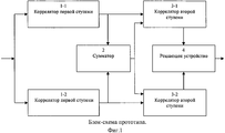
Блок-схема прототипа приведена на фиг.1; пояснения по ней приведены ниже при описании принципа действия прототипа.The block diagram of the prototype is shown in figure 1; explanations on it are given below when describing the principle of operation of the prototype.
Принцип действия прототипа состоит в следующем. Для каждого возможного момента прихода связного сигнала вычисляется взаимная корреляция между принятым сигналом и каждым из двух возможных символов S0(n) или S1(n). Это действие выполняется корреляторами первой ступени (соответственно позиции 1-1 и 1-2 на фиг.1). В данном случае корреляторы первой ступени по существу являются согласованными фильтрами, т.е. каждый коррелятор первой ступени играет роль согласованного с соответствующим символом фильтра. В результате выполнения этой функции на выходах корреляторов первой ступени 1-1 и 1-2 формируются временные реализации, причем на выходе того коррелятора, опорное колебание которого совпадает с фактически переданным символом, эта временная реализация есть оценка ИХК в рабочей полосе частот (с шумом), а на выходе другого коррелятора - только шум. В связи с тем что прототипу информация о том, какой именно из двух возможных символов был передан, неизвестна, в нем осуществляется суммирование (одноименных временных отсчетов) временных реализаций, сформированных на выходах обоих корреляторов первой ступени (сумматор 2 на фиг.1). Этот результат суммирования оценку ИХК заведомо содержит. Сумматор 2 является также накапливающим на скользящем интервале времени, т.е. в нем накапливаются массивы оценок ИХК (в смеси с шумами), формируемые последовательно во времени по мере прихода серии связных символов. Подобное накопление необходимо в, частности, в обеспечении снижения корреляции шумов на входах каждого из корреляторов второй ступени. Количество указанных накапливаемых реализаций ограничено как количеством содержащихся в передаваемом сообщении символов, так и (это более жесткое условие) интервалом стабильности ИХК.The principle of operation of the prototype is as follows. For each possible moment of arrival of the connected signal, a cross-correlation between the received signal and each of the two possible symbols S0 (n) or S1 (n) is calculated. This action is performed by the correlators of the first stage (respectively, positions 1-1 and 1-2 in figure 1). In this case, the correlators of the first stage are essentially matched filters, i.e. each correlator of the first stage plays the role of a filter consistent with the corresponding symbol. As a result of performing this function, temporary implementations are formed at the outputs of the correlators of the first stage 1-1 and 1-2, and at the output of that correlator whose reference oscillation coincides with the actually transmitted symbol, this temporary implementation is an estimate of the ICR in the working frequency band (with noise) , and at the output of another correlator - only noise. Due to the fact that the prototype information about which of the two possible symbols was transmitted is unknown, it sums up (the same time samples) time realizations generated at the outputs of both correlators of the first stage (
Далее реализуется вычисление корреляции между оценкой ИРК (она формируется на выходе сумматора 2 и подается на опорные входы корреляторов второй ступени) и каждой из временных реализаций, сформированных на выходах корреляторов первой ступени 1-1 и 1-2. Эта функция выполняется в корреляторах второй ступени (позиции 3-1 и 3-2 на фиг.1).Next, the calculation of the correlation between the estimate of the KFM (it is formed at the output of the
Далее для конкретности, положим, что передан символ S0(n). При этом в корреляторе второй ступени 3-1 фактически формируется отклик, пропорциональный энергии переданного многолучевого сигнала (т.е. искаженного по форме символа S0(n)), что соответствует эффекту когерентного сложения лучей. Этот отклик характеризуется высоким уровнем. На выходе же коррелятора второй ступени 3-2 в данной ситуации формируется лишь реализация шума. У нее низкий уровень главным образом потому, что поступающие на входы коррелятора второй ступени 3-2 шумы при большом количестве накапливаемых в сумматоре 2 реализаций оценки ИХК практически не коррелированы. Далее при сравнении (в решающем устройстве 4) между собой и/или с порогом уровней откликов, сформированных на выходах корреляторов второй ступени 3-1 и 3-2, принимается решение о фактически переданном символе. Так, в рассматриваемом случае большим и/или превышающим порог будет, как правило, уровень на выходе коррелятора второй ступени 2-1, что приведет (так же, как правило, т.е. как тенденция) к принятию решения о том, что предан символ S0(n), что в рассматриваемой ситуации и является правильным решением.Further, for concreteness, we assume that the symbol S0 (n) is transmitted. Moreover, in the correlator of the second stage 3-1, a response is actually formed proportional to the energy of the transmitted multipath signal (i.e., the symbol S0 (n) distorted in the shape of the symbol), which corresponds to the effect of coherent addition of rays. This response is characterized by a high level. At the output of the correlator of the second stage 3-2 in this situation, only the realization of noise is formed. It has a low level, mainly because the noise coming to the inputs of the correlator of the second stage with 3-2 noises is practically not correlated with a large number of implementations accumulated in the
Таким образом, в прототипе проблема временного рассеяния энергии сигнала связи решена, поскольку, как отмечено выше, достигнут эффект, эквивалентный когерентному сложению всех лучей (точнее, сигналов, пришедших по всем лучам).Thus, in the prototype, the problem of temporal dispersion of the energy of the communication signal is solved, because, as noted above, an effect is achieved that is equivalent to the coherent addition of all the rays (more precisely, the signals that came along all the rays).
Недостатком прототипа является низкое качество декодирования, имеющее место при приеме сообщения, состоящего из малого количества символов, или при сравнительно малом интервале стабильности ИХК. Так, при приеме сообщения, состоящего из одиночного символа, в сумматоре 2 прототипа формируется результат суммирования откликов корреляторов первой ступени 1-1 и 1-2 на принимаемую аддитивную смесь информационного импульса и шума. В этом случае на обоих входах каждого из корреляторов второй ступени шумы в значительной степени коррелированны. Эта коррелированность шумов существенно нивелирует различия в откликах корреляторов второй ступени 2-1 и 2-2 на принимаемый сигнал и тем самым снижает тенденцию к принятию правильного решения. По мере увеличения количества символов в сообщении действие указанного выше фактора, снижающего качество декодирования, хоть и уменьшается, но весьма плавно. Малый интервал стабильности ИХК в свете приведенного пояснения причины низкого качества декодирования в прототипе приводит к тем же последствиям, что и малое количество символов в сообщении.The disadvantage of the prototype is the low quality of decoding that occurs when receiving a message consisting of a small number of characters, or with a relatively small interval of stability of the ICC. So, when receiving a message consisting of a single character, in the
Целью заявляемого устройства является устранение указанного недостатка прототипа, т.е. обеспечение возможности приема (декодирования) сообщения вне зависимости от указанных факторов. Цель достигается тем, что в устройство для декодирования сигналов, содержащее два коррелятора первой ступени и два коррелятора второй ступени, а также решающее устройство, причем общий вход корреляторов первой ступени является входом устройства декодирования, выходы первого и второго корреляторов первой ступени подключены к первым входам соответственно первого и второго корреляторов второй ступени, выходы корреляторов второй ступени подключены к входам решающего устройства, а выход решающего устройства является выходом устройства декодирования, введены два дополнительных коррелятора второй ступени, а также два блока задержки, причем выход первого коррелятора первой ступени дополнительно подключен к первому входу первого дополнительного коррелятора второй ступени и к входу первого блока задержки, выход которого подключен ко вторым входам первого и второго корреляторов второй ступени, выход второго коррелятора первой ступени дополнительно подключен к первому входу второго дополнительного коррелятора второй ступени и к входу второго блока задержки, выход которого подключен ко вторым входам первого и второго дополнительных корреляторов второй ступени, а выходы дополнительных корреляторов второй ступени подключены к входам решающего устройства.The purpose of the claimed device is to eliminate the specified disadvantage of the prototype, i.e. providing the ability to receive (decode) the message regardless of these factors. The goal is achieved in that in a device for decoding signals containing two correlators of the first stage and two correlators of the second stage, as well as a solver, the common input of the correlators of the first stage being the input of the decoding device, the outputs of the first and second correlators of the first stage are connected to the first inputs, respectively the first and second correlators of the second stage, the outputs of the correlators of the second stage are connected to the inputs of the solving device, and the output of the solving device is the output of the device For coding, two additional correlators of the second stage are introduced, as well as two delay units, the output of the first correlator of the first stage being additionally connected to the first input of the first additional correlator of the second stage and to the input of the first delay unit, the output of which is connected to the second inputs of the first and second correlators of the second stage , the output of the second correlator of the first stage is additionally connected to the first input of the second additional correlator of the second stage and to the input of the second delay unit, the output of which connected to the second inputs of the first and second additional correlators of the second stage, and the outputs of the additional correlators of the second stage are connected to the inputs of the solver.
Перечисленная совокупность признаков заявляемого устройства декодирования (являющаяся минимально необходимой) соответствует его варианту, рассчитанному на прием двухпозиционного кода (т.е. кода, принимающего одно из двух значений, например «0» или «1»). В общем случае при приеме N-позиционного кода декодер содержит по N корреляторов первой ступени и блоков задержки, а также N2 корреляторов второй ступени.The listed set of features of the inventive decoding device (which is the minimum necessary) corresponds to its version, designed to receive a two-position code (ie, a code that takes one of two values, for example, "0" or "1"). In the general case, when receiving an N-position code, the decoder contains N correlators of the first stage and delay blocks, as well as N 2 correlators of the second stage.
Блок-схема заявляемого объекта приведена на фиг.2, где обозначены:The block diagram of the claimed object is shown in figure 2, where indicated:
- 5-1 и 5-2 - корреляторы первой ступени;- 5-1 and 5-2 - correlators of the first stage;
- 6-1 и 6-2 - блоки задержки;- 6-1 and 6-2 - delay blocks;
- 7-1 и 7-3 - корреляторы второй ступени;- 7-1 and 7-3 - correlators of the second stage;
- 7-2 и 7-4 - дополнительные корреляторы второй ступени;- 7-2 and 7-4 - additional correlators of the second stage;
- 8 - решающее устройство.- 8 - decisive device.
Каждый коррелятор первой ступени (5-1, 5-2) реализуется, например, в соответствии с блок-схемой на рис.5.14, с.295 книги [6]. При этом сигнальным входом коррелятора является нижний на указанном рис.5.14 вход, на который подается принимаемый сигнал x(n). Опорная же функция коррелятора первой ступени (на указанном рис.5.14 она обозначена как h(n)) хранится в его долговременной памяти, на рис.5.14 для простоты не показанной. В заявляемом устройстве опорные функции корреляторов первой ступени h(n) имеют вид:Each correlator of the first stage (5-1, 5-2) is implemented, for example, in accordance with the block diagram in Fig.5.14, p.295 of the book [6]. In this case, the signal input of the correlator is the lower input in the indicated Fig. 5.14, to which the received signal x (n) is supplied. The reference function of the correlator of the first stage (in the indicated Fig. 5.14 it is designated as h (n)) is stored in its long-term memory, which is not shown in Fig. 5.14 for simplicity. In the claimed device, the support functions of the correlators of the first stage h (n) are:
- коррелятор 5-1 - h1(n)=S0(n);- correlator 5-1 - h1 (n) = S0 (n);
- коррелятор 5-2 - h2(n)=S1(n).- correlator 5-2 - h2 (n) = S1 (n).
При реализации коррелятора первой ступени в спектральной области (т.е. на базе процедуры быстрой свертки) над опорной функцией каждого из этих корреляторов заранее выполняется операция дискретного преобразования Фурье (ДПФ), и массив результата ДПФ (результат его комплексного сопряжения) запоминается в долговременной памяти соответствующего коррелятора первой ступени. Над массивами отсчетов входного сигнала x(n) также выполняется ДПФ, далее выполняется поэлементное перемножение (т.е. перемножение одноименных отсчетов) массивов результатов ДПФ над опорной функцией и входным сигналом и обратное ДПФ (ОДПФ) от массива результатов указанного перемножения. Период обновления массива отсчетов входного сигнала при смежных по времени циклах вычисления корреляции в каждом из корреляторов первой ступени обычно выбирается равным длительности каждого из импульсов (сигналов) S0(n), S1(n) (длительности всех этих импульсов в простейшем случае совпадают), при этом длина окна ДПФ равна двойной длительности каждого из этих сигналов. Два независимо работающих коррелятора первой ступени показаны на фиг.2 условно. При их реализации в спектральной области водящая в состав этих корреляторов процедура ДПФ от входного сигнала может быть для всех них общей.When the correlator of the first stage is implemented in the spectral region (i.e., based on the fast convolution procedure), the discrete Fourier transform (DFT) operation is performed in advance on the support function of each of these correlators, and the array of the DFT result (the result of its complex conjugation) is stored in long-term memory corresponding correlator of the first stage. DFT is also performed on the arrays of samples of the input signal x (n), then elementwise multiplication (i.e., multiplication of the same samples) of the arrays of DFT results over the reference function and input signal and the inverse DFT (DFT) from the array of the results of the specified multiplication are performed. The period of updating the array of samples of the input signal for adjacent time cycles of calculating the correlation in each of the correlators of the first stage is usually chosen equal to the duration of each of the pulses (signals) S0 (n), S1 (n) (the durations of all these pulses coincide in the simplest case), when the length of the DFT window is equal to the double duration of each of these signals. Two independently working correlators of the first stage are shown in FIG. 2 conditionally. When implemented in the spectral region, the DFT procedure leading to the composition of these correlators from the input signal may be common to all of them.
Возможен также эквивалентный рассмотренному вариант блок-схемы коррелятора первой ступени во временной области; описание этого варианта коррелятора приведено в [6], рис.6.186, с.418, где (в соответствии с сегодняшними возможностями техники) вместо рециркулирующей линии задержки, хранящей массив временных отсчетов опорного сигнала при его жестком ограничении, реализуется многоразрядный регистр сдвига, хранящий те же отсчеты, представленные многоразрядными кодовыми словами.A variant of the block diagram of the correlator of the first stage in the time domain equivalent to the one considered is also possible; A description of this correlator option is given in [6], Fig. 6.186, p.418, where (in accordance with the current capabilities of the technique) instead of a recirculating delay line that stores an array of time samples of the reference signal when it is strictly limited, a multi-bit shift register is stored that stores the samples represented by multi-bit code words.
Динамика обновления входных и выходных данных рассматриваемого коррелятора иллюстрируется, например, в [7, с.76-78].The dynamics of updating the input and output data of the correlator under consideration is illustrated, for example, in [7, pp. 76-78].
Каждый из блоков 6-1 и 6-2 осуществляет задержку поступающего на его вход сигнала на время, равное периоду следования сигналов в передаваемой последовательности Т (этот период, как правило, равен длительности каждого их этих сигналов), и реализуется, например, как многоразрядный регистр сдвига.Each of blocks 6-1 and 6-2 delays the signal arriving at its input for a time equal to the period of the signals in the transmitted sequence T (this period, as a rule, is equal to the duration of each of these signals), and is implemented, for example, as a multi-bit shift register.
Каждый (в том числе и дополнительный) коррелятор второй ступени 7-1…7-4 реализуется аналогично коррелятору первой ступени (предпочтительно в варианте во временной области), с той лишь разницей, что нем отсутствует долговременная память, хранящая опорное колебание. Длительность цикла обновления сигнала на выходе каждого коррелятора второй ступени может составлять, например, один период дискретизации входных сигналов.Each (including additional) correlator of the second stage 7-1 ... 7-4 is implemented similarly to the correlator of the first stage (preferably in the time-domain variant), with the only difference being that it does not have a long-term memory that stores the reference oscillation. The duration of the signal update cycle at the output of each correlator of the second stage can be, for example, one sampling period of the input signals.
Решающее устройство 8 представляет собой схему сравнения текущих уровней сигналов на его входах между собой и/или с заданным порогом, хранящимся в его долговременной памяти: В случае превышения максимального из уровней четырех входных (для устройства 8) сигналов порога на выходе решающего устройства 8 формируется код комбинации их двух принятых и декодированных сигналов. Так, например, при передаче позиций кода «0» и «1» соответственно сигналами S0(n) и S1(n) в том случае, если максимальным и превысившим порог будет сигнал на выходе коррелятора второй ступени 7-1, 7-2, 7-3 или 7-4 (в заявляемом устройстве все эти корреляторы по выполняемой функции и их реализации совпадают), решающее устройство 8 в качестве решения формирует кодовую последовательность соответственно «0-0» (т.е. первый из принятых сигналов декодирован как «0» и второй - тоже как «0»), «0-1», «1-0» или «1-1».The solving device 8 is a comparison chart of the current signal levels at its inputs with each other and / or with a predetermined threshold stored in its long-term memory: In case of exceeding the maximum of the four input signals (for device 8) of the threshold, the code is generated at the output of the solving device 8 combinations of their two received and decoded signals. So, for example, when transmitting code positions “0” and “1”, respectively, with signals S0 (n) and S1 (n), if the signal at the output of the correlator of the second stage 7-1, 7-2 is maximum and exceeds the threshold, 7-3 or 7-4 (in the inventive device, all these correlators for the function performed and their implementation coincide), the solving device 8 as a solution generates a code sequence, respectively, “0-0” (ie, the first of the received signals is decoded as “ 0 "and the second - also as" 0 ")," 0-1 "," 1-0 "or" 1-1 ".
Принцип действия заявляемого устройства состоит в следующем. При передаче последовательности импульсов, например, S1(n)-S0(n) (т.е. кодовой комбинации «1-0») в момент прихода первого сигнала этой последовательности (точнее, в момент прихода его заднего фронта) на выходе коррелятора первой ступени 5-2 (опорное колебание которого совпадает с информационным импульсом S1(n)) формируется отклик, равный свертке ИХК с автокорреляционной функцией (АКФ) импульса S1(n) в смеси с шумом. Считаем далее этот момент условно нулевым. В этот же момент на выходе коррелятора первой ступени 5-1 (опорное колебание которого совпадает с информационным импульсом S0(n)) формируется отклик, содержащий только шум. Далее в момент Т прихода второго сигнала этой последовательности на выходе коррелятора первой ступени 5-1 (опорное колебание которого совпадает с информационным импульсом S0(n)) формируется отклик, равный свертке ИХК с АКФ импульса S0(n) в смеси с шумом. (Считаем, что АКФ обоих сигналов совпадают.) В этот же момент на выходе коррелятора первой ступени 5-2 (опорное колебание которого совпадает с информационным импульсом S1(n)), формируется отклик, содержащий только реализацию шума. Тогда в момент Т на входах (дополнительного) коррелятора второй ступени 7-3 формируются две совпадающие по форме свертки ИХК с АКФ передаваемых импульсов (сигналов) S0(n) и S1(n), каждая в смеси с шумами; в итоге сигнал на выходе этого коррелятора второй ступени 7-3 имеет сравнительно высокий уровень. В этот же момент времени на одном из входов коррелятора второй ступени 7-4 формируется свертка ИХК с АКФ импульса S0(n) в смеси с шумом, а на втором его входе - только реализация шума; одновременно с этим на всех входах корреляторов второй ступени 7-1 и 7-2 формируются только реализации шума. Реализации шума на всех входах всех корреляторов второй ступени некоррелированы. Таким образом, имеется статистическая тенденция к тому, что при приеме переданной комбинации сигналов S1(n)-S0(n) (т.е. кодовой последовательности «1-0») уровень сигнала на выходе коррелятора второй ступени 7-3 будет существенно превышать таковой на выходе коррелятора второй ступени 7-4 и в еще большей степени - на выходах корреляторов второй ступени 7-1 и 7-2. При этом решающее устройство 8 формирует решение, соответствующее переданной кодовой комбинации.The principle of operation of the claimed device is as follows. When transmitting a sequence of pulses, for example, S1 (n) -S0 (n) (ie, the code combination “1-0”) at the moment of the arrival of the first signal of this sequence (more precisely, at the moment of arrival of its trailing edge) at the output of the correlator of the first steps 5-2 (the reference oscillation of which coincides with the information pulse S1 (n)), a response is formed equal to the convolution of the ICC with the autocorrelation function (ACF) of the pulse S1 (n) in a mixture with noise. We further consider this moment to be conditionally zero. At the same moment, at the output of the correlator of the first stage 5-1 (whose reference oscillation coincides with the information pulse S0 (n)), a response is formed containing only noise. Then, at the moment T of the arrival of the second signal of this sequence, the output of the correlator of the first stage 5-1 (the reference oscillation of which coincides with the information pulse S0 (n)) generates a response equal to the convolution of the ICR with the ACF of the pulse S0 (n) mixed with noise. (We believe that the ACF of both signals coincide.) At the same moment, at the output of the correlator of the first stage 5-2 (whose reference oscillation coincides with the information pulse S1 (n)), a response is formed containing only the implementation of noise. Then, at the moment T, at the inputs of the (additional) correlator of the second stage 7-3, two convolute ICH convolutions with ACF of transmitted pulses (signals) S0 (n) and S1 (n) are formed, each mixed with noise; as a result, the signal at the output of this second stage correlator 7-3 has a relatively high level. At the same time, at one of the inputs of the correlator of the second stage 7-4, a convolution of the ICC with the ACF of the pulse S0 (n) in a mixture with noise is formed, and at its second input, only the implementation of noise; at the same time, only noise implementations are formed at all inputs of the second-stage correlators 7-1 and 7-2. Noise implementations at all inputs of all second-stage correlators are uncorrelated. Thus, there is a statistical tendency for the reception of the transmitted combination of signals S1 (n) -S0 (n) (ie, the code sequence “1-0”) the signal level at the output of the correlator of the second stage 7-3 will significantly exceed such at the output of the correlator of the second stage 7-4 and to an even greater extent - at the outputs of the correlators of the second stage 7-1 and 7-2. In this case, the decision device 8 generates a decision corresponding to the transmitted code combination.
При передаче кодовой комбинации, например, «0-0» совпадающие по форме свертки ИХК с АКФ передаваемых импульсов (сигналов) S0(n) и опять же S0(n) будут одновременно (с учетом задержки, вводимой в данной ситуации блоком задержки 6-1) формироваться только на входах коррелятора второй ступени 7-1, и при этом решающее устройство 8 выработает решение в пользу кодовой комбинации «0-0».When transmitting a code combination, for example, “0-0”, the convolution of the ICC with the ACF of the transmitted pulses (signals) S0 (n) and again S0 (n) will be simultaneously (taking into account the delay introduced in this situation by the delay unit 6- 1) to be formed only at the inputs of the correlator of the second stage 7-1, and at the same time, the decisive device 8 will develop a solution in favor of the code combination “0-0”.
Заявляемое устройство обеспечивает высокое качество декодирования даже при малом (но не меньшем двух) количестве передаваемых в сообщении символов и малом интервале стабильности ИХК (достаточно интервала стабильности ИХК, не меньшего двойной длительности символа, т.е. 2T).The inventive device provides high quality decoding even with a small (but not less than two) number of characters transmitted in the message and a small interval of stability of the ICC (an interval of stability of the ICC is sufficient, not less than double the duration of the character, i.e. 2T).
Таким образом, цель изобретения достигается.Thus, the object of the invention is achieved.
ЛитератураLiterature
1. Д.Д. Кловский. Передача дискретных сообщений по радиоканалам. М.: Связь. 1969.1. D.D. Klovsky. Transmission of discrete messages over the air. M .: Communication. 1969.
2. Устройство приема дискретных сигналов в многолучевом канале связи. Патент РФ №2048701.2. A device for receiving discrete signals in a multipath communication channel. RF patent No. 2048701.
3. Цифровое устройство для демодуляции дискретных сигналов в многолучевом канале связи. Патент РФ №2267230.3. Digital device for demodulating discrete signals in a multipath communication channel. RF patent No. 2267230.
4. Устройство для передачи дискретных сигналов в многолучевом канале связи. Патент РФ №959291.4. Device for transmitting discrete signals in a multipath communication channel. RF patent No. 959291.
5. Sussman S.M. A matched filter communication system for multipath channels // IEEE Trans. IT - 6. N 3. June 1960.5. Sussman S.M. A matched filter communication system for multipath channels // IEEE Trans. IT - 6. N 3. June 1960.
6. «Применение цифровой обработки сигналов», под ред. Э. Оппенгейма. М.: Мир. 1980.6. “The use of digital signal processing”, ed. E. Oppenheim. M .: World. 1980.
7. Л. Рабинер, Б. Гоулд. Теория и применение цифровой обработки сигналов. М.: Мир. 1978.7. L. Rabiner, B. Gould. Theory and application of digital signal processing. M .: World. 1978.
Claims (1)
Priority Applications (1)
| Application Number | Priority Date | Filing Date | Title |
|---|---|---|---|
| RU2013150766/08A RU2541908C1 (en) | 2013-11-14 | 2013-11-14 | Device for decoding signals passing through multibeam communication channel |
Applications Claiming Priority (1)
| Application Number | Priority Date | Filing Date | Title |
|---|---|---|---|
| RU2013150766/08A RU2541908C1 (en) | 2013-11-14 | 2013-11-14 | Device for decoding signals passing through multibeam communication channel |
Publications (1)
| Publication Number | Publication Date |
|---|---|
| RU2541908C1 true RU2541908C1 (en) | 2015-02-20 |
Family
ID=53288823
Family Applications (1)
| Application Number | Title | Priority Date | Filing Date |
|---|---|---|---|
| RU2013150766/08A RU2541908C1 (en) | 2013-11-14 | 2013-11-14 | Device for decoding signals passing through multibeam communication channel |
Country Status (1)
| Country | Link |
|---|---|
| RU (1) | RU2541908C1 (en) |
Citations (5)
| Publication number | Priority date | Publication date | Assignee | Title |
|---|---|---|---|---|
| RU2048701C1 (en) * | 1992-04-15 | 1995-11-20 | Войсковая часть 60130 | Device for receiving of digital signals in multiple-beam channel |
| US6130923A (en) * | 1998-12-11 | 2000-10-10 | Qualcomm Incorporated | Lock detection for multipath wireless receiver |
| RU2163054C2 (en) * | 1998-06-16 | 2001-02-10 | Алышев Юрий Витальевич | Method and device for joint demodulation and decoding of continuous-phase binary modulation signals in convolutional-coding systems using character interleaving-deinterleaving system for multibeam radio channels |
| RU2267230C1 (en) * | 2004-06-23 | 2005-12-27 | Федеральное государственное унитарное предприятие Омский научно-исследовательский институт приборостроения | Digital device for demodulation of discontinuous signals in multi-beam communication channel |
| RU2354048C1 (en) * | 2007-11-28 | 2009-04-27 | Открытое акционерное общество "Концерн "Созвездие" | Method and communication system with fast acquisition by ultra-wideband signals |
-
2013
- 2013-11-14 RU RU2013150766/08A patent/RU2541908C1/en not_active IP Right Cessation
Patent Citations (5)
| Publication number | Priority date | Publication date | Assignee | Title |
|---|---|---|---|---|
| RU2048701C1 (en) * | 1992-04-15 | 1995-11-20 | Войсковая часть 60130 | Device for receiving of digital signals in multiple-beam channel |
| RU2163054C2 (en) * | 1998-06-16 | 2001-02-10 | Алышев Юрий Витальевич | Method and device for joint demodulation and decoding of continuous-phase binary modulation signals in convolutional-coding systems using character interleaving-deinterleaving system for multibeam radio channels |
| US6130923A (en) * | 1998-12-11 | 2000-10-10 | Qualcomm Incorporated | Lock detection for multipath wireless receiver |
| RU2267230C1 (en) * | 2004-06-23 | 2005-12-27 | Федеральное государственное унитарное предприятие Омский научно-исследовательский институт приборостроения | Digital device for demodulation of discontinuous signals in multi-beam communication channel |
| RU2354048C1 (en) * | 2007-11-28 | 2009-04-27 | Открытое акционерное общество "Концерн "Созвездие" | Method and communication system with fast acquisition by ultra-wideband signals |
Similar Documents
| Publication | Publication Date | Title |
|---|---|---|
| Uwaechia et al. | A review on sparse channel estimation in ofdm system using compressed sensing | |
| JP3959064B2 (en) | Method and apparatus for searching for known sequences | |
| CN101626354B (en) | Noise estimation method and noise estimation device of multipath channel | |
| RU141688U1 (en) | TACT SYNCHRONIZATION DEVICE FOR INFORMATION COMPOSITION SERIAL SIGNAL | |
| US9014317B2 (en) | Method, apparatus, and system for frequency offset estimation and channel estimation | |
| RU2541908C1 (en) | Device for decoding signals passing through multibeam communication channel | |
| CN110191079B (en) | Non-coherent combined capturing method and device | |
| RU2544178C1 (en) | Device for receiving discrete signals transmitted through multibeam communication channel | |
| RU2528134C1 (en) | Device for decoding signals passing through multibeam communication channel | |
| US9787517B2 (en) | Coarse timing | |
| US8948333B2 (en) | Clock frequency error detecting device | |
| US10257004B2 (en) | Inter-block interference suppression using a null guard interval | |
| US10680666B2 (en) | Timing estimation device and timing estimation method | |
| RU2658335C1 (en) | Method of joint evaluation of communication channel and soft demodulation for cofdm signals and device for its implementation | |
| RU2565014C2 (en) | Method of decoding communication signals | |
| KR20160027698A (en) | 2-STEP FDOA/FDOA estimation Method and Apparatus | |
| RU2560102C2 (en) | Device for decoding discrete signals propagating in multibeam channel | |
| JPWO2016051467A1 (en) | Wireless communication apparatus and wireless communication system | |
| RU2310978C2 (en) | Discontinuous matched filter | |
| RU2659478C1 (en) | Digital information reception method with the presence of intersymbol interference | |
| Ito et al. | Estimation of multi-path channels by using the annihilating filter method | |
| KR101300037B1 (en) | An improved UWB receive method employing generalized Gaussian-Laplacian distribution model at UWB-MUI system | |
| RU2549888C1 (en) | Device for decoding discrete signals propagating in multibeam channel | |
| RU172181U1 (en) | DEVICE FOR JOINT TRANSMISSION OF INFORMATION AND TEST SIGNALS WITH FREQUENCY SHIFT IN CHANNELS WITH INTER-CHARACTER INTERFERENCE | |
| RU2541199C1 (en) | Device for decoding discrete signals propagating in multibeam channel |
Legal Events
| Date | Code | Title | Description |
|---|---|---|---|
| MM4A | The patent is invalid due to non-payment of fees |
Effective date: 20161115 |